

Introduction
Vision has been a strongly useful sense to locate a prey and a predator since the Cambrian explosion (e.g. Parker, Reference Parker2003), and reduction of visibility should be, therefore, an important property of the body surface. An array of minute protuberances of about 100 nm high or less has been found on the surface of some invertebrates across various taxa. It is often referred as a ‘nipple array’ because of the shape of protuberances or ‘moth-eye structure’ because of its original description on the compound eyes of a night moth (Bernhard, Reference Bernhard1967). This structure forms a gradient of refractivity, resulting in a reduction of light reflectance and an increase of transmittance (Bernhard, Reference Bernhard1967; Wilson & Hutley, Reference Wilson and Hutley1982). Moreover, the nipple array on cicada wing serves bactericidal purposes (Ivanova et al., Reference Ivanova, Hasan, Webb, Truong, Watson, Watson, Baulin, Pogodin, Wang, Tobin, Löbbe and Crawford2012, Reference Ivanova, Hasan, Webb, Gervinskas, Juodkazis, Truong, Wu, Lamb, Baulin, Watson, Watson, Mainwaring and Crawford2013). In contrast to terrestrial environments, less attention has been paid to the biological functions of the nipple array in aquatic environments, although the presence of a nipple array was also reported from some marine invertebrates, such as entoprocts, copepods and tunicates (Hirose et al., Reference Hirose, Saito, Hashimoto and Watanabe1990; Iseto & Hirose, Reference Iseto and Hirose2010; Hirose & Uyeno, Reference Hirose and Uyeno2014). The functions underwater have been poorly investigated, probably because of the difficulties in measuring physical properties of wet, soft materials.
Tunicates are marine invertebrate chordates with cellulosic outer covering synthesized by their epidermis, an integumentary matrix (tunic) in ascidians and thaliaceans (i.e. salps, doliolids and pyrosomes) and filtration apparatus (house) in appendicularians (Belton et al., Reference Belton, Tanner, Cartier and Chanzy1989; Van Daele et al., Reference Van Daele, Revol, Gaill and Goffinet1992; Hirose et al., Reference Hirose, Kimura, Itoh and Nishikawa1999; Kimura et al., Reference Kimura, Ohshima, Hirose, Nishikawa and Itoh2001). The tunics are expected to have unique properties among the metazoan integuments because the biosynthesis of cellulose has never been reported in any other metazoan taxa, and cellulose synthase genes have been exclusively found in all tunicate genomes (Inoue et al., Reference Inoue, Nakashima and Satoh2019). The outermost surface of the tunic is covered with a cuticle that has a dense structure probably to prevent the invasion of microbes into the tunic matrix. In some ascidian and thaliacean species, the cuticular surface has a nipple array that is comprised of minute protrusions ~20–130 nm in height (Hirose et al., Reference Hirose, Saito, Hashimoto and Watanabe1990, Reference Hirose, Nishikawa, Saito and Watanabe1992, Reference Hirose, Lambert, Kusakabe and Nishikawa1997, Reference Hirose, Kimura, Itoh and Nishikawa1999). In salps, a pelagic tunicate, the nipple array on the tunic surface is found only in species distributed in the epipelagic layer during the daytime. This suggests that the amount of ambient light is related to functions, such as visibility, of this structure. While light reflection on the tunic is naturally small even on the flat surface because of the small difference in refractive indices between the tunic and seawater, simulations based on the surface structure indicate that the nipple array further reduces light reflection to some extent (Hirose et al., Reference Hirose, Sakai, Shibata, Nishii, Mayama, Miyauchi and Nishikawa2015; Kakiuchida et al., Reference Kakiuchida, Sakai, Nishikawa and Hirose2017; Sakai et al., Reference Sakai, Kakiuchida, Nishikawa and Hirose2018). The ascidian tunic has more protective functions than the thaliacean tunic because sessile ascidians cannot escape from hostile environments and natural enemies by migration.
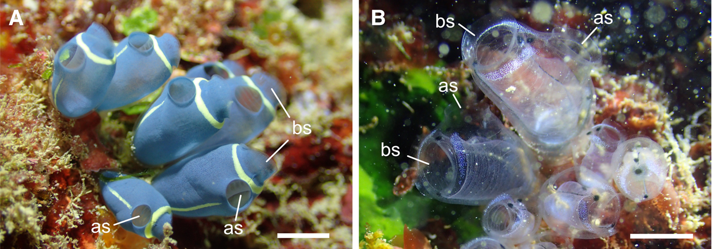
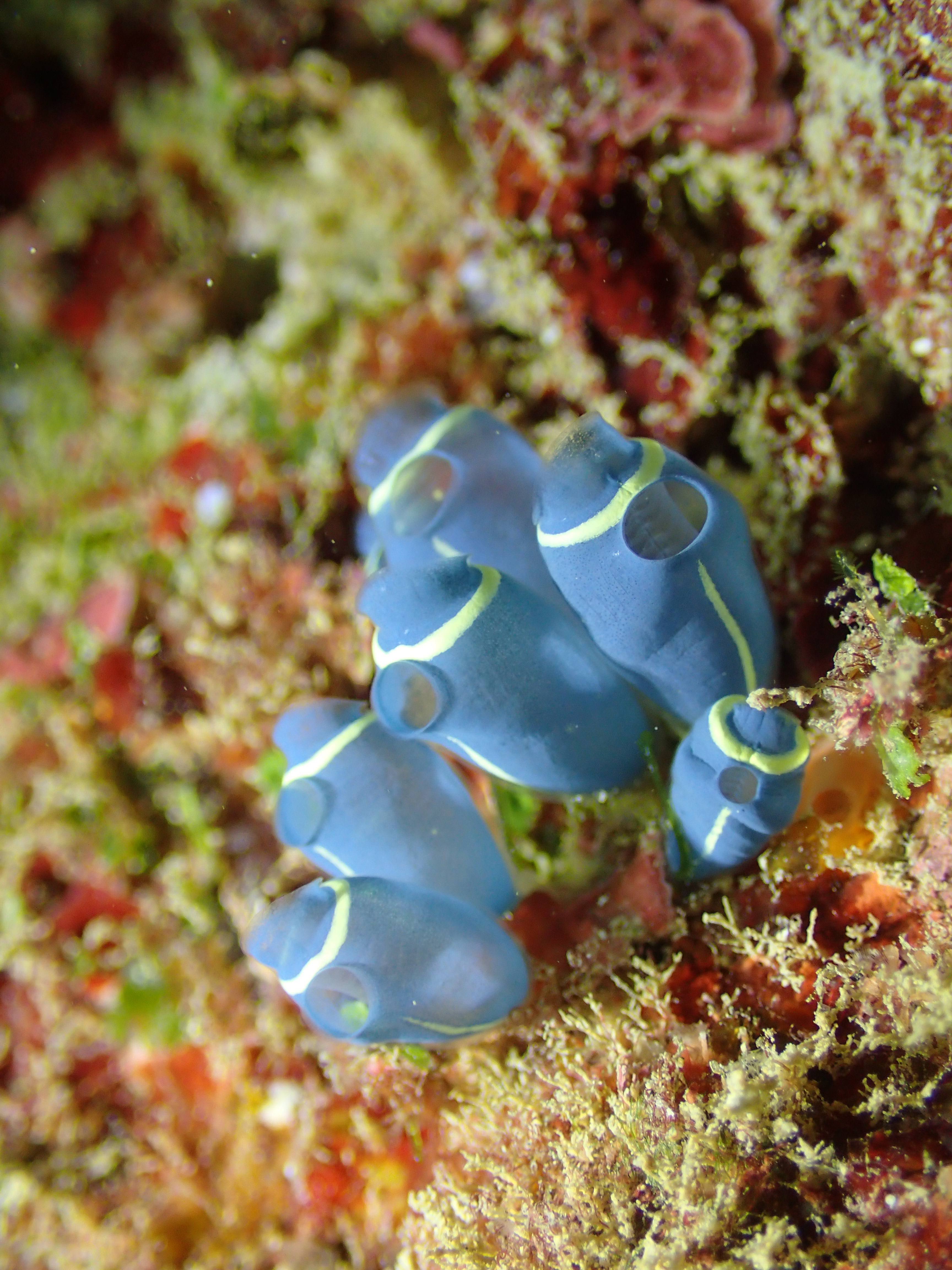
Clavelina cyclus Tokioka & Nishikawa, 1975 and C. obesa Nishikawa & Tokioka 1976 are colonial ascidians commonly found on reef slopes of the Okinawan coral reefs. Whereas the tunic of the latter is transparent, the former has a blue aspect due to the colouration of the mantle (Figure 1). When we peeled the tunic from mantle, the tunic was transparent and the mantle was still bluish. In this study, we examined the fine surface structures, hardness, wettability and refractive indices of the tunics of the two species to understand the physical properties of the ascidian tunic. The tunic surface had a nipple array in both species, and the tunic cuticle of C. cyclus repeatedly got bent into folds forming parallel plications on the tunic surface. Based on the surface structures and refractive indices of these tunics, light reflectance on the tunic surface was calculated using rigorous coupled wave analysis (RCWA). Furthermore, we fabricated nano-imprinted plates imitating the parallel plications on the tunic surface to evaluate the functional importance of this structure.

Fig. 1. The colonies of Clavelina cyclus (A) and C. obesa (B). These in situ photographs are taken at the sampling site by Mr Shu Chihara. as, atrial siphon; bs, branchial siphon. Scale bars indicate ~1 cm.
Materials and methods
Animals
Colonies of C. cyclus and C. obesa were collected by scuba divers at a 4–5 m depth on the reef slopes at Sunabe (Chatan, Okinawajima Island, Japan: 26°19′54″N 127°44′27″E) on 16 November 2017 and 19 March 2018. The animals were placed in a 500-ml plastic jar filled with seawater and brought to the laboratory at the University of the Ryukyus (Okinawa Prefecture). Some specimens were reared in artificial seawater (Marine Art SF-1: Osakayakken, Japan) for a few days while being transported to the laboratory at the National Institute of Advanced Industrial Science and Technology (AIST, Aichi Prefecture).
Microscopy
The colonies were fixed in 2.5% glutaraldehyde, 0.45 M sucrose and 0.1 M cacodylate (pH 7.5) and stored at 4°C. Pieces of the tunic were cut from the fixed colonies using a razor blade, briefly rinsed with 0.45 M sucrose and 0.1 M cacodylate buffer, and post-fixed with 1% osmium tetroxide in a 0.1 M cacodylate buffer at 4°C for 1.5 h. Specimens were dehydrated via an ethanol series, cleared with n-butyl glycidyl ether and embedded in Agar Low Viscosity Resin (Agar Scientific). Thin sections were stained with uranyl acetate and lead citrate, and examined in a transmission electron microscope (JEM1011, JEOL) at 80 kV. The heights and intervals of the cuticular protrusions and plications were measured using electron micrographs.
Fabrication of nano-imprinted plates
The parallel plications were replicated onto a transparent polymer according to the following procedures. The surface relief structure was fabricated on a photosensitive azobenzene polymer film. A side-chain type azobenzene polymer (poly-orange tom-1, Tri Chemical Laboratories) was dissolved in cyclohexanone at 10% w/v, and spin-coated on a commercially available glass substrate (S-1111, Matsunami). Holographic surface relief grating was directly formed on the polymer film by photo-isomerization using two-beam interference exposure. The light source was a circularly polarized Ar+ laser (Stabilight 2017, Spectra-Physics) with a wavelength of 514.5 nm. The period of the interference fringe was adjusted to 550 nm. Then, a negative replica of the grating structure was fabricated to transparent thermoset silicone rubber (ELASTOSIL RT601 A/B, Wacker Asahikasei Silicone); RT601-A and -B were mixed at a 9:1 ratio. After deformation, the mixed silicone was placed, in drops, on the holographic-grating-inscribed polymer film and enclosed with walls. The silicone rubber was thermally cured on the hot plate at 85°C for 10 min. The parallel plications were formed on an ultraviolet (UV) curable polymer by the UV nano-imprint process using the released silicone rubber as a transparent mould. A drop of the liquid photopolymer (NOA61, Norland Products) was put on a glass substrate. The liquid was then covered with the silicone rubber mould, pressed manually, and exposed to a high-pressure mercury lamp (HLR100T-2, SEN LIGHTS) for 10 min. After demoulding, the surface structure on the UV-imprinted plate was observed using an atomic force microscope (AFM) (Nanocute, SII Nanotechnology). The refractive index of the UV-curable polymer is 1.56 according to the manufacturer's description.
Hardness of tunics
Each of the C. cyclus zooids was weighted (total wet weight), and the tunic piece, about 7 × 15 mm, was cut from the middle part of the body. The thickness of the tunic was measured using a Vernier calliper. To quantify the hardness of the tunic, we recorded the maximum force necessary to pierce the tunic sheet with a steel rod (1 mm diameter; flat tip) using a digital force gauge DST-2N (IMADA) equipped with a pin attachment (TP-20, IMADA). The measurement was carried out randomly at three separate points selected within each sample, and the median was regarded as the hardness.
Wettability of tunics and nano-imprinted plates
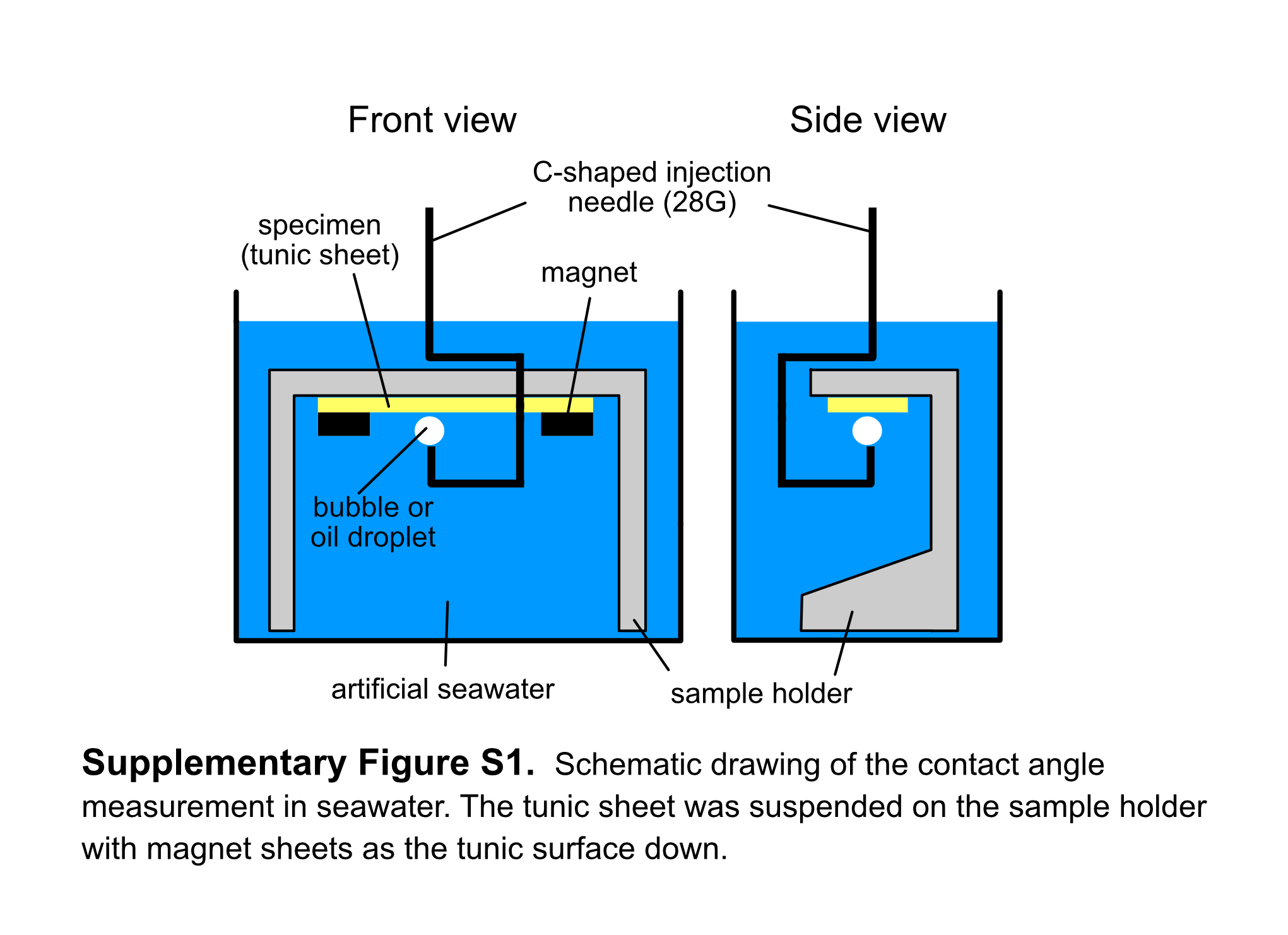
The wettability of the tunic surface was determined on the contact angle of air bubbles and mineral oil (Sigma-Aldrich) in artificial seawater with a contact angle meter LSE-ME2 (NiCK, Japan) using a three-phase system kit (Kyowa Interface Science). Tunic sheets, about 5 × 15 mm, cut from two C. cyclus zooids were suspended on the sample holder, the tunic surface down (Supplementary Figure 1). The images of air bubbles or oil droplets on the specimens were analysed using a software i2win mini (NiCK) to measure the contact angle. We could not measure the contact angles for C. obesa in which large enough tunic specimens were not available. Owing to the fact that we could not control the size of bubbles and oil droplets in the experiment, the size of the bubbles and oil droplets ranged from 0.07 to 8.9 µl and 0.01 to 3.2 µl, respectively. We also measured the contact angles of water droplets (~0.5 µl) in the air and air bubbles in seawater on the nano-imprinted plates with and without the plications, which acted as relief structures. On the plates with the plications, we measured the contact angles of the two directions; the spreading direction of the water drop was either parallel or perpendicular to the plications. Measurements were carried out at 10 distinct points on each of the two samples, and thus, 20 values were obtained for the plates with and without the plications, respectively. Moreover, the analyses of wettability were carried out on plates hydrophilized by ion bombardment using an ion-coater IB-3 (EIKO) and then coated with a water/oil repellent FluoroSurf® FG-5093TH (Fluoro Technology).
Ellipsometry
We examined two samples of C. cyclus and C. obesa tunics; fresh samples were measured and frozen at −20°C, and the same samples were remeasured after thawing at about 25°C to evaluate the effect of freezing and thawing treatments. A sheet of the tunic cut from the Clavelina spp. was spread on a glass plate. The wavelength dispersion of the refractive index was determined in wavelengths between 380 to 1700 nm, using a spectroscopic ellipsometer (M2000, J. A. Woolam) installed with focusing probes. The measurements were carried out at different angles of incidence between 50° and 75°, depending on the surface flatness of the samples. A diffusive light absorbing foil (specular reflectance less than 0.2%; Metal Velvet™, Acktar) was used as the plate to reduce stray light from rear reflection through the transparent samples. The ellipsometric parameters Ψ and Δ were measured as a function of wavelength, and we obtained the coefficient values (a, b, c) and fitting errors (Δa, Δb, Δc). In the calculation of these values, our ellipsometric model incorporated an effective medium approximation (EMA) layer to express the rough surfaces of the tunics. The wavelength dispersion of the refractive index (n) and the range of uncertainty (± Δn) were determined based on the assumption that they adhered to the three-term Cauchy's equation.
 $$n \pm \Delta n = a + b/{\rm \lambda} ^2 + c/{\rm \lambda} ^4 \pm (\Delta a + \Delta b/{\rm \lambda} ^2 + \Delta c/{\rm \lambda} ^4),$$
where the fitting errors expressed 90% confidence limits estimated through fitting calculations in M2000. The refractive index of seawater (35‰ at 25°C) was estimated using the equation given in Quan & Fry (Reference Quan and Fry1995).
Light transmission and reflection on nano-imprinted plates
Light transmittance and reflectance were measured for two plates with relief structures (plications) and without (flat) at wavelengths between 200 and 2500 nm using a spectrophotometer (U4100, Hitachi High-Technologies). The incident angle for transmittance was 0° and the angle for reflectance was 8°. Considering potential light diffraction from the periodic structures on the nano-imprinted surfaces, the hemispherical transmittance and reflectance were measured by an integrating sphere installed in the spectrophotometer. Additionally, the specular reflectance of 590-nm light was measured at variable angles: 20–65° at 5° intervals.
Simulation of light reflectance
We calculated the reflectance of the D-line (589 nm) on the 3-D models of the flat surface and nipple array (with or without the plications) with rigorous coupled wave analysis (RCWA) using DiffractMOD3.2 software (RSoft Design Group). The refractive-index deviation between the tunic and seawater was assumed to be 0.1 based on estimates of refractive indices by ellipsometry. Polarized lights were used for this simulation, i.e. transverse electric (TE) and transverse magnetic (TM) waves. Reflectance including light diffraction was calculated at every degree from 0° to 89.9°.
Statistics
A Pearson's correlation coefficient test was applied to determine the correlation between wet weight, thickness and hardness following the Shapiro–Wilk test for normality, in R version 3.5.1 (R Core Team, 2018). The wettability of the nano-imprinted sheets was compared with Dunn's multiple comparison test following the Kruskal–Wallis test, using Instat 3 (Graphpad Software).
Results
Surface structures of the tunic
The tunics of the two species comprised a fibrous tunic matrix and a thin, electron-dense cuticular layer that covered the tunic matrix. In C. cyclus, the tunic cuticle, ~20 nm thick was repeatedly bent, forming parallel plications on the tunic surface (Figure 2A). The height of each plication ranged between 100 and 400 nm (n = 28; average ± SD, 247.6 ± 80.6), and the intervals between parallel plications ranged between 150 and 800 nm (n = 24; 439.6 ± 203.0). Moreover, there were minute protrusions forming a nipple array on the tunic surface (Figure 2B). The height of the protrusion was 35.4 ± 1.7 nm (average ± SD; n = 21) and the distance between the apexes of neighbouring protrusions was 65.7 ± 13.5 nm (n = 18). In C. obesa, although there were no conspicuous plications on the tunic cuticles (~35 nm thick), there were minute protrusions forming a nipple array on the tunic surface 33.6 ± 4.3 nm (average ± SD; n = 20) high with a distance of 74.2 ± 10.7 nm (n = 17) (Figure 2C). There was also subcuticle that is a moderately electron dense zone between the cuticle and the tunic matrix (white arrows in Figure 2C).
Fig. 2. Transmission electron micrographs of the tunic cuticle (cross section) in Clavelina cyclus (A, B) and C. obesa (C). (A) The tunic cuticle of C. cyclus is often bent into plications forming parallel plications (arrowheads). (B) and (C) The cuticular surface has nipple arrays about 30–35 nm in height in C. cyclus (B) and C. obesa (C). Black arrows indicate the cuticular layer of the tunic, and white arrows indicate the subcuticle beneath the cuticle. tm, tunic matrix. Scale bars: 500 nm in (A), 100 nm in (B), (C).
Based on the ultrastructures of the tunic cuticle (Figure 2), we constructed a simplified model of the nipple array on the tunic surface in Clavelina spp. to simulate light reflection using RCWA. Each nipple was designated as a hemisphere, 80 nm in diameter. The nipples were arranged in a hexagonal pattern where the distance between the closest nipple tips were 100 nm (Figure 3A, B). We also constructed a simplified model of the parallel plications in C. cyclus; the height and width of each plication was 125 and 200 nm, respectively and the distance between the closest plication peaks was 550 nm (Figure 3C). In this model, plications of the same size were regularly arranged at the same intervals, though the size and intervals of real plications are variable in C. cyclus tunics. Finally, the parallel plication model was incorporated with the nipple array model (Figure 3D).

Fig. 3. Simplified models of the nipple arrays based on the Clavelina tunic. (A) Hexagonal arrangement of the hemispheres (diameter, 80 nm). (B) Cross section of the nipple array. (C) Cross sections of the parallel plications without the nipple array. (D) Cross sections of the parallel plications with the nipple array. The unit of length in the figure is nm.
Physical properties of the tunic
The tunic of C. cyclus was thin and very soft. In 16 zooids, 114–343 mg (total wet-weight), the thickness of the tunic in the thorax was 0.56 ± 0.09 mm (average ± SD) and the hardness was 0.33 ± 0.13 N. The Pearson's correlation coefficient test resulted in a non-significant correlation in all the combinations of parameters, i.e. wet weight–thickness (P = 0.2926), wet weight–hardness (P = 0.1509), and thickness–hardness (P = 0.4383).
We measured the contact angles of air bubbles and oil droplets on the two samples of tunic sheets of C. cyclus in artificial seawater. The contact angle of the air bubbles was 160.8 ± 3.6° (average ± SD; n = 10) on sample A and 158.1 ± 5.3° on sample B. The contact angles of the oil droplets were 159.8 ± 3.6° (average ± SD; n = 10) and 157.2 ± 6.1° on sample A and B, respectively. The measured values included some errors because of the bumpy surface of the tunic samples (Figure 4).

Fig. 4. An air bubble (A) and oil droplets (B) on the Clavelina cyclus tunic. Scale bars indicate 1 mm.
Refractive indices for the tunics of C. cyclus and C. obesa were determined by spectroscopic ellipsometry and plotted as a function of wavelength with the ranges of uncertainty calculated from the fitting error (Figure 5). Considering the nipple array on the tunic surface (Figure 2B, C), we designated an EMA layer as the surface layer of the tunic, which consists of 50% tunic and 50% void with a thickness of 40 nm. Each of Figure 5A–C displays the curves of the same sample before freezing (black line) and after thawing (white line). Because the ellipsometric measurements failed for one of the C. obesa samples, we show the measurement results of two C. cyclus samples (Figure 5A, B) and one C. obesa sample (Figure 5C). Figure 5D shows the difference in refractive indices between the Clavelina tunic and seawater; the maximum difference within wavelengths between 400 and 800 nm was ~0.109 (before freezing) and 0.104 (after thawing) in C. cyclus and 0.102 (before freezing) and 0.100 (after thawing) in C. obesa. The maximum difference in refractive indices between the samples before and after the freezing-thawing treatment was about 0.035 in C. cyclus and 0.004 in C. obesa.

Fig. 5. Refractive indices of the Clavelina tunics (C. cyclus ( A) and (B); C. obesa (C)) and difference in refractive indices between the tunics and seawater (D) as a function of wavelengths from 400 to 800 nm. In (A–C), black and white lines indicate the fitting calculations of the ellipsometric measurements before and after the freeze-thaw treatment, respectively. The range of uncertainty obtained from the fitting errors in the three coefficients of the Cauchy's formula are shown as areas of middle grey (before freezing), light grey (after thawing), and dark grey (overlap). Broken line indicates the refractive index of seawater (35‰, 25°C) calculated from the equation (Quan & Fry, Reference Quan and Fry1995). In (D), thick lines and thin lines indicate the plots before and after the freeze-thaw treatment for C. cyclus (black lines) and C. obesa (grey lines).
Surface structures and physical properties of the nano-imprinted plate
The nano-imprinted plates without parallel plications had an almost flat surface (Figure 6A, C). On the plates with parallel plications, the height of each plication was 80–150 nm and the interval between the parallel plications was ~550 nm (Figure 6B, D). Therefore, the size of the parallel plications on the imprinted plate fell within the range of the plications on C. cyclus tunic.

Fig. 6. AFM images of the nano-imprinted plates. 3D images of the plate surface without (A) and with (B) the parallel plications. Cross sections of the plates without (C) and with (D) parallel plications.
The effects of the parallel plications on the imprinted plate on wettability was dependent on the wettability of the materials used (Figure 7). For water droplets, the presence of parallel plications tended to decrease the contact angles on the intact plates, but these increased on plates hydrophilized by ion-bombardment. This effect disappeared on the hydrophobing plates coated with a water/oil repellent. For air bubbles, the presence of the parallel plications tended to increase the contact angles on the intact, hydrophilizing and hydrophobing plates.

Fig. 7. Wettability on the nano-imprinted plates with and without parallel plications. Contact angles of water droplets and air bubbles were measured on the flat surface (white bars) and on parallel plications. On the plications, measurements were carried out in two spreading directions of droplets/bubbles, i.e. parallel to the plications and perpendicular to the plications. Significant differences in contact angles are shown in lower case letters and signs of inequality (Dunn's multiple comparison test).
We measured the hemispherical transmittance and reflectance on the nano-imprinted parallel plications and flat surface in air (Figure 8). The transmittance on the parallel plication was lower than that on the flat surface at wavelengths ≤815 nm and larger at ≥815 nm (Figure 8A). The reflectance of the plication was lower than that of the flat surface at ≥620 nm (Figure 8B). Although the specular reflectance of the 590-nm light varied based on the incident angle, the reflectance on the flat surface was larger than the reflectance on the parallel plications (Figure 8C, D). In the TM wave, reflectance was minimal at about 55° (arrow in Figure 8D).
Fig. 8. Transmittance (A) and reflectance spectra (B–D) on the nano-imprinted plates. (A) and (B), transmittance and reflectance at wavelengths between 300 nm and 1200 nm. The averages of the measured values in TE and TM waves are plotted. (C) and (D), specular reflectance of TE (C) and TM waves (D) for 590-nm light at incident angles between 20° and 65°. Black lines, nano-structures of parallel plications; grey lines, flat surface. See Figure 6 for the detailed structures.
Simulation of light reflection on a flat surface and 3-D models of the nipple array
Light reflectance, including diffracted light, was calculated on the flat surface and simplified 3D models of the nipple array with and without parallel plications (Figure 3) using RCWA. This simulation assumed that the deviation in the refractive-index between the tunic and seawater was 0.1, because the difference at ~589 nm was 0.07–0.095 (Figure 5A, B). Figure 9 shows the reflectance of 589-nm light (D-line) on the four surface models, i.e. flat surface, flat surface with plications, nipple array, and nipple array with plications (Figure 3), as a function of incident angles. The reflectance on the surface with plication is slightly smaller than the reflectance on the simple flat surface (Figure 9A, B), while it was impossible to recognize the anti-reflection effect of the nipple array. However, the enlargements of the reflectance curves clearly showed the differences in reflectance between the TE and TM waves and between the surface structures (Figure 9C, D). In both the TE and TM wave, the reflectance was highest on the flat surface and lowest on the nipple array with plications. In the TE wave, there were two peaks in the reflectance curve on the plications with and without the nipple array (arrows in Figure 9C). In the TM wave, the reflectance curves on the flat surface and nipple array without plications exhibited a local minimum (almost 0%) at about 45° due to Brewster's angle; however, the reflectance on the plications with and without the nipple array did not decrease around 45° (arrow in Figure 9D).

Fig. 9. Reflectance of TE (A, C) and TM waves (B, D) simulated with a rigorous coupled wave analysis (RCWA). The simulations incorporated all reflection including light diffraction on the flat surface (thick line) and 3D models of a flat surface with plications (thin line), nipple array (thick broken line) and nipple array with plications (thin broken line) (see Figure 3). (A) and (B), Reflectance of 589-nm light (D line) assuming the difference in the refractive index between seawater and the tunic surface is 0.1. (C) and (D), enlargement of (A) and (B) showing a reflectance less than 0.5%. Arrows in C indicate reflection peaks exclusively found on the surface with parallel plications. In the TM wave, reflectance on the flat surface and nipple array without plications is almost 0% at 45° because of Brewster's angle (arrow in D).
Discussion
Structures and physical properties of the Clavelina tunic
In ascidians, nipple arrays are recognized in various families and their occurrence appears to be phylogenetically restricted to certain lineages (Hirose et al., Reference Hirose, Lambert, Kusakabe and Nishikawa1997). In the family Clavelinidae, five species, including C. cyclus and one unidentified species were examined, and they all possessed a nipple array that is comprised of minute protrusions ranging from 30–40 nm in height (Hirose et al., Reference Hirose, Saito, Hashimoto and Watanabe1990, Reference Hirose, Nishikawa, Saito and Watanabe1992, Reference Hirose, Lambert, Kusakabe and Nishikawa1997; Cloney, Reference Cloney, Wilson, Stricker and Shinn1994). In this study, the tunic cuticle of C. cyclus and C. obesa consisted of nipple arrays, and the presence of nipple arrays in all Clavelina species suggests the functional importance of this structure. The cuticular layer is repeatedly bent into folds forming parallel plications in C. cyclus, but not in C. obesa; similar parallel plications were found in C. miniata Watanabe & Tokioka, 1973 (Hirose et al., Reference Hirose, Saito, Hashimoto and Watanabe1990). The occurrence of parallel plications possibly depends on the thickness of the tunic cuticle and subcuticle. The thickness in C. obesa was ~35 nm, and in C. cyclus and C. miniata, it was ~20 and 25 nm, respectively. There was a subcuticle beneath the cuticle in C. obesa but a prominent subcuticle was not found in C. cyclus and C. miniata. Owing to the fact that the tunic cuticle and subcuticle were denser structures than the tunic matrix, the thicker cuticle/subcuticle was believed to be harder and less flexible. Comparative survey on the tunic structures suggested that the tunic tends to be hard when the cuticle and/or subcuticle are thick (Hirose et al., Reference Hirose, Nishikawa, Saito and Watanabe1992). If the thin cuticle is flexibly bent in C. cyclus and C. miniata, we may speculate that the parallel plications are reversibly formed by the contraction of the ascidian body.
The hardness of the C. cyclus tunic was 0.33 N on average, which is similar to that of tunics in a salp Pegea confoederata (Forskål, 1775) measured using the same method (Sakai et al., Reference Sakai, Kakiuchida, Nishikawa and Hirose2018). These gelatinous, soft tunics would be vulnerable against predators. In contrast to these gelatinous tunics, the leathery tunic in a solitary ascidian Halocynthia roretzi (Drasche, 1884) is 25–58 N in 27-month-old individuals (Hirose et al., Reference Hirose, Nakayama, Yanagida, Nawata and Kitamura2018). Hardness of tunic has been poorly investigated so far, and more tunicate species should be examined for better understanding of the tunic hardness.
In general, aquatic organisms living on the surface layer tend to have hydrophilic body surfaces on which air bubbles are easily repelled, but, to our knowledge, measurements of wettability have rarely been conducted in water or seawater. The contact angle of air bubbles was about 160° on the tunic surface of C. cyclus in seawater, indicating that the tunic surface was hydrophilic and highly repellent of air bubbles. The contact angle of oil droplets was also about 160° in seawater, indicating a high oil-repellency. The presence of a nipple array on the hydrophilic surface increases the repellency of air bubbles in water because water remains in the space among the nipples at the attaching area of bubbles (Cassie-Baxter state) (Hirose et al., Reference Hirose, Mayama and Miyauchi2013). Oil droplets are supposed to attach onto the nipple array in the same manner. Therefore, the nipple array on the Clavelina tunic had a larger water wettability than the flat surface, resulting in a higher air- and oil-repellency.
In the Clavelina tunic, there were small differences in refractive indices between the samples before freezing and after thawing, and large areas of the 90% confidence interval of each curve were overlapped (dark grey zones in Figure 5A–C), indicating that freezing and thawing did not significantly affect the refractive index of the tunic. Accordingly, the use of frozen samples is a practical way to measure refractive indices of the tunic of several species, as an ellipsometer is usually unavailable around the sampling sites of animals.
Physical properties of the parallel plications on the nano-imprinted plates
We fabricated a nano-imprinted plate imitating the parallel plications on the tunic surface in C. cyclus; the height and intervals of the plications on the C. cyclus tunic were 100–400 nm and 150–800 nm, respectively, and those on the imprinted plate were 80–150 nm and ~550 nm.
Wettability on the imprinted plates was affected by the presence or absence of parallel plications and the direction of the array of plications. On the hydrophilized nano-imprint plates, the plication caused a reduction in water-wettability in the perpendicular direction and increased bubble repellency in the parallel direction (Figure 7). Of the three conditions of wettability on the plate, this condition was the most similar to the wettability of C. cyclus, and thus, the parallel plications are believed to increase bubble-repellency on the tunic surface. On the parallel plications, water droplets probably require extra energy to cross the plications, and air bubbles tend to be repelled along the plications. On the intact nano-imprint plates, the plications significantly increased the water-wettability in air and bubble-repellency in seawater. On the hydrophobilized nano-imprint plates, the presence of plications did not have a significant effect on the water wettability of air, but significantly increased bubble repellency in seawater. In this study, the contact angle of the bubble was larger for the perpendicular plications, but it was not significantly different from that of the parallel plications according to the multiple comparisons test.
Transmittance and reflectance on the imprinted plates was also affected by the presence or absence of parallel plications (Figure 8). The lower transmittance on the plications at wavelengths lower than 815 nm is probably caused by light diffraction on the plications (Figure 8A). Although the reflectance changed depending on the incident angles, the specular reflectance on the plicate surface was generally smaller than that of the flat surface, indicating the anti-reflection property of parallel plications (Figure 8C, D). Whereas the refractive-index deviation between the UV-curable polymer and air was 0.56, the refractive-index deviation between the tunic and seawater was about 0.1 or less within the range of visible light (400–800 nm). Therefore, the optical effect of the plications on the Clavelina tunic under water was expected to be smaller than what we observed in Figure 8.
Simulation of the light reflection on the 3D models
We constructed a simplified 3D model of the tunic surface based on the ultrastructures of the tunic cuticle of the Clavelina spp. to clarify the contribution of nipple array and parallel plications for anti-reflection (Figure 3). Each nipple was constructed as a hemisphere, 80-nm in diameter, and arranged in a hexagonal pattern (Sakai et al., Reference Sakai, Kakiuchida, Nishikawa and Hirose2018). The parallel plications have much greater anti-reflection property than the nipple array. We can recognize the reduction of reflectance by the plications in Figure 9A, B, and furthermore, the reduction by the nipple array can be recognized in the enlargement of the reflectance curves (Figure 9C, D). Among the four surface models, the reflectance was the lowest on the nipple array with plications. Our simulation based on the simplified model of the Clavelina tunic indicated a synergistic effect between the nipple array and parallel plications for anti-reflection. The reflectance analysis by RCWA showed that light diffraction on the parallel plications causes the two peaks in the TE and no reduction in reflectance around Brewster's angle in the TM wave (Figure 9C, D).
Potential functions of nipple array and parallel plications in marine environment
The cuticular surface of both Clavelina species is covered with nipple arrays. The present study indicated that the nipple array reduced reflectance on the surface, though minimally. Reduction in surface reflectance would make the ascidians more inconspicuous, although it is difficult to determine whether the small reduction is beneficial for the sessile marine invertebrates. The tunic surface is hydrophilic and has high air- and oil-repellency, and the nipple array increases these repellencies. The attachment of bubbles and oil on the body is expected to have negative effects on aquatic animals because it causes unfavourable buoyancy, interferes with orientations and movements, and clogs body openings, among other things. Thus, the bubble- and oil-repellency on the body surface should be adaptive for survival in aquatic environments, especially for animals living close to the water surface. While the present species were collected at 4–5 m deep, they may encounter bubbles in stormy weather.
Nipple array is a multifunctional nanostructure. We listed potential functions of the hydrophilic nipple array in aquatic environment (Table 1). The nipple array has been found in marine invertebrates across various taxa, and the importance of each function for survival is probably different among species, depending on their size, habitat, motility, food habit, and so on. For instance, anti-fouling is a potentially important property for the present species that are sessile, suspension-feeders.
Table 1. Potential functions of the hydrophilic nipple array in aquatic environment
The tunic cuticle is bent into folds forming parallel plications in C. cyclus but not in C. obesa. The parallel plications affected the physical properties of the tunic surface. The plications reduce reflectance and the plications with nipple array reduce reflectance further (Figures 8 and 9). Bubble-repellency is also increased on the parallel plications (Figure 7). Accordingly, the parallel plications are supposed to be a functional structure and synergistic effect is expected in combination with the nipple array. Notably, in the nano-imprint and simplified 3D models, plications of similar sizes were arranged at regular intervals, i.e. 550 nm, but the plications on C. cyclus were much more variable in size and intervals. Therefore, the effects of the parallel plications we found in the experimental observation and computer simulation may differ, to some extent, from that of the real tunic in the field. As mentioned above, there may be a possibility that the parallel plications are formed when the ascidian body is contracted. In this case, C. cyclus and C. miniata have a dynamic tunic surface that changes reflectance and wettability in response to the external stimuli, such as touching.
As the outermost structure, the body surface is expected to serve various, multiple functions, and thus, the nipple array and the parallel plications potentially have other important functions that have not been disclosed yet. For better understanding of the biological functions of surface nanostructures, it is necessary to develop methods measuring other properties of surface structures in aquatic environment. We also need to promote comprehensive ultrastructural survey on the body surface of marine invertebrates across various taxa to seek potentially functional structures.
Supplementary material
The supplementary material for this article can be found at https://doi.org/10.1017/S0025315419000833.
Acknowledgements
We thank Kei Kudo and Shu Chihara for collecting the ascidians and assisting with some of the measurements. Thanks also to Dr Xavier Turon and the anonymous reviewer for invaluable comments on the manuscript.
Financial support
This study was supported in part by JSPS KAKENHI JP18K04765 to DS and Okinawa Research Core for the Highly Innovative Discipline Science (ORCHIDS) project to EH.