


Introduction
Intensity-modulated radiation therapy (IMRT) is an advanced type of radiation therapy used to treat cancer and non-cancerous tumours. It uses advanced technology to manipulate photon beams of radiation to conform to the shape of a tumour. Reference Bortfeld1 The development in modern imaging procedures, such as ultrasound, computed tomography (CT), magnetic resonance imaging, positron emission tomography (PET) and PET/CT, and the advent of advanced delivery techniques have made it more reliable treatment modality for cancer patients. Reference Purdy2 The complex shapes achieved using IMRT are made possible by considering each radiation beam as multiple rays, or beamlets, and assigning different beam strengths to the individual rays. Reference Cash3 These beamlets treat small areas of tissue, called voxels, which are a cubic millimetre of space. The beamlets are designated to satisfy the predetermined dose specifications to the tumour site and surrounding normal tissues. Reference Spirou and Chui4 By modulating both the number of treatment fields and the intensity within each field, there is a greater control of dose distribution around the target and the dose homogeneity within the target. Volumetric modulated arc therapy (VMAT) is more advanced technique than IMRT in which the gantry speed, multileaf collimator (MLC) leaf position and dose rate vary continuously during delivery. This study was undertaken to compare the plan quality, delivery efficiencies and performance of two different IMRT delivery techniques, dMLC and ssMLC, with VMAT in four major anatomical sites. This included head and neck, brain, rectal and cervical cancer which are most common tumour sites at our institution.
Historical background
After discovery of X-rays in 1895, radiation was being used for the treatment of various malignant diseases. Reference Van Dyk and Smathers5 From 1950s to the late 1980s, the approach to radiation therapy was based on two-dimensional (2D) approach. In 2D radiation therapy, plans were created manually and a single beam from one to four directions was used to be given. Reference Webb6 Beam collimation was done with the manually applied shielding blocks. Technological advances in image acquisition since the early 1990s have changed the practice of radiation therapy significantly, and radiation therapy transitioned from the 2D method to a three-dimensional conformal therapy which conforms the high radiation dose with uniform intensity to tumour. The MLC system was developed, which allows precise shaping of the treatment beam to the target volume. Reference Cho7 Since the mid-1990s and early 2000s, there has been a development of an advanced form of radiation therapy called IMRT. IMRT can provide an improved dose distribution and increased dose homogeneity when compared with three dimensional conformal radiotherapy. Reference Elith, Dempsey, Findlay and Warren-Forward8
Methods of Delivering IMRT Treatment
IMRT treatments are primarily delivered by linear accelerators (linacs) with MLC systems. MLCs consist of pairs of highly absorbing tungsten leaves that can block the incident radiation and move against each other on each sides of the treatment fields, in such way that produce irregular fields similar in shape to the target tumour as shown in Figure 1. MLCs are computer-controlled motor-driven devices that could produce intensity modulations. Reference Rehman, Ahmad and Khalid9 MLCs are mostly operated in two modes: dynamic and step–shoot mode.
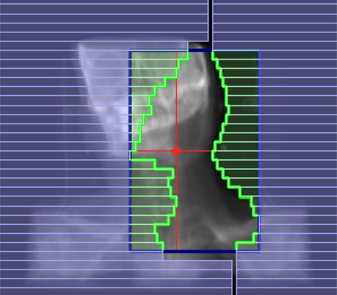
Figure 1. Multileaf collimators (MLCs).
Dynamic IMRT
In dynamic technique, the beam is kept on while the MLC leaves move to produce the desired intensity modulation throughout the treatment delivery. Starting with a certain field opening and then by narrowing or widening of MLC leaves, any field shape can be created with the varying intensity maps. Mostly by keeping one leaf stationary and moving the opposite leaf towards it, a wedge-shaped field can be obtained. Reference Stein, Bortfeld, Dorschel and Schlegel10
Step-and-shoot IMRT
One of the most commonly used modes of operation is the step-and-shoot or segmental MLC technique in which the modulation of intensity of beam in a treatment field is created by the exposure of a series of MLC-shaped discrete segmental fields. Reference Brahme11 The radiation beam is turned off when the MLC leaves are moving from one field segment to another, and is turned on only when the leaves reach and stop at the designated segment positions. Reference Boyer, Desobry and Wells12
Intensity-modulated stereotactic radiotherapy
In 1994, Cyberknife was introduced for stereotactic radio surgery. The system consists of a small light weight X-band linac with six degrees of freedom supported by a robotic arm coupled with an orthogonal pair of X-ray cameras. Reference Adler, Murphy, Chang and Hancock13 The cameras are able to image any change in patient setup and target motion during treatment, which are then fed to the robot to deliver radiation accordingly. Reference Murphy and Cox14 As Cyberknife does not have any fixed isocentre, radiation can be delivered in any direction in step–shoot manner. Reference Adler and Cox15
IMAT
Yu has developed an IMAT technique that uses the MLC dynamically to shape the fields as well as rotate the gantry in the arc therapy mode. Reference Yu16 The method is similar to the step-and-shoot in which each field is subdivided into subfields of uniform intensity and subfields are superimposed to produce the desired intensity modulation. However, the MLC moves dynamically to shape each subfield, while the gantry is rotating and the beam is on all the time.
VMAT
IMAT has been improved with the addition of variable gantry rotation speeds and dose rates, and was introduced as VMAT in 2007 to describe rotational IMRT delivered in a ‘single arc’. Reference Otto17 VMAT can provide highly conformal dose distributions and can significantly improve the IMRT delivery efficiency. The faster treatments reduce the effects of intra-fractional motion on both tumours and organs, and, of course, the shorter treatment times also increase patient throughput. The high plan quality and fast treatment delivery of VMAT are attractive, and it has been widely applied to many disease sites.
Materials and Methods
More than 450 patients have been treated with IMRT at our centre since July 2014 to till date. For this study, we had selected four major subsets. These included: (1) brain-3, (2) head and neck-3, (3) rectal-3 and (4) cervical-3 cancer patients. IMRT and VMAT plans were generated for comparison on Monaco planning system version 3.1 (Elekta Ltd, Crawley, UK) for Elekta synergy linac with clinically relevant planning constraints. Plan was created using a 6 MV photon beam. Planning parameters were kept same for both IMRT and VMAT. Plans were generated in such a way that 95% of planning target volume (PTV) receives 100% of prescribed dose. Critical organ dose kept as low as possible at the same time does not exceed the tolerance dose.
Case 1: brain cancer
Figure 2 shows an axial plan of a patient with meningioma planned with ssIMRT, dIMRT and VMAT. Total prescribed dose was 50 Gy in 25 fractions. The tolerance doses for organs at risk (OARs) were given in Table 1.

Figure 2. The isodose distribution of meningioma patient planed by (a) ssIMRT, (b) dIMRT, and (c) VMAT. Yellow colour was for isodose curve of 47·50 Gy.
Table 1. Planning objective for the critical structures

Case 2: head and neck cancer
Patients with primary head and neck cancers were treated at our centre. Figure 3 shows an axial treatment plan of a nasopharynx. Total prescribed dose was 50 Gy in 25 fractions for primary tumour volume and bilateral neck nodal volume. The tolerance doses for OARs were given in Table 1.

Figure 3. The isodose distribution of nasopharyngeal cancer planed by (a) ssIMRT, (b) dIMRT, and (c) VMAT. Brown colour was for isodose curve of 47·50 Gy.
Case 3: rectal cancer
Total prescribed dose was 50 Gy in 25 fractions. Figure 4 shows an axial treatment plan of a patient treated with IMRT and VMAT. Critical organs were rectum, bladder and left and right femoral heads. The tolerance doses for OARs were given in Table 1.

Figure 4. The isodose distribution of rectal cancer planed by (a) ssIMRT, (b) dIMRT, and (c) VMAT. Brown colour was for isodose curve of 47·50 Gy.
Case 4: cervical cancer
Patients of cervical cancer were planned with ssIMRT, dIMRT and VMAT (Figure 5). Prescribed dose was 50 Gy in 25 fractions. The OARs were bowel, bladder, rectum and femoral heads. The tolerance limits for OARs are given in Table 1.

Figure 5. The isodose distribution of cervical cancer planned by (a) ssIMRT, (b) dIMRT, and (c) VMAT. Brown colour was for isodose curve of 47·50 Gy.
Evaluation tools
Evaluation of the plans was performed by means of standard dose volume histogram (DVH). For PTV, D98% and D2% (doses received by the 98% and 2% of the volume) were defined for minimum and maximum doses. The homogeneity of the treatment plans was expressed in terms of (D2% − D98%)/D50% [homogeneity index (HI)] according to International Commission on Radiation Units and Measurements 83. Reference Yoon, Park and Shin18 An HI of zero indicates that the absorbed-dose distribution is almost homogeneous. The conformity of the plans was measured with a conformity index, CI98%, defined as the ratio between the patient volume receiving at least 98% of the prescribed dose and the volume of the PTV. Reference Feuvtet, Noël, Mazeron and Bey19 For OARs, the analysis included the mean dose (Dmean) and the maximum dose (Dmax). The integral dose (ID) of radiation delivered to the whole patient body was defined as ID [Gy⋯L] = D (Gy)⋯V (L), where D (Gy) is the mean dose delivered to volume V (L) (where L—litre). Reference Ślosarek, Osewski and Grządziel20 Doses relevant to OARs were evaluated according to the specific treatment sites.
Results and Discussion
All plans sufficiently respected the planning objectives and can be clinically accepted. Table 2 provide an overview of the numerical findings from an average DVH analysis on PTV, which are reported as mean values ± standard deviation (SD) to assess for the relative inter-patient variability. Dosimetric results for OAR for all the case sites were reported independently as the analysis was done for different sites (Tables 3–6). The results are very homogeneous within the different approaches with small SDs. Both delivery techniques, if considered from a clinical perspective, appear to be equivalent.
Table 2. Dosimetric results for the PTV

Table 3. Case1: head and neck

Table 4. Case2: brain

Table 5. Case 3: rectal

Table 6. Case 4: cervical

PTV
Target coverage was almost similar for all the techniques. VMAT plans resulted in a better conformity (CI98% = 0·965 ± 0·023) than dIMRT (CI98% = 0·939 ± 0·01) and ssIMRT plans (CI95% = 0·901 ± 0·038). The dose inhomogeneity in PTV was higher for ssIMRT plans with HI equal to 0·097 ± 0·015 when compared with dIMRT 0·095 ± 0·023 and VMAT 0·092 ± 0·0369. The average monitor unit (MU) (±SD) needed to deliver the dose of 200 cGy per fraction was 893·16 ± 340·6 MU for ssIMRT, 849·22 ± 191·5 MU for dIMRT and 868·70 ± 234·01 for VMAT. The average beam on time for VMAT plans (2 ± 1) was found to be significantly lower when compared with dIMRT (6 ± 2) and ssIMRT (11 ± 5).
OARs
All the techniques satisfied the planning objective for all OARs. The different characteristics of patients prevent the possibility to present an average conclusion and therefore the analysis was done separately for all the cases. The results are displayed in Tables 3–6. This study demonstrates that treatment techniques differ in terms of the treatment delivery time and overall plan quality. In comparison with ssIMRT, dIMRT and VMAT performed better in sparing OAR, particularly the lens, parotid glands, spinal cord and brain stem.
Case 1
The Dmax to the brain stem was reduced by 12% with dIMRT and 17% with VMAT. For spinal cord, the Dmax was also reduced by 1·3% with dIMRT and 1·2% with VMAT. There was a remarkable decrease in maximum doses of VMAT to the lens. The average maximum dose to the lens was reduced by 12·8% with dIMRT and 14·6% with VMAT. The mean dose to the ipsilateral parotid (right parotid) was reduced by 3·1% with dIMRT and 9% with VMAT.
Case 2
The average maximum dose to the lens was reduced by 20·4% with dIMRT and 39·1% with VMAT. The Dmax to the brain stem was reduced by 1% with dIMRT and 1·8% with VMAT. For optic chiasm, the Dmax was also reduced by 6·3% with dIMRT and 18% with VMAT.
Case 3
The average mean dose to the femoral head was reduced by 14·3% with dIMRT and 21·8% with VMAT. Bladder mean dose was increased by 6% with dIMRT and 9·4% with VMAT.
Case 4
The average mean dose to the femoral head was reduced by 22·9% with dIMRT and 8·5% with VMAT. Bladder mean dose was reduced by 5·7% with dIMRT and 3·2% with VMAT. Also, the rectum mean dose was reduced by 9·6% with dIMRT and 13·1% with VMAT.
Discussion
This study compared VMAT with dynamic IMRT and step-and-shoot IMRT for 12 patients of different sites. It indicated that given the same target dose coverage, VMAT is able to treat more efficiently with less damage to OAR. A study of head and neck cancer by Vanetti et al. Reference Vanetti, Clivio and Nicolini21 demonstrated that, given the same coverage, arc therapy offered better protection to OAR compared to IMRT similar to our study. Cozzi et al. Reference Cozzi, Dinshaw and Shrivastava22 conducted a planning study comparing VMAT with five-field conventional fixed-field IMRT in eight patients with cervical cancer. The results show similar target volume coverage with improved homogeneity and conformity with VMAT. OAR sparing (bladder and rectum) was significantly improved with VMAT with lower mean doses similar to our study. The study of Canyilmaz et al. Reference Canyilmaz, Uslu and Colak23 shows that the OAR sparing with VMAT is better than IMRT in case of high-grade gliomas similar to our study. The study of Studenski et al. Reference Studenski, Bar-Ad and Siglin24 also shows that the VMAT treatment delivery time is lower than the IMRT. The significant difference between VMAT and IMRT is the treatment delivery time.
There are some inherent limitations with this study. First, this study included very small sample size. To obtain more precise results and improve clinical decisions, studies with larger sample sizes are required. Second, it is extremely difficult to completely eliminate planner bias with the same strict planning objectives and calculation algorithms.
A major source of concern with VMAT and IMRT is the increase in low dose radiation to surrounding normal tissue, which potentially increases the risk of secondary malignancy. Reference Hall and Wuu25 It has been seen in a number of studies that induced risk of secondary malignancy with VMAT should be lower compared with IMRT as volume of normal tissues receives lower dose with VMAT. Reference Fogliata, Clivio, Nicolini, Vanetti and Cozzi26 Longer follow-up of patients treated with these techniques will be required to accurately quantify this risk. Finally, although there is evidence to show that VMAT gives better dose conformity and OAR sparing but cannot be considered as the universal solution for all clinical scenarios. Each case must be evaluated on an individual basis to select the most appropriate radiation technique that will give optimal results.
Conclusion
With the same PTV coverage, radiation therapy using VMAT and dIMRT can lower the dose to most OAR, minimise potential damage, and achieve better homogeneity and conformity compared with ssIMRT. ID to the patients with VMAT was also lower than the dIMRT and ssIMRT plans, which reduces the risk of secondary malignancy. The average treatment time for VMAT and dIMRT plans was shorter than that of ssIMRT, which can increase efficiency and relieve patient discomfort due to lack of movement for a prolonged time.
Acknowledgements
The authors would like to acknowledge the team of Radiotherapy Department for their co-operation. We would also like to acknowledge RIMS administration for the facilities provided in the department.
Financial Support
None.
Conflicts of Interest
There are no any conflicts of interest.


