


INTRODUCTION
Cancer treatment is a complex process which includes all aspects of diagnosis, treatment planning and treatment delivery. Accurate treatment delivery can be verified using in vivo measurements.Reference Kutcher, Coia and Gillin 1 There are some dosimeters available commercially like thermoluminescent dosimeters (TLD), PN junction-type diodes, or metal–oxide–semiconductor field-effect transistor (MOSFET) detectors and optically stimulated luminescence dosimeter (OSLD) for this purpose.
For a number of decades, TLD have been the passive detector of choice, able to perform in vivo dosimetry as well as remote quality assurance checks of radiation therapy delivery systems. Because of its long history, TLDs have been well characterised, making them reliable with relatively small margins of error. Their major disadvantage, which is the time required for readout, can be considerably decreased by a good choice of the TLD reader and a good methodology.Reference Kirby, Hanson, Gastorf, Chu and Shalek 2 , Reference Dam and Marinello 3 Semiconductor PN junction-type diodes have some advantages over TLD for in vivo measurements such as instant readout and reproducibility of signal. The physical and dosimetric properties of modern diodes have been studied and found satisfactory for use in the clinic.Reference Kumar, Sharma and Ravindran 4 – Reference Yorke, Alecu and Ding 7 However, they require handling of long cabling from treatment area to measurement station and they have cumbersome calibration with many corrections. MOSFET dosimeters provide for fast readout of the dose with permanent storage of information in the MOSFET.Reference Soubra, Cygler and MacKay 8 , Reference Lambert, Nakano, Law, Elsey, McKanzie and Suchowerska 9 Their small size makes them very useful for measurements in high-dose gradient regions, typically, for example, in brachytherapy. Their main disadvantage is their limited lifetime. 10
In recent years, new materials and methods have been proposed to improve passive radiation dosimetry in clinical applications and in radiation protection. One of these includes optically stimulated luminescence (OSL) to overcome a number of drawbacks inherent to the TLD and MOSFET. The OSL technique became a successful tool in personal and environmental radiation dosimetry, geological and archaeological dating, retrospective/accident dosimetry, and medical applications of radiation in diagnostic imaging as well as in radiotherapy in last two decades. The use of OSL for radiation dosimetry was first suggested in the 1950s and 1960s.Reference Antonov-Romanovskii, Keirum-Marcus, Poroshina and Trapeznikova 12 – Reference Sanborn and Beard 14 . However, the use of OSL for various dosimetric applications started in mid-1990s. The main obstacle at that time was the non availability of sensitive OSL phosphors.Reference Bhatt 11 – Reference Akselrod, Kortov, Kravetsky and Gotlib 15 Pulsed optically stimulated luminescence (POSL) technique for radiation dosimetry using anion-deficient carbon-doped aluminium oxide (Al2O3:C) has been developedReference Akselrod and McKeever 19 and is commercially implemented in LUXELTM technology (Landauer Inc., Glenwood, IL, USA). In 1998, the first commercial OSL dosimetry service based on Al2O3:C and the POSL technique (LuxelTM) was introduced by Landauer Inc.Reference McKeever, Akselrod and Markey 16 – Reference Yukihara and McKeever 22 There are several other OSL materials developed in recent decades but Al2O3:C is the only OSL material and is the most popular commercially available for various dosimetric applications in radiotherapy.
The dosimeter is generally characterised by some of the dosimetric quantities such as precision, accuracy, dose linearity, energy, dose rate and angular dependence. However, the response of dosimeter depends upon its physical form or dimension, construction and incidence angle of radiation beam. Al2O3:C-based OSL systems appear to possess the properties near to an ideal dosimeter, such as high sensitivity, high spatial resolution, availability in different shapes and sizes, no or few dependencies on beam parameters, capability to measure absorbed dose in real time for both photon and electron beams, and temperature independence for the ease of calibration and use.Reference Viamonte, Da Rosa, Buckley, Cherpak and Cygler 23 However, Al2O3:C-based OSL systems possess some disadvantages in that non-tissue equivalent material having an effective atomic numberReference Bos 24 (Z eff) of 11·28, requires a light protective environment to read and only single vendor of Al2O3:C material is commercially available for OSL-based dosimetry.
OSL utilises materials and electronic processes similar to thermoluminescence but interrogation of the detector is performed by light (ultraviolet, visible or infrared) instead of heat and emits a light signal; the wavelength of the emitted light is a characteristic of OSL material and the intensity of emitted light signal is proportional to the irradiation dose.Reference Edmund and Andersen 25 – Reference Yukihara, Yosimura, Lindstrom, Ahmad, Taylor and Mardirossian 29 High sensitivity, precise delivery of light, fast readout times, simpler readers and easier automation are the main advantages of OSL in comparison with TLD. OSL allows for re-reads of the detector multiple times while maintaining the precision, and yet it still can be used as an erasable measurement technique.
A number of papers have been published in past few years that describe the use of OSLDs for clinical measurements in radiation oncology.Reference Viamonte, Da Rosa, Buckley, Cherpak and Cygler 23 , Reference Takegami, Hayashi and Okino 30 – Reference Jursinic 41 JursinicReference Jursinic 31 published a very comprehensive study discussing the dosimetric properties of a commercially available OSL detector encapsulated in a light-tight plastic holder that is readout with a simple and efficient system Landauer Inc. Jursinic found their response to be independent of energy for megavoltage photons 6 and 15 MV. The dose sensitivity coefficient of variation of OSLDs from a batch of detectors was found to be 0·9%. The dose response was linear with absorbed dose over a test range of 1–300 cGy; >300 cGy a small supra-linear behaviour occurs. He demonstrated that the OSL signal stabilised after 8-minute post-irradiation.
Viamonte et al.Reference Viamonte, Da Rosa, Buckley, Cherpak and Cygler 23 also investigated some dosimetric characteristics of the same OSLD and readout system Landauer Inc. They found the detector response to repeated exposures to be within 2·5%, no energy dependence for 6, 10 and 18 MV photons, but ~4% lower response for Co60 γ rays. They demonstrated that the dose response was linear with a dose range 50–400 cGy. Their measurements with OSL detector and the ionisation chamber showed a very good agreement of <1% for relative output factor measurement. Yukihara and McKeeverReference Yukihara and McKeever 22 published a comprehensive review article on the fundamental and practical properties of OSLD in medicine. Pradhan et al.Reference Pradhan, Lee and Kim 42 also published a comprehensive review article on the fundamentals, materials available, practical dosimetric properties and radiation dosimetry by OSLDs.
OSL detectors are relatively new to medical dosimetry compared with TLDs. However, much characterisation has been done in recent few years on OSLD nanoDotTM (Landauer Inc., Glenwood, IL, USA) but it lacks the comprehensive characterisation of many mainstream TLD materials. The purpose of this work is to characterise commercially available OSL detector for use in certain clinical and dosimetric situations relevant to radiation dosimetry in radiotherapy. In the present work, a series of experiments were carried out using this OSL system to obtain the dosimetric quantities and the results obtained were compared with similar measurements carried out with an ionisation chamber.
MATERIALS AND METHODS
OSLD and readout system
The OSL system used in our study was commercially available OSL detection system, manufactured by Landauer Inc. The system consists of an OSL nanoDotTM dosimeter 43 as detector and InLightTM microStar® (Landauer Inc., Glenwood, IL, USA) reader 44 as readout assembly. The detectors consist of Al2O3:C (Landauer Crystal Growth Facility, Stillwater, OK, USA) encapsulated in a light-tight plastic holder with dimensions measuring 10×10×2 mm3 as shown in Figure 1a. During initial manual preparation to readout OSLDs, these plastic holders are placed into larger holder and then placed into the reader sliding drawer, shown open in Figure 1b. During readout, inside the reader, the plastic case over the detector is slid open and the detector’s active part Al2O3:C chip is optically simulated using light-emitting diodes (LEDs). The microStar reader uses an array of 36 LEDs for stimulation of nanoDotTM. One of two exposure levels is automatically selected depending on the dose level determined by the software. In ‘low-dose’ mode, all 36 are illuminated, whereas in ‘high-dose’ mode only six LEDs are illuminated.Reference Dunn, Lye, Kenny, Lehmann, Williams and Kron 40 In present study, all nanoDotsTM were exposed to levels deemed ‘high’ by the software and were therefore readout in high-dose mode with a stimulation time of about 1 second. The microStar OSL reader operates in the continuous wave optically stimulated luminescence (CW-OSL) mode. The CW-OSL mode of stimulation considered to be the most sensitive mode of OSL, because the intensity of the emitted signal is the highest during a stimulation and there is no restriction on the duration of a stimulation or recording for an optimisation of the signal-to-noise ratio as compared with other stimulation modes, that is, linearly modulated OSL, POSL.Reference Palan 45 When green light from LED is incident on Al2O3:C chip, the trapped electrons get exited (the number of trapped electrons proportional to the exposed dose), and emits blue luminescent light as a result of de-excitation of electrons. The photomultiplier tube that is installed in reader counts the number of blue luminescent light photons, which is proportional to the exposed dose in the reader. All the readouts were performed after a time delay of 10 minutes following irradiation of dosimeters to avoid transient signal in all of the OSLDs as was suggested by Jursinic.Reference Jursinic 31
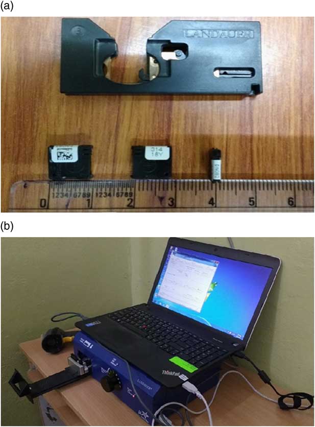
Figure 1 (a) Photograph of InLight nanoDot™ optically stimulated luminescence dosimeter form Landauer Inc., with large holder (above) to place the dosimeter for readout. (b) Photograph of the Inlight microStar® reader system from Landauer Inc. Notes: (a) Three nanoDots placed in different orientation showing (left) back, (middle) front and (right) side on profile of closed dosimeter. (b) Closed dosimeter dimensions are 10×10×2 mm3. The complete reader system consists of a barcode scanner to facilitate record keeping and data entry, a loader to load dosimeter in reader for readout and a laptop to show readout result and record keeping of data.
Therapy units and phantom
In the present study, Bhabhatron-II TAW (Panacea Medical Technologies Pvt. Ltd, Bengaluru, India) unit cobalt-60 telecobalt radiation was used for most of the measurements carried out. Varian Clinac-iX linear accelerator (Varian Medical Systems, Palo Alto, CA, USA) was also used for 6 and 10 MV energy X-ray photon beams to study dose rate and energy dependence. All irradiations performed in a 30×30 cm2 custom made acrylic solid slab phantom, which is placed on the couch of the machine. The solid water phantom slab having a slot for accommodating parallel plate chamber is filled with a little amount of tissue equivalent material, that is, paraffin at level of phantom surface and a slot was fabricated and filled with paraffin in a size comparable with size of nanoDotTM, for accommodating the OSL nanoDotTM in the phantom, placing the detectors in a solid slab phantom without incurring air gaps. The use of this method avoided the need for the slabs of solid water (Standard Imaging, Madison, WI, USA) to be machined to fit the various detectors. The total thickness of the slab phantom was kept at 10 cm beyond the point of measurement, which was sufficient to provide adequate backscattering for the photon beam used in this study.
Experimental set up condition
Unless otherwise mentioned, most of irradiations were carried out using an source-to-surface distance (SSD) set up (80 cm for Co60 and 100 cm for linear accelerator beams) with a 10×10 cm2 field size and the irradiation platform is perpendicular to the incident radiation beam. Before each irradiation session, the SSD was carefully monitored and verified with the optical distance indicator. The dosimeter in the phantom was then positioned at the phantom surface and aligned with the central axis of the teletherapy machine. OSL detector is placed at either 0·5 or 5 cm depth in phantom with an appropriate build-up of acrylic solid slab phantom as suggested by Werner et al.Reference Werner, Das, Khan and Meigooni 46 in a flat homogeneous phantom for Co60 and high-energy beams. In our experiments, a high level of precision for high-energy beam irradiation was achieved by placing nanoDotTM with appropriate build-up thickness and with full scatter conditions for full phantom geometry. The dosimeters are then irradiated to a known dose. After each irradiation, the dosimeter group was read in one session to reduce statistical uncertainty associated with the reader. Each dosimeter was read three times consecutively to reduce the measurement uncertainty. The apparent reading of each individual dosimeter was taken as the average of the three readings performed on it consecutively. When absolute doses were of interest, absolute dose was measured using a TM30013 Farmer type [Physikalisch Technische Werkstätten (PTW), Freiberg, Germany] cylindrical ionisation chamber in acrylic solid slab phantom.
Response studies for Al2O3:C
OSL detectors were exposed to identical doses of 50 cGy irradiated in Co60 telegamma beam. Eight detectors were used to evaluate the inter-detector response variation. Absolute dose was also measured using a TM30013 Farmer type PTW ionisation chamber in acrylic solid water slab phantom. Average OSLD response was compared with practically measurable ‘gold standard’ ionisation chamber measurements.
One of the important characteristics of a dosimetric system is energy response due to the fact that the energy absorbed by the material (detector) is usually proportional to the dose absorbed. Dosimeter system may exhibit energy dependence due to higher atomic number (increase in detector response at low-energy beams), different energy beams have different scattering properties which can result in slight change in detector response indirectly during measurement. Detectors calibrated in only a particular radiation field generally Co60 as reference beam, any deviation from calibrated reference beam may result in significant change in detector response. It is difficult to develop an ideal dosimeter that is tissue equivalent and energy dependent over the entire clinical energy range used in radiotherapy. Thus, the suitability of this commercial OSL system for clinical use in radiotherapy may also be dependent on the variation in the response with beam energy, needs to be investigated. Further, there is variability found in the literature for energy dependency of OSLD which needs to be analysed. In this present study, energy dependence of OSL was investigated for Co60, 6 and 10 MV beams, delivering an identical dose of 50 cGy each at dose maximum depth (d max) in phantom with a 10×10 cm2 field size at source-to-axis distance (SAD) set up for all three energies. Further, the dose rate dependence of OSL detector is evaluated for dose rates of 200, 400, 600 MU/minute in linear accelerator by delivering a dose of 50 cGy at SAD at d max in with 6 MV energy X-ray photon beam. Energy and dose rate dependency measurements aimed to provide a corrected dose value, after calculating a calibration factor by comparing dose received in a particular radiation field to that of Co60 for reference.
OSL response with given dose is investigated for doses ranging from 50 to 400 cGy. Irradiations of dosimeters were carried out to known doses in reference Co60 beam at 0·5-cm depth in phantom. The response of a dosimeter should be independent of the field size and depth. However, it is recommended to check the dosimeter response with these dependences before using it for dosimetry. To analyse OSL response with the field size and depth, nanoDotsTM were irradiated with fields of 4×4, 10×10 and 30×30 cm2 and depths of 1·5, 5, 10 and 14 cm in Co60 beam. Before a measurement session, for each field size/depth combination, the irradiation time was determined such that the delivered dose would be as close as possible to 25 cGy, using the established baseline phantom percentage depth dose (PDD) curves traceable to British Journal of Radiology Supplement 25 data. 47 OSL nanoDotsTM were then irradiated with these calculated irradiation time.
Angular response is an important dosimetric parameter of the dosimeter and must be analysed before use in in vivo dosimetry and patient quality assurances for multi-field treatments in radiotherapy. The response of the dosimeter varies with radiation incidence angle depending on their various physical parameters such as construction, physical size, shape and energy of incident radiation. In our study, because the construction of OSLDs from Landauer consists of a thin disk of Al2O3:C-coated material encased in plastic with a small air gap, the irregular geometry mandates that angular dependence is an important characteristic to determine. The magnitude of incidence beam angularity effect was evaluated by measuring dose on central axis of the beam at the depth of maximum dose with along with investigating build-up thickness effect in rectangular geometry phantom. The dosimeter angular response of OSLD was studied in solid slab phantom at various gantry angles ranging from 90 to 270° relative to the axis of gantry rotation, at an interval of 30°, with two different experimental set up having a 0·5 cm build-up of solid slab phantom placed over detector and without build-up, respectively. The responses of OSLD at any angle normalised to response of OSLD at 0° gantry angle, where the radiation incidence was perpendicular to detector.
During multiple readouts of OSL for dose were reanalysed the subsequent readout results in a decrease in signal. In present study, Landauer InLight microStar® reader OSL system was used in standard operating mode. After single irradiation to a known dose subsequent readouts were performed of nanoDotsTM. Long-term fading of the signal is an important parameter of the dosimeter for the use in dosimetric audits, permanent dose record and for the utility of dosimeter in periodic dose assessment applications. For this purpose, OSLDs were irradiated to a dose of 50 cGy. The first reading of the OSL nanoDotsTM was performed, taken as reference and thereafter, the readouts were performed weekly and monthly.
A set of radiation dosimetry measurements were carried out using OSL detectors and the results were compared with ionisation chamber measurements. These measurements were aimed to check the accuracy of OSLDs for routine relative dosimetry in radiotherapy. For this purpose, PDD curves were measured with OSLDs at a depth ranging from 0·0 to 14 cm in solid slab phantom for Co60 beam. The relative output factors were also measured with six different field sizes, ranging from 4×4 cm2 to 22×22 cm2. Ionisation chamber measurements were performed with TM04102 PTW Markus parallel plate ionisation chamber (PTW, Freiburg, Germany) for PPD measurement and TM30013 PTW Farmer type cylindrical ionisation chamber is used for output factor measurements, under the same experimental condition.
RESULTS AND DISCUSSION
Inter-detector response
This study investigated dosimetric characteristics of OSLDs in megavolt energy photon beam and some relative dosimetric quantities were also measured. The inter-detector variation of OSL detector was found to be within 3·44% SD, with coefficient of variation of 0·035. Mrcela et al.Reference Mrčela, Bokulić, Izewska, Budanec, Fröbe and Kusić 37 investigated inter-detector variation for irradiating at various identical doses, that is, 1·6% for 50 cGy and 1·3% for 100 cGy. However, the reproducibility of OSL InLightTM Dot irradiated eight times×100 cGy with accumulating dose from each irradiation was found to be 3·5% and it was observed only 1% for OSL Dot optically bleached (illuminated to light to remove some of electron trap for optical resetting of dosimeter) before each irradiation. Another author Jursinic showed for six InLightTM/OSL Dot dosimeters subjected to identical dose of 100 cGy had a coefficient of variation of 0·93%. In addition to that, an OSLD was repeatedly exposed, read and then optically annealed to six times provided, an analysis of six data points and had a coefficient of variation of 0·63%.Reference Jursinic 31 However, it was later shown for 17 individual nanoDotsTM that were new and never irradiated, that they had unique sensitivity (coefficient of variation 5·1%) to low dose and unique supra-linearity (coefficient of variation 28%). In addition, these characteristics were shown to change with accumulated dose.Reference Jursinic 35 Apart from high accumulated doses, which lead to a drop in OSL sensitivity, the size of the dosimeter, reduced in case of nanoDotsTM than in Dot dosimeters, was considered as a contributing factor in the large deviation in coefficient of variation in both published results. It has been reported by Jursinic, for a sample of 78 new nanoDotsTM, the range of their relative intrinsic sensitivity was found within 0·92–1·09 due to the inhomogeneous composition of the OSLD disc.Reference Jursinic 41 Viamonte et al. showed 4·2% (1 SD) inter-detector variation of a batch of 165 OSL Dot detectors exposed to 50 cGy irradiation suggesting good stability of the system and implied that detectors from a given batch might be used with a single calibration factor depending on the level of precision required. Our results are consistent with the findings of Mrcela et al.Reference Mrčela, Bokulić, Izewska, Budanec, Fröbe and Kusić 37 and Schembri and Heijmen.Reference Schembri and Heijmen 48 Schembri and Heijmen who investigated inter-film variations in 228 OSL films for a fixed dose of 200 cGy in six measurement sessions and found a variation in the range of 1–3·2% (1 SD). They exposed 125 OSL films to doses ranging from 5 up to 202 cGy irradiation in a 6 MV photon beam under identical conditions of irradiation and suggested that on average, the spread in readings for low doses <30 cGy was larger than for higher doses and showed a decrease in SD of 0·3%/100 cGy through linear regression of data points. There was variability found in the literature as far as delivered doses are concerned ranging from 25 to 200 cGy. This can also be considered as a minor contributing factor variation found in the coefficient of variation in the literature. However, the present study utilised 50 cGy identical doses for performing the experiments.
In conclusion, based on our experimental results and comparing them with other studies, we recommend minimum threshold of delivered dose of 50 cGy for calibration studies of OSL dosimeters, because inaccuracy in measurements may be significant and the dosimeter is not going to serve the purpose. More than 50 cGy delivered dose for the OSL calibration studies will increase accumulated dose to OSL dosimeter without any significant improvement in accuracy of measurements.
Further, an average response of the OSLDs was evaluated 0·982 relative to the IAEA TRS-398Reference Andreo, Burns and Hohlfeld 49 calculated absolute dose using an ionisation chamber. The maximum percentage deviation in an OSLD was found to be 4·5%, which is low relative to the ionisation chamber measurement. A possible explanation of an under response of the OSLD observed, could be the result of inherent scatter conditions within the detectors due to the ~0·85 mm of air gap on each side, between the aluminium oxide (as an active detector material) and plastic casing.
Energy response
There was a difference observed in response to Co60 compared with 10 MV photon beams of ~3% as given in Table 1; however, it was found within experimental uncertainty. Our results for energy dependency suggested that there is an energy independent response of OSLD in Co60 to 10 MV photon beam. Dunn et al.Reference Dunn, Lye, Kenny, Lehmann, Williams and Kron 40 performed an energy dependency test for a similar type of OSL nanoDot, this showed little dependence on energy. The largest variation was in response to 6 MV for photons and for electrons was attributed to 1·2% for Co60 and 1·6% for 20 MeV beams, respectively. Two different Monte Carlo studies performed by Mobit et al.Reference Mobit, Agyingi and Sandison 50 and Chen et al.Reference Chen, Wang, Chen, Tang and Liu 51 on Al2O3:C found a decrease in relative response of 2% in 15 MV and 6–24 MV photons, was determined to be 1%, respectively. Both studies concluded that the independent response of OSLD is a function of energy. However, Schembri and HeijmenReference Schembri and Heijmen 48 found a difference of ~4% between 6 and 18 MV photon beams in OSL films of Al2O3:C. Previous authorsReference Viamonte, Da Rosa, Buckley, Cherpak and Cygler 23 , Reference Jursinic 31 performed experiments with the OSL InLight Dot dosimeters, unlike this present study that used OSL nanoDotTM dosimeters. However, the general geometry, construction, and casing material are similar to the InLight nanoDotTM. The Dot measures 24×12×2 mm3 with the aluminium oxide disk having a 7-mm diameter, whereas nanoDotTM measures 10×10×2 mm3 with the oxide disk having a 5-mm diameter.Reference Kerns, Kry, Sahoo, Followill and Ibbott 52 However, Jursinic found no energy dependence between 6 and 15 MV photon beams within experimental uncertainty, which is consistence with our results. However, Viamonte et al.Reference Viamonte, Da Rosa, Buckley, Cherpak and Cygler 23 found similar results for 6 and 18 MV beams suggesting a single calibration factor in high megavolt beams; however, there was a clear difference in response to Co60 compared with megavolt beams of ~4% requiring an energy correction factor for dose assessment at higher energies for detectors calibrated in Co60 energy. In contrary to that for high-energy photon beams, Yukihara et al.Reference Yukihara, Mardirossian, Mirzasadeghi, Guduru and Ahmad 32 reported OSLD response for 18 MV was (0·51±0·48)% of the response for the 6 MV photon beam. However, their results for the response of OSLD in a range of 6–20 MeV electron beams, for ‘uncorrected data’ OSLD response is on average 1·9% higher than the response to the 6 MV photon beam, demonstrated need of a fixed correction factor. Both the studies by Viamonte et al.Reference Viamonte, Da Rosa, Buckley, Cherpak and Cygler 23 and Yukihara et al.Reference Yukihara, Mardirossian, Mirzasadeghi, Guduru and Ahmad 32 normalise the data to response of OSLD for Co60 and 6 MV photon beam, respectively. Yukihara et al. eliminated the machine output variation uncertainty in measurements by dividing OSLD response by the machine calibration factor. However, Yukihara et al. investigations were made by circular discs measuring 7 mm in diameter with a Risø TL/OSL-DA-15 reader (Risø National Laboratory, Denmark) was used to read OSL signal. Energy dependence of Al2O3:C has been studied several times in the past but the results are varied, the reasons for the differences reported in the literature is unclear. However, in our study the OSLD was calibrated in to a reference Co60 beam, any deviation in beam quality for each measurement was expected and was found within experimental uncertainty, suggesting response of the OSLD is energy independent.
Table 1 The relative energy response of optically stimulated luminescence (OSL) detectors as a function of incident photon energy for Co60, 6 and 10 MV beam

Note: The response is normalised to the reading for Co60. Three detectors were used at each energy setting.
Abbreviation: OSLD, optically stimulated luminescence dosimeter.
Dose rate response
The response of OSLD with dose rate was observed in a clinical treatment range from 200 to 600 MU/minute in 6 MV beam and the response of OSLD was found to be independent of dose rate. JursinicReference Jursinic 31 performed measurements by varying dose-per-pulse ranging from 53·4 Gy/second to 3,208 Gy/minute achieved by changing in source to detector distance delivering a dose of 100 cGy at SAD at d max in 6 MV beam and showed no change in OSL InLightTM Dot dosimeter response for a large 388-fold change in dose-per-pulse. Schembri and HeijmenReference Schembri and Heijmen 48 also tested the dose rate dependency of OSL films by delivering an identical dose of 200 cGy at SAD at d max in 6 MV beam and found that the deviations from the mean OSL response for all films remain within ±1%. Viamonte et al.Reference Viamonte, Da Rosa, Buckley, Cherpak and Cygler 23 and Yukihara et al.Reference Yukihara, Mardirossian, Mirzasadeghi, Guduru and Ahmad 32 also showed the response of OSLD independent of dose rate up to 400 cGy/minute in Co60 beam and 600 MU/minute in 6 MV photon beam in their respective studies. However, Yukihara et al. also investigated dose rate check with 1,000 MU/minute in a 9 MeV electron beam and the overall OSL response was found within ±1%. Sharma et al.Reference Sharma and Jursinic 39 reported no dose rate effect on OSLD in high-dose rate brachytherapy measurements ranging from a change in dose rate of 3·5–0·14 cGy/second at 2 and 10 cm, respectively. Our findings were inconsistent with all the above studies for dose rate dependency suggesting that there was no effect of dose rate on response of OSLD.
Dose response
Our experimental results for dose linearity showed that OSL dosimetry provides a good linearity until ~250 cGy of dose with a coefficient of determination (R 2) value 0·997 but after that OSL dose shows supra-linear response at higher doses as shown in Figure 2. One other similar study, performed by JursinicReference Jursinic 31 reported a linear response with absorbed dose over a test range of 1–300 cGy; >300 cGy a small supra-linear behaviour occurs. Our supra-linear response is in agreement with a few similar studies reported by Reft,Reference Reft 34 Jursinic,Reference Jursinic 35 Mrcela et al.Reference Mrčela, Bokulić, Izewska, Budanec, Fröbe and Kusić 37 and Schembri and Heijmen.Reference Schembri and Heijmen 48 They observed dose linearity up to around 200 cGy followed by an increase in OSL sensitivity. A large number of charge transfer reactions take place during irradiation and stimulation of an OSL material, which is a complex phenomenon. However, an increase in OSL sensitivity at higher doses is explained by an increase in deep and intermediate electron trap concentrations in a competitive manner with accumulated doses. The shift in the concentrations of deep and intermediate electron traps impacts on the magnitude of supra-linearity at higher doses.
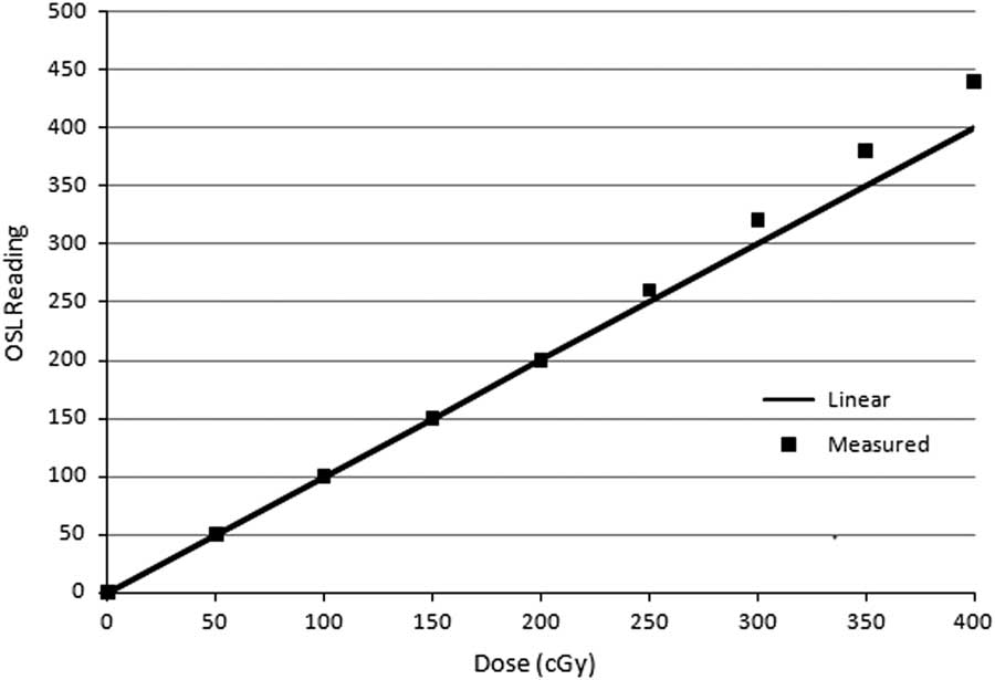
Figure 2 The dose linearity curve showing measured response of optically stimulated luminescence dosimeter (OSLD) as a function of delivered absorbed dose. Note: The solid line shows linear dependency on dose based on the response of OSLD data upto 400 cGy. Abbreviation: OSL, optically stimulated luminescence.
Field size and depth dependency
OSLDs were irradiated with a Co60 beam using three different field sizes of 4×4, 10×10 and 30×30 cm2, and four depths of 1·5, 5, 10 and 14 cm. OSL responses (counts/delivered dose) relative to the overall mean response for all fields and depths were observed within ±3·5%, which was within experimental uncertainty. Mrcela et al.Reference Mrčela, Bokulić, Izewska, Budanec, Fröbe and Kusić 37 reported variation in OSL sensitivity with field size <1%. Yukihara et al.Reference Yukihara, Mardirossian, Mirzasadeghi, Guduru and Ahmad 32 investigated the field size dependency and the maximum variation was ±1% as compared with ionisation chamber measurement for four different field sizes ranging from 5×5 cm2 to 30×30 cm2 irradiated with 200 MU at a depth of 10 cm in water 6 MV beam. Our results are in agreement with Schembri and HeijmenReference Schembri and Heijmen 48 who found deviations in the overall mean response of OSL films within 2·5% when comparing different field sizes, at various depths in the phantom.
Angular response
The angular response was studied for OSLD with 0·5 cm build-up of solid slab phantom placed over detector and without using build-up, respectively, in a Co60 beam and the results of angular correction factors are shown in Figure 3. The maximum deviation of OSLD was found to be, 8% relative to the response of OSLD at gantry angle 0° with build-up, the maximum deviation observed was an under response of OSLD by 38% without build-up set up, respectively. The results of the test of normal incidence of radiation on detector for without build-up observed an under response of measured dose due to lack of build-up. This supports the findings of Jursinic and YahnkeReference Jursinic and Yahnke 36 in that the use of the detector without a build-up cap is the appropriate way to measure dose on the surface of the patient but it is an unsuitable method to measure dose at other depths in the patient. However, placing the detector on the surface of a patient will perturb dose delivered by the attenuation and scatter of beam. The results of the OSLD showed an under response of the dosimeter at angles approaching 90–270° in both with and without build-up set up studies. In our experiment, a drop in signal at the 90–270° points is due to the limitations in phantom and dosimeter geometry at these extreme angles. This experimental method has the limitation of using a rectangular geometry phantom in which dose to a point in the rectangular phantom changes with the incident angle of radiation. At more oblique angles, the dose decreases due to attenuation of the beam passing through the edge of the phantom. Thus, the angular dependence noticed at the extreme angles can simply be ignored due to experimental uncertainty. Cylindrical phantoms were best suited for angular dependency check with no angular dependency and eliminating above-mentioned experimental uncertainty. JursinicReference Jursinic 41 performed a study in which nanoDotsTM were irradiated in cylindrical, cubical or rectangular phantoms in a 6 MV beam and showed a maximum angular dependence of 1% or less at an incidence angle of 90°. In our study, the results for angular dependency of nanoDotsTM in a Co60 beam, disagree with Jursinic, the possible reason for discrepancy is the use of a cylindrical phantom with relatively small dimensions and in the 6 MV beam the gantry was stationary and the phantom was rotated for the measurements. However, our measurements were performed in a rectangular phantom in the Co60 beam and the gantry was rotated, whereas the phantom was stationary. The findings of our data were consistent with two Monte Carlo simulation studies performed on OSL nanoDotsTM by Lehmann et al.Reference Lehman, Dunn and Lye 53 and Kerns et al.Reference Kerns, Kry, Sahoo, Followill and Ibbott 52 and suggested a small angular dependency of OSLD due to the variation observed in the response of OSLD when irradiated with the incident photon beams parallel to the plane of the dosimeter (0°) to the response of OSLD when irradiated with the incident beam at any other angle to the plane of the dosimeter. Measurements performed by Lehmann et al. were also made in a rectangular phantom and they reported a small angular dependence of ~2%, which needs to be considered for measurements involving other than normal incident beam angles. Kim et al.Reference Kim, Chung and Shin 54 showed a 70% angular dependence when irradiation is done in a highly asymmetric field that occurs on the surface of a phantom. Kerns et al.Reference Kerns, Kry, Sahoo, Followill and Ibbott 52 reported a drop in nanoDotTM response at 90° versus 0° incident angle of the radiation beam for 6 and 18 MV, this was found to be 4 and 3%, respectively. Their Monte Carlo simulations at 6 MV showed similar results to their experimental values. He suggested that the larger size of Dot dosimeter contributes more to the increase in angular dependency than the small size OSL nanoDotTM dosimeter.
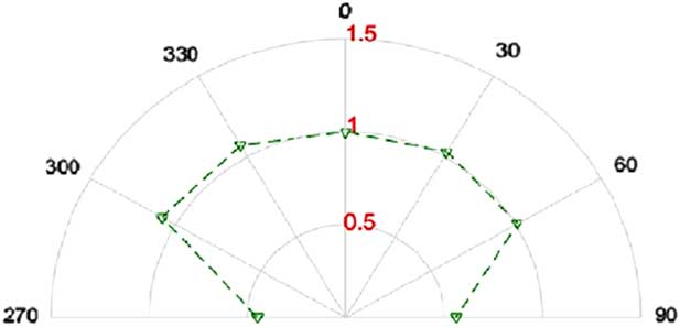
Figure 3 Angular response curve for optically stimulated luminescence dosimeter (OSLD). All dosimeters were irradiated in a 10×10 cm2 field, at a depth of 0·5 cm. Notes: The angular response of OSLD measured at gantry ranging from 90 to 270° relative to the axis of gantry rotation, at an interval of 30°. The responses of OSLD at any angle normalised to response of OSLD at 0° gantry angle.
Signal depletion
The re-readout property of OSL dosimeter is an invaluable advantage. This allows multiple readings for better statistical results and a permanent record that can be read again much later on if need be. However, each readout of the dosimeter depletes the amount of trapped charge by a small fraction. For a comprehensive approach, we have evaluated the depletion in signal per readout. The decrease in signal was found to be 0·29% per readout for OSL nanoDotTM. A similar study using OSL Dot dosimeters was performed by Mrcela et al.Reference Mrčela, Bokulić, Izewska, Budanec, Fröbe and Kusić 37 and demonstrated a reading uncertainty of a single dosimeter was found to be 0·6% delivering 50 cGy with one irradiation of each dot. JursinicReference Jursinic 31 showed that the luminescence signal is reduced by ~0·2%.
Long-term fading
The long-term fading of signal of the dosimeter was studied and was found to be 1·4% in 1 week. The signal fading data of three dosimeters were recorded and shown in Figure 4, which shows that the fading behaviour was very much consistent between dosimeters. In a long-term study, the response showed a signal fading of ~1·8% after 37 days compared with 1 day post-irradiation. Dunn et al.Reference Dunn, Lye, Kenny, Lehmann, Williams and Kron 40 showed that the nanoDotsTM lost ~2·5% over 30 days if the readout time was normalised to 2 days following irradiation. Mrcela et al.Reference Mrčela, Bokulić, Izewska, Budanec, Fröbe and Kusić 37 reported a 4% lower response post-58 days when first readout was taken 1 hour after the irradiation. Viamonte et al.Reference Viamonte, Da Rosa, Buckley, Cherpak and Cygler 23 showed a drop in signal of about 2% within the first 5 days after irradiation. Beyond 5 days, the signal was stable up to 21 days post-irradiation. One of the other studies of long-term fading between 3 weeks by Schembri and HeijmenReference Schembri and Heijmen 48 measured fading of OSL films, was <1·8%. However, their first reading for normalisation was not taken until day 17, as the OSL films had to be sent away for reading. Our results are in agreement with all the above-mentioned studies. However, small variation were observed due to different types of OSLDs and time elapsed between taking first readout after irradiation because the signal decays very fast in an exponential manner for the first few minutes after the irradiation. The long-term fading property study showed that the dosimeter is a suitable for keeping a permanent dose record. The results of this present study supports the statement of Dunn et al.Reference Dunn, Lye, Kenny, Lehmann, Williams and Kron 40 that the fast readout, accuracy and reusability of nanoDotTM dosimeters make the dosimeter is a viable replacement for TLD in large-scale dosimetry operations for dosimetry audits. However, in the present scenario, these commercial dosimeters are more expensive than the TLDs.
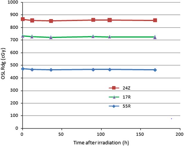
Figure 4 Post-irradiation fading response of optically stimulated luminescence (OSL) dosimeter in a week period. Note: Three dosimeters were used identified as 24Z, 17R, 55R, the three digits of unique alphanumeric code of dosimeter.
PDD and relative output factor measurement
The PDD curves for Co60 beam measured using OSL detectors and a Markus ionisation chamber are shown in Figure 5. There was an inherent build-up of 0·42-mm thick plastic cover in the case of OSLD and 0·2 mm in the case of the ionisation chamber measurements, respectively. The OSL curve shows a good agreement with the ionisation chamber measurements, at greater depths, the OSL measurements were within ±1% relative to ionisation chamber measurements. Our results are in agreement with Yukihara et al.Reference Yukihara, Mardirossian, Mirzasadeghi, Guduru and Ahmad 32 who reported that maximum relative errors were measured until a depth of 15 cm and, were found to be 1·7% for 6 MV photon beam (d=13 cm) and 0·7% for 18 MV photon beam (d=2 cm) as compared with commissioning data acquired with Scanditronix/Wellhofer CC13 (Radiation Products Design Inc., Albertsville, MN, USA) ionisation chambers measurements. Further, the relative output factors were also measured using OSL detectors and Farmer type ionisation chamber, which are presented in Figure 6. The variation in OSL measurements for all field sizes considered were found to be within ±3% relative to ionisation chamber measurements. Our findings are in agreement with Viamonte et al.Reference Viamonte, Da Rosa, Buckley, Cherpak and Cygler 23 who demonstrated a difference of <1% in relative output factors measurement for Co60 beam with an NE2571 (PTW, Freiburg, Germany) ionisation chamber placed at a depth of 5 cm in a solid water phantom.
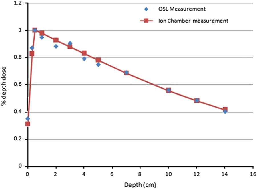
Figure 5 Showing comparison of percentage depth dose (PDD) curves in solid water for 10×10 cm2 field at source-to-surface distance 80 cm in a Co60 beam upto 14·0-cm depth. Note: The solid line shows PDD curve measured using a Markus parallel plate ionisation chamber for the irradiation conditions and energy. Abbreviation: OSL, optically stimulated luminescence.
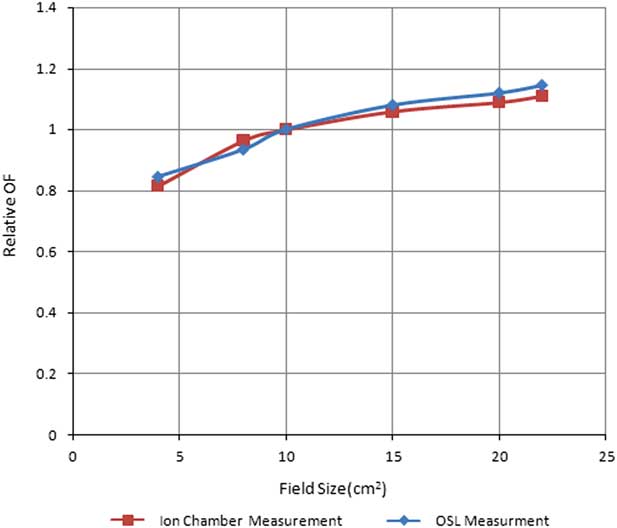
Figure 6 Showing comparison of relative output factor curves measured using optically stimulated luminescence (OSL) dosimeters and a Farmer type cylindrical ionisation chamber, in solid water for field size ranging from 4×4 cm2 to 22×22 cm2 in a Co60 beam.
The literature reports several studies on Al2O3:C OSL material. Most of them were performed on single crystal of Al2O3:C,Reference Akselrod, Kortov, Kravetsky and Gotlib 15 OSL film stripsReference Schembri and Heijmen 48 and in house-developed powder and discs of Al2O3:C, OSL LuxelTM dosimetersReference McKeever and Akselrod 18 /OSL InLightTM DotReference Viamonte, Da Rosa, Buckley, Cherpak and Cygler 23 , Reference Jursinic 31 , Reference Yukihara, Mardirossian, Mirzasadeghi, Guduru and Ahmad 32 dosimeters from Landauer Inc. Schembri and HeijmenReference Schembri and Heijmen 48 used Al2O3:C-based OSL film strips and Viamonte et al.,Reference Viamonte, Da Rosa, Buckley, Cherpak and Cygler 23 Mrcela et al.Reference Mrčela, Bokulić, Izewska, Budanec, Fröbe and Kusić 37 used OSL Dots with the microStar reader system in their studies, respectively. In contrast, Yukihara et al.,Reference Yukihara, Mardirossian, Mirzasadeghi, Guduru and Ahmad 32 used an automated Risø TL/OSL-DA-15 reader to carry out experiments and before irradiation, the dosimeters were optically illuminated. However, to date the OSL InLight nanoDotTM from Landauer Inc.,Reference Jursinic and Yahnke 36 – Reference Jursinic 41 , Reference Kerns, Kry, Sahoo, Followill and Ibbott 52 – Reference Kim, Chung and Shin 54 is relatively new for use in in vivo radiation dosimetry and was used in the present study with a InLightTM microStar® reader as OSL readout assembly. Despite of the fact that the OSL Al2O3:C material remains the same as well as the general geometry, construction, outer covering material, there is variability found in literature for experimental set up condition. This variability found in terms of irradiation dose, beam energy and phantom geometry, etc., irradiation history of detector, that is, the use of new/reuse of dosimeters with accumulated dose for experiments/various optical bleaching methods applied before experimental irradiation of OSLD to eliminate any background signal and difference in readout methodologies with different types of readout assembly used for readout may result in alteration in some of the characteristics of OSL dosimeter. This is the possible reason for the variability found in literature with respect to present study for few characteristics, for example, angular and energy dependency of the Al2O3:C-based OSLD.
Conclusion
The dosimetric characteristics of the commercial OSL system were studied. The results demonstrate good accuracy and precision as compared with the ionisation chamber. It was observed that the OSL response is energy and dose rate is independent. Our experimental results for dose linearity show a linear OSLD response until ~250 cGy, which was just above the normal clinically relevant dose range in radiotherapy but above this dose, a supra-linear behaviour of OSLD was observed. Thus, dose evaluation by OSLD at high doses requires a non-linear calibration factors or a high-order polynomial fits need to be applied in evaluation of delivered dose. This study suggests the need to use appropriate build-up during surface dose measurements in multi-field angular beam delivery in radiotherapy for accurate dose estimation, as insufficient build-up may result in inaccurate dosimeter readings. Based on the results of this study, the linear dose response in clinically relevant dose range and the high sensitivity of OSL dosimeter and the ease of use and stability of OSL system, make it a good choice of dosimeter for in vivo dosimetry in radiotherapy. The variation in the response of OSLD for measuring PDD and relative output factors were measured and compared with ionisation chamber absolute measurements, which were found very close to ionisation chamber measurements. This shows that OSLD is a good relative dosimetric tool which can be used as a relative radiotherapy dosimeter in the future.
Acknowledgement
The authors would like to thank Senthil Kumar for his support to provide linear accelerator irradiation in the study at Bhagwaan Mahavir Cancer Hospital and Research Centre, Jaipur. The authors has no financial support for the study.
Conflicts of Interest
The authors declare that they have no conflicts of interest.


