Introduction
Gamma Knife stereotactic radiosurgery (GKSRS) offers treatment with highly focused gamma rays to eliminate deep-seated tumours without damaging surrounding healthy tissue. Small tumours of dimension <4·0 cm can be effectively treated with a single-fraction GK.Reference Alexander, Moriarty and Davis 1 , Reference Mehta, Noyes and Craig 2 Single-fraction GKSRS, in treating critically located intracranial tumours, may carry additional risks of radiation damage to close proximal structures, such as the brain stem, facial nerves, optic nerve and other structures.Reference Alexander, Moriarty and Davis 1 – Reference Niranjan, Gobbel, Kondziolka, Flickinger and Lunsford 3 In these cases, radiation delivered in 3–5 lower-dose fractions over consecutive days (also called hypofractionation) is an alternative therapeutic option.Reference Niranjan, Gobbel, Kondziolka, Flickinger and Lunsford 3 – Reference Depotter, De Meerleer, De Neve, Boterberg, Speleers and Ost 8 In addition to the treatment of larger tumours, the hypofractionated regimen results in a significant therapeutic benefit for small lesions close to critical organs, which require relatively higher radiation dose.Reference Niranjan, Gobbel, Kondziolka, Flickinger and Lunsford 3 – Reference Depotter, De Meerleer, De Neve, Boterberg, Speleers and Ost 8 The Extend system (ES) of Gamma Knife Perfexion (GKPFX; ELEKTA Instruments AB, Stockholm, Sweden) is designed to deliver radiation dose in multiple fractions to the target volume(s) using a specific noninvasive immobilisation method.
The ES consists of a carbon fibre frame or Extend frame (ELEKTA Instruments AB), vacuum headrest cushion, patient surveillance unit (PSU) and a configurable front piece with patient-specific dental impression mould. The vacuum cushion on Extend frame holds the patient’s head in position during imaging and treatment. The patient-specific dental mould is prepared and attached to the clamp of frontal piece of Extend frame, which provides analogous treatment position during fractions. The PSU consists of a vacuum pump surveillance system, digital probe connections and a patient alert alarm. An appropriate and constant vacuum level on PSU keeps the patient mouth mould intact during imaging and treatment. The Extend frame is a rigid connection between patient’s head and the patient positioning system (PPS) of GKPFX. The patient docking device used for single-fraction stereotactic radiosurgery (SRS) with GK is replaced with this Extend frame in fractionated treatments.
The accuracy of dose delivery with GK is determined through the evaluation of dose distribution in the radiation field. The radiological–mechanical isocentre congruence, comparison of 1D line profile, 2D planar dose distribution and 3D volumetric dose distribution with supportive treatment planning system (TPS) calculations are extensively available in the literature.Reference Olsson, Arndt, Fransson and Nordell 9 – Reference Scheib and Gianolini 17 Monte-Carlo simulation studies have been performed by some investigators to evaluate dose distribution in the radiation field and verify treatment parameters.Reference Cheung, Yu, Yu and Ho 18 – Reference Moskvin, Papiez, Timmerman, Randall and DesRosiers 20 Various studies on precise 3D verification, where the mechanical and geometrical accuracy is evaluated using radiosensitive polymer gels in the presence of possible treatment uncertainties, are analytically described in the literature.Reference Ibbott, Maryanski and Eastman 11 , Reference Ertl, Berg, Zehetmayer and Frigo 13 , Reference Novotny, Dvorak and Spevacek 14 , Reference Watanabe, Perera and Mooij 16 , Reference Scheib and Gianolini 17 , Reference Maryanski, Ibbott, Eastman, Schulz and Gore 21 These contemporary methods of treatment verification require advanced tools and moderate software help.
A reproducible patient treatment setup is the core component of fractionated SRS (fSRS) with the ES. The quality check using statistical methods provides adequate confidence to using the ES for multi-session SRS, which ensures consistency in radiation dose delivery to the target volume together with sparing normal structures. In the present study, the optimal statistical uncertainty on the application of associated tools for the ES was evaluated for an estimation of the best possible accuracy in routine fSRS treatments. The uncertainty in dose delivery is a result of two main processes: (1) target definition and (2) machine tolerances of the dose delivery apparatus (AAPM report no. 54). 22 In the present study, uncertainty in dose delivery caused by GK machine tolerances was investigated, which includes uncertainty associated with the Extend frame. In multi-session GK radiosurgery, sub-millimetric radiological accuracy is achievable, where a 1 mm margin along the major axes is found to be sufficient to account for the majority of treatment-related setup uncertainties.Reference Ma, Pinnaduwage, McDermotte and Sneed 23 The fSRS with the ES relies on a re-locatable patient mask system. A margin of error is expected at each set of measurements during patient positioning, imaging and treatment. We present the radiological precision of a single-shot experiment and assume that the film intensity profile represents the radiological interpretation of routine ES base treatments. In the absence of medical uncertainties, the performance of fractionated treatments using the ES was investigated for introductory statistical correctness by calculating uncertainties in imaging, calibration and machine tolerances. The study aims to: (1) investigate positional accuracy with a re-locatable frame over multiple sessions and (2) evaluate optimal uncertainty associated with treatments using the ES.
Methods and Materials
The GKPFX facilitates the treatment of complex tumours with hypofractionated regimen using a customised ES. A newly developed patient mimicking head–neck phantom was used to investigate the performance of ES in the present study.
ES and reference positioning of head–neck phantom
The ES replaces the invasive frame fixation, classically used for single-fraction SRS with GK. The Extend frame maintains a firm connection between the patient’s head and the PPS of GK to attain a reference treatment position during the procedure.Reference Lindquist and Paddick 24 – Reference Sayer, Sherman, Yen, Schlesinger, Kersh and Sheehan 27 The ES comprises a carbon fibre base plate with a patient-specific vacuum headrest cushion. A typical PSU assists in maintaining the front piece assembly of the Extend frame intact during imaging and treatment.
Patient positioning reproducibility is important during multi-fraction SRS. The patient’s head is allowed to rest on a soft polystyrene bead cushion. The cushion forms a rigid but comfortable head cast on the Extend plate when a vacuum (level ~65–70%) is drawn through an attached tube to the vacuum suction system. The procedure described by Sayer et al. in 2011 was followed to prepare customised head cushion for the newly designed acrylic head–neck phantom.Reference Sayer, Sherman, Yen, Schlesinger, Kersh and Sheehan 27 The phantom has been designed to fix the dental impression plate to the front piece of the Extend frame. The vacuum surveillance system supports keeping the dental plate fixed during imaging and the fSRS procedure at a suction level between 35 and 40% (suction level values show deviations relative to ambient atmospheric pressure). The phantom’s head position or the geometrical treatment position within the customised ES was estimated using repositioning check tool (RCT) (AB Elekta Sweden 1008857 SN PG 0033) measurements. The RCT consists of two side panels (left and right), a superior panel and an anterior panel. The left and right RCT panels consist of 12 encoded depth apertures each, whereas the superior and anterior panels consist of 10 depth apertures each. A calibrated digital probe was inserted into the RCT apertures to obtain a distance value from the probe to the phantom’s skull. When the RCT was mounted over the phantom’s head before stereotactic CT image acquisition, the depths of selected apertures or positional reference values were obtained and recorded to prepare a reference treatment position datasheet.
Digital probe and repositioning test tool measurements
A digital probe and the RCT are positional verification tools. The S0-S1-S0 protocol is used for ‘setting the correct zero’ position of a spring tip digital probe. Repeated measurements of the hole labelled S1 followed by zero setting insertion into the hole labelled S0 were evaluated for digital probe consistency and measurement uncertainty (SEdigital probe) at a higher confidence level. All apertures of the RCT against fixed surfaces of the RCT QA tool were measured with a small digital probe to confirm tool integrity. Four sets of complete RCT depth measurements were recorded and compared with the reference value datasheet, which was prepared during the calibration of RCT. A comparison was used to evaluate the standard error (SE) of the means (SERCT) using
 $${\rm{SE = }}\,\sigma {\rm{ / }}\sqrt n ,$$
(1)
$${\rm{SE = }}\,\sigma {\rm{ / }}\sqrt n ,$$
(1)
where σ is the standard deviation for n measurements.
Phantom positioning
The reference position of the head–neck phantom within the ES was recorded through measurements of 39 RCT apertures on the CT couch before image acquisition. For the best estimation of treatment positions, all apertures for which the depth measurement over RCT geometry was possible were measured. Twenty fractions were simulated at the reference treatment position to investigate the positional shift across the fractions and treatment. The radial difference vector (Δd) or the positional shift from the reference treatment position was evaluated using
 $${{\rm{\Delta}}\bf{d}}{\rm{ }} = {\rm{ }}\surd \left( {{\bf{\delta }}{{\bf{x}}^{\bf{2}}} + {\bf{\delta }}{{\bf{y}}^{\bf{2}}} + {\rm{ }}{\bf{\delta }}{{\bf{z}}^{\bf{2}}} + {\rm{ }}{\bf{\delta }}{{\bf{s}}^{\bf{2}}}} \right),$$
(2)
$${{\rm{\Delta}}\bf{d}}{\rm{ }} = {\rm{ }}\surd \left( {{\bf{\delta }}{{\bf{x}}^{\bf{2}}} + {\bf{\delta }}{{\bf{y}}^{\bf{2}}} + {\rm{ }}{\bf{\delta }}{{\bf{z}}^{\bf{2}}} + {\rm{ }}{\bf{\delta }}{{\bf{s}}^{\bf{2}}}} \right),$$
(2)
where δx, δy and δz are the mean positional shifts along three major axes x, y and z, and δs represents a mouthpiece shift.
Imaging information and treatment planning system
The stereotactic CT images were acquired using a Siemens Emotion 6 CT scanner (Siemens Healthcare, Erlangen, Germany). The scanning parameters were as follows: tube current, 110 mA; tube voltage, 120 kVp; slice thickness, 1 mm; FOV, 230 × 230 mm. Similar scanning parameters are commonly used for stereotactic imaging of SRS patients. The Extend CT indicator was mounted on the Extend frame and around the phantom’s head to record imaging coordinates. The indicator imposes images of fiducial markers on the CT images of the phantom. These images of fiducials are used to determine the target coordinates and slice alignment by treatment planning software. Leksell Gamma Plan (LGP) version 10·1 was used to prepare a precise treatment plan. This is a dedicated GK treatment planning system that provides functional advantages in SRS and stereotactic radiotherapy. LGP version 10·1 is accomplished with various planning tools and wizards to execute fractionated treatments using the ES.
Image distortions
An MRI quality check phantom (MR distortion phantom; ELEKTA Instruments AB) was used to check for the ‘presence of linear distortions’ in patient imaging. The phantom provided by the manufacturers is a cylindrical container of 160 mm diameter. This phantom is used to check distortions in volumetric image MR sequence by placing axial and coronal grids within the container. A GE medical systems 1·5 T MRI scanner (GE Healthcare, Chicago, USA) was used to perform imaging of the MR distortion phantom. A fast 3D gradient echo pulse imaging was acquired using a spoiled gradient recalled echo with a repetition time of 9·8 ms, slice thickness of 1 mm and matrix size of 256 × 256. The MR imaging of the distortion phantom with axial and coronal grid was investigated for equidistant dots. The distances measured on the MR image were compared against the ‘geometrically correct value’ for both the grids and around the dot array. The measurements with axial and coronal grids were used to calculate SE of the mean in MR imaging. The SE of MR imaging (SEMR) was calculated as
 $${\rm{S}}{{\rm{E}}_{{\rm{MR}}}} = \sqrt {{\rm{[(}}{\sigma _{{\rm{MR}},{\rm{axial}}}}{)^2}/{{\rm{n}}_1}] + [{{({\sigma _{{\rm{MR}},{\rm{coronal}}}})}^2}/{{\rm{n}}_2}]} ,$$
(3)
$${\rm{S}}{{\rm{E}}_{{\rm{MR}}}} = \sqrt {{\rm{[(}}{\sigma _{{\rm{MR}},{\rm{axial}}}}{)^2}/{{\rm{n}}_1}] + [{{({\sigma _{{\rm{MR}},{\rm{coronal}}}})}^2}/{{\rm{n}}_2}]} ,$$
(3)
where σ MR,axial is the standard deviation of n 1 measurements in the axial grid and σ MR,coronal is the standard deviation of n 2 measurements in the coronal grid.
Stereotactic CT images of the patient with the Extend frame are localised on the treatment planning system for fractionated treatment. The localised images are fused with non-stereotactic MR sequence for delineation of the target and region of interest in patient treatments. A mini CT distortion phantom (Figure 1a) was designed to check short-distance linear distortion on CT images. An in-house-made Perspex phantom has four coronal grids at 14, 12 and 14 mm geometrical separations. The stainless steel thin bars are arranged in grids at a fixed distance of 7 mm to check longitudinal distortion (Figure 1b). Similar to Equation (3), the SE of the mean for CT imaging (SECT) was evaluated and the result was combined with SEMR to demonstrate the margin of imaging uncertainty (SEimaging) using
 $${\rm{S}}{{\rm{E}}_{{\rm{imaging}}}}{\rm{ = }}\sqrt {{\rm{[}}{{\left( {{\rm{S}}{{\rm{E}}_{{\rm{MR}}}}} \right)}^{\rm{2}}}{\rm{ + }}{{\left( {{\rm{S}}{{\rm{E}}_{{\rm{CT}}}}} \right)}^{\rm{2}}}]} .$$
(4)
$${\rm{S}}{{\rm{E}}_{{\rm{imaging}}}}{\rm{ = }}\sqrt {{\rm{[}}{{\left( {{\rm{S}}{{\rm{E}}_{{\rm{MR}}}}} \right)}^{\rm{2}}}{\rm{ + }}{{\left( {{\rm{S}}{{\rm{E}}_{{\rm{CT}}}}} \right)}^{\rm{2}}}]} .$$
(4)
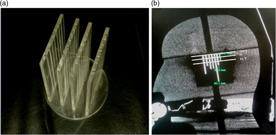
Figure 1. (a) Mini CT phantom and (b) acquired CT imaging response.
Central diode test tool
The GKPFX comprises a central radiation unit and a synchronised PPS. The radiation unit consists of 192 Co-60 sources arranged in a conical array inside source housing. All 192 radiation beam channels are focused to a single point, called radiological focus point. The focal point accuracy of the GK is defined as the congruence of the beam intersection point and the calibration point of the PPS. A simple method to relate machine tolerance at the dose delivery point is the determination of dose maximum (d max) point along three major axes. Twenty runs of the central diode test tool were evaluated to electronically quantify the SE (SEdiode test tool) in the localisation of the unit centre point.
Experimental plan preparation: a single-shot treatment plan
For treatment, the phantom’s head position was confirmed with the recorded reference position datasheet. Similar positioning to the reference head position or with reasonable positional deviation from the reference position reduces major treatment uncertainties in repeated-session treatment regimens. The comprehensive positional variation before treatment, if present, is calculated as the geometrical deviation and characterised by the radial difference vector (Δd) using Equation (2).
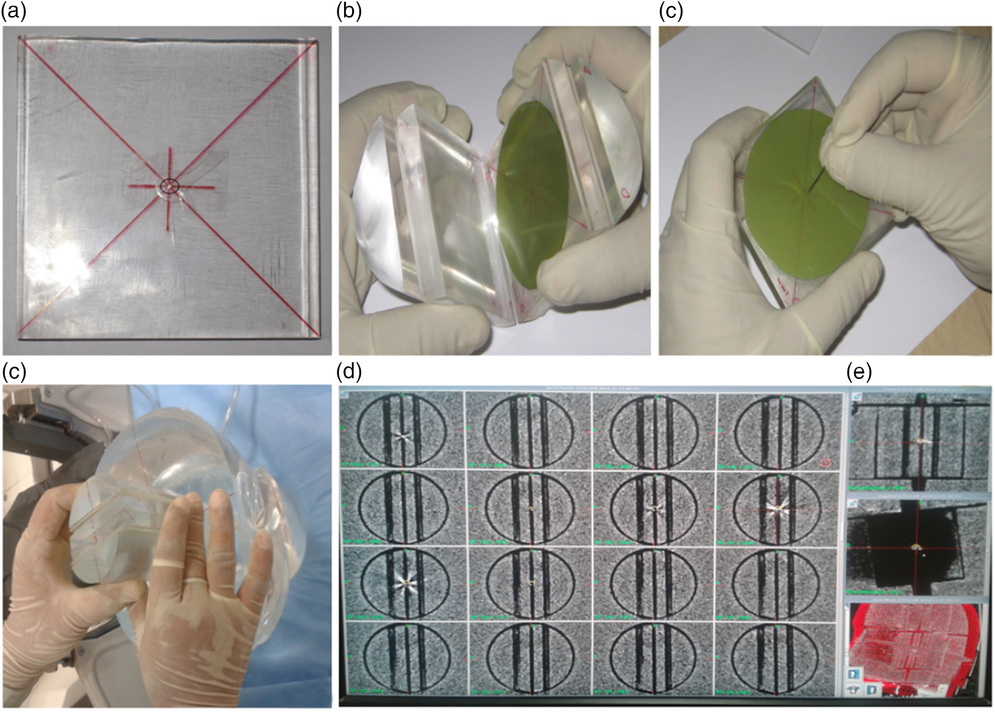
Two sets of stereotactic CT imaging sequences of the head–neck phantom at the treatment position were taken with an indigenously designed film adaptor. In the first set, the adaptor was kept in the coronal orientation, whereas in the second set the adaptor was rotated by 90 degrees to trace the sagittal planning plane (Figures 2a–2e). The centre of the adaptor was marked with a metal dot marker (Figure 2a). The CT imaging sequences in both orientations were fused together to ensure the congruence of the metal dot marker in the central plane. A single-shot plan with a 4 mm collimator and the isocentre on the metal dot marker, localised as (100·5, 101·7, 103·1), was created to deliver a radiation dose of 5 Gy, prescribed at the 50% isodose line. Four films were exposed at the localised point: two films represent the X–Z plane as their surfaces were kept perpendicular to the symmetry axis of source distribution, and the other two films placed perpendicular (Y–Z plane) to the first film group (Figure 2b). The films were marked for orientation at the periphery and centre with pinpricks as a mechanical means to determine the resultant radial positioning variation using the ES (Figure 2c). This experiment resembles a routine focal precision test and supports small field treatment accuracy with the ES (Figures 2d and 2e).

Figure 2. (a) Metal dot marker in the central plane, (b) film positioning with orientation marking, (c) central pin prick on the film for mechanical mean, (d) film adaptor positioning in dosimetric space of the phantom and (e) CT imaging response with metal dot marker.
Film dosimetry
Gafchromic EBT3 dosimetry films (International Specialty Products, Wayne, New Jersey, USA) were used for radiological verification of the experimental single-shot plan. The symmetrical structure of the film eliminates the need for tracking film surface placement on the scanner bed. The yellow colour dye on EBT3 film enables the benefit of multichannel dosimetry. The EBT3 films were scanned on a flatbed colour image EPSON scanner (Expression 10000XL; Epson America, Inc., Long Beach, California, USA). The films were scanned with 350 dpi at 48-bit colour depth after 24 hours of exposure and imported in the red channel. The radiological tests were performed using circular films of 6·5 mm diameter. The standard dosimetric procedure was followed and implemented for film detailing.Reference Sayer, Sherman, Yen, Schlesinger, Kersh and Sheehan 27 – Reference Hartmann, Martisiková and Jäkel 30
Statistical evaluation of the treatment
In mathematical computations, the result accounts for a specific range of values within which a true value is expected to fall. The most common way to show the measurement result is:
 $${\rm{Measurement = best \,estimate }}\left( {{\rm{mean \,value}}} \right) \pm {\rm{uncertainty}}{\rm{.}}$$
(5)
$${\rm{Measurement = best \,estimate }}\left( {{\rm{mean \,value}}} \right) \pm {\rm{uncertainty}}{\rm{.}}$$
(5)
An estimation of uncertainty is obvious in the investigation of radiological precision, where multiple measurements require judgment on the part of an experiment or procedure. The level of confidence in data collected quantifies the degree of accuracy of the procedure. An estimation of uncertainty in the ES for routine procedure is owing to imaging, measurements and/or GK precision. The treatment accuracy in view of the ES is modified as:
 $$T\,{\rm{ = }}\,\delta \pm U{\rm{,}}$$
(6)
$$T\,{\rm{ = }}\,\delta \pm U{\rm{,}}$$
(6)
where U = k * uc and uc = √(SE2 RCT + SE2 digital probe + SE2 imaging + SE2 diode tool), T is the mathematical treatment accuracy (measured), δ is an average positional shift for similar treatment settings (Σn=20 Δd/n) and U is an expanded uncertainty. uc is the combined uncertainty and the k factor = 1·96 for 95% of confidence level.
Results
In order to quantify the margin of error, the performance of tools associated with the treatment using the ES was evaluated under achievable routine treatment settings. The uncertainty caused by measurement tools affects the predication of treatment accuracy measures (T).
RCT and digital probe
On comparing measured RCT aperture values with indicative values (recorded during calibration), SERCT of 0·0186 mm (mean = −0·0100 mm; σ = 0·0373 mm) was observed. The aperture depths on the QA tool were measured using a small digital display probe. Twenty repeated measurements, following the S0-S1-S0 protocol for the digital probe, showed an SEdigital probe of 0·0002 mm (mean = 0·0035 mm; σ = 0·0005 mm).
Accuracy in radiological isocentre and diode test tool
An achievable radiological isocentre precision with diode test tool quantifies the geometrical accuracy between the treatment unit and the PPS of GK. Twenty runs under the predefined physics protocol for the diode test tool, planned and delivered at the unit centre point (100, 100, 100), ϒ = 90°, resulted in an SEdiode tool of 0·0096 mm (mean = −0·0820 mm; σ = 0·0430 mm) with a 4-mm collimator.
Imaging error
The distance between the dots on axial and coronal MR sequences was measured in the X–Y and X–Z LGP planes (Table 1). A standard deviation of 12 horizontal variations at intended geometrical separations of 96, 128 and 160 mm was observed as σ MR,axial = 0·1378 (mean = −0·1983 mm); and for six vertical variations of geometric separation of 20 and 80 mm, it was observed as σ MR,coronal = 0·1779 mm (mean = 0·0269 mm). Following Equation (3), SEMR was calculated as 0·0828 mm. Mini CT phantom studies for distortions in acquiring axial and reconstructed coronal/sagittal planes showed a σ CT,axial of 0·0957 (mean = 0·0250 mm) for four observations and a σ MR,coronal of 0·1282 mm (mean = 0·0250 mm) for eight observations (Table 2). The results of the CT studies were used to obtain an SECT of 0·0659 mm. Imaging uncertainty was calculated in the axial and coronal planes of the CT and MR sequences. SEimaging was calculated as 0·1055 mm using Equation (4).
Table 1. Distance between the dots on MR imaging, MR distortion phantom study
Table 2. Metal marker separation in mini CT phantom for linear distortion

Positional verification
Twenty treatment position settings of the head–neck phantom exhibited an average positional shift (δ) of 0·2752 mm (σ = 0·0696 mm; max 0·3600 mm) from the reference treatment position, whereas a minimum shift of 0·16 mm was practically achievable. An average positional shift (δ) of 0·27 mm was assumed as the treatment position shift in routine fSRS treatments. Post-treatment RCT measurements for all treatment position settings showed an average intra-fraction variation of 0·12 mm (range = 0·10–0·13 mm). The maximum variation in aperture depth measurement was observed in the anterior (max 1·0 mm, average 0·308 mm, SD 0·295 mm, SE 0·104 mm) followed by the superior (max 0·7 mm, average 0·259 mm, SD 0·274, SE 0·086 mm) RCT panel measurements.
Single-shot treatment: radiological precision
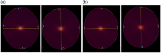
A few attempts were made before we could achieve a minimal treatment positional shift of 0·16, 0·17, 0·17 and 0·17 mm, for the coronal and sagittal film exposures. Figures 3a and 3b display EBT3 film irradiation in coronal and sagittal planes. Figures 4a–4d represent the X-axis, Y-axis and Z-axis density profile measurements for films as shown in Figures 3a and 3b. The density profile asymmetry, measured approximately at full width half maximum, demonstrates the distance between the radiological centre and the needle mark along the three major axes, calculated as δ 1 = 0·4650 mm and δ 2 = 0·4270 mm for two independent experiments (Table 3). In these experiments, we assumed that isocentre verification is the end-to-end radiological precision of the treatment, and therefore the results of the density profile asymmetry on the films are inclusive of the positional shift of ~0·17 mm, which is an average positional variation from the reference treatment position for the head–thorax phantom.
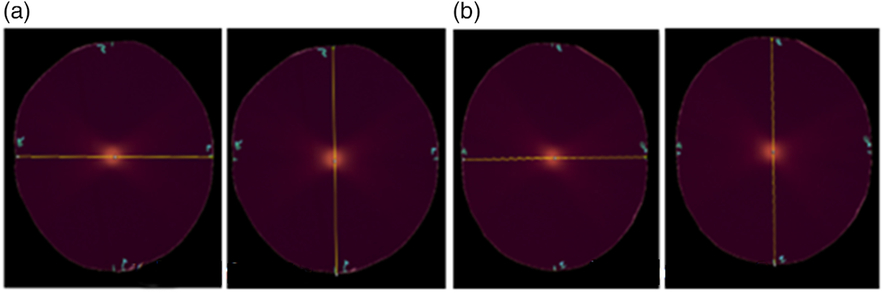
Figure 3. The response of EBT3 films when exposed in head–neck phantom; radiological isocentre precision check with a single 4-mm collimator shot plan for two independent experiments (a) and (b). (a) Experiment 1 and (b) Experiment 2.

Figure 4. (a,b) Density profiles in X-axis and Y-axis and (c,d) density profiles in coronal and sagittal planes using EBT3 films for experiment 1.
Table 3. Calculation of δ with head–neck phantom, where δx, δy and δz are positional shifts along the x, y and z axes, δ1 and δ2 are combined positional shifts along three major axes obtained from film set 1 and film set 2

Results of statistical evaluation of the treatment
The uncertainties at various levels of measurements and evaluations need to be included along with an average positional shift across fractions. The planned isocentre shift on the film is indeed inclusive of shared uncertainties (Table 4) caused by measurements, imaging and tolerance of the treatment machine.
Table 4. Statistical evaluation of uncertainties, where n is the number of measurements, σ is standard deviation and SE is the standard error
Using Equation (6), the combined uncertainty (uc ) was evaluated as 0·1210 mm. For higher and lower confidence levels of 95%, the best expression for the radiological treatment accuracy with our system is:
 $$T\,{\rm{ = }}\,\delta \pm U\,{\rm{ = 0}}{\rm{.27}} \pm {\rm{0}}{\rm{.23 \,mm}}$$
(7)
$$T\,{\rm{ = }}\,\delta \pm U\,{\rm{ = 0}}{\rm{.27}} \pm {\rm{0}}{\rm{.23 \,mm}}$$
(7)
using k = 1·96 for the normal distribution at 95% confidence level.
In this study, the calculation of expanded uncertainty resulted in the best estimation of treatment quality. A part of the measurement certifies that the experimental strength in estimating patient treatment with calibrated tools is decisive for meeting tolerances at various levels. The results of radiological precision (δ 1) of 0·4650 mm, (δ 2) of 0·4270 mm (experiments 1 and 2; Figure 3 and Table 3) with a single-shot exposure represent the radiological accuracy in patient treatment for small tumours as well; however, the value is arbitrary and unknown in real patient treatment. The present study aids in estimating factual radiological treatment accuracy with readily available positional shifts in clinics. A combined result of an average positional shift across fractions and expanded uncertainty with associated tools could demonstrate factual treatment accuracy of 0·27 ± 0·23 mm. The value marginally varies (maximum: from −0·03 to +0·04 mm) from the experimental results of the radiological precision check with a single-shot experimental plan.
Discussion
The ES of GKPFX is designed to assist with the accurate delivery of a radiation dose in multiple lower-dose fractions to the target volume in the brain.Reference Ma, Pinnaduwage, McDermotte and Sneed 23 , Reference Ruschin, Nayebi and Carlsson 26 , Reference Sayer, Sherman, Yen, Schlesinger, Kersh and Sheehan 27 , Reference Kim, Sheehan and Schlesinger 31 – Reference Bisht, Kale and Natanasabapathi 34 The ES provides good repositioning accuracy and adequate immobilisation to the patient’s head during fractionated treatments.Reference Ruschin, Nayebi and Carlsson 26 , Reference Sayer, Sherman, Yen, Schlesinger, Kersh and Sheehan 27, Reference Kim, Sheehan and Schlesinger 31 , Reference Schlesinger, Xu, Taylor, Yen and Sheehan 33 Various studies reported that the inter-fraction and intra-fraction positional variation with the ES is comparable with other fractionated techniques such as image-guided radiosurgery.Reference Kim, Sheehan and Schlesinger 31 , Reference Schlesinger, Xu, Taylor, Yen and Sheehan 33 Following this work, Ma et al. suggested modified Winston-Lutz test to determine the device accuracy for a repeated-session treatment.Reference Ma, Pinnaduwage, McDermotte and Sneed 23 Bisht et al. compared all fractions using Gafchromic EBT3 films and demonstrated the efficacy of ES following hypofractionated regimen.Reference Bisht, Kale and Natanasabapathi 34
This study was performed to evaluate ‘technical treatment accuracy’ within ‘known uncertainties’ associated with the ES in routine fSRS procedures. The phantom study allowed the measurement of 39 RCT apertures to record the reference treatment position, which is unusual in actual patient treatment setups. However, recording of the maximum possible RCT apertures during patient positioning improves the overall positional accuracy of the treatment. The smooth curvatures of the phantom/patient’s skull opposing the superior and anterior panel might significantly influence the estimation of patient position with RCT measurements.
The uncertainty at various levels of measurement causes misleading results in the estimation of the margin of treatment error. Calibration of the RCT is recommended, when there is any suspected damage or change in shape. Similarly, ‘setting the correct zero’ position of the digital probe is required to be performed when a new probe is used or the battery/probe tip is replaced. In this study, the SE of measurement tools was minimal, though the value was incorporated in optimised uncertainty calculations. The SEdiode tool was evaluated to represent the tolerance of the GK machine. The tumour definition with CT depends on the image resolution or consequently the voxel dimension. 22 A routine imaging protocol for SRS patients with a pixel spacing of 0·5 × 0·5 mm and a slice thickness of 1·0 mm was chosen for the present imaging studies. The primary study was done using an in-house-developed CT phantom, which needs subtle improvisation to be used as a standard QA tool, though the metal bar measurements of the CT phantom in the axial and reconstructed coronal planes were used for introductory estimation of SE. The SEimaging for CT and MR was decisive for evaluating the combined and expanded optimal uncertainty, which need to be elaborated upon in future uncertainty studies.
Patient surveillance unit
The head and neck movement of the patient is regulated by a vacuum-supported stable dental mould in the ES. A suction level drop ≥10% from the baseline puts the patient treatment on hold temporarily. In this case, the system requires repositioning of the patient before proceeding with the treatment. The positional variation in suction drop ranging between 0 and 10% might result in patient movement, but within treatment tolerance. A suction of 40% remained uninterrupted for the phantom studies, which nullified the chances of phantom repositioning during treatments. The patient treatment with these events may cause additional uncertainties and needed to be incorporated for statistical concerns.
The treatment uncertainty determination with a single-shot or radiological precision experiment is simple and is the first step towards an estimation of factual treatment accuracy in routine fSRS. In the case of multiple, dynamic and complex shots, the calculations with additional uncertainties might be more complicated. In the present study, an average positional shift was used to evaluate treatment accuracy in routine clinic treatment. However, future in vivo studies performed for consecutive days could possibly evaluate definite uncertainties in treatment or act as a complete verification tool. The study may be extended in the future to quantify clinical uncertainty due to target and OAR delineation, which may predict imaging resolution concerns. The guidelines for tumour margins of specific or small targets to be treated with higher cumulative radiation dose need to be evaluated specifically for complex tumours.
Conclusions
The phantom study indicates that the ES with GKPFX can be used to deliver fractionated radiosurgery with sub-millimetric accuracy for the treatment of small target volumes. In order to obtain the radiobiological advantage of fractionation, small critical targets require clinical acceptance before selection following hypofractionated regimens. Quality assurance of tools like the RCT, digital probe and vacuum-assisted head cushion integrity is essential for reliable patient positioning using the ES. The selection of suitable RCT apertures for determining the reference treatment position minimises the positional uncertainty in fractionated treatment. The surrogacy of a dental mouthpiece and its mutual compliance with PSU may lead to unknown suction-level-related concerns. Hence, special care should be taken in the selection and measurement of superior and anterior RCT apertures. The present study predicts the technical treatment uncertainty in the clinic, whereas combining the results with explicit medical uncertainties such as having knowledge of neurological abnormality and radiation response will be in the scope of future research in treatment accuracy determination.
Acknowledgements
A part of this study was accepted for presentation in 14th AOCMP/SEACMP 2014, Ho-Chi-Minh City, Vietnam, organised during 23–25 October 2014 (P-086). A part of study was accepted for e-poster presentation in the International Leksell Gamma Knife Society Meeting, 2016, Amsterdam, The Netherlands, organised during 15–19 May 2016 (A-723-0000-00057). The study has been accepted for the presentation in the 58th annual meeting and exhibition of the AAPM in Washington, DC, organised during 31 July–4 August 2016 (SU-F-T-595).
Source of support
The study was financially supported by the All India Institute of Medical Sciences, New Delhi, India, through an intramural research project no. A -247.
Conflict of interest
The authors declare that they have no conflict of interest.