


Introduction
Intensity-Modulated Radiation Therapy (IMRT) is a further refinement of the segmented beam technique in which each of the treatment fields is made up of many segments. IMRT optimally assigns non-uniform intensities (i.e., weights) to tiny subdivisions of beams, which have been called rays or ‘beamlets’. The objective is to produce higher conformity than is achievable with conformal blocked fields. In IMRT each radiation beam is divided into many subfields.Reference Jabbari, Amouheidari and Babazadeh1 The ability to optimally manipulate the intensities of individual rays within each beam permits greatly increased control over the radiation fluence, enabling the custom design of optimum dose distributions.Reference Ma, Mok and Kapur2 These improved dose distributions potentially may lead to improved tumour control and reduced normal tissue toxicity.Reference Al-Rahbi, Al Mandhari and Ravichandran3–Reference Xia and Verhey11
In advanced delivery techniques, such as intensity-modulated radiotherapy (IMRT) and volumetric-modulated arc therapy, the multi-leaf collimators (MLCs) are employed to dynamically shape the beam during the deliveryReference Galvin, Chen and Smith12–Reference LoSasso, Chui and Ling16 to achieve highly conformal dose distributions.
By delivering typically five to seven beams with an individualised intensity profile, the dose is conformed to the volume and normal tissue and critical organs spared.Reference Van Esch, Huyskens and Behrens17 The individual treatment beams for IMRT can be delivered using MLCs in either dynamic or multiple-segment (‘step and shoot’) mode. The complexity of IMRT plans may originate from the design of inverse planning systems, typically using pixel-based or fluence-based optimisation. In general, this type of optimisation first divides a broad beam into many small beamlets (e.g., 1 cm × 1 cm), and then the intensities of these beamlets are adjusted according to the planning dose objectives to minimise the value of an objective function.Reference Ling, Burman and Chui18 Finally, the optimised intensity patterns are decomposed into a series of deliverable MLC shapes (segments) each associated with a uniform dose. This decomposition step is referred to as leaf sequencing. The entire process is known as two-step optimisation.Reference Mohan, Arnfield, Tong, Wu and Siebers19–Reference Chen, Xing and Nath21
Among various issues related to verifying the treatment, a pressing problem is how to verify efficiently the calculation of monitor units (MU) from a commercial inverse planning system. An independent MU check is required for patients treated through complex techniques such as IMRT, IGRT, etc.Reference Georg, Garibaldi and Dutreix22 It is standard practice in external beam radiotherapy (EBRT) to verify independently the calculation of MU before the start of patient treatment. For intensity-modulated radiotherapy, an independent calculation of MU becomes difficult due to the complex relationship between the MU and the beam-intensity modulation shape as well as the technique used to generate the intensity modulation.Reference Xing, Chen, Luxton, Li and Boyer23 Several authors experimented with methods to verify monitor unit checks through analytical calculations. The MU calculation for a multi-leaf collimated static field has been described in the literature.Reference Williams24 A few attempts have been made to develop more efficient techniques for the verification of dynamic delivery. Boyer et al. have investigated some theoretical aspects of the MU calculation for an intensity-modulated field.Reference Wang, Spirou, LoSasso, Stein, Chui and Mohan25
The control points (CP) play a significant role in the delivery of segmented based IMRT delivery, particularly in dynamic mode.Reference Xing, Curran, Hill, Holmes, Ma, Forster and Boyer26 The dynamic delivery sequence is approximated with multiple segments or subfields that deliver a fixed number of monitor units for specific leaf positions, collimator angle and gantry angle called as control points. These segments will transfer from one to the other either during beam ON called as dynamic delivery or during beam OFF called as static delivery or step and shoot. A dynamic delivery IMRT field file will contain several control points at a marked fraction of the delivered monitor units, which are specified as MLC shapes. Deliverable fluence fidelity is proportional to the number of control points defined.
The present study is aimed to exploit the features of control points and estimate an indirect approach for estimating the monitor units per segment in a dynamic IMRT delivery.
Materials and Methods
This study was performed in the Eclipse treatment planning system (TPS) version 13.8.0. (Make: Varian Medical Systems, Palo Alto, USA). The treatment plans of patients who received Intensity-modulated Radiotherapy were selected for this study. A total of 30 patient’s plans were randomly selected with 10 each for the head and neck region, cranium and cervix for monitor unit verification calculation (MUVC). The IMRT plans were optimised by the Photon Optimizer algorithm and the calculated fluence was delivered through MLC. The movements of MLCs were calculated by the leaf motion calculator. Dose calculation was performed by an Anisotropic and Analytical algorithm with a spatial resolution of 0·25 cm.
The Linear accelerator in which this study performed was Clinac 2300CD, (Make Varian Medical Systems, Palo Alto, USA) which can deliver dynamic and static IMRT with 40 pairs of MLC. The dynamic delivery was approached with more ‘segments’ or ‘subfields’ each will deliver a fixed number of monitor units. These segments had different aperture shape according to the fluence required to deliver in that particular phase. The calculated fluence was delivered with the gantry and collimators fixed. The segments were delivered dynamically, that is, the transition from one segment to the other while beam ON and the same were converted into control points to execute the IMRT delivery in the linear accelerator machine. Each control point defined had specific leaf positions of bank A and bank B that form the aperture by which the MUs were delivered. The control points were assigned metre set weight according to the field size and dose to be delivered through that field. The first control point always had a value of zero with variable parameters gantry, collimator angle, and field size of the first segment. The second control points have the cumulative MU of the first segment but with the aperture of the first segment. The transition from the second to the third segment delivered the MU of the first segment. Thus the complete segmented based dynamic IMRT was delivered.
In our study, we attempted to estimate the total monitor units to be delivered per field by exploiting the control points of a specific field. This would give an indirect method to estimate the MU per field and the total MU for the complete treatment can be estimated. The MLC properties will have the details of control points, metre set weight per segment, leaf positions for each segment, field size, etc. Additionally, it will provide the information of the total MU for the particular field at the end of the control point. The IMRT plans were transferred to the I’MatriXX phantom as similar to fluence verification for patient-specific QA, Figure 1.
(i) Estimation of monitor unit per segment:

Figure 1. IMRT fluence delivered in phantom and respective control points.
The total MU calculated depends on the field area to be covered, dose prescribed at the depth of the patient, and the number of beams used in the plan. The control points also an important parameter for MU delivery. We derived a conceptual equation for estimating the MU delivered for each segment.
 $${\bf MU}_{\bf seg} = {{\bf MU_{cal}} \over {\bf{\Sigma} \,{\bf{no}}\,{\bf{of}}\,{\bf{control}}\,{\bf{points}}}}$$
where
MU cal = Total MU calculated by the TPS
MU seg = MU per segment
C.P = control points of the field
This equation depicts that the control point plays a vital role in the delivery of MU for the IMRT fields. The number of control points was taken from the MLC plan properties for each field. The calculated MU per segment from the above-mentioned formula was to estimate the total MU required to deliver the total MU for the field. The calculated total MU by the newly developed method was compared with the TPS calculated MU and comparisons were made between the two methods.
-
(ii) Estimation of MU delivered up to n th control point:
The MU per segment was considered as a modulation factor that determines the MU for any control point. The total MU delivered up to n th can be found at any of the in-between control points by summing up the metre weight up to the n th control point.
 $${\bf MU}_{\bf c.p} = {\bf MU}_{\bf seg} \times {\bf \Sigma} {\bf CP}_{\bf\it i}$$
where
MU C.P = Monitor unit delivered up to n th control point
MU seg = MU per segment
ΣCP i = i th control point
Through Equation (1) MU per segment was calculated and total MU for any field was estimated. The treatment plan of seven field techniques was taken for the study. Equal field weight was given for all the seven fields. The MU estimated through Equation (1) was compared with the TPS calculated MU and the comparison was made between the proposed analytical method and the TPS calculated method.
The total MU that would be delivered for any in-between segments can be estimated by building the relationship between the control point and the MU per segment. The relationship will be mostly of linear equations y = ax + b, where y = MU per segment, x = control point.
 $${\bf{MU}}\,{\bf{for}}\,{{\bf\it{n}}^{{\bf{th}}}}\,{\bf{control}}\,{\bf{point}} = {\bf{MU}}\,{\bf{per}}\,{\bf{segment}} \times {{\bf\it{n}}^{{\bf{th}}}}\,{\bf{control}}\,{\bf{point}} + {\bf{intercept}}\,{\bf{(zero}}\,{\bf{control}}\,{\bf{point)}}$$
-
(iii) Verification by measurements:
The method of total MU estimation was verified by the dosimetry performed through the point dosimetry method and also with I’MatriXX detector array (Make: Scanditronix Wellhofer). The plans were transferred to the I’MatriXX scanned phantom and tissue-equivalent phantom in Eclipse TPS as a routine method of plan verification. All the fields were placed in gantry zero position and dose calculation was performed again. The procedure previously outlined for the estimation of total MU for each section were performed. Dose calculated plans were transferred through the record and verify mode to the control computer. The externally calculated MU were delivered through the service mode of this Linac to compare the dose delivered to the calculated dose by the TPS.
The MLC files were exported from the TPS and the same files were reproduced in the MLC shaper software. The shaper software was used to regenerate the MLC leaf positions for each segment. These reinforced MLC leaf positions were transferred to the control console of Linac. By doing so we had the independency of delivering the desired MU for any segments.
The calculated MU by the above-mentioned methods was delivered and the dose at the reference point was estimated. The usage of I’MatriXX helped not only for estimating the dose delivered at the isocenter but also the overall fluence in the plane estimation.
The dose estimated by the I’MatriXX system and the dose calculated by the TPS were both compared (Figure 3, Table 4)
-
(iv) Estimation of MU delivered up to n th control point:
The fields identified for finding the linear relationship between MU per segment and control points are shown in Table 2.
Results
A total of 30 cases were taken for evaluation from the head and neck region, cranium, and cervical cancers respectively as described in Table 1. As mentioned in the formula….1 MU per segment was estimated from the inputs, total MU for the field, and the total number of control points. Through the analytical method, we estimated the total number of monitor units required with the help of the total number of control points and MU per segment.
Table 1. Treatment sites have taken for MUVC verification

A comparison was made between the TPS calculated MU value and analytically estimated MU. Fields namely anteroposterior (AP), left anterior oblique (LAO), left lateral (LL), and left posterior oblique (LPO) taken for evaluation Table 2. The comparison of these two methods of estimation is described in Figure 2 and Table 3.
Table 2. Fields have taken for finding relationships between the control point and monitor unit


Figure 2. Comparison between TPS calculated MU and analytically estimated MU.

Figure 3. Comparison between TPS calculated dose and measured dose at I'MatriXX.
Table 3. Control point and comparison of MU between analytical method and TPS

Table 4. Comparison of measured dose and calculated dose between I’MatriXX and TPS
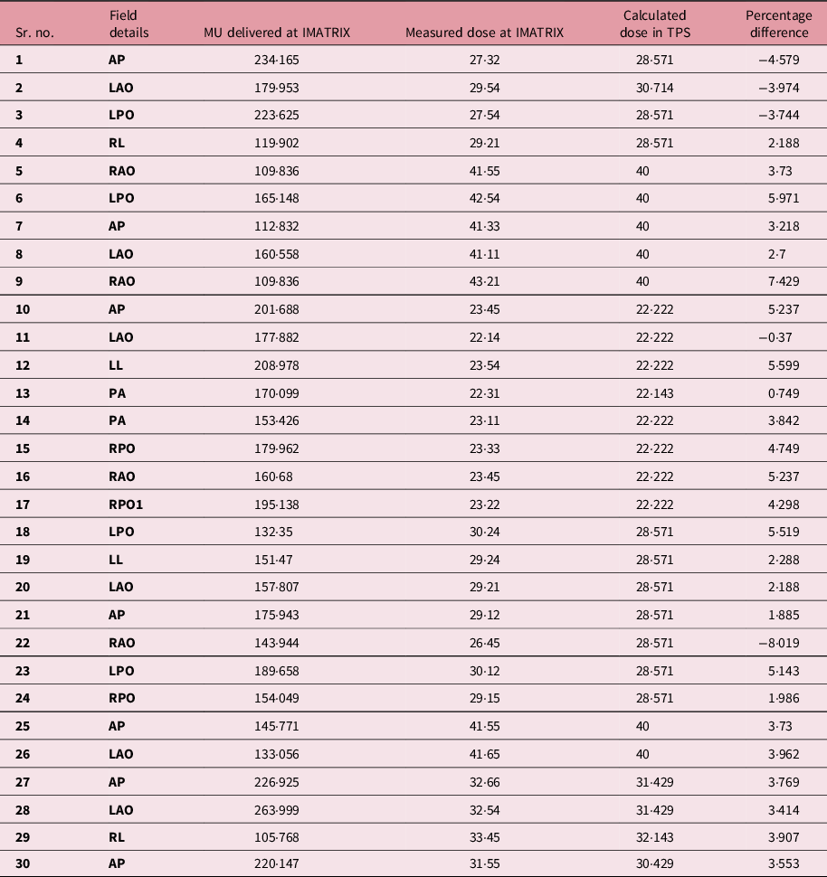
Table 5. Statistical significance

The percentage of deviation between TPS calculated MU and analytically estimated MU was also determined. The mean percentage of deviation was 1·03 and p-value <0·05, Table 5. The overall mean percentage of deviation was 1·03% between the TPS calculated method and the analytical method. The paired sample t-test was performed and, p-value <0·05, no significant difference was found.
Discussion
The intensity modulation of radiation delivery has had a positive impact on the delivery of treatment using radiotherapy and has greatly expanded the opportunities of the specialty. IMRT being a potential and robust technique in delivering the desired fluence according to the tumour shape and size by reducing the dose to nearby normal structures. Even though IMRT can be delivered by various delivery methods it can be potentially delivered in a simplified way with the MLC. The most common IMRT delivery requires the use of moving MLCs to deliver the requested fluence pattern. Reference Wang, Spirou, LoSasso, Stein, Chui and Mohan25 In dynamic IMRT, the required pattern of dose distributions is delivered through the small segments. Reference Xing, Curran, Hill, Holmes, Ma, Forster and Boyer26,Reference Ludlum and Akazawa27
The relationship between the MU and control points were studied for five cases as mentioned in Figures 4 and 5. The parameters namely the number of control points, TPS calculated MUs were taken for analytical MU estimation. The relationship between MU and control points has shown that the MUs have a highly linear relationship with the control points. The correlation co-efficient resulting in near to unity proves the fact. With this relationship, we can estimate the total number of MU delivered for any n th control point. The MUs for any n th control point can be estimated with the help of formula… (2). Through this study, an attempt was made to estimate the monitor units delivered per control points. We have explored the control point’s functionality and the monitor unit per segment was estimated.

Figure 4: Relationship between the control point and monitor unit. (a) Relationship between CP and MU for MU/segment 1·339 and total control points 139. (b) Relationship between CP and MU for MU/segment 1·159 and total control points 201.

Figure 5. Relationship between the control point and monitor unit. (a) Relationship between CP and MU for MU/segment 1·064 and total control points 203. (b) Relationship between CP and MU for MU/segment 0·773 and total control points 190.
For complex head and neck cases, as many as 130–160 segments with 9 beam angles are needed. 28 Studies have been performed by various authors concerning an attempt to reduce the number of segments in IMRT delivery. The reduction of radiation efficiency is not only due to the use of many segments but also due to the dramatic increase in the number of monitor units (MUs). Reference Galvin, Ezzell and Eisbrauch29 The increase in the number of MUs leads to leakage and head scatter and can affect the accuracy of treatment delivery. Reference Mohan, Arnfield, Tong, Wu and Siebers19 More importantly, the increased exposure from complex IMRT plans may also increase the frequency of radiation-induced secondary malignancies. It has been recently reported that the transition from 3D conformal radiation therapy to IMRT resulted in a larger volume of normal tissue exposed to a low dose of radiation, which was estimated to increase the incidence of secondary cancers at 10 years from 1 to 1·75%. Reference Hall and Wuu30
In our study, we have observed that the most of the segments were more than 100 in number, Figure 6, and attempts may be made to reduce the control points to reduce the MU for patient delivery.
The average numbers of control points were 151·43 ± 43. This indicates that the control points were in a significant number for every field. For 30 clinical cases and using formula 1, the mean MU per segment was 1·13 ± 0·214. Through this, it is understood that the minimum MU per segment will not be less than unity and hence the number of segments will lead to more number of MU for any IMRT delivery.
Some studies have been published in the domain of control points/segments. Some special algorithms reduce the total number of segments, while others minimise the total required MU. Reference Hansen, Bucci, Quivey, Weinberg and Xia31–Reference Siebers, Lauterbach, Keall and Mohan35 Other researchers have proposed the use of smoothing filters to eliminate unnecessary noise inside the intensity profiles, either during optimisation or before leaf sequencing. Reference Siebers, Lauterbach, Keall and Mohan35–Reference Crooks, McAven, Robinson and Xing37
To simplify IMRT plans while improving delivery and radiation efficiency, many researchers have been working on increasing the efficiency of leaf sequencers. Reference Kamath, Sahni, Li, Palta and Ranka34,Reference Bednarz, Michalski, Houser, Huq, Xiao, Anne and Galvin38,Reference Spirou, Fournier-Bidoz, Yang, Chui and Ling39 Some leaf sequencers minimise the total number of segments, while others minimise the total required MUs. Reference Sun and Xia36,Reference Coselmon, Moran, Radawski and Fraass40 With most commercial planning systems, options for controlling the complexity of an IMRT plan are often limited to choosing coarse intensity levels during conversion, selecting a leaf sequencer that can provide an optimal delivery efficiency for the specific delivery method (e.g., sliding window or step and shoot) or utilising smoothing filters. Reference Keller-Reichenbecher, Bortfeld, Levegrün, Stein, Preiser and Schlegel41–43 However, the effectiveness of these methods in controlling the complexity of an IMRT plan is limited, often resulting in significant deteriorations in plan quality.
Conclusion
The control points are a potential parameter in the conventional IMRT delivery. Through this study, we have addressed the indirect method to estimate the monitor units delivered per segment with the TPS MU input. The average number of segments per IMRT treatment delivery and average MU per field were also estimated with the limits of 30 number of fields. The extension of this study can be performed as the methods to reduce the number of segments to achieve the same results without disturbing the plan quality in Eclipse TPS. Also, an analytical method can be found to estimate the MU per segment to be an independent method of MU calculation.


