


INTRODUCTION
External beam radiotherapy aims to enhance the therapeutic index by maximising the ratio of the probability of tumour control to the normal tissue complications. With the advent of high precision radiotherapy, like conformal radiotherapy, intensity modulated radiotherapy (IMRT) with image guidance (IGRT), it is feasible to reduce the margin given to the clinical target volume minimising the dose to normal structures. To achieve this objective, reduction of the geometric uncertainties associated with planning and treatment execution is important. Errors can be introduced during imaging, volume delineation and during positioning the patient.Reference Hurkmans, Remeijer, Lebesque and Mijnheer1–4 Setup errors, like systematic and random errors, cause failure to achieve desired dose to the target volume. Several authors have used systematic and random errors in deriving the CTV to PTV margin.Reference Stroom and Heijmen5–Reference Bel, van Herk and Lebesque7 When allowing a fixed reduction of the minimum cumulative dose (i.e. to 95%), the effect of the random error on margin is small (i.e. 0.7 σ) compared to the systematic error.Reference van Herk8 Many published margin recipes ignore systematic errors or fail to differentiate between systematic and random errors.
Immobilisation of the region of treatment is important in high precision radiotherapy. Alpha cradle and thermoplastic ray cast are two commonly used immobilisation devices for abdominopelvic radiotherapy. Any centre practicing high precision radiotherapy must follow strict quality assurance protocols. The analysis and quantification of the errors during treatment execution should be an integral part of quality assurance. This helps to derive patient- specific clinical target volume (CTV) margins based on the immobilisation device. The aims of the present work were (1) Comparison of Alpha Cradle (also called Vaclock, henceforth shortened as VL) and Thermoplastic Ray Cast (henceforth shorted as RC) as immobilisation devices in terms of setup errors and positional accuracy for abdominopelvic radiotherapy based on bony landmark matching using electronic portal imaging (EPI); (2) Quantification and comparison of total, systematic and random errors in mediolateral (ML), craniocaudal (CC) and anteroposterior (AP) directions; (3) To derive the CTV to planning target volume (PTV) margin based on the systematic and random error measurements.
MATERIALS AND METHODS
All participants were explained about the study and were included after they had signed the informed consent form. The study was approved by the Institutional Review Board. Twenty participants were randomised by block randomisation either to immobilisation with VL or thermoplastic RC (Figure 1). All patients had contrast-enhanced CT scan which was used for contouring the volumes of interest (Gross Tumour Volume or GTV, Clinical target Volume or CTV, Planning Target Volume or PTV, Organs at risk or OAR) as per International Commission of Radiation Units (ICRU)-50 and 62 guidelines.3 Planning was done using the Plato IRIX version 6.5 treatment planning system and 5 mm margin was given to the PTV while carrying out the treatment planning. Digitally reconstructed radiographs (DRR) were generated for referencing. Patients were treated on dual energy Primus Linear Accelerator (Siemens, USA) capable of delivering 6 and 15 MV photons and a range of electron energies and fitted with a Si-based EPID system (Siemens, Germany). The EPID had a sensitive area of 41 × 41 cmReference de Boer, van Sörnsen de Koste, Senan, Visser and Heijmen2 (pixel matrix size 512 × 512).
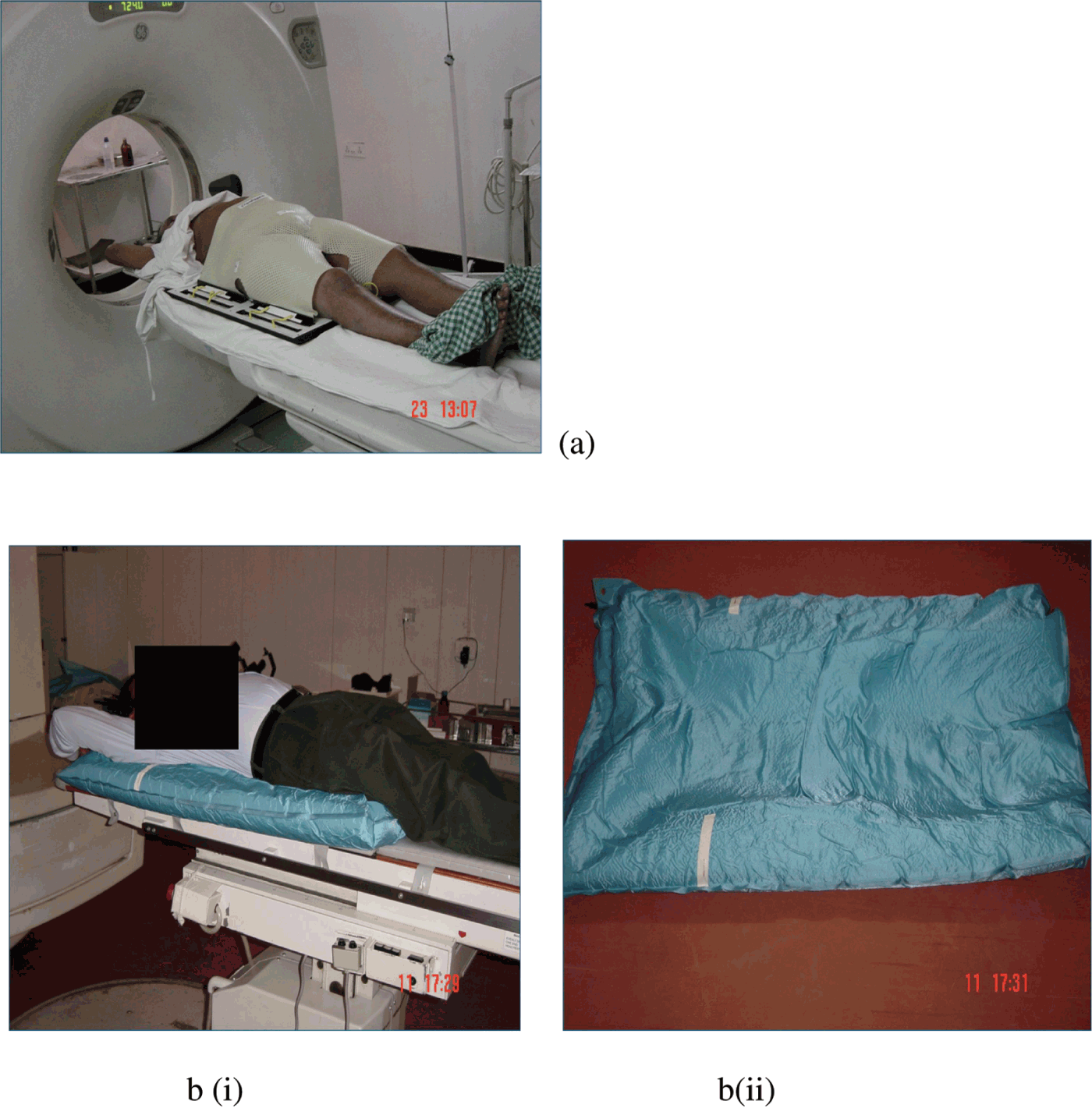
Figure 1. Immobilisation of patients with thermoplastic ray cast and alpha cradle.
During the course of radiotherapy treatment orthogonal (AP and lateral), double exposure EPI were acquired for set-up verification. These images were compared with the DRR in reference to several fixed bony points like, ischial spine, symphysis pubis and pelvic brim, etc. The EPIs were taken on first 3 days and once weekly, thereafter. If values were not acceptable and required online correction, imaging was continued till three acceptable values were obtained. The total errors in ML, CC and AP directions were measured.
Displacements were compiled and arithmetic mean was calculated (individual systematic error). Individual systematic error was subtracted from total error to obtain random error for each treatment episode. The standard deviation of individual systematic error gave the population systematic error (Σ) and standard deviation of individual random errors gave the population random error (σ,). The CTV to PTV margin was calculated using ICRU 62 (Σ + 0.7 σ) Stroom’s (2 Σ + 0.7 σ) and Van Herk’s (2.5 Σ + 0.7 σ) formula.Reference van Herk8 Statistical significance was calculated using t-test and variance ratio test (F-statistics). For statistical significance, p ≤ 0.05 was considered significant. For each immobilisation, average total error for all patients in ML, CC and AP directions were plotted against time to assess the time trend of displacement.
RESULTS
A total of 20 participants were randomised to two immobilisation devices with 10 in each group. The two groups were comparable in terms of age, sex, average number of treatment fractions and number of portal images analysed. This data is shown in Table 1. We compared the bony anatomy of the region of treatment with the DRR. Bony anatomy was used as a surrogate marker of the anatomic region treated. The bony anatomy compared involved pelvic region and spinal anatomy, and the number of pelvic and spinal anatomy analysed in each group were comparable among the groups. A total number of 306 portal images (153 lateral and 153 AP) were analysed with 144 images in RC group (72 anterior and 72 lateral) and 162 images (81 anterior and 81 lateral images) in VL group.
Table 1. Patient characteristics: VL group and RC group

All patients (VL and RC groups combined)
Translational shifts were measured in all 306 images. The mean displacements in ML, CC and AP directions were 0.11 cm (SD 0.58), 0.09 cm (SD 0.67) and 0.03 cm (SD 0.60), respectively. The systematic errors were 0.35 cm, 0.32 cm and 0.41 cm and random errors were 0.47 cm, 0.59 cm and 0.48 cm in ML, CC and AP directions. The PTV margins calculated by Stroom’s formula were 1.04 cm, 1.07 cm and 1.16 cm, respectively, in ML, CC and AP directions (Table 2). In 70 to 80% of the measurements, total translational error was within 5 mm (Table 3). The total errors in ML, CC and AP directions were normally distributed (Figure 2).
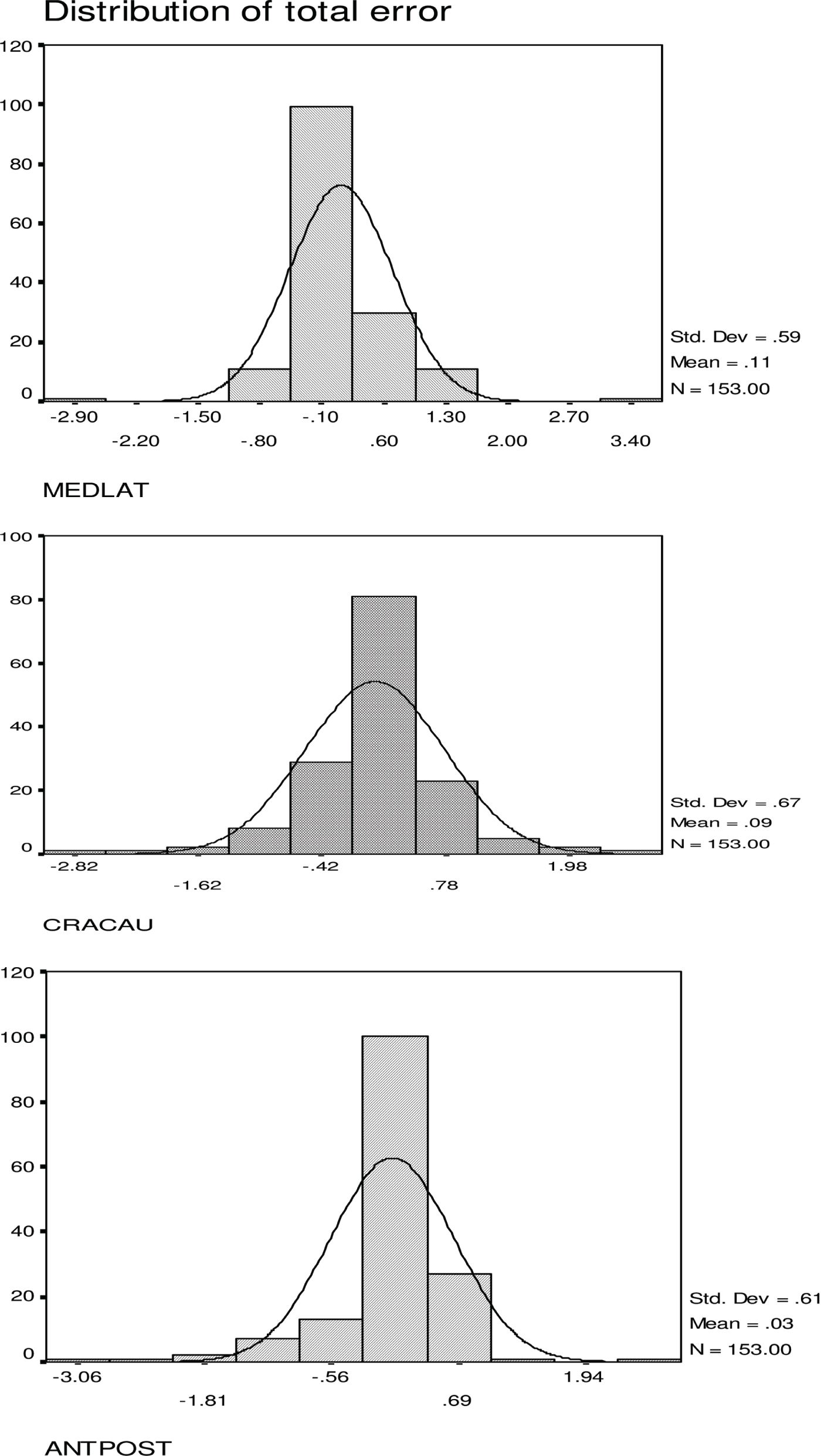
Figure 2. Distribution of total error in ML, CC and AP directions (immobilisation with VL and RC).
Table 2. Mean, standard deviation, systematic and random error, PTV margin using ICRU, Stroom’s and van Herk formula Immobilisation—Alpha cradle (VL) and ray cast (RC) in cm

Table 3. Distribution of error
Note: (Denominator is total number of EPIs analysed, VL = alpha cradle, RC = ray cast).
Alpha cradle immobilisation (VL group)
Mean total displacements in ML, CC and AP directions were 0.07 cm (SD 0.63), 0.15 cm (SD 0.40) and 0.006 cm (SD 0.708), respectively, and it was normally distributed. The systematic errors were 0.45 cm, 0.29 cm and 0.42 cm and random errors were 0.49 cm, 0.32 cm and 0.59 cm respectively, in ML, CC and AP directions. The PTV margins calculated by Stroom’s formula were 1.24 cm, 0.804 cm and 1.25 cm, respectively, in ML, CC and AP directions.
Immobilisation with thermoplastic ray cast (RC group)
Mean total displacements in ML, CC and AP directions were 0.16 cm (SD 0.53), 0.02 cm (SD 0.88) and 0.06 cm (SD 0.47), and it was normally distributed. The systematic errors were 0.25 cm, 0.37 cm and 0.42 cm and random errors were 0.46 cm, 0.80 cm and 0.34 cm respectively, in ML, CC and AP directions. The PTV margins calculated by Stroom’s formula were 0.82 cm, 1.3 cm and 1.08 cm, respectively, in ML, CC and AP directions.
PTV margin calculations in all patients and in different subgroups
The CTV to PTV margins were calculated using ICRU, Stroom’s and Van Herk’s formula. The CTV to PTV margins were 0.69 cm, 0.74 cm and 0.75 cm, respectively, in ML, CC and AP directions by ICRU formula. Margins calculated by Stroom’s formula were 1.04, 1.07 and 1.16 cm in ML, CC and AP directions and 1.22 cm, 1.24 cm and 1.36 cm, respectively, by Van Herk’s formula. The results show that largest margin is required in AP directions (Table 4). In ML direction, systematic error (0.25 cm versus 0.45 cm), random error (0.46 cm versus 0.48 cm) and CTV to PTV margin (0.82 cm versus 1.2 cm) were less for RC compared to VL but this difference was not statistically significant. In CC direction, total error was more in VL than RC (1.5 mm versus 0.15 mm, p = NS). However, VL had less systematic error (0.29 cm versus 0.37 cm, p = NS) and significantly less random error than RC (0.32 cm versus 0.80 cm, p < 0.05). The CTV to PTV margin was also significantly less in VL than RC in the CC direction (0.8 cm versus 1.3 cm, p = 0.03). In AP direction, total error was less with VL than RC (0.067 mm versus 0.61 mm). Systematic errors were almost same (4.1 mm versus 4.2 mm), but RC had less random error than VL (3.3 mm versus 5.8 mm, p = 0.03). The CTV to PTV margin calculated was less in RC than VL (1.08 cm versus 1.25 cm) though this difference was not statistically significant (Table 5).
Table 4. Shift CTV–PTV margin: VL and RC

Note: CTV–PTV margin: *ICRU (Σ + 0.7 × σ), **Stroom’s formula (2 × Σ + 0.7 × σ), ***van Herk’s formula (2.5 × Σ + 0.7 × σ).
Table 5. Comparison of total error, systematic error, random error and PTV margin (Stroom’s formula) between VL and RC

Time trend analysis
Average of total error every week in each direction for 20 patients was compared. This provided an idea of behaviour of total error across time and also was an indicator to the consistency of the immobilisation device over a period of time. Similar comparison between VL and thermoplastic RC showed the range of shift in VL to be (+0.75 to –0.25 cm), whereas for thermoplastic RC it was between ± 0.5 cm. The VL appeared to be a better immobilisation device than RC as per time trend analysis though in both cases the errors were within acceptable limits (Figure 3). All patients were monitored for radiation-induced reactions and weight changes weekly. There was no clinically significant change of body weight during the course of treatment.

Figure 3. Time trend analysis of total error in abdomen and pelvis. Upper panel: VL immobilisation; Lower panel: RC immobilisation.
DISCUSSION
A significant reduction in local disease control can result from even small (7–15%) changes in dose. The ICRU report recommends accuracy in dose delivery, which should be within ± 5%.Reference Sweeney, Bale and Vogele9An ideal immobilisation should not only immobilise the region of interest but should also be easy to set up and comfortable.Reference Saw, Yakoob, Enke, Lau and Ayyangar10 In treatment set up without immobilisation, the proportion of fractions with set-up errors greater than the 5 mm ranges from 17% to 57% and greater than 10 mm are observed in up to 15% of fractions.Reference Rosenthal, Roach and Goldsmith11 Several reports comparing immobilisation devices to a free set-up have demonstrated a reduction in positioning errors with immobilisation.Reference Antonuk12 The EPI provides an effective tool to verify positional accuracy of the immobilisation devices.
Malone et al. compared HipFix, which is a thermoplastic RC-based immobilisation, VL and leg cushion as in terms of accuracy of immobilisation. The study revealed HipFix to be significantly superior to the other two devices in reducing mean set-up errors in all axes (p < 0.005). In this study, the average field-positioning error with the HipFix ranged from 1.9 to 2.6 mm for all axes, whereas the deviation for the other two systems ranged from 2.7 to 3.4 mm.Reference Malone, Szanto and Perry13 Systematic and random errors have different effects on dose distribution. In case of systematic errors, all fractions are equally affected leading to a very serious problem due to the shifting of the dose distribution as the CTV may shift out of the high dose region. Random error can occur every day and small dose variation will lead to blurring, causing decrease of the dose at high dose regions near the edge.Reference van Herk, Remeijer, Rasch and Lebesque14
In the literature simulator film, DRR, and portal image taken on first treatment day have been used as reference image to compare with daily treatment. The advantage of the simulator film is high quality, better delineation of the bony landmarks. However, the disadvantage is that it does not take into account the processes like CT scan, volume delineation, data transfer, and planning, which are important contributory factors to the systematic error.Reference Budrukkar, Dutta and Sharma15 Similarly the use of portal image taken at the first day of treatment as reference can also exclude all systematic errors involved in planning process. The DRR gives an excellent reference for comparison of treatment variation, since it is generated during treatment planning.
Several offline strategies of detection and correction of systematic error have been proposed. Bijhold et al., suggested two-dimensional shrinking confidence ellipse model based on portal images acquired every third fraction.Reference Bijhold, Lebesque, Hart and Vijlbrief16 Bel et al., developed a shrinking action level (SAL) method that rectifies patient position based on each measurement if the action level is exceeded.Reference Bel, van Herk, Bartelink and Lebesque17 Correction of position smaller than the measured mean was introduced by Pouliot and Lirette.Reference Pouliot and Lirette18 Denham et al., developed a two-dimensional 95% confidence ellipse model based on Hotelling’s T2 statistics.Reference Denham, Dally and Hunter19 Yan et al., developed an ‘accept or reject model’ based on a 95% confidence level. A no action level (NAL) offline protocol has also been proposed where all patients have their set-ups corrected based on average thrice measurement.Reference Yan, Wong, Gustafson and Martinez20
An optimal offline correction protocol would use minimum number of images required to detect the systematic error early and find the random treatment execution error. Denham et al., suggested 7–8 images in their protocol.Reference Denham, Dally and Hunter19 Yan et al., predicted for a group of 25 patients (pelvic radiotherapy) random and systematic errors in SI, ML and AP directions within ±0.5 mm, ±0.5 mm and 1 mm with 95% confidence limit using ≤9 portal images.Reference Yan, Wong, Gustafson and Martinez20 In NAL, protocol 3–4 images for set-up verification have been suggested.Reference de Boer and Heijmen21,Reference Bortfeld, van Herk and Jiang22 Ludbrook et al., suggested an optimum number of images in pelvic radiotherapy to be five for accurately determining systematic and random error.Reference Ludbrook and Greer23
In the present protocol, portal images were acquired on first 3 days and then every week and an about 7–8 images were obtained per patient. In ML direction, the error and calculated margin were less with RC compared to VL, but there was no statistically significant difference in total error (0.76 mm versus 1.57 mm, p = NS), systematic error (0.45 cm versus 0.25 cm), random error (0.48 cm versus 0.46 cm) and CTV to PTV margin (0.82 cm versus 1.2 cm). In CC direction, total error was more in VL than RC (1.5 mm versus 0.15 mm, p = NS). However, VL had less systematic error (0.29 cm versus 0.37 cm, p = NS) and significantly less random error than RC (0.32 cm versus 0.80 cm, p < 0.05). The CTV to PTV margin was also significantly less in VL than RC in the CC direction (0.8 cm versus 1.3 cm, p = 0.03). In AP direction, total error was less with VL than RC (0.067 mm versus 0.61 mm). Systematic error was almost same (4.1 mm versus 4.2 mm), but RC had less random error than VL (3.3 mm versus 5.8 mm, p = 0.03). The CTV to PTV margin calculated was less in RC than VL (1.08 cm versus 1.25 cm) but this difference was not statistically significant. Time trend analysis shows that VL had a narrower range of total error than RC, but both are within acceptable limits.
This data will be useful for selection of appropriate immobilisation device based on cost and availability in the centres where EPI and bony anatomy-based comparison are incorporated as a routine method during the process of treatment delivery. The data could be used to calculate CTV to PTV margin. There are several limitations in this study. Since it was a bony anatomy-based comparison, organ motion and soft tissue movement were not quantified; hence, this component of error was out of the scope of the study. There is some heterogeneity in the group as far as the disease and stage of the disease is concerned, but the groups were comparable in terms of number of treatment fractions, average number of portal images compared or bony anatomy which was taken as a surrogate marker of the region of treatment.
CONCLUSIONS
The EPI is an effective tool for determination of total, systematic and random errors in abdomino-pelvic radiotherapy. Total, systematic, random errors and CTV to PTV margin, for VL and RC immobilisation, set-up errors vary with direction and both were within acceptable limits. The VL has a statistically significant lower CTV to PTV margin in CC direction and narrower range of errors in time trend analysis. In case of VL immobilisation, the margins ranged from 8 mm to 12.4 mm and for RC it was 8.2 mm to 13 mm. Therefore, a margin of 5–10 mm with online correction would be adequate.


