1. INTRODUCTION TO ROLL MOTION
Although a ship's motions on the sea have always been difficult to predict, it is very important to make sure that the ship may safely face the situations encountered in bad weather and at the same time successfully carry out its specific tasks. An understanding of a ship's motions on the sea starts with the study of the nature of waves, through which a ship moves. The response motion of a ship underway in response to the excitation force of waves is a complicated phenomenon where interactions between the ship dynamic and hydrodynamic forces take part. A ship floating on a free surface and navigating among wavesFootnote 1 will experience some motions which are known as the ship's six degrees of freedom (DOF's) (see Figure 1).
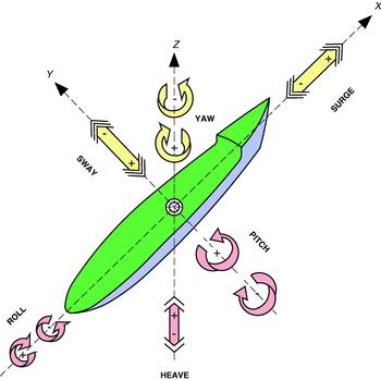
Figure 1. A ship's six DOF's. Drawing: author.
Three of these DOF's are translation motions (surge, heave and sway) and the other three are rotation motions (roll, pitch and yaw)Footnote 2; they can also be differentiated between motions in the horizontal plane (surge, sway and yaw) and oscillating motions in the vertical plane (heave, pitch and roll). The motions in the horizontal plane are unrestored. Therefore, they do not exhibit resonance and their amplitudes in deep water are never greater than the wave amplitude, or in the case of yaw, never greater than the wave slope.
However, when the ship is subjected to motions in the vertical plane, it experiences restoration or restitution forces similar to a damped simple harmonic motion (SHM) and the ship behaves as a spring-mass damper system that can exhibit resonance. Owing to the wave excitation force, a lack of balance is produced derived from the centre of buoyancy B which adopts a new position B′ due to the variation in the underwater volume and, as a consequence of that, the ship's weight acting in G and the buoyancy with the centre in B′ are out of alignment. As a result, a ship's internal righting moment is generated to re-align B vertically with G; however, due to the inertia of the ship's mass, this does not stop in the balanced position, but it exceeds it until a similar symmetric position to the old one is reachedFootnote 3. In short, these three oscillating motions in the vertical plane influence the balance of forces between the weight acting in G and the buoyancy acting in B.
In Naval Architecture, such movements are studied around three mutually perpendicular axesFootnote 4x, y, z. The longitudinal axis of a ship (from bow to stern or from stern to bow) is defined as the x-axis. The rotational motion in the vertical plane around such x-axis is known as roll, with starboard as positive and port as negative (see Figure 2). In addition to the roll, which we have seen is an oscillating motion in the vertical plane, there are two static conditions of inclination around the x-axis: list, originated by an asymmetric distribution of weights and heel, originated by an external force (such as wind or waves) acting on the ship.

Figure 2. The roll motion around the x-axis. Drawing: author.
2. A SHIP's NATURAL ROLL PERIOD
The lack of balance created by the wave system around the ship, which creates the roll motion, generates an internal transversal righting moment in order to recover its balanced situation with G and B acting in the same vertical again (see Figure 3). The magnitude of this righting moment in the ship when the roll takes place depends on the righting arm, GZ, and the weight Δs of the ship (righting moment=ΔsGZ), with GZ=GM TSin θ and for small angles of inclination (θ<10), as Sin θ=θ, the righting momentFootnote 5 is equal to ΔsGM Tθ.
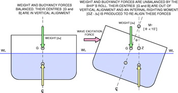
Figure 3. The creation of an internal righting moment by the ship as a response to the wave excitation force which generates a roll motion. Drawing: author.
As a consequence, we can see that the generation of a rotational moment of restitution is produced in response to the excitation force of the wave system; and so, we are in the presence of a rotational SHM similar to the lineal motion of a system formed by a mass linked to a spring by one end and to a damper system by the other. The spring arises from the buoyancy and gravity forces which tend to restore the balance position, i.e. the righting moment [ΔsGZ]; the external exciting force is the force of the waves coming into contact with the ship; the damping effect of the movement is caused by the waves generated by the ship and the viscous friction between its hull and the seawater; i.e. it arises from the interaction between the hull and the water and finally, the mass is the rotational mass or moment of inertia (MOI) of the ship (see Figure 4).

Figure 4. The analogy of the ship's roll motion to a mechanical Spring-Mass Damper System. Drawing: author.
Taking into account that the roll is a rotational motion, the MOI (I x) generated when this motion is produced around the x axis, is not a determined quantity as it may be the mass or the volume, but its value depends on the position of the rotational axis. The MOI is minimum when the rotational axis goes through the centre of the mass. The MOI is similar to the inertiaFootnote 6, except that it is applied to the rotation more than to the linear motion, being able to become a new definition of the mass where the MOI is then a rotational mass. Unlike the inertia, the MOI also depends on the mass distribution in an object. The further the mass is from the rotational centre, the bigger is the MOI in such a way that the MOI “I x” of the mass m of an element around a rotational axis x with a turning radiusFootnote 7k is defined by the formula:
Therefore, Spring constant(k)≡Δs⋅GMT; with Mass (M)≡I x
Continuing the analogy with a SHM whose theory implies that, knowing the parameters m and k of the system, the natural frequency itself is produced by the formula ![]() , it is possible to predict the natural frequency of the ship's rotational oscillating motion around the x-axis, that is to say, the roll:
, it is possible to predict the natural frequency of the ship's rotational oscillating motion around the x-axis, that is to say, the roll:
Considering that for any ship it is difficult and tedious to determine the exact value of radius of gyration of its mass and therefore to calculate the MOI value, it is possible to assume that it is a function of the beamFootnote 8, in such a way that it varies directly with it. So, knowing the relation between the natural frequency of the roll (ωroll) and the roll period (T roll)![]() , formula (2) can be experimentally expressed, referred to the roll period, in the following way:
, formula (2) can be experimentally expressed, referred to the roll period, in the following way:
where: B is the maximum ship's beam (in feet); GM T is the transverse metacentric height (in feet); C is an empiric constant whose value for big ships oscillates between 0·35 and 0·55 (depending on the kind of ship and its cargo situation) when GM T and M are measured in feet. In each case, the value C depends on the ship's capability to damp the rolls. When this value is unknown, 0·44 is applied by default as it usually produces good results.
The equation shows that the bigger the GM T of a ship is, the smaller will be the oscillating period, the bigger the internal response force of the ship will be and the bigger the transverse angular acceleration will be. As with any other rigid body motion, the bigger is the motion acceleration, the bigger will be the damage risks to the crew or to the ship's equipment.
As we know, the GMT can be calculated by measuring the slope of the GZ curve in the origin. For that reason, a ship with a GZ curve with much slopeFootnote 9, shows that it has a large GMT, i.e. a stiff ship and the ship whose GZ curve has a little slope clearly shows that its GMT is small, i.e. a tender ship (see Figure 5). Therefore, in the first case, the ship has very violent roll motions, as it is the typical case of ships with very little length to beam ratio, while in the case that the ship has a small GMT, the roll motions will be much slower. This indicates that the ideal value of a ship's GMT constitutes a compromise between a good seakeeping performance (a small GMT) and a good stability (a large GMT)Footnote 10. Unlike the other two vertical motions heave and pitch Footnote 11, roll comparatively experiences very small damping effects.

Figure 5. Comparison between two GZ curves of static stability corresponding to two ships with different responses. Drawing: author.
3. THE WAVE ENCOUNTER PERIOD
Having examined the analogies of the roll motion and a spring-mass damper system, we can see that the motion created by the excitation force (in this case, the waves due to the pressure variation on the hull) depends on the magnitude of such force and of its frequency. However, except when the ship is at zero speed, the wave excitation frequency does not just depend on the wave characteristics, amplitude and frequency ωw, but also on the ship's speed and course or encounter angle. For that reason, the relevant parameter to consider is the wave encounter frequency ωe, which takes into account the relative speed of the ship and the wave. A complete study of this subject goes further than the content of this articleFootnote 12 and in this section we are only going to see, with the help of Figure 6, how to calculate the wave encounter period in a regular wave system and which methods the ship's master needs to modify if the resonance phenomenon is produced in the roll motion.

Figure 6. Diagram of vectors for the calculation of the wave encounter period. Drawing: author.
Considering that T w is the real wave period; λ is the wave length, and; C w is the wave velocity (more commonly known as celerity) which in the figure falls upon the starboard bow with an angle α; from Figure 6 it is clear that:
Since for any wave, its period comes from the formula ![]() , the wave encounter period (time that the wave crest n° 2 takes to make the distance A-B) will result from the following equation:
, the wave encounter period (time that the wave crest n° 2 takes to make the distance A-B) will result from the following equation:
In Figure 6, α shows the direction where the waves come from. When the ship is sailing in bow or head seas, since α<90°, its Cosine is positive and therefore in this case, the wave encounter period is smaller than its natural period [T e<T w]. On the other hand, with ships sailing in following and quartering seas, since α>90°, its Cosine is negative and as a consequence the wave encounter period is bigger than its natural period [T e>T w]. In beam seas, there is no change and both [T e=T w] are the same. However, the wave encounter length [λe] of a wave that obliquely falls upon the ship's centreline is always bigger either on head seas or on following seas. From this formula, we can clearly see that the ship's master may change the course and/or the speed of the ship in order to modify the wave encounter period; and considering that at sea there is usually little scope for altering the ship's natural roll period, the possibility of modifying the wave encounter period becomes a very valuable tool in his hands when the resonance in the roll motion is produced. This will be analysed in section 4.
4. THE PROBLEM OF RESONANCE IN THE ROLL MOTION
A SHM systemFootnote 13 will experience maximum amplitude oscillations when the excitation force frequencyFootnote 14 is equal to the natural frequency of the system. This situation is called resonance and it is important to make sure that this condition is not produced with the object of reducing the amplitude of any rigid body motion. This may be applied to a ship whose roll natural frequency ωroll, as we have seen, may be estimated. With the object of reducing the ship's roll, it is important that this natural frequency does not coincide with the wave excitation frequency called wave encounter frequency ωe.
Fortunately, the SHM's of the pitch and heave motions are very damped. Although the natural frequency of their respective motions comes in resonance with the wave encounter frequency, this does not imply a significant increment of their own amplitude as they do not come into resonance suddenly due to the fact that the energy is quickly dissipated. However, the small damping which the ship experiences when there is a roll makes it very likely that the natural frequency of this motion ωroll coincides with the wave encounter frequency ωe, in which case the amplitude of motions is significantly increasedFootnote 15 (see Figures 7 and 8 where the different effects of the resonance in the heave and pitch motions can be compared to the roll motion). Resonance may be produced from all motions. However, it is more probable that extreme motions of great amplitude are produced with the roll than with the pitch and heave. As a consequence, due to the noticeable increment of the amplitude of this motion if resonance is producedFootnote 16, different anti-rolling devices are used with the aim of reducing the roll (bilge keels, stabilizer fins, anti-roll tanks, etc are typical examples). The following sections study the effect of bilge keels.

Figure 7. The heave and pitch amplitude of motions versus the respective wave encounter frequency [ωheave and ωpitch] taking into account the natural frequency [ωn] of the ship's motion. In both cases, we can see how their amplitude is not very sensitive to the wave excitation force as they are strongly damped motions. Therefore, the resonance phenomenon becomes less awkward. Drawing: author

Figure 8. The roll amplitude of motion versus the encounter wave frequency [ωroll] taking into account the natural frequency [ωn] of the ship's motion. If we compare this figure with Figure 7 corresponding to the heave and pitch motions, we can see how, unlike these, its amplitude is very sensitive to the wave excitation force as they are very poorly damped motions. Therefore, the resonance phenomenon becomes really awkward. Drawing: author.
5. BILGE KEELS AS ROLL PASSIVE STABILISERS
5.1. General considerations
Roll passive stabilizers do not need energy provision or any control system to operate. There are two categories, dependent on whether they have moving parts or not. The main devices without movable parts are sails and bilge keels. Sailing ships, which frequently sail receiving sea and wind on the beam, have a very effective natural system which dampens roll, due to the sail resistance when following the characteristic ship's roll motion. The change in the lift on the sails varies as the ship rolls and the phase of these lift forces tend to reduce the energy that the ship's roll generates. For this reason, sails are very effective as stabilizers of roll motion for small ships and they have been used in fishing ships with this aim. The required dimension of the sails together with the necessary tackle to rig them limits their use in large ships with mechanical propulsion.
The roll damping effect, derived from the wave generation of a ship, is almost non-existent with regard to the ship's DOF and on the other hand, the possible water flow in eddy circulations is scattered from the bilge due to the rounded shape that most hulls adopt at this areaFootnote 17 forming the named turn of the bilge. As a consequence, there is only viscous friction to scatter the energy derived from the roll. Therefore, a clean, smooth hull has got a very small roll damping capacity unless some appendages are added in order to increase the generation of water flow eddy making and the viscous friction created by its motion.
The simplest and cheapest system of anti-rolling passive devices in a ship with mechanic propulsion is bilge keelsFootnote 18, which may reduce roll amplitude by up to 35%. William Froude (1810–1879)Footnote 19 can be considered one of the promoters of bilge keels. He had been devoted to the study of ships′ motion although his work was specifically related to the ways of reducing roll motionFootnote 20 at sea. But this was before carrying out his notable experiments for the British Admiralty from 1867 using model ships in a test tank which he built at his home, with the aim of determining the ships′ physical lawsFootnote 21. Froude had worked with BrunnelFootnote 22 from 1837 sharing their interest to discover the secrets to predict the ship's behaviour; and when he was present in the sea trials on board the ship “Great Eastern”Footnote 23, his suggestion about the incorporation of bilge keels to reduce roll was finally accepted.
These appendages fixed to each side of the hull are essentially small reinforced plates perpendicularly projected outwards in the bilge and approximately at the height of its turn, being longitudinally fixed to the height of its amidships section and generally being a little longer than half its overall length (see Figure 9).

Figure 9. Longitudinal position of the bilge keel. Drawing: author.
As the ship rolls, the bilge keel quickly takes water that then scatters on its opposite side creating eddies; so there is a very small increment of the added massFootnote 24, but at the same time, there is a significant increment of its damping effect due to the eddies and to the additional friction generated. The design of bilge keels adopts suitable profile and inclination to line with the flow streamlines when the ship is upright and in calm water conditions. Consequently, in this situation, the ship equipped with these appendages has a very small increment of the resistance to forward motion and when rolling, generates a much bigger roll damping effect than its size could suggest, becoming the cheapest anti-rolling device in a ship. Its main function is to be useful to damp the ship's roll motion. Other advantages of these appendages of relative minor importance are serving as a protection to the bilge area in case of grounding, increasing the longitudinal resistance of the hull structure at its level and offering enhanced directional stability.
The main disadvantage is the added resistance to forward motion produced in calm water conditions (when roll reduction is not necessary) and during the ship's navigation at different speeds from that for which the keels were designed since the flow streamlines may no longer be in line with the keelsFootnote 25. There are some situations, due to the kind of navigation or to the type of work a ship does, when bilge keels are not fitted. This happens in ships that generally sail in iced regions, where bilge keels are quite vulnerable to damage and, as a consequence, become detached from the hull with the resulting risk of fissures. It also happens in some fishing ships because there is a potential risk that the nets could catch on the keels whilst being deployed or recovered.
Bilge keels have a tendency to have biofouling growth along their outer edge and on the inferior part along the junction of the hull welding whose increase makes the underwater hull rougher, thus damaging the ship's operational efficiency as it diminishes its speed and increases its costsFootnote 26. The cause is thought to be due to eddy currents that can prematurely deplete antifouling paint coatings. As a consequence, and in order to avoid these inconveniences, it is recommended that both the exterior edges and the inferior part along the junction of the hull welding should be additionally protected with antifouling and anticorrosive painting. This would assure the formation of a suitable film with the aim of optimizing its length of time.
5.2. Design requirements
A bilge keels damping action is relatively small but very effective and with no additional cost after the building of the ship. Its exact position in the ship is carefully studied in order to maximize the hydrodynamic roll resistance and to minimize the hydrodynamic forward motion resistance when the ship is sailing. With such an aim, several positions and dimensions are usually tried during the model ship trials to optimize its service and at the same time to calculate the power requests with each optionFootnote 27. The bilge keel is usually placed in the amidships section of the ship's hull, often perpendicularly at the turn of the bilge.
There are many different ways to build a bilge keel, some of which are the result of elaborate designs, trying to improve its roll damping effect at the same time as its resistance to forward motion is reduced. Although this appendage would not be considered as a critical structural member of the hull, it should be very carefully designed because the region of the hull it is welded to is fairly highly stressed owing to its distance from the neutral axis of turning of the ship's mass.
Bilge keels are aligned with the flow streamlines around the ship moving at design speed in calm water so that its effect is minimum with regard to the increase of the resistance to forward motion. Studies are carried out with model ships concerning the flow visualization during the resistance to forward motion tests. The flow lines are measured along the bilge by means of dyes or small flags so that the bilge keels are set to coincide with them. Thus, dependent on their extent and depth, the additional resistance may be kept to an additional increment of between one and three per cent of that of the main hull.
5.3. Construction
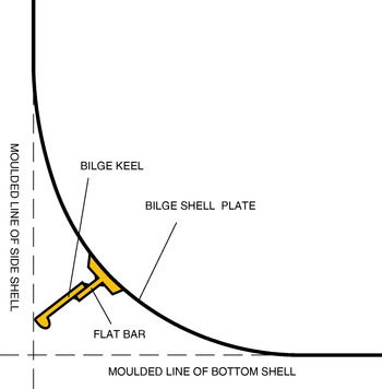
It is very important to build the bilge keels in such a way that the exterior plates to which they are attached stay intact. As a consequence, and in order to avoid damage, their shape as well as their position and their reinforced procedure to the hull are carefully studied. For their protection, the tip of bilge keels should be always arranged so that they lie inside the maximum beam of the ship and above the baseline. If they extended further than these limits, they would be much more exposed to damage risks during docking, dry-docking and in shallow water (see Figure 10).

Figure 10. A standard bilge keel. Drawing: author.
Unless carefully designed, the bilge keel longitudinal endings tend to create areas of stress concentration that may cause fissures on the bilge plating. To prevent this, the bilge keel surface should be gradually tapered-off at those areas and additionally strengthened with a small double plate welded to the bilge plating at the height of a structural resistant element, for instance, a web frame, with the aim that there is a bigger area of transference of the longitudinal stresses between the bilge keel and the hullFootnote 28 (see Figure 11).
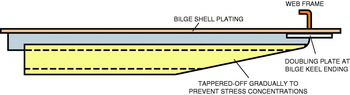
Figure 11. Bilge keel longitudinal ending construction to prevent bilge plating from cracking due to stress concentrations. Drawing: author.
Bilge keels are made of steel plates with their free end or tip strengthened. Generally they are not directly welded to the hull, but to a ground barFootnote 29 previously welded to the hull where the bilge keel is welded over it by means of butt weld. That method forms a junction or weak union so that the butt weld yields quite easily and (if hooked on an obstruction, or if there is a collision or grounding) the bilge keel drops with no hull damage to the strengthened plate. Alternately although less usual, the bilge keel is scalloped throughout its length and may be directly welded to the hull by intermittent welds that conform a weak link to the hull. In large ships, the bilge keel usually has a transversal section with a “V” shape and is internally strengthened at regular intervals (see Figure 12).

Figure 12. A bilge keel for a large vessel. Drawing: author.
5.4. Basis of the bilge keel effectiveness
The friction and roll damping effect of bilge keels increase with the speed v with which they move from one side to the other of the ship; and it depends not only on the roll angular velocity ![]() , but also on the radius k of the circular path of the bilge keel (see Figure 13). So, even the relatively small roll period of a large ship may become very effective to damp its roll, as the value of k generates very high lineal velocities of the bilge keel over the water flow
, but also on the radius k of the circular path of the bilge keel (see Figure 13). So, even the relatively small roll period of a large ship may become very effective to damp its roll, as the value of k generates very high lineal velocities of the bilge keel over the water flow ![]() .
.
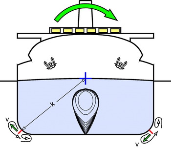
Figure 13. Importance of the radius of gyration k of the added water mass which bilge keels drag in the damping effect of the roll motion. Drawing: author.
In pure simple harmonic motion there is no friction, but naturally when the roll motion takes place the friction, which is always there, increases with the bilge keels. This contributes to damp such motion when dissipating more energy as heatFootnote 30. In this case, the friction has two effects: first, it reduces the angular velocity δθ/δt and therefore the roll slows down and its period increases. Secondly, the friction is directly proportional to the angular velocity δθ/δt and therefore the higher its velocity is, the bigger will be the dissipated energy.
The roll damping action also increases with the square of ship's forward speed and when this translational motion is combined with the rotational roll motion, the water flow moves over the forward end of the bilge keel with an angle of attack that generates a dynamic lift opposed to the roll. However, this misaligns the bilge keel in relation to the direction of the water flow, and therefore creates an additional resistance to forward motion.
Bilge keels offer a significant improvement in the roll damping compared to a ship without them, but their damping effect is smaller than that obtained by other roll stabilizing devices (i.e., controllable fins, passive anti-rolling tanks, active anti-rolling tanks, gyroscopic controlled stabilizers). However, because bilge keels are the only devices which can be used in very rough seas their installation is recommended whenever possible even though other stabilizing devices are set.
The additional damping generated by bilge keels is proportional to their area and it is clear from the results of different tests carried out by different researchers that when the area is the same, in the case of slender ships, the bigger their aspect ratio is, the more effective bilge keels are. However, in full ships with a big block coefficient Cb, the smaller their aspect ratioFootnote 31 is, the more effective they are.
Independently of the specific structural shape they have, bilge keels work in accordance with a very simple, effective theory. To see the effect of bilge keels with regard to the decrease of the natural period of this motionFootnote 32, we start from the formula of the ship's roll natural frequency we saw in section 2, ![]() and from there we get the formula of the ship's roll natural period (provided that the angle of heel induced in the roll is less than 10°) depending on its mass radius of gyration K. We should take into account that
and from there we get the formula of the ship's roll natural period (provided that the angle of heel induced in the roll is less than 10°) depending on its mass radius of gyration K. We should take into account that ![]() ; Δs=M⋅g; I x=K 2⋅M and substituting these values in the formula, we get the following expressionFootnote 33:
; Δs=M⋅g; I x=K 2⋅M and substituting these values in the formula, we get the following expressionFootnote 33:
Each element of the ship individually considered has its MOI which is equal to mk 2. Therefore, the ship's MOI as a whole is defined by the expression I x=Σ(m 1k 12+m 2k 22+......+m nk n2); i.e. the summation of products of elementary masses and the squares of their radius of gyration. As a consequence, the radius of gyration K of the ship's virtual mass when rolling will be ![]() .
.
With the bilge keels projecting themselves from the ship's sides at the height of the turn of the bilge, an increment of the added mass of water m is generated as it moves with the ship's roll with a large radius of gyration k of that water mass, which makes the K value from the equation increase. Consequently, if we take into account the equation of the ship's roll period depending on the radius of gyration of its mass, it is clear that one of the effects of bilge keels is to increase such a period. However, the main effect of bilge keels is due to the increase of viscosity produced as a consequence of the eddies which indirectly generates an increase in the roll resistance. According both to theory and to observation, we can see that bilge keels are more effective in a ship when it moves forward in waves than when it is stopped and not making wayFootnote 34. Such observations suggest that there is a lift at the forward sections of bilge keels. This lift is opposed to the roll motion and it additionally contributes to the ship's course stability. Regarding this, bilge keels are essentially long fins designed in order to give a reaction force when they are moving in relation to the water flow surrounding them (i.e. acting as hydrofoils) and they represent a special application of fixed stabilising fins. Bilge keels should be considered as a means of roll reduction, not designed to achieve its complete elimination as there must be some roll for them to become effective.
5.5. Stresses generated by the roll motion
The racking stresses
The restoring forces generated by the ship as an answer to the wave exciting forces provoking the roll motion initially act over the underwater volume of the ship. The ship's structure must be able to transmit these forces to all the parts over the waterline. These have the tendency to continue their rotation further than the amplitude of the roll itself until the restoring forces are effectively transmitted. This transverse distortion produces stresses in the ship which, known as racking stresses, tend to deform the box section of the hull as a hull girder (see Figure 14).

Figure 14. Racking stresses. Drawing: author.
The tendency to deformation that the hull as a whole suffers (owing to the unequal pressure distribution around the ship that tends to bend side plating and transverse frames) is bigger in the main deck margins and in the turn of the bilges (see Figure 15). At design level and in order to resist the racking stresses in these parts of the ship, reinforcements such as knees, web framing between frames and corner brackets are used.

Figure 15. Areas of the hull under greatest stress due to racking when heavy rolling. Drawing: author.
Torsional stresses due to modification in the distribution of the buoyancy as a consequence of the roll
As a ship heels over, the hull rotates about the waterplane axis, in such a way that the waterplane area becomes more and more asymmetric about the ship's centreline and an excess of buoyancy is produced due to the flares at the fore and aft ends. This generates bending stresses in these areas which cause the hull to bodily rise while the rolling axis shifts away from the centreline towards the excess of buoyancy. However, another effect of these characteristic shapes of a ship is that, as it reaches the maximum roll to both sides, the restoring forces increase more quickly at bow and stern than amidships; thus they expose the ship to twisting or torsional stresses that tend to deform the hull longitudinal structure which consequently must be strong enough as a whole so as to resist these stresses and transmit the excessive righting forces of its ends towards the amidships area to minimize the twisting. The object of this is to minimize the torsional forces produced when the ship reaches the maximum roll. That is why it is necessary to incorporate reinforcement all along the length of the ship so that its structure does not get damaged.
Bilge keels as elements of structural reinforcement
As we have seen, bilge keels are placed in an area where big racking stresses are generated when rolling. Therefore, the whole area of the bilge needs to be specially strengthened and the bilge keels suitably built, will help to reinforce structurally such areas. On the other hand, the torsional stresses produced with the roll justify (as we have pointed out in 5.3) the necessity that the width at their ends decreases progressively in order to get a suitable transmission of the bilge keel's efforts to the hull to minimize the risks of possible cracks.
6. CONCLUSIONS
Of the three ship's DOF's at sea (heave, pitch and roll), which have some analogies with a spring-mass damper system, the roll motion is the one which presents less damping and therefore, it is the most probable one to enter resonance thus increasing drastically the amplitude of motion. So, particularly since the introduction of mechanical propulsion in ships during the second half of the nineteenth century, it has been necessary to incorporate anti-roll systems; bilge keels are a passive system with no movable parts and are incorporated in almost all ships.
This article, which introduces roll motion study whose considerations help as an initial basis to understand any anti(-rolling system, has been specifically oriented to the study of bilge keels from the constructive and operative point of view, trying to show the effects produced in a ship, particularly emphasizing effectiveness. In short, the bilge keels effect is produced by:
• The increase of the ship's roll natural period and;
• The generation of a damping moment resulting from the viscous eddy flows around their surface, the pressure resistance around it and the hydrodynamic lift in the forward sections of bilge keels.
Due to the different origin of the aspects which determine their functionality, there has not been unanimity among the authors when defining it in a general senseFootnote 35, using terms such as stabilising, damping or reduction effect, although it seems that “stabilising” is the most accepted term.
Starting from the analogy of the roll motion with a spring-mass damper system, the formula of a ship's roll natural period has been deduced and it has been shown why bilge keels contribute to increase the radius of gyration of a ship's mass and therefore its roll natural period. Taking into account that at sea, in general, the ship's master cannot modify the ship's roll natural period, supposing this motion comes in resonance with the wave encounter period, the only good seamanship at his/her hands is to modify the wave encounter period by changing ship's course and/or the speed.
The effect of bilge keels on the ship's roll damping is quite complex and depends on a lot of factors such as the keel's area, its aspect ratio, the kind of ship and its speed and depth, the radius of gyration of the ship's mass, the GMT and the bilge shape. With regard to the configuration, efficiency and building of bilge keels, many theoretical as well as experimental results have been published. However, in spite of the progress achieved in its design, there is a current need to continue investigating more sophisticated methods to determine the best parameters of bilge keels for each ship.