1. INTRODUCTION
Autonomous Underwater Vehicles (AUVs), a multi-disciplinary overlapping research area, has received extensive attention from all over the world, and great strides have already been made (Jiang et al., Reference Jiang, Feng and Wang2000). In the military, AUVs can be used for reconnaissance, communications relay and “smart” guided attack. In the civil context, AUVs can be used for exploration and sampling marine resources, surveying seabed topography, salvage, sediment sampling, monitoring the marine environment, maintenance of marine engineering and monitoring dam safety (Sang et al., Reference Sang, Pang and Bian2003; Hagen et al., Reference Hagen, Midtgaard and Hasvold2007; Li et al., Reference Li, Chang, Sun and Su2007).
When the above tasks are performed, accurate underwater navigation and positioning is essential. This is especially true for long duration and long distance underwater navigation. Navigation and positioning accuracy becomes the key factor that directly affects whether the scheduled tasks can be completed (Zhang et al., Reference Zhang, Li and Wang2006; Yan et al., Reference Yan, Li and Yuan2002). Underwater navigation and positioning methods include underwater acoustic navigation, dead reckoning navigation and inertial navigation (Jiang et al., Reference Jiang, Feng and Wang2000; Leonard et al., Reference Leonard, Bennett, Smith and Feder1998). In many cases, the navigation methods are used together. For example, Lee et al. (Reference Lee, Jun, Choi and Hong2005) and Willumsen et al. (Reference Willumsen, Hallingstad and Jalving2006) proposed a fault tolerant navigation system combining underwater acoustic navigation with dead reckoning and inertial navigation that was robust for initial errors. Holtzhausen et al. (Reference Holtzhausen, Matsebe, Tlale and Bright2008) proposed an AUV status tracking method, which is realised by Kalman filtering of multi-sensor information fusion data. With the corresponding experiments based on these mature navigation methods, a lot of positive results have been obtained (Jalving et al., Reference Jalving, Gade and Svartveit2004; McTrusty and Dudinsky, Reference McTrusty and Dudinsky2003; McPhail and Pebody, Reference McPhail and Pebody1997; Donovan, Reference Donovan2012). However, underwater acoustic navigation (including long-baseline, short-baseline and ultra-short baseline) need a support acoustic array deployed; independent operations for AUVs are not favoured, and navigation and positioning range is limited. Dead-reckoning and inertial navigation are the main navigation methods for AUV underwater operation. The main characteristic is that positioning error accumulates over time; a large error will be produced for long duration underwater navigation, so external information is needed for error correction. The typical method for AUV is surfacing to receive Global Positioning System (GPS) signals to correct the error. Frequent surfacing is inefficient for long duration AUV underwater operations and the relatively small size of most AUVs mean large sea waves can cause particular problems.
With the emergence of accurate underwater terrain survey methods, Underwater Terrain Matching Navigation (UTMN) has become a feasible method to solve these problems. This means that “Long duration, secret, all-weather and high-accuracy” navigation has been realised. Furthermore, the AUV becomes more practical and can achieve long duration positioning accurately without external sensors, surfacing correction or accumulated error. Therefore in recent years, UTMN methods have been intensively studied, and a lot of results have been achieved (Carlstrom and Nygren, Reference Carlstrom and Nygren2005; Anonsen and Hagen, Reference Anonsen and Hagen2010; Nakatani et al., Reference Nakatani, Ura, Sakamaki and Kojima2009; Carreno et al., Reference Carreno, Wilson, Ridao and Petillot2010).
2. RESEARCH STATUS OF UTMN
With the increasing requirements for AUV navigation and positioning accuracy, UTMN technology has seen rapid development. A number of research institutions and organisations are working on related technology research, have developed some corresponding hardware and software systems and conducted sea trials. Some of the renowned institutions include the Norwegian Defence Research Establishment (FFI), Royal Institute of Technology (KTH), Stanford University, and the University of Southampton. Some representative UTMN systems are summarised below.
2.1. FFI-developed UTMN technology and system
As a well-known commercial AUV development institution, FFI develops the HUGIN AUV (Figures 1 and 2). As their masterpiece, HUGIN plays an active role in various fields. FFI has also conducted some theoretical and experimental UTMN technology research. Before sea trials, they developed the TerrLab, which is a terrain simulation system used for UTMN playback simulation. In order to verify the real-time navigation accuracy, FFI conducted two sea trials in 2009 and 2010. In 2009, a 50 km underwater trial was completed in the open sea between the Norway coast and Bering Island. In the trial, HUGIN did not accept any other location updates; all location updates were provided by the UTMN system. Upon arrival at the destination, the difference between the underwater acoustic positioning and terrain positioning was 4 m. Another sea trial was carried out in Oslo Gulf, May 2010. During the trial, the multi-beam sonar used for bathymetry was suddenly broken, so the Doppler Velocity Log (DVL) was temporarily used for bathymetry measurement. After five hours' underwater sailing, the error compared to the GPS signal was about 5 m (Anonsen and Hagen, Reference Anonsen and Hagen2010; Anonsen et al., Reference Anonsen, Hallingstad and Hagen2007; Hagen et al., Reference Hagen, Anonsen and Mandt2010; Anonsen and Hagen, Reference Anonsen and Hagen2009; Hagen, Reference Hagen2006; Hagen and Anonsen, Reference Hagen and Anonsen2014). FFI has researched the UTMN for many years, and thus produced many important references.

Figure 1. HUGIN 1000 AUV.
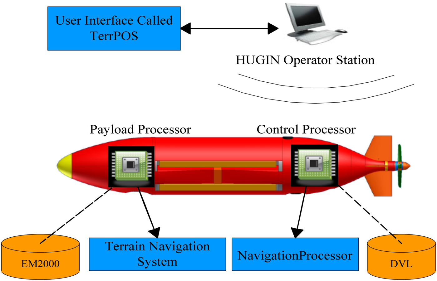
Figure 2. Terrain navigation system of HUGIN 1000.
2.2. The UTMN research by Professor Nygren and the KTH team
Through refitting a torpedo shell, this team has built two types of AUV: AUV62 F and Sapphires (see Figures 3 and 4). The terrain-aided navigation system software in both of them was identical, AUV62 F used more than 400 real-time terrain measurement beams, Sapphires used synthetic aperture sonar to measure terrain, and the system used a terrain correlation method. During the sea trial in October 2002, they chose eight match points over a 65 km distance; the final positioning error was below 10 m (Carlstrom and Nygren, Reference Carlstrom and Nygren2005; Nygren, Reference Nygren2005; Nygren, Reference Nygren2008).

Figure 3. AUV 62 F.

Figure 4. Sapphires AUV.
2.3. Stanford University and Monterey Bay Aquarium Research Institute
This team collaboratively researched a long voyage, low-cost AUV terrain navigation method. In contrast to traditional terrain navigation, they used low-cost sonar and a low-cost Inertial Navigation System (INS), researched the influence of the terrain navigation result under differing drift error and heading uncertainty. In April 2008, a sea trial using the “MBARI Dorado” AUV (see Figures 5 and 6) was conducted in Monterey Bay, California. The sea trial studied terrain-aided navigation sensitivity using a multi-beam echo sounder, DVL and depth sensor, quantitatively analysed the influence factors of navigation convergence distance and validated the terrain-aided navigation feasibility using a low-precision sensor. Using the low-precision dead reckoning and terrain navigation filtering, the navigation accuracy can reach 4-10 m (Meduna et al., Reference Meduna, Rock and McEwen2010; Meduna et al., Reference Meduna, Rock and McEwen2008).

Figure 5. MBARI Dorado AUV.

Figure 6. Configuration of Dorado AUV.
2.4. “Autosub 6000” AUV
The Autosub 6000 (Figures 7 and 8) developed by the University of Southampton, used a striped underwater terrain map as the reference underwater digital terrain map. The AUV sailing direction was perpendicular to the reference terrain. When the AUV passed through the reference terrain, terrain-matching location was executed, and the positioning result was used for correcting dead reckoning error. Using the experimental data, the effects of matching the results with different sensor deviations were discussed, navigation error was analysed by the filtering method, and the limitations of this method in real-time navigation calculations were studied (Meduna et al., Reference Meduna, Rock and McEwen2010; Morice et al., Reference Morice, Veres and McPhail2009).

Figure 7. Autosub 6000.

Figure 8. Terrain navigation test of Autosub 6000.
2.5. University of Tokyo and the Japan Agency for Marine Engineering Research Institute
This team developed the open-frame AUV “Tuna-Sand” (Figure 9), which was used for submarine target recognition and resource exploration. Using a multi-beam sensor, terrain-aided matching navigation was studied. In the terrain navigation test that was executed in the Kagoshima sea area in 2008, in a region of 400 m × 400 m, with 3 m grid precision, the terrain matching test was completed by real-time multi-beam sonar measurements, and the matching results were used for underwater precise positioning of the hydrothermal probing. After comparing with the inertial navigation equipment, the expected goals of terrain matching accuracy were achieved (Nakatani et al., Reference Nakatani, Ura, Sakamaki and Kojima2009; Nakatani et al., Reference Nakatani, Ura, Ito, Kojima, Tamura, Sakamaki and Nose2008; Ura et al., Reference Ura, Nakatani and Nose2006).

Figure 9. AUV “Tuna-Sand”.
2.6. Other research
Kimball and Tock (Reference Kimball and Tock2011) studied terrain navigation for an AUV operating in an iceberg area. Stalder et al. (Reference Stalder, Bleuler and Ura2008) studied the possibility of using side-scan sonar images for terrain navigation. Batista et al. (Reference Batista, Silvestre and Oliveira2013) studied terrain navigation based on a multiple model adaptive estimator. As a new navigation methodology, UTMN has been studied for several years, and which method to use depends on the sensor configuration and algorithm efficiency. As in the sea tests, the application performance of various algorithms will be further tested.
3. THE COMPOSITION AND PRINCIPLE OF UTMN SYSTEMS
The basic structure of UTMN systems is shown in Figure 10, the main components include basic navigation unit, depth measurement unit and terrain matching unit.

Figure 10. Configuration of UTMN system.
3.1. The basic navigation unit
In a UTMN system, the basic navigation unit provides the initial positioning for the terrain matching unit. Typically, the basic navigation unit is an INS or dead reckoning system.
3.1.1. Inertial Navigation System
An Inertial Navigation Systems (INS) (Sun et al., Reference Sun, Wan and Pang2010) is the navigation system that measures carrier motion with inertia components and estimates the object position, attitude and velocity. Gyroscopes and accelerometers are the inertial components used by INS. The Gyroscope defines the navigation coordinate, then obtains the heading and attitude angles; the accelerometer measures the AUV acceleration. Two integrations of the acceleration can obtain the distance, and the current position of AUV can be continuously deduced.
3.1.2. Dead reckoning navigation
Dead Reckoning Navigation (DRN) is one of the most basic navigation methods, from a known position coordinate, based on the current heading, speed and journey time information, the position of AUV can be reckoned by an appropriate algorithm at the next time, to thereby obtain real-time status information of the AUV. The main advantage of DRN is fewer sensors and low cost and the AUV can be positioned at any time. The main disadvantage is that with the passage of time, there is accumulated error, which, if not corrected by a periodical input such as from GPS, over a certain range, will increase dramatically.
3.2 The depth measurement unit
The depth measurement unit is used to measure the depth values where the location of AUV is, and compare the extracted matching terrain features and digital terrain maps. As shown in Figure 11, the water depth includes the distance from AUV to the sea level and the distance from AUV to the sea bottom, the former is generally called draft depth, shown with Depth, the latter is called the height, shown with Height, and the sum of Depth and Height is indicated by the depth value.

Figure 11. Underwater Depth reference sketch.
The Height measurement methods contain single beam measurement and a multi-beam measurement. The single beam measuring sensor is the acoustic altimeter, also called a single-beam echo sounder. The bathymetric process of a single beam echo sounder is that a short pulse of sound is emitted vertically downwards by a transducer, the pulse wave will be reflected when it reaches the seafloor, and a sonar echo is received by the transducer (Zhai, Reference Zhai2010). The Height is determined by the two-way travel time of sound waves in seawater and the average sound velocity in the water medium.
 $$D_{tr} = \displaystyle{1 \over 2}Ct$$
In the formula, D tr is Height, C is the average velocity in water, t is two-way travel time of sound wave.
The actual water depth D can be obtained by the sum of Height D tr, the Depth ΔD d and tidal correction value ΔD t.
 $$D = D_{tr} + \Delta D_d + \Delta D_t $$
A Multi-Beam Echo Sounder (MBES) is a kind of water depth measurement equipment that can achieve large-scale, high-precision depth measurement; many bathymetric measurement values perpendicular to the direction can be obtained at the same time. The interference principle MBES can obtain thousands of bathymetric points, the beam incident angles can be detected by comparing phase difference between two given transducer receiving units. As the incident angle increases, the phase difference will also increase, and the detection accuracy is also significantly improved (Li, Reference Li2006; Gao et al., Reference Gao, Liu and Zhang2014). A schematic diagram of single beam and multi-beam bathymetry survey is shown in Figure 12.

Figure 12. Bottom topography measured by single beam and multi-beam sonar (a) Single beam; (b) Multi-beam sonar.
3.3. The terrain matching unit
The terrain matching unit is the core of UTMN, It includes three parts: real-time depth data processing, an underwater digital terrain map and a terrain matching algorithm.
In contrast to land measurement, the influence of the marine environment and an AUV's irregular motion, the underwater measurement is time-varying and dynamic. At the same time, underwater terrain surveys are also affected by the motion and intrinsic nature of seawater (Huang et al., Reference Huang, Zhai and Ouyang2003). These effects are collectively referred to as noise, and the influence on marine measurement is much more serious than for land measurement. The MBES system is constituted of a variety of sensors, so measurement error has significant multiple sources. The data quality depends not only on the system characteristics, but also on the auxiliary equipment (Liu and Zhao, Reference Liu and Zhao2002; Zhang et al., Reference Zhang, Li, Zhao and Rizos2014). The real-time depth data processing section includes the following steps: real-time depth data filter, sound velocity correction, tide correction, spatial gesture conversion, terrain feature extraction, and so on.
The underwater digital terrain model is the stored digital map. The terrain model for a UTMN system is the set of bathymetric data points within a certain region. It is composed in the form of a grid and the resolution of the digital terrain model is the grid interconnection distance. The smaller the grid interconnection distance, the higher the terrain resolution, and thus terrain is more accurately mapped.
The matching algorithm is the core of the terrain-matching unit, in the case of the known underwater digital map, the matching algorithm compares real-time measurement data with the depth sequence at the position indicated by the basic navigation unit, and provides a more accurate update to the position of the AUV.
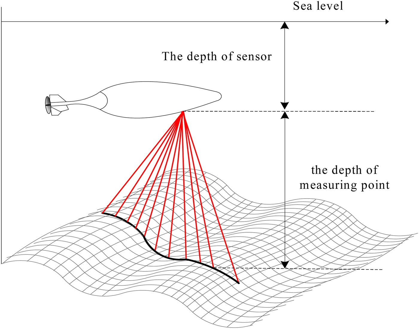
3.4. The principle of UTMN
When an AUV is sailing in the terrain matching area, measurement points over a variety of terrain profiles is measured by the MBES system, and the sum with the depth value obtained by a hydrostatic pressure sensor is the water depth (in Figure 13, the relative distance between the sensors is omitted). Using real-time measurement terrain matching surface information, the matching algorithm determines the best matching position. The underwater terrain-matching positioning principle is shown in Figure 13.

Figure 13. Sketch of underwater terrain matching positioning principle.
The UTMN system can be seen as an independent part of the navigation system, its main function is to provide a position measurement. Similar to the GPS signal, the UTMN system position measurement will be integrated with the INS. The UTMN system can also be integrated with a DRN system, or treated as a separate location update source. For INS and GPS, UTMN systems can provide additional position estimation, and the integrity of the navigation system is improved.
4. UTMN METHODS FOR AUV
As an aid to navigation technology, terrain-matching navigation has been studied for many years. Land terrain navigation has been validated in aircraft and cruise missiles (Hu et al, Reference Hu, Zhu and Xia2008; Bergman et al, Reference Bergman, Ljung and Gustafsson1999). UTMN for AUV has been developed based on land terrain matching navigation. However, in contrast to land terrain navigation, AUV underwater terrain matching navigation has its own characteristics, mainly manifested as follows.
• The speed of an AUV is much slower than an aircraft, and the terrain range of AUV traversal is limited, so the matching characteristics are relatively small. Meanwhile, the underwater terrain is often relatively flat with few terrain signs, so the matching is difficult.
• The volume of an AUV is small, it is impacted by ocean currents and other environmental disturbance forces and there is sway in its motion. Thus sensor terrain data needs to be corrected.
• It is relatively difficult to establish an underwater digital terrain map. A high precision land terrain map can be obtained using satellite remote sensing technology, but the underwater digital terrain map needs to be interpolated from an electronic chart, or obtained from MBES data. The former is easy to obtain but the accuracy is low; the latter has high accuracy but handling is difficult.
• The sensor data errors need to be considered by the acoustic sensors, and fault-tolerant processing is required. The corrected error of the matching algorithm is an additional consideration.
4.1. The advantages of Multi-beam bathymetry in UTMN
As a type of high-precision measurement equipment, the MBES system is widely used in submarine terrain survey, ocean engineering investigation and hydrographic survey (Luo, Reference Luo2003; Hu et al, Reference Hu, Zhu and Xia2008). In recent years, as UTMN technology has developed, the MBES system has played an important role in UTMN research. Using MBES in a UTMN system has huge advantages, which are detailed as follows:
The first advantage is in production of underwater digital terrain maps (UDTM). The traditional UDTM is obtained from the electronic chart, and the minimum spacing between the electronic chart soundings is generally 100 metres, so the accuracy requirements cannot be achieved. In order to establish the UDTM, reducing the spacing of measurement points by interpolation calculation is usually used to obtain a higher resolution (Liu et al, Reference Liu, Ruan and Wu2004). However, due to the complexity of the submarine terrain, it is difficult to ensure the authenticity of the terrain of the UDTM obtained by interpolation. For the characteristics of high accuracy and full coverage, the UDTM established by MBES data has high resolution, and is ideally suited for UTMN.
Secondly, in real-time terrain measurement, hundreds of sounding points can be obtained instantly by MBES, and using interferometry MBES, even thousands of sounding points can be obtained in an acoustic pulse, so a highly efficient method for getting the real-time terrain matching sounding point is provided by MBES and the real-time requirement of UTMN is achieved.
Third, in the contained terrain information, within a given distance, a “line terrain” is obtained by single-beam bathymetry; but through a combination of acoustic pulses, a “surface terrain” is obtained by multi-beam bathymetry and the terrain information is much richer than single beam.
Finally, in the terrain characteristics established, the spacing measurement error is introduced by single beam measurement, with the increasing measurement points, the measurement terrain deviation is also increasing, and the matching result will be affected. The “surface terrain” is constituted of multiple “line terrains” which is measured by MBES. When terrain characteristics are rich, the matching only needs a line terrain, the cumulative error will not be brought in; when the multiple line terrain needs to be combined, the number of pulses needed is much smaller, and the effect of accumulated error is low.
With the development of multi-beam bathymetry technology, in beam forming theory, the interferometry MBES system has been developed (Zhao and Liu, Reference Zhao and Liu2008). Compared with traditional beam-controlled MBES systems, greater data density and higher resolution is available, and the implementation of the underwater terrain matching will be more effective. As can be seen from the above analysis, using multi-beam sounding to UTMN has huge theoretical advantage.
4.2. The UTMN methods for AUV based on multi-beam bathymetry
UTMN methods have been studied for many years, but the majority of contents follow the land terrain matching navigation research approach, that is terrain matching based on single-beam measurement. Therefore, it is necessary to analyse the applicability of UTMN in multi-beam bathymetric conditions. Through the analysis of terrain matching navigation principles, the UTMN methods based on multi-beam bathymetric are as follows.
4.2.1. Correlation-based approach
The TERCOM method is the most famous correlation-based approach, which is widely used on cruise missiles and aircraft. The theory of TERCOM is correlation analysis of the elevation profile and interpolation of sectional sequences in the corresponding area of the DTM, of finding the maximum correlation point and the matching position point, and thus correcting the navigation system.
Similar to the land terrain matching method, by measuring one or several depth data sets as a real-time terrain profile correlation analysis can be conducted with the UDTM data. Using the corresponding correlation algorithm, the best matching position can be determined. The matching mode is developed from traditional “line matching” to “surface matching” for the MBES used (Chen, Reference Chen2013). The principle of correlation matching method based on MBES is shown in Figure 14.
Figure 14. Correlation method principle of underwater terrain matching.
4.2.2. Approach based on extended Kalman filtering
SITAN is the most typical terrain matching method based on an Extended Kalman Filter. Through continuous sampling of the terrain data, the method employs recursive processing of each terrain elevation value using a Kalman filter. Through linear processing the terrain to calculate the terrain slope, while taking advantage of the height from the ground, the status information is estimated, further the navigation information is corrected. Because the slope estimation bias could be easily led by terrain linear processing, the filter is easily dissipated.
Though SITAN has been improved by many scholars, the terrain linearized problem is still an important factor that constrains algorithm performance (Fellerhoff and Creel, Reference Fellerhoff and Creel1986). Figure 15 shows the schematic of the SITAN terrain matching method.

Figure 15. SITAN principle of land terrain matching navigation.
The multi-beam profiles are multi-dimensional bathymetric points, when terrain linearized, the dimensions of terrain linearization in the filtering equation are sharply increased and the algorithm becomes complicated. In this case, terrain-matching navigation using MBES and Kalman filtering based on continuous measurement is not applicable.
4.2.3. Approach based on direct probability criterion
The direct probability criterion methods change the state estimation problem to finding a probability density function, and the maximum probability value is the best estimate. Meanwhile, because a system error model is not a special requirement, the non-linear model can be processed directly. For a terrain-matching problem in a non-linear state, this method has advantages.
Bergman et al. (Reference Bergman, Ljung and Gustafsson1999) first handled terrain height matching using Bayesian estimation. In further research, using Bayesian estimation to solve the terrain-matching problem is widely used in land terrain matching navigation (Bergman, Reference Bergman1998; Baraka and Le Gland, Reference Baraka and Le Gland2010). The advantages of using multi-beam sonar in the terrain measurement, using Bayesian estimation theory to solve the underwater terrain navigation, will be extremely attractive.
4.2.4. Approach based on image matching
Because the multi-beam sonar image can be regarded as a grey-scale image, underwater terrain-matching can be seen as a special kind of image matching method; in this regard, some preliminary research has been carried out. Stalder et al. (Reference Stalder, Bleuler and Ura2008) studied the possibility of terrain navigation using side-scan sonar images; Garcia et al. (Reference Garcia, Puig, Ridao and Cufi2002) presents a position estimation method for AUV which associates terrain image information with Kalman filtering; Lerner and Rivlin (Reference Lerner and Rivlin2011) proved the feasibility of using only captured images for navigation. Williams et al. (Reference Williams, Newman, Rosenblatt, Dissanayake and Durrant-Whyte2001) realised synchronous composition and positioning within a small range by scanning sonar. Xu et al. (Reference Xu, Wu, Xu, Wang and Li2014) proposed a Iterative Closest Contour Point (ICCP) algorithm based on affine correction. There are some differences in the matching methods used compared with the traditional underwater terrain navigation methods, however, the essence is still using terrain information for navigation.
5. FUTURE RESEARCH IDEAS FOR UTMN OF AUV
UTMN is mainly used for real-time and accurate navigation and positioning when AUV are engaged in long duration underwater sailing. Through analysing the existing literature, the process of UTMN are summarized as follows. First, measuring the underwater terrain of an AUV predetermined sailing area by MBES and making the UDTM; then, when the AUV is sailing in the area, extracting the real-time terrain data by terrain measurement sensors; at last, matching the real-time terrain and UDTM data and getting the position of AUV. Through summarising and extending the existing research, the research scheme of UTMN is as shown as follows:
The existing research only focuses on a particular aspect of UTMN, and most have been verified by comparing aircraft terrain matching to underwater, and the matching result is not fused with other navigation modes; there is no complete research system. The Research scheme in Figure 16 is the proposed complete process to allow UTMN to become really practical, and there are some noteworthy research fields in Figure 16 as follows:
• When underwater terrain matching, the navigation accuracy is directly affected by UDTM. In the existing underwater terrain sounding technologies, MBES has high accuracy and efficiency, so it is necessary that analysis of the sounding characteristics of MBES and in-depth study of the post-processing methods of MBES data be conducted to build a high accuracy UDTM system.
• Real-time terrain data is the means for terrain matching, so it is necessary to build a suitable terrain matching model, which needs to research real-time bathymetric data filtering methods and high accuracy reconstruction interpolation modes of underwater terrain.
• The matching algorithm is the most pivotal issue to ensure the accuracy of terrain matching. Therefore, it is an important step to study a high confidence-matching algorithm which is suitable for UTMN.
• When AUV underwater sailing, the navigation system uses multiple ways to navigate. So the ultimate goal of the underwater matching research is studying multi-source navigation modes, the data fusion methods between terrain matching navigation and other navigation results, and establishing an underwater navigation system that has high accuracy and high reliability.

Figure 16. Research scheme of underwater terrain matching navigation.
6. KEY ISSUES WHICH NEED TO BE ADDRESSED
AUV underwater terrain matching navigation is a relatively new research field, and some results have been acquired, but the following aspects of problems need to be addressed:
• Real-time terrain data collection and modelling based on multi-beam sonar.
• High-precision modelling of underwater terrain.
• Research of high confidence underwater terrain matching algorithms.
• The data fusion method and theory of terrain matching positioning and other navigation modes.
• The error analysis and fault-tolerant processing problems of UTMN.
7. CONCLUSION AND DEVELOPMENT TRENDS
UTMN is an important method for AUV long duration and accurate underwater navigation, but development has so far been constrained. As multi-beam bathymetric technology, computer technology, electronic technology, communication technology and control technology all develop, UTMN will achieve better research results. The development trends of AUV underwater terrain matching navigation technology are as follows:
• The advantages of good concealment, independence and wide application range which are UTMN characteristics will be further reflected in the development of UTMN technology for AUV;
• AUV navigation system will be developed toward the direction of integrated navigation. An integrated navigation solution of “inertial navigation + terrain matching navigation” will have more widespread application;
• The new technologies and new methods (such as the new MBES, new terrain matching algorithms) will strengthen the function of UTMN in AUV navigation systems.
Currently, UTMN has demonstrated great potential for development, and has become a hot research topic of AUV underwater navigation technology. Several research institutions of have made many achievements, but there is still a long way to practical application. AUV underwater terrain matching navigation is bound to be more widely used as related disciplines also develop rapidly.
FINANCIAL SUPPORT
This work was supported by the National Natural Science Foundation of China (grant numbers 51279221, 51179035); and the Natural Science Foundation of Heilongjiang Province (rant numbers E201121).