INTRODUCTION
GPS has been efficiently used for a majority of applications in marine geodesy, hydrography, navigation and oceanography. The fields of application are continuously broadening. The positioning accuracy requirements of these applications vary from a few centimetres to several metres. For instance, a single C/A-code receiver can be sufficient for applications requiring low accuracy. Alternatively, some marine applications (e.g. precise hydrographic surveying; monitoring silt accretion and erosion in rivers, lakes, estuaries, coastal waters and harbour areas; marine geodynamics; attitude control of ships, buoys and floating platforms) require high accuracy better than 0·1 m in position and height. In this case, single or dual frequency geodetic-grade GPS receivers that measure carrier phase have to be used (Seeber, Reference Seeber2003).
In contradiction to geodetic-grade receivers, OEM or navigation (handheld) type receivers that can output carrier phase data have been recently used in positioning for different purposes (Abidin and Muchlas, Reference Abidin and Muchlas2005; Alkan et al., Reference Alkan, El-Rabbany and Saka2007a, Reference Alkan, El-Rabbany and Sakab; Alkan et al., Reference Alkan, Saka, Kalkan and Şahin2008; Cosser et al., Reference Cosser, Hill, Roberts, Meng, Moore and Dodson2004; Hill et al., Reference Hill, Moore and Dumville2001; Jang and Kee, Reference Jang and Kee2006; Masella, Reference Masella1999; Rizos et al., Reference Rizos, Han and Han1998; Saeki and Hori, Reference Saeki and Hori2006; Schwieger and Gläser, Reference Schwieger and Gläser2005; Söderholm, Reference Söderholm2005, Wang et al., Reference Wang, Lachapelle and Cannon2004). The cost of such a system is less than US$1,000 and thus they may significantly reduce the positioning equipment cost.
The main purpose of this study is to investigate the use of a developed low-cost carrier phase–based GPS positioning system (i.e, OEM-type GPS receiver) for kinematic applications and to assess the accuracy of the proposed system. Furthermore, a zero baseline test was carried out to evaluate the performance of the OEM receiver. In the following sections, the constituted low-cost positioning system is described and all test procedures and their results are discussed in detail.
DESCRIPTION OF THE DEVELOPED LOW-COST POSITIONING SYSTEM
In this study, a Thales Navigation, now Magellan Professional, AC12 OEM GPS receiver was used. The main components of the developed low-cost positioning system are shown in Figure 1.

Figure 1. Schematic diagram of positioning system used in the study.
The AC12 receiver uses only single frequency observations with an output rate limited to 1 Hz. It provides precise carrier phase outputs and thus produces high-accuracy for many applications, including land and marine navigation, low-cost heading and attitude systems, deformation monitoring, asset and personnel tracking and relative navigation. Some important features can be highlighted as follows:
• Low-cost, high performance GPS solution
• Precise carrier-phase tracking
• Raw data output (code and carrier)
Some of the technical specifications of the receiver are given in Table 1. Details can be also found in Thales (Reference Thales2005). AC12 receivers do not have internal memory and must be connected to a data logger (e.g. a laptop) through its serial port to record GPS data. In order to receive raw data (both pseudorange and phase data) a Windows based software, Ashtech Evaluate, is used (Figure 2). The software enables users to interface with AC12 receiver for viewing, logging and analyzing the performance of features. It has a simple terminal program that gives an option to open a terminal screen to communicate with the receiver by sending preset command strings, user-defined command strings, or individual set or query commands (Ashtech, Reference Ashtech1997).

Figure 2. A sample screenshot of Ashtech Evaluate software.
Table 1. Some specifications of the AC12 GPS receiver (Thales Reference Thales2005).

ZERO BASELINE TEST
A test called zero baseline can be carried out in order to evaluate the receiver performance and to obtain an impression of the measurements' noise characteristics. In this test two or more receivers are connected to an antenna. Due to the use of a single antenna, the baseline components between receivers should all be identically zero. In the zero baseline test, a number of error sources associated with GPS including atmospheric effects, satellite ephemeris and multipath errors can be cancelled since the effects of these error sources are regarded as the same at both receivers. The test would give an idea of the GPS receiver's carrier phase measurement accuracy (Rizos et al., Reference Rizos, Han and Han1998; Hill et al., Reference Hill, Moore and Dumville1999; El-Rabbany, Reference El-Rabbany2006; Amiri-Simkooei and Tiberius, Reference Amiri-Simkooei and Tiberius2007; Hofmann-Wellenhof et al., Reference Hofmann-Wellenhof, Lichtenegger and Wasle2008). The aim of our experiments was to compare the geodetic and the low-cost OEM GPS receivers with respect to accuracy performance and noise level.
In this frame, two zero baseline tests were performed on geodetic-grade and low-cost OEM GPS receivers in two consecutive days, on September 30 and October 1, 2008, respectively. It should be noted that, to provide the same geometry between satellite and receiver, the second test was started after one sidereal day. In the first test, two Ashtech Z-Xtreme geodetic-grade GPS receivers were connected to a dual frequency Ashtech geodetic GPS antenna via a GPS antenna signal splitter and the data were independently recorded for further analysis. In the second test, two AC12 GPS receivers sharing the same antenna were used. GPS data were collected in three independent sessions which lasted 30, 60 and 120 minutes at a 2-second interval in static mode. The measurements were carried out on the roof of the Civil Engineering Faculty, ITU to provide favourable observability conditions. The schematic depiction of the zero baseline tests are given in Figure 3.

Figure 3. Schematic diagram of zero baseline test for geodetic-grade (left) and low-cost GPS receivers configuration (right).
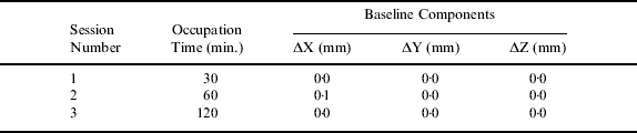
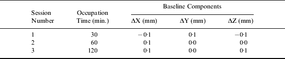
The collected data were processed by Leica Geo Office (LGO) software as a static session. During the process, the Saastamoinen and standard models were used to model tropospheric and ionospheric delays. The estimated baseline components are given in Tables 2 and 3. As can be seen from the tables, almost all baseline components are obtained as zero for geodetic receivers. The only exception is found in the X components (0·1 mm) in the second session. For OEM receivers most of the baseline components are calculated as 0·1 mm. It should be noted that the baseline components between the two receivers should ideally be zero.
Table 2. Estimated baseline components from the zero baseline tests (for geodetic-grade receiver pairs).

Table 3. Estimated baseline components from the zero baseline tests (for low-cost receiver pairs).
The L1 phase double difference residuals created by the LGO for Ashtech Z-Xtreme to Ashtech Z-Xtreme and AC12 to AC12 baselines are given in Figure 4 for session three. The figure shows that residuals change drastically at some epochs, i.e. at about 16:25 and 17:10, for AC12 receivers. Moreover, it is observed that whilst phase residuals of geodetic receivers varies between −2 and 2 mm, those of AC12 receivers ranges from −4 to 4 mm. Also, it is observed that the AC12 receiver produces slightly more noisy residuals (see Table 2, Table 3 and Figure 4). These results indicate that the AC12 GPS receiver can produce comparable results and are good alternatives to the geodetic-grade GPS receivers.

Figure 4. Double difference phase residuals for zero baseline tests; geodetic-grade (top) and low-cost GPS receivers (bottom).
KINEMATIC FIELD TRIAL
In order to investigate the performance of the developed system in kinematic application, an experiment was carried out in Halic Bay (Istanbul, Turkey), in April 2007. The Halic district, also known as Golden Horn, located on the European side is one of the oldest settlements in Istanbul (Figure 5).

Figure 5. Location of the study area, Golden Horn, Istanbul.
Before starting the kinematic test measurements, two Ashtech Z-Xtreme dual frequency geodetic receivers were placed at the two control stations, one of which is located at the university campus and the other in the vicinity of the study area. The coordinates of these control points were determined using the geodetic-grade GPS receivers with respect to three reference stations, TUBI, KANDILLI and BAD1. TUBI is an International GNSS Service (IGS) station, and the others are continuously operating GPS reference stations. The third geodetic Ashtech Z-Xtreme and AC12 receivers were connected to a dual frequency Ashtech geodetic GPS antenna through an antenna signal splitter. In this way, it is assured that GPS data were collected by the two receivers under the same conditions, which allows performance analysis for the low-cost system by comparing with the Z-Xtreme's results. After a 15 minute static initialization period, the GPS antenna moved to the vessel and kinematic test measurements were started (Figure 6).

Figure 6. Kinematic test in the study area.
The measurements were performed along several survey profiles for about two hours with a small vessel as shown in Figure 7. Observations were recorded at two second intervals through the measurements. The minimum and maximum distances between vessel and stations ranging from 8·0 km to 9·4 km for the first station, and from 8 m to 1·3 km for the second station.

Figure 7. Trajectory of the vessel.
DATA PROCESSING
All collected data were imported to LGO software for processing. The positions of the antenna on the vessel were estimated using two baselines referenced to the control stations using the collected carrier phase data with Ashtech geodetic and AC12 GPS receivers with LGO software. All ambiguities were resolved successfully. In the process, precise IGS orbits were taken into account.
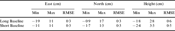
Coordinates estimated from the geodetic receiver sharing the same antenna with the OEM GPS receiver were assumed as known values. The coordinates obtained with the AC12 receiver were compared to the coordinates estimated by the geodetic receiver. The difference between the AC12 and Ashtech Z-Xtreme receivers' solutions are given in Figure 8 for the two baselines respectively. The results including minimum, maximum and root mean square of the error are shown in Table 4.

Figure 8. Comparison of epoch-by-epoch coordinates solutions of OEM and geodetic GPS receivers (Left: Long baseline, Right: Short baseline).
Table 4. Comparison of the results of OEM and geodetic GPS receivers.

It can be seen from Figure 8 and Table 4 that the coordinates estimated by the OEM receiver agree with the known coordinates with a difference of a few centimetres both in position and height components. The maximum deviations of the position component are found −1·9 and −1·7 cm for long and short baselines, respectively. The deviations for the height component reached maximum values of 2·8 and 3·3 cm. This shows that position and height accuracy at the centimetre-level can be obtained for kinematic applications using the low-cost OEM GPS receiver.
CONCLUSIONS
In recent years, the use of OEM GPS receivers in many applications including surveying tasks has been increasing. They are now used as an alternative to the geodetic receiver because of their low-cost properties. In this study, a cost-effective accurate positioning system that utilizes a low-cost OEM GPS receiver that can output carrier phase data is presented and the performance of the system in kinematic mode is analyzed. The results are compared with those produced by a geodetic-grade receiver. Analysis of the results shows that the accuracy of the AC12 GPS receiver-derived coordinates can be obtained with a few centimetre accuracy level using commercial software. On the other hand, a set of zero baseline tests were carried out in order to get an idea of accuracy achievable with AC12 and Ashtech Z-Xtreme GPS receivers. The results of these tests indicate that AC12 receiver has similar noise characteristics as the geodetic receivers. Based on the measurements conducted in this study it can be concluded that an AC12 receiver provides similar results as the geodetic GPS receiver. It is clear that such a level of accuracy can meet the requirement of most kinematic applications. Also, the cost of the equipment used in the field work would be dramatically reduced using such a low-cost OEM GPS receiver.
ACKNOWLEDGEMENTS
This research was funded by ITU Scientific Research Projects Division. The first author would like to gratefully acknowledge the fellowship funding for postdoctoral studies at Ryerson University provided by TUBITAK (The Scientific and Technological Research Council of Turkey) and Dr. A. El-Rabbany for his valuable support during that visit. The authors would like to thank TUBITAK Marmara Research Centre-Earth and Marine Sciences Institute and Bogazici University, for supplying the continuously operating GPS reference stations data. We acknowledge the valuable contributions of A. Sauer from Magellan Professional.