


1. INTRODUCTION
Attitude updating is an essential part of Strapdown Inertial Navigation Systems (SINS), and the corresponding algorithms have been widely used and studied. Examples are rotation vector-based algorithms (Ignagni, Reference Ignagni2012; Kang et al., Reference Kang, Cho and Park2013), the angular rate-based algorithm (Chen and Tang, Reference Chen and Tang2016), the Rodrigues vector iteration-based algorithm (Wu, Reference Wu2018; Wu et al., Reference Wu, Cai and Truong2018) and the Picard iteration-based algorithm (Yan et al., Reference Yan, Weng, Yang and Qin2017). The most popular and widely used algorithm is the rotation vector-based attitude updating algorithm. Miller (Reference Miller1983) first introduced the concept of improving the accuracy of the coning correction by using a coning vibration environment. Ignagni (Reference Ignagni1990) further proved that the coefficients of the algorithms which were optimised under pure coning environments were also optimal under generalised vibrational environments. Then, Ignagni (Reference Ignagni1996) developed a compressed form coning algorithm based on a Taylor series expansion in powers of coning frequency and proved that the uncompressed form was equivalent to the compressed form in pure coning environments. The compressed form assumes that the cross products between time displaced integrated rate samples are a function of time only, while the uncompressed form assumes that all the possible cross products of the integrated angular rate samples are taken into account. The same frequency-series expansion-based method was used later (Jiang and Lin, Reference Jiang and Lin1992; Park et al., Reference Park, Kim, Lee and Chung1999). Savage (Reference Savage2010) presented an approach called Explicit Frequency Shaping (EFS) for coning algorithm design, in which the coefficients were designed by using least-squares error minimisation rather than frequency-series expansion to achieve optimal coning performance. These coning algorithms are optimal over different coning frequency ranges, but they are not optimal under general motion conditions (Song et al., Reference Song, Wu and Pan2013). Song's paper represents a major advancement in coning algorithm design for optimal performance in both high-frequency vibration and low-frequency manoeuvre environments. Although Song's paper considered both high frequency and low frequency coning environments, the triple-cross-product terms of the non-commutativity error were not taken into consideration. Wang et al. (Reference Wang, Wu, Wang and Pan2015) considered the third-order terms of non-commutativity error for coning algorithms design, and the algorithms showed higher accuracy than the traditional algorithms in coning and rotation coexisting environments. Wu (Reference Wu2018) proposed to complete attitude reconstruction using a functional iteration of the Rodrigues vector. The idea was also applied to the approximate three-order rotation vector differential equation, named the RotFIter. The RotFIter showed better performance than the mainstream rotation vector algorithm and it can also provide the attitude result within the whole update time interval, in contrast to traditional algorithms that can only provide attitude at the end of the update time interval. Wu et al. (Reference Wu, Cai and Truong2018) proposed a fast version of RodFIter using a truncated Chebyshev polynomial, which could also be used in principle to speed up the RotFIter.
In contrast to the design process presented in Wang's paper, the two third-order terms of the non-commutativity errors are combined in this paper, and the third-order algorithms are derived analytically based on the third-order Picard component solutions of the rotation vector. Additionally, a fourth-order algorithm is also developed based on the fourth-order Picard component solutions of the rotation vector, which can further improve the rotation vector compensation accuracy under vibratory and manoeuvre environments. The new algorithm can improve the accuracy of high-order coning corrections under manoeuvres and vibration environments. The proposed algorithm can also be used by the post-processing system for high accuracy attitude computation, especially when the output frequency of the gyro is limited due to memory limitations.
This paper is organised as follows: Section 2 shows the Picard components of the rotation vector. The analytical error analysis of the rotation vector is carried out in Section 3. Section 4 demonstrates the design of several high-order correction algorithms for the new rotation vector. The performance of the proposed algorithm is evaluated through different simulation scenarios and high rate manoeuvre roller coaster experiments in Section 5. Finally, the conclusions and the major contributions of this paper are summarised in Section 6. Derivations of the third-order algorithms are presented in Appendix A and derivations for the fourth-order algorithms are shown in Appendix B.
2. PICARD COMPONENTS OF THE ROTATION VECTOR
This section calculates the Picard components of the rotation vector differential equation, which is an efficient method to evaluate and design the new rotation vector algorithms.
The differential equation for rotation vector is given by (Bortz, Reference Bortz1971):
 $$\eqalign{{\dot{\biphi}} &= {\biomega} + \displaystyle{{1}\over{2}} {\biphi} \times {\biomega} + \displaystyle{{1}\over{\phi^{2}}} \left(1 - \displaystyle{{\phi \sin \phi}\over{2\, \lpar 1 - \cos \phi\rpar }}\right){\biphi} \times \lpar {\biphi} \times {\biomega}\rpar \cr &= {\biomega} + \displaystyle{{1}\over{2}} {\biphi} \times {\biomega} + \left(\displaystyle{{1}\over{12}} + \displaystyle{{1}\over{720}}\phi^{2} + \displaystyle{{1}\over{30240}} \phi^4 + \cdots\right){\biphi} \times \lpar {\biphi} \times {\biomega}\rpar } $$
where ϕ is the rotation vector, ϕ is the norm of vector ϕ and ω is the body angular rate vector.
The Picard component solutions to Equation (1) are calculated following Equation (26) of Savage (Reference Savage2006):
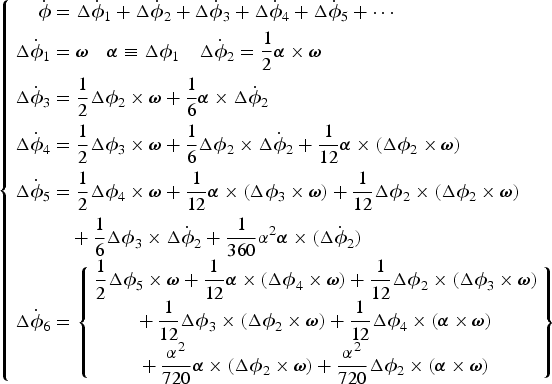 $$\left\{\eqalign{{\dot{\biphi}} &= \Delta {\dot{\biphi}}_{1} + \Delta {\dot{\biphi}}_{2} + \Delta {\dot{\biphi}}_{3} + \Delta {\dot{\biphi}}_{4} + \Delta {\dot{\biphi}}_{5} + \cdots \cr \Delta {\dot{\biphi}}_{1} & = {\biomega} \quad {\bialpha} \equiv \Delta {\biphi}_{1} \quad \Delta {\dot{\biphi}}_{2} = \displaystyle{{1}\over{2}} {\bialpha} \times {\biomega} \cr \Delta {\dot{\biphi}}_{3} &= \displaystyle{{1}\over{2}} \Delta {\biphi}_{2} \times {\biomega} + \displaystyle{{1}\over{6}} {\bialpha} \times \Delta {\dot{\biphi}}_{2} \cr \Delta {\dot{\biphi}}_{4} &= \displaystyle{{1}\over{2}} \Delta {\biphi}_{3} \times {\biomega} + \displaystyle{{1}\over{6}}\Delta {\biphi}_{2} \times \Delta {\dot{\biphi}}_{2} + \displaystyle{{1}\over{12}}{\bialpha} \times \lpar \Delta {\biphi}_{2} \times {\biomega}\rpar \cr \Delta {\dot{\biphi}}_{5} & = \displaystyle{{1}\over{2}}\Delta {\biphi}_{4} \times {\biomega} + \displaystyle{{1}\over{12}}{\bialpha} \times \lpar \Delta {\biphi}_{3} \times {\biomega}\rpar + \displaystyle{{1}\over{12}} \Delta {\biphi}_{2} \times \lpar \Delta {\biphi}_{2} \times {\biomega}\rpar \cr & \quad + \displaystyle{{1}\over{6}}\Delta {\biphi}_{3} \times \Delta {\dot{\biphi}}_{2} + \displaystyle{{1}\over{360}} \alpha^2 {\bialpha} \times \lpar \Delta {\dot{\biphi}}_{2}\rpar \cr \Delta {\dot{\biphi}}_{6}& = \left\{\matrix{ \displaystyle{{1}\over{2}}\Delta {\biphi}_{5} \times {\biomega} + \displaystyle{{1}\over{12}} {\bialpha} \times \lpar \Delta {\biphi}_{4} \times {\biomega}\rpar + \displaystyle{{1}\over{12}} \Delta {\biphi}_{2} \times \lpar \Delta {\biphi}_{3} \times {\biomega}\rpar \cr +\, \displaystyle{{1}\over{12}}\Delta {\biphi}_{3} \times \lpar \Delta {\biphi}_{2} \times {\biomega}\rpar + \displaystyle{{1}\over{12}} \Delta {\biphi}_{4} \times \lpar {\bialpha} \times {\biomega}\rpar \cr +\, \displaystyle{{\alpha^2}\over{720}}{\bialpha} \times \lpar \Delta {\biphi}_{2} \times {\biomega}\rpar + \displaystyle{{\alpha^2}\over{720}} \Delta {\biphi}_{2} \times \lpar {\bialpha} \times {\biomega}\rpar }\right\}}\right. $$
where α is the norm of vector α. The rotation vector is the integral of Equation (2):
 $${\biphi} = \Delta {\biphi}_{1} + \Delta {\biphi}_{2} + \Delta {\biphi}_{3} + \Delta {\biphi}_{4} + \Delta {\biphi}_{5} + \Delta {\biphi}_{6} + \cdots $$
where the Δϕ2, Δϕ3, Δϕ4, Δϕ5, Δϕ6 · · · terms in Equation (3) are called coning corrections to the integrated angular rate α.
Traditional rotation vector algorithms considered only the Δϕ1, Δϕ2 terms, while ignoring the high-order terms Δϕ3, Δϕ4, · · ·. However, in this paper, the higher order terms are also considered to calculate the rotation vector more accurately. Two versions are considered, a third order version ϕThird using Δϕ3 and a fourth order version ϕFourth using both Δϕ3 and Δϕ4. The time derivative of the traditional ϕTrad and two higher order rotation vector versions can be rewritten as:
 $${\dot{\biphi}}_{{Trad}} \equiv \Delta {\dot{\biphi}}_{1} +\Delta {\dot{\biphi}}_{2} ={\biomega} +\Delta {\dot{\biphi}}_{2} $$
 $${\dot{\biphi}}_{{Third}} \equiv \Delta {\dot{\biphi}}_{1} + \Delta {\dot{\biphi}}_{2} + \Delta {\dot{\biphi}}_{3} = {\biomega} + \Delta {\dot{\biphi}}_{2} + \Delta {\dot{\biphi}}_{3} $$
 $${\dot{\biphi}}_{{Fourth}} \equiv \Delta {\dot{\biphi}}_{1} + \Delta {\dot{\biphi}}_{2} + \Delta {\dot{\biphi}}_{3} +\Delta {\dot{\biphi}}_{4} = {\biomega} + \Delta {\dot{\biphi}}_{2} + \Delta {\dot{\biphi}}_{3} + \Delta {\dot{\biphi}}_{4} $$
Integrating Equations (4) – (6) from t n−1 to t, gives the rotation vectors at time t, which can be expressed as:
 $${\biphi}_{{Trad}} \lpar t\rpar = {\bialpha} \lpar t\rpar + \Delta {\biphi}_{2} \lpar t\rpar $$
 $${\biphi}_{{Third}} \lpar t\rpar = {\bialpha} \lpar t\rpar + \Delta {\biphi}_{2} \lpar t\rpar + \Delta {\biphi}_{3} \lpar t\rpar $$
 $${\biphi}_{{Fourth}} \lpar t\rpar = {\bialpha} \lpar t\rpar + \Delta {\biphi}_{2} \lpar t\rpar + \Delta {\biphi}_{3} \lpar t\rpar + \Delta {\biphi}_{4} \lpar t\rpar $$
The Δϕ2(t) second order coning correction term has been used as the design basis for many past coning algorithms (Ignagni, Reference Ignagni1990; Reference Ignagni1996; Reference Ignagni2012; Kang et al., Reference Kang, Cho and Park2013; Miller, Reference Miller1983; Lee et al., Reference Lee, Mark, Tazartes and Yoon1990; Savage, Reference Savage2010; Song et al., Reference Song, Wu and Pan2013). The focus of this section is to derive Δϕ3(t) and Δϕ4(t), the third and fourth order coning corrections. For simplicity, Δϕ3(t) is divided into two parts, which are Δϕ3A(t) and Δϕ3B(t) (Wang et al., Reference Wang, Wu, Wang and Pan2015). Thus, from Equation (2):
 $$\Delta {\biphi}_{3} \lpar t\rpar = \Delta {\biphi}_{3A} \lpar t\rpar + \Delta {\biphi}_{3B} \lpar t\rpar $$
 $$\Delta {\biphi}_{3A} \lpar t\rpar = -\displaystyle{{1}\over{6}} {\bialpha} \lpar t\rpar \times \left[\displaystyle{{1}\over{2}} \vint_{t_{n-1}}^t \lpar {\bialpha} \times {\biomega}\rpar dt\right]$$
 $$\Delta {\biphi}_{3B} \lpar t\rpar = \displaystyle{{1}\over{6}} \vint_{t_{n-1}}^t \left\{\lsqb {\bialpha} \times\rsqb \lpar {\bialpha} \times {\biomega}\rpar - \lsqb {\biomega} \times\rsqb \left(\vint_{t_{n-1}}^t\lpar {\bialpha} \times {\biomega}\rpar dt\right)\right\}dt $$
 $$\Delta {\biphi}_{4} \lpar t\rpar = \vint_{t_{n-1}}^t \displaystyle{{1}\over{2}} \Delta {\biphi}_{3} \times {\biomega} + \displaystyle{{1}\over{6}} \Delta {\biphi}_{2} \times \Delta {\dot{\biphi}}_{2} + \displaystyle{{1}\over{12}} {\bialpha} \times \lpar \Delta {\biphi}_{2} \times {\biomega}\rpar \, dt $$
3. ANALYTICAL ERROR ANALYSIS OF THE ROTATION VECTOR
This section presents error analysis of the traditional second-order rotation vector equation compared with the new third and fourth order rotation vector equations under general angular rate environments. The underlying reason why the accuracy of the traditional rotation vector algorithms cannot be improved is disclosed. For more explanations about why the accuracy of the traditional algorithm is limited, the reader can also refer to Yan et al. (Reference Yan, Yan and Xu2008) and Wu (Reference Wu2018).
From Equation (3), the actual rotation vector value ϕTrue can be described as:
 $${\biphi}_{{True}} = {\bialpha} + \Delta {\biphi}_{2} + \Delta {\biphi}_{3} + \Delta {\biphi}_{4} + \Delta {\biphi}_{5} + \Delta {\biphi}_{6} + \cdots $$
The error between the rotation vector computation algorithms for ϕTrad, ϕThird, ϕFourth and the actual rotation vector ϕTrue can be expressed as:
 $$\eqalign{e\lpar \hat{{\biphi}}_{{Trad}} \rpar \equiv \hat{{\biphi}}_{{Trad}} - {\biphi}_{{True}} \quad e\lpar \hat{{\biphi}}_{{Third}}\rpar \equiv \hat{{\biphi}}_{{Third}} - {\biphi}_{{True}} \quad e\lpar \hat{{\biphi}}_{{Fourth}}\rpar \equiv \hat{{\biphi}}_{{Fourth}} - {\biphi}_{{True}} } $$
where  $\hat{{\biphi}}_{{Trad}}\comma \; \hat{{\biphi}}_{{Third}}\comma \; \hat{{\biphi}}_{{Fourth}}$ are the computation algorithms for ϕTrad, ϕThird, ϕFourth and
  $e\lpar \hat{{\biphi}}_{{Trad}}\rpar $,
  $e\lpar \hat{{\biphi}}_{{Third}}\rpar $,
  $e\lpar \hat{{\biphi}}_{{Fourth}}\rpar $ are the
  $\hat{{\biphi}}_{{Trad}}\comma \; \hat{{\biphi}}_{{Third}}\comma \; \hat{{\biphi}}_{{Fourth}}$ algorithm errors. Similarly, the algorithm errors regarding each Picard components can be defined as:
 $$e\lpar \widehat{\Delta {\biphi}_{2}}\rpar \equiv \widehat{\Delta {\biphi}_{2}} - \Delta {\biphi}_{2} \quad e\lpar \widehat{\Delta {\biphi}_{3}}\rpar \equiv \widehat{\Delta {\biphi}_{3}} - \Delta {\biphi}_{3} \quad e\lpar \widehat{\Delta {\biphi}_{4}}\rpar \equiv \widehat{\Delta {\biphi}_{4}} - \Delta {\biphi}_{4} $$
where  $\widehat{\Delta {\biphi}_{2}}\comma \; \widehat{\Delta {\biphi}_{3}}\comma \; \widehat{\Delta {\biphi}_{4}}$ are the computation algorithms for Δϕ2, Δϕ3, Δϕ4 and
  $e\lpar \widehat{\Delta {\biphi}_{2}}\rpar $,
  $e\lpar \widehat{\Delta {\biphi}_{3}}\rpar $,
  $e\lpar \widehat{\Delta {\biphi}_{4}}\rpar $ are the
  $\widehat{\Delta {\biphi}_{2}}\comma \; \widehat{\Delta {\biphi}_{3}}\comma \; \widehat{\Delta {\biphi}_{4}}$ algorithm errors.
The traditional second order algorithm is based on Equation (3), ignoring the Δϕ3 + Δϕ4 + Δϕ5 + Δϕ6 + · · · terms:
 $$\hat{{\biphi}}_{{Trad}} = {\bialpha} + \widehat{\Delta {\biphi}_{2}} $$
Similarly, the new third order and fourth order algorithms based on Equation (3) are:
 $$\hat{{\biphi}}_{{Third}} = {\bialpha} + \widehat{\Delta {\biphi}_{2}} + \widehat{\Delta {\biphi}_{3}} $$
 $$\hat{{\biphi}}_{{Fourth}} = {\bialpha} + \widehat{\Delta {\biphi}_{2}} + \widehat{\Delta {\biphi}_{3}} + \widehat{\Delta {\biphi}_{4}} $$
Substituting Equations (17) (18), and (19) into the definition of the rotation vector errors, Equations (15) and (16), the rotation vector algorithm errors can be expressed as:
 $$\eqalign{ e\lpar \hat{{\biphi}}_{{Trad}}\rpar &= \hat{{\biphi}}_{{Trad}} - {\biphi}_{{True}} \cr &= {\bialpha} +\widehat{\Delta {\biphi}_{2}} - \left({\bialpha} + \sum \Delta {\biphi}_{i} \right)=e\lpar \widehat{\Delta {\biphi}_{2}}\rpar - \lpar \Delta {\biphi}_{3} + \Delta {\biphi}_{4} + \Delta {\biphi}_{5} + \Delta {\biphi}_{6} + \cdots\rpar } $$
 $$\eqalign{ e\lpar \hat{{\biphi}}_{{Third}} \rpar &= \hat{{\biphi}}_{{Third}} - {\biphi}_{{True}} \cr &= {\bialpha} + \widehat{\Delta {\biphi}_{2}} + \widehat{\Delta {\biphi}_{3}} - \left({\bialpha} + \sum \Delta {\biphi}_{i}\right)= e \lpar \widehat{\Delta {\biphi}_{2}}\rpar \cr &\quad + e\lpar \widehat{\Delta {\biphi}_{3}}\rpar - \lpar \Delta {\biphi}_4 + \Delta {\biphi}_{5} + \Delta {\biphi}_{6} +\cdots\rpar } $$
 $$\eqalign{ e\lpar \hat{{\biphi}}_{{Fourth}}\rpar &= \hat{{\biphi}}_{{Fourth}} - {\biphi}_{{True}} \cr &= {\bialpha} + \widehat{\Delta {\biphi}_{2}} + \widehat{\Delta {\biphi}_{3}} + \widehat{\Delta {\biphi}_{4}} - \left({\bialpha} +\sum \Delta {\biphi}_{i}\right)\cr & =e\lpar \widehat{\Delta {\biphi}_{2}}\rpar +e\lpar \widehat{\Delta {\biphi}_{3}}\rpar +e\lpar \widehat{\Delta {\biphi}_{4}}\rpar - \lpar \Delta {\biphi}_{5} + \Delta {\biphi}_{6} + \cdots\rpar } $$
Similar analytical error analysis with Equation (44) from Savage (Reference Savage2006) is done here, where the manoeuvre profiles are described in Equation (23):
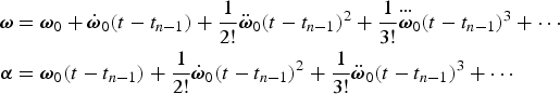 $$\eqalign{{\biomega} & = {\biomega}_0 + \dot{{\biomega}}_0 \lpar t - t_{n-1}\rpar + \displaystyle{{1}\over{2!}} \ddot{{\biomega}}_0 \lpar t - t_{n-1}\rpar ^2 + \displaystyle{{1}\over{3!}} {\mathop{{\biomega}}\limits^{\cdots}}_0 \lpar t - t_{n-1}\rpar ^3 + \cdots \cr {\bialpha} &= {\biomega}_0 \lpar t - t_{n-1}\rpar + \displaystyle{{1}\over{2!}} \dot{{\biomega}}_0 \lpar t - t_{n-1}\rpar ^2 + \displaystyle{{1}\over{3!}}\ddot{{\biomega}}_0 \lpar t - t_{n-1}\rpar ^3 + \cdots} $$
where ω0 represents the value of ω at t n−1,  $\dot{{\biomega}}_{0}$ represents the value of the first-order derivative of ω at t n−1 and
  $\ddot{{\biomega}}_{0}$ represents the value of the second-order derivative of ω at t n−1, etc. The Δϕ3, Δϕ4, Δϕ5 and Δϕ6 values are calculated (from t n−1 to t) by substituting Equation (23) into Equation (2):
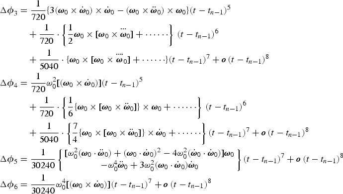 $$\eqalign{ \Delta {\biphi}_{3} &= \displaystyle{{1}\over{720}} \lcub 3\lpar {\biomega}_0 \times \dot{{\biomega}}_0\rpar \times \dot{{\biomega}}_0 - \lpar {\biomega}_0 \times \ddot{{\biomega}}_0\rpar \times {\biomega}_0\rcub \lpar t - t_{n-1}\rpar ^5 \cr &\quad + \displaystyle{{1}\over{720}} \cdot \left\{\displaystyle{{1}\over{2}} {\biomega}_0 \times \lsqb {\biomega}_0 \times {\mathop{{\biomega}}\limits^{\cdots}}_0\rsqb + \cdots \cdots\right\}\, \lpar t - t_{n-1}\rpar ^6 \cr &\quad + \displaystyle{{1}\over{5040}} \cdot \lcub {\biomega}_0 \times \lsqb {\biomega}_0 \times {\mathop{{\biomega}}\limits^{\cdots \cdot}}_0\rsqb + \cdots \cdots\rcub \lpar t - t_{n-1}\rpar ^7 + {\bi o}\, \lpar t - t_{n-1}\rpar ^8 \cr \Delta {\biphi}_{4} &= \displaystyle{{1}\over{720}} \omega_0^2 \lsqb \lpar {\biomega}_0 \times \dot{{\biomega}}_0\rpar \rsqb \lpar t - t_{n-1}\rpar ^5 \cr &\quad + \displaystyle{{1}\over{720}} \cdot \left\{\displaystyle{{1}\over{6}} \lcub {\biomega}_0 \times \lsqb {\biomega}_0 \times \ddot{{\biomega}}_0\rsqb \rcub \times {\biomega}_0 + \cdots \cdots\right\}\, \lpar t - t_{n-1}\rpar ^6 \cr &\quad + \displaystyle{{1}\over{5040}} \cdot \left\{\displaystyle{{7}\over{4}} \lcub {\biomega}_0 \times \lsqb {\biomega}_0 \times \ddot{{\biomega}}_0\rsqb \rcub \times \dot{{\biomega}}_0 + \cdots \cdots\right\}\lpar t - t_{n-1}\rpar ^7 + {\bi o}\, \lpar t-t_{n-1}\rpar ^8 \cr \Delta {\biphi}_{5} &= \displaystyle{{1}\over{30240}} \left\{\matrix{ \lsqb \omega_0^2 \lpar {\biomega}_0 \cdot \ddot{{\biomega}}_0\rpar + \lpar {\biomega}_0 \cdot \dot{{\biomega}}_0\rpar^2 - 4\omega_0^2 \lpar \dot{{\biomega}}_0 \cdot \dot{{\biomega}}_0\rpar \rsqb {\biomega}_0 \cr -\omega_0^4 \ddot{{\biomega}}_0 + 3\omega_0^2 \lpar {\biomega}_0 \cdot \dot{{\biomega}}_0\rpar \dot{{\biomega}}_0 }\right\}\lpar t - t_{n-1}\rpar ^7 + {\bi o}\, \lpar t - t_{n-1}\rpar ^8 \cr \Delta {\biphi}_{6} &= \displaystyle{{1}\over{30240}} \omega_0^4 \lsqb \lpar {\biomega}_0 \times \dot{{\biomega}}_0\rpar \rsqb \lpar t - t_{n-1}\rpar ^7 + {\bi o}\, \lpar t - t_{n-1}\rpar ^8} $$
Then, the error of the traditional algorithm Equation (20) becomes:
 $$\eqalign{ e\lpar \hat{{\biphi}}_{{Trad}}\rpar &= e\lpar \widehat{\Delta {\biphi}_{2}}\rpar - \lpar \Delta {\biphi}_{3} + \Delta {\biphi}_{4} + \Delta {\biphi}_{5} + \Delta {\biphi}_{6} + \cdots\rpar \cr &= e\lpar \widehat{\Delta {\biphi}_{2}}\rpar + {\bi o}\, \lpar t - t_{n-1}\rpar ^8 \cr &\quad - \displaystyle{{1}\over{720}} \lcub 3\lpar {\biomega}_0 \times \dot{{\biomega}}_0\rpar \times \dot{{\biomega}}_0 - \lpar {\biomega}_0 \times \ddot{{\biomega}}_0\rpar \times {\biomega}_0 + \omega_0^2 \lpar {\biomega}_0 \times \dot{{\biomega}}_0\rpar \rcub \lpar t - t_{n - 1}\rpar ^5 \cr &\quad - \displaystyle{{1}\over{720}} \cdot \left\{\displaystyle{{1}\over{2}} {\biomega}_0 \times \lsqb {\biomega}_0 \times {\mathop{{\biomega}}\limits^{\cdots \cdot}}_0\rsqb + \cdots \cdots\right\}\, \lpar t - t_{n-1}\rpar ^6 \cr &\quad - \displaystyle{{1}\over{5040}} \lcub {\biomega}_0 \times \lsqb {\biomega}_0 \times {\mathop{{\biomega}}\limits^{\cdots \cdot}}_0\rsqb + \cdots \cdots\rcub \lpar t - t_{n-1}\rpar ^7} $$
Similarly, the errors of the higher-order algorithms, Equations (21) and (22), become:
 $$\eqalign{ e\lpar \hat{{\biphi}}_{{Third}}\rpar &= e\lpar \widehat{\Delta {\biphi}_{2}}\rpar + e\lpar \widehat{\Delta {\biphi}_{3}}\rpar + {\bi o}\, \lpar t - t_{n-1}\rpar ^8 \cr &\quad - \displaystyle{{1}\over{720}} \lcub \omega_0^2 \lsqb \lpar {\biomega}_0 \times \dot{{\biomega}}_0\rpar \rsqb \rcub \lpar t - t_{n-1}\rpar ^5 \cr &\quad -\displaystyle{{1}\over{720}} \cdot \left\{\displaystyle{{1}\over{6}} \lcub {\biomega}_0 \times \lsqb {\biomega}_0 \times \ddot{{\biomega}}_0\rsqb \rcub \times {\biomega}_0 + \cdots \cdots\right\}\, \lpar t - t_{n-1}\rpar ^6 \cr &\quad - \displaystyle{{1}\over{5040}} \left\{\displaystyle{{7}\over{4}}\lpar {\biomega}_0 \times \lsqb {\biomega}_0 \times \ddot{{\biomega}}_0\rsqb \rpar \times \dot{{\biomega}}_0 + \cdots \cdots\right\}\lpar t - t_{n-1}\rpar ^7} $$
 $$\eqalign{ e\lpar \hat{{\biphi}}_{{Fourth}}\rpar &= e\lpar \widehat{\Delta {\biphi}_{2}}\rpar + e\lpar \widehat{\Delta {\biphi}_{3}}\rpar + e\lpar \widehat{\Delta {\biphi}_{4}}\rpar + {\bi o}\, \lpar t - t_{n-1}\rpar ^8 \cr &\quad - \displaystyle{{1}\over{30240}} \left\{\matrix{ \lsqb \omega_0^2 \lpar {\biomega}_0 \cdot \ddot{{\biomega}}_0\rpar + \lpar {\biomega}_0 \cdot \dot{{\biomega}}_0\rpar^2 - 4\omega_0^2 \lpar \dot{{\biomega}}_0 \cdot \dot{{\biomega}}_0\rpar \rsqb {\biomega}_0 \cr -\omega_0^4 \ddot{{\biomega}}_0 + 3\omega_0^2 \lpar {\biomega}_0 \cdot \dot{{\biomega}}_0\rpar \dot{{\biomega}}_0 + \omega_0^4 \lpar {\biomega}_0 \times \dot{{\biomega}}_0\rpar }\right\}\lpar t - t_{n-1}\rpar ^7} $$
 Equation (25) reveals that a  $\hat{{\biphi}}_{{Trad}}$ traditional second-order rotation vector algorithm has fourth-order accuracy (the comment below Equation (42) in Savage (Reference Savage2006)), limited by the (t − t n−1)5 level error in Δϕ3 and Δϕ4. As well as that, the (t − t n−1)5 level error is not a small value when the platform works in a manoeuvring environment or when the gyro samples have limited output frequency. For example, the error
  $e\lpar \widehat{\Delta {\biphi}_{2}}\rpar $ of the uncompressed four-sample algorithm (Song et al., Reference Song, Wu and Pan2013) is of the (t − t n−1)7 level, which is two levels smaller than (t − t n−1)5. As a result, the accuracy of
  $\hat{{\biphi}}_{{Trad}}$ cannot be improved by merely increasing the number of gyro samples.
Equations (25) and (26) show that the third-order rotation vector algorithm eliminates the  $\lcub 3\lpar {\biomega}_{0} \times \dot{{\biomega}}_{0}\rpar \times \dot{{\biomega}}_{0} - \lpar {\biomega}_{0} \times \ddot{{\biomega}}_{0}\rpar \times {\biomega}_{0}\rcub \lpar t - t_{n-1}\rpar ^{5}/720$ error term in
  $\hat{{\biphi}}_{{Trad}}$. However, the fifth order
  $\lcub \omega_{0}^{2} \lsqb \lpar {\biomega}_{0} \times \dot{{\biomega}}_{0}\rpar \rsqb \rcub \lpar t - t_{n-1}\rpar ^{5}/720$ error term remains, in addition to the
  $e \lpar \widehat{\Delta {\biphi}_{2}}\rpar + e\lpar \widehat{\Delta {\biphi}_{3}}\rpar $ error terms in the
  $\widehat{\Delta {\biphi}_{2}}$,
  $\widehat{\Delta {\biphi}_{3}}$ coning algorithms. Equation (27) shows that a
  $\hat{{\biphi}}_{{Fourth}}$ fourth order rotation vector, has (t − t n−1)7 errors, in addition to the
  $e\lpar \widehat{\Delta {\biphi}_{2}}\rpar + e\lpar \widehat{\Delta {\biphi}_{3}}\rpar + e\lpar \widehat{\Delta {\biphi}_{4}}\rpar $ error terms in the
  $\widehat{\Delta {\biphi}_{2}}$,
  $\widehat{\Delta {\biphi}_{3}}$,
  $\widehat{\Delta {\biphi}_{4}}$ coning algorithms.
The previous discussion shows that the error of the third order rotation vector algorithm and the traditional second order algorithm are of the same order, in terms of the power of (t − t n−1); thus, a fourth order algorithm is required to achieve higher accuracy. The remainder of this paper will focus on the design and the evaluation of the fourth-order rotation vector algorithms,  $\hat{{\biphi}}_{{Fourth}}$ defined in Equation (19), so that the
  $e \lpar \widehat{\Delta {\biphi}_{3}}\rpar + e\lpar \widehat{\Delta {\biphi}_{4}}\rpar $ errors in Equation (27) are smaller than the (t − t n−1)5 errors in Equation (25) for
  $\hat{{\biphi}}_{{Trad}}$.
4. CONING ALGORITHMS FOR THE FOURTH ORDER ROTATION VECTOR
The  $\widehat{\Delta {\biphi}_{2}}$ second-order coning algorithm in Equation (19) uses the uncompressed four-sample algorithm in Song et al. (Reference Song, Wu and Pan2013) to achieve high accuracy. The
  $\widehat{\Delta {\biphi}_{3}}$ third-order coning algorithm in Equation (19) is directly given in Equation (28); more details can be found in Appendix A.
 $$\eqalign{ \widehat{\Delta {\biphi}_{3}} &= \sum_{k = N - L_{mn} + 1}^N \sum_{i = 1}^{N - 1} \sum_{j = i + 1}^N \left(-\displaystyle{{1}\over{6}} \varsigma_{ij}\right)\lsqb \Delta {\bialpha}_{Tm\comma k} \times \lpar \Delta {\bialpha}_{Tm\comma i} \times \Delta {\bialpha}_{Tm\comma j}\rpar \rsqb \cr &\quad + \sum_{k=1}^N \sum_{i=1}^{N-1} \sum_{j = i+ 1 }^N \xi_{kij} \lsqb \Delta {\bialpha}_{Tm\comma k} \times \lpar \Delta {\bialpha}_{Tm\comma i} \times \Delta {\bialpha}_{Tm\comma j}\rpar \rsqb } $$
with  $\varsigma_{ij}$ and ξkij defined in Appendix A. The
  $\widehat{\Delta {\biphi}_{4}}$ fourth order coning algorithm in Equation (19) is directly given in Equation (29); more details can be found in Appendix B.
 $$\widehat{\Delta {\biphi}_{4}} = \sum_{w=1}^N \sum_{k=1}^N \sum_{i=1}^{N-1} \sum_{j=i+1}^N \upsilon_{wkij} \lsqb \Delta {\bialpha}_{Tm\comma w} \times \lpar \Delta {\bialpha}_{Tm\comma k} \times \lpar \Delta {\bialpha}_{Tm\comma i} \times \Delta {\bialpha}_{Tm\comma j}\rpar \rpar \rsqb $$
with υwkij defined in Appendix B.
4.1. Four-sample second-order coning algorithm
The four-sample second-order coning algorithm  $\widehat{\Delta {\biphi}_{2}}$ uses the uncompressed form algorithm in Song et al. (Reference Song, Wu and Pan2013):
 $$\eqalign{\widehat{\Delta {\biphi}_{2}}_{-UncFSr4} &= \displaystyle{{232}\over{315}}\lpar \Delta {\bialpha}_{Tm\comma 3} \times \Delta {\bialpha}_{Tm\comma 4}\rpar + \displaystyle{{46}\over{105}} \lpar \Delta {\bialpha}_{Tm\comma 2} \times \Delta {\bialpha}_{Tm\comma 4}\rpar + \displaystyle{{18}\over{35}}\lpar \Delta {\bialpha}_{Tm\comma 1} \times \Delta {\bialpha}_{Tm\comma 4}\rpar \cr &\quad + \displaystyle{{178}\over{315}}\lpar \Delta {\bialpha}_{Tm\comma 2} \times \Delta {\bialpha}_{Tm\comma 3}\rpar + \displaystyle{{46}\over{105}}\lpar \Delta {\bialpha}_{Tm\comma 1} \times \Delta {\bialpha}_{Tm\comma 3}\rpar \cr &\quad + \displaystyle{{232}\over{315}}\lpar \Delta {\bialpha}_{Tm\comma 1} \times \Delta {\bialpha}_{Tm\comma 2}\rpar } $$
4.2. Four-sample third-order coning algorithm
The four-sample third-order coning algorithm is named TSrH44. It is calculated using four gyro samples, N = 4 and L mn = 4 (four sequential ΔαTm samples for calculation, which are in the current updating cycle).  $\widehat{\Delta {\biphi}_{3}}_{-TSrH44}$ is expressed by Equation (28) as:
 $$\widehat{\Delta {\biphi}_{3}}_{-TSrH44} = \left\{\matrix{ \left(-\displaystyle{{489}\over{1459}}\Delta {\bialpha}_{Tm\comma 4} - \displaystyle{{694}\over{1573}} \Delta {\bialpha}_{Tm\comma 3} - \displaystyle{{753}\over{3056}}\Delta {\bialpha}_{Tm\comma 2} + \displaystyle{{591}\over{5179}} \Delta {\bialpha}_{Tm\comma 1}\right)\cr \times \lpar \Delta {\bialpha}_{Tm\comma 1} \times \Delta {\bialpha}_{Tm\comma 2}\rpar \cr + \left(-\displaystyle{{171}\over{662}} \Delta {\bialpha}_{Tm\comma 4} - \displaystyle{{109}\over{3719}} \Delta {\bialpha}_{Tm\comma 3} + \displaystyle{{157}\over{695}} \Delta {\bialpha}_{Tm\comma 2} + \displaystyle{{265}\over{3934}} \Delta {\bialpha}_{Tm\comma 1}\right)\cr \times \lpar \Delta {\bialpha}_{Tm\comma 1} \times \Delta {\bialpha}_{Tm\comma 3}\rpar \cr + \left(-\displaystyle{{156}\over{1571}}\Delta {\bialpha}_{Tm\comma 4} + \displaystyle{{249}\over{1441}} \Delta {\bialpha}_{Tm\comma 3} + \displaystyle{{455}\over{23834}} \Delta {\bialpha}_{Tm\comma 2} + \displaystyle{{156}\over{1571}} \Delta {\bialpha}_{Tm\comma 1}\right)\cr \times \lpar \Delta {\bialpha}_{Tm\comma 1} \times \Delta {\bialpha}_{Tm\comma 4}\rpar \cr + \left(-\displaystyle{{113}\over{235}}\Delta {\bialpha}_{Tm\comma 4} - \displaystyle{{111}\over{823}} \Delta {\bialpha}_{Tm\comma 3} + \displaystyle{{111}\over{823}}\Delta {\bialpha}_{Tm\comma 2} + \displaystyle{{206}\over{1901}} \Delta {\bialpha}_{Tm\comma 1}\right)\cr \times \lpar \Delta {\bialpha}_{Tm\comma 2} \times \Delta {\bialpha}_{Tm\comma 3}\rpar \cr + \left(-\displaystyle{{265}\over{3934}}\Delta {\bialpha}_{Tm\comma 4} + \displaystyle{{247}\over{1685}}\Delta {\bialpha}_{Tm\comma 3} + \displaystyle{{109}\over{3719}}\Delta {\bialpha}_{Tm\comma 2} + \displaystyle{{1549}\over{23321}}\Delta {\bialpha}_{Tm\comma 1}\right)\cr \times \lpar \Delta {\bialpha}_{Tm\comma 2} \times \Delta {\bialpha}_{Tm\comma 4}\rpar \cr + \left(-\displaystyle{{591}\over{5179}}\Delta {\bialpha}_{Tm\comma 4} + \displaystyle{{753}\over{3056}} \Delta {\bialpha}_{Tm\comma 3} + \displaystyle{{175}\over{2547}}\Delta {\bialpha}_{Tm\comma 2} + \displaystyle{{491}\over{3427}} \Delta {\bialpha}_{Tm\comma 1}\right)\cr \times \lpar \Delta {\bialpha}_{Tm\comma 3} \times \Delta {\bialpha}_{Tm\comma 4}\rpar }\right\}$$
4.3. Four-sample fourth-order coning algorithm
The four-sample fourth-order algorithm is calculated using four gyro samples, N = 4 and L mn = 4. It is named TSrG44.  $\widehat{\Delta {\biphi}_{4}}_{-TSrG44}$ is expressed by Equation (29) as:
 $$\eqalign{ \widehat{\Delta {\biphi}_{4}}_{-TSrG44} &= A_{12} \lpar \Delta {\bialpha}_{Tm\comma 1} \times \Delta {\bialpha}_{Tm\comma 2}\rpar + A_{13} \lpar \Delta {\bialpha}_{Tm\comma 1} \times \Delta {\bialpha}_{Tm\comma 3}\rpar + A_{14} \lpar \Delta {\bialpha}_{Tm\comma 1} \times \Delta {\bialpha}_{Tm\comma 4}\rpar \cr &\quad + A_{23} \lpar \Delta {\bialpha}_{Tm\comma 2} \times \Delta {\bialpha}_{Tm\comma 3}\rpar + A_{24} \lpar \Delta {\bialpha}_{Tm\comma 2} \times \Delta {\bialpha}_{Tm\comma 4}\rpar + A_{34} \lpar \Delta {\bialpha}_{Tm\comma 3} \times \Delta {\bialpha}_{Tm\comma 4}\rpar } $$
where the A 12, A 13, A 14, A 23, A 24 and A 34 are expressed in a similar form as A 12 in Equation (33):
 $$A_{12} = \left[\matrix{ a_{12-1} \lpar \Delta {\bialpha}_{Tm\comma 1} \cdot \Delta {\bialpha}_{Tm\comma 1}\rpar + a_{12-2} \lpar \Delta {\bialpha}_{Tm\comma 2} \cdot \Delta {\bialpha}_{Tm\comma 2}\rpar \cr \quad + \, a_{12-3} \lpar \Delta {\bialpha}_{Tm\comma 3} \cdot \Delta {\bialpha}_{Tm\comma 3} \rpar + a_{12-4} \lpar \Delta {\bialpha}_{Tm\comma 4} \cdot \Delta {\bialpha}_{Tm\comma 4}\rpar \cr \quad +\, a_{12-5} \lpar \Delta {\bialpha}_{Tm\comma 1} \cdot \Delta {\bialpha}_{Tm\comma 2}\rpar + a_{12-6} \lpar \Delta {\bialpha}_{Tm\comma 1} \cdot \Delta {\bialpha}_{Tm\comma 3}\rpar \cr \quad +\, a_{12-7} \lpar \Delta {\bialpha}_{Tm\comma 1} \cdot \Delta {\bialpha}_{Tm\comma 4}\rpar + a_{12-8} \lpar \Delta {\bialpha}_{Tm\comma 2} \cdot \Delta {\bialpha}_{Tm\comma 3}\rpar \cr \quad +\, a_{12-9} \lpar \Delta {\bialpha}_{Tm\comma 2} \cdot \Delta {\bialpha}_{Tm\comma 4}\rpar + a_{12-10} \lpar \Delta {\bialpha}_{Tm\comma 3} \cdot \Delta {\bialpha}_{Tm\comma 4}\rpar }\right]$$
The a 12−1 in Equation (33) denotes the first coefficient of the double-cross-product term (ΔαTm,1 × ΔαTm,2), and a 12−2 is the second coefficient, etc. Similarly, all the coefficients in Equation (32) are displayed in Table 1.
Table 1. Coefficients of the  ${\widehat{\Delta {\biphi}_{4}}}_{-TSrG44}$ algorithm.

It can be seen from Equations (31) and (32) that the new algorithm Fourth44 only added 60 dot-products, some additions and subtractions, while the cross-products are the same as in Equation (30), so the computational complexity is not a problem.
5. ALGORITHM PERFORMANCE EVALUATIONS
This section demonstrates the accuracy of the proposed four-sample fourth-order rotation vector algorithm under dynamic conditions compared with previous second-order algorithms. The open sourced RodFIter algorithm is also considered for comparison since it has superior performance to the RotFIter algorithm (Wu, Reference Wu2018). The first situation is a pure coning environment with a large half cone angle. The second situation is an outdoor roller coaster manoeuvre experiment.
Symbols used for the simulations are as follows:
1) t indicates the simulation time.
2) TradFSr3 denotes the traditional second-order coning correction algorithm Equation (17), with
 $\widehat{\Delta {\biphi}_{2}}$ using the compressed three-sample coning algorithm.
3) TradFSr4 denotes the traditional second-order coning correction algorithm Equation (17), with
$\widehat{\Delta {\biphi}_{2}}$ using the compressed four-sample coning algorithm.4) TradUncFSr3 denotes the traditional second-order coning correction algorithm Equation (17), with
$\widehat{\Delta {\biphi}_{2}}$ using the uncompressed three-sample coning algorithm.5) TradUncFSr4 denotes the traditional second-order coning correction algorithm Equation (17), with
$\widehat{\Delta {\biphi}_{2}}$ using the uncompressed four-sample coning algorithm.6) Fourth44 denotes the new four-sample fourth-order coning correction algorithm Equation (19), with
$\widehat{\Delta {\biphi}_{2}}$ using the uncompressed four-sample coning algorithm, $\widehat{\Delta {\biphi}_{3}}$ using the four-sample third-order coning algorithm Equation (31), $\widehat{\Delta {\biphi}_{4}}$ using the four-sample fourth-order coning algorithm Equation (32).


5.1. Performance under pure coning vibration environments
This section discusses the performance of the proposed algorithm in a pure coning environment, which has been used for testing by many researchers. The attitude quaternion of the pure coning environment is defined as (Wang et al., Reference Wang, Wu, Wang and Pan2015; Reference Wang, Wu and He2018):
 $$Q\lpar t\rpar = \left[\matrix{ \cos \left(\displaystyle{{a}\over{2}}\right)&\sin \left(\displaystyle{{a}\over{2}}\right)\cos \lpar \Omega t + \Phi_0\rpar &\sin \left(\displaystyle{{a}\over{2}}\right)\sin \lpar \Omega t + \Phi_0\rpar &0 }\right]^T $$
The angular rate ω (t) in body coordinates can be expressed according to Equation (34) (Miller, Reference Miller1983; Ignagni, Reference Ignagni1990; Reference Ignagni1996; Jiang and Lin, Reference Jiang and Lin1992):
 $${\biomega} \lpar t\rpar = \left[\matrix{ -\sin a\cdot \Omega \sin \lpar \Omega t + \Phi_0\rpar &\sin a\cdot \Omega \cos \lpar \Omega t + \Phi_0\rpar &\lpar \Omega \cdot \cos a - \Omega\rpar }\right]^T $$
The advantage of using the derived angular rate in Equation (35) to test the performance of the algorithm is that Equation (34) can provide a closed form attitude quaternion for attitude error comparison. All the algorithms use 100 Hz gyro increments as inputs. The initial phase Φ0 is set to π/2. Attitude error is computed according to Wu (Reference Wu2018). Figure 1 shows the attitude errors when Ω = 10π rad/s and a = 2°. Figure 2 shows the attitude errors when Ω = 0 · 74π rad/s and a = 10°. The number of samples and iteration times used in the RodFIter algorithm are eight and six, respectively.

Figure 1. Attitude errors comparison when a = 2°, Ω = 10π rad/s.

Figure 2. Attitude errors comparison when a = 10°, Ω = 0·74π rad/s.
Figures 1 and 2 show that the uncompressed algorithms TradUncFSr3 and TradUncFSr4 have higher accuracy than the compressed algorithms TradFSr3 and TradFSr4, respectively. This is because the compressed algorithms and the uncompressed algorithms only have the same accuracy in terms of the constant bias compensation under pure coning environments (Song et al., Reference Song, Wu and Pan2013). However, the uncompressed algorithms are designed under general angular rate environments, thus they can also compensate part of the periodical errors in coning environments. However, TradUncFSr3 and TradUncFSr4 still have large periodical errors. The four-sample algorithm TradUncFSr4 performs even worse than the three-sample algorithm TradUncFSr3 as can be seen in Figures 1 and 2. This phenomenon was also identified in Yan et al. (Reference Yan, Yan and Xu2008; Reference Yan, Weng, Yang and Qin2017) and Wu (Reference Wu2018), and the accuracy of attitude updating cannot be improved by simply using the multi-samples algorithms. The reason is that there is also a large error in the rotation vector calculation which has not been considered by previous algorithms, as explained in Section 3. However, the proposed fourth-order algorithm Fourth44 displays superior performance to TradUncFSr3 and TradUncFSr4 and the maximum accuracy improvement reaches three orders of magnitude. The comparison between Fourth44 and RodFIter shows that RodFIter is not always superior to Fourth44 under different coning situations. For more comparisons with different number of samples and iteration times refer to the RodFIter application: https://www.researchgate.net/project/Motion-Representation-and-Inertial-Computation-Inertial-Navigation-and-Beyond.
5.2. Performance under roller coaster manoeuvres
This section reports on manoeuvring experiments using an outdoor roller coaster. Three gyros and three accelerometers were mounted in the Inertial Measurement Unit (IMU). The sampling rate of the Inertial Measurement Unit (IMU) was 4,000 Hz. The ring laser gyro used has constant bias less than 0 · 003°/h, and gyro scale factor less than 1 part per million (ppm). A demonstration figure of the roller coaster experimental platform is shown in Figure 3. The body frame is represented using o-xyz, while the navigation frame is represented by the O-East-North-Up (ENU) local geographic coordinate frame. The roller coaster started from a static state, then underwent a high rate manoeuvre period, and finally ran back to the start point.

Figure 3. Setup of the roller coaster experiment.
The angular rate during the manoeuvre is shown in Figure 4.

Figure 4. Angular rates of the roller coaster manoeuvre.
The 3D trajectory during the roller coaster manoeuvre period is shown in Figure 5.

Figure 5. Trajectory of the roller coaster manoeuvre.
The 4,000 Hz data is summed down to 1,000 Hz as the input of the attitude algorithms. The reference attitude was calculated by processing the 4,000 Hz original data using the RodFIter algorithm, which is accurate enough for algorithm comparison. Attitude error results are shown in Figure 6.

Figure 6. Attitude error comparison under roller coaster manoeuvre.
The uncompressed algorithms TradUncFSr3 and TradUncFSr4 in Figure 5 have higher accuracy than the compressed algorithms TradFSr3 and TradFSr4, respectively. This is because the uncompressed algorithms have expanded the performance of the compressed algorithms, and they also have superior performance in manoeuvre environments. The attitude errors of the uncompressed algorithms TradUncFSr3 and TradUncFSr4 rapidly reach large values when the roller coaster starts to manoeuvre. The multi-samples algorithm TradUncFSr4 does not perform at a higher accuracy than the fewer-samples algorithm TradUncFSr3. The accuracy of the conventional rotation vector algorithms cannot be improved by simply increasing the number of samples for calculation when the platform operates during manoeuvres. However, the new four-sample fourth-order algorithm Fourth44 and the RodFIter algorithm have the best accuracy compared with the other four algorithms; the accuracy has been improved more than one order of magnitude. Fourth44 and RodFIter have nearly the same accuracy in the roller coaster experiment.
The simulation results shown in Figures 1, 2 and 6 have demonstrated the main reasons that limit the accuracy of the traditional compressed or uncompressed algorithms is that large errors lie in Δϕ3 and Δϕ4 and have not been considered by previous algorithms. However, the new algorithm Fourth44 can overcome the limitations of the traditional algorithms, which is useful to manoeuvring or vibrating platforms.
6. CONCLUSIONS
This paper derives the third-, fourth-, fifth- and sixth-order Picard component solutions of the rotation vector differential equation. Theoretical error analysis of the rotation vector under a general angular rate environment has been carried out. The reason that limits the accuracy of the conventional rotation vector-based attitude updating algorithm is discussed. A higher-order rotation vector-based attitude updating algorithm design methodology is proposed, in which the third- and fourth-order Picard component solutions of the rotation vector differential equation are used. The proposed algorithm can be used for enhancing the accuracy for previously designed second-order coning algorithms especially in vibrating and manoeuvring environments. Pure coning vibration with large half cone angle experiments and a roller coaster high rate manoeuvre experiment have validated the high accuracy of the proposed algorithm. The developed algorithms are also applicable to high accuracy post-processing systems.
ACKNOWLEDGEMENTS
This work was supported by the National Natural Science Foundation of China (No. 61573371, No. 61803381), National University of Defense Technology Advanced Research Programs (No. JC14-03-04) and Hunan Project on Science and Technology in China (No. 2017RS3045).
APPENDIX A: THE THIRD-ORDER ALGORITHMS BASED ON TIME TAYLOR SERIES EXPANSION
This appendix shows the derivations of the third-order algorithms  $\widehat{\Delta {\biphi}_{3}}$, while the derivations for the fourth-order algorithms
  $\widehat{\Delta {\biphi}_{4}}$ are shown in Appendix B. The derivations follow the same methodology outlined in Appendix A in Savage (Reference Savage2010), which was used for designing the second-order coning algorithms
  $\widehat{\Delta {\biphi}_{2}}$.
For an N-th order Taylor series, the angular rate is expressed as:
 $$\eqalign{{\biomega}\lpar t\rpar &= {\biomega}\lpar t_0\rpar + \sum_{i=2}^N \displaystyle{{d^{i-1}}\over{dt^{i-1}}} {\biomega}\lpar t\rpar _{t = t_0} \displaystyle{{1}\over{\lpar i-1\rpar !}} \lpar t - t_0\rpar ^{i-1} \cr {\biomega}\lpar \tau\rpar &= {\biomega}\lpar \tau = 0\rpar + \sum_{i=2}^N \displaystyle{{d^{i-1}}\over{d\tau^{i-1}}} {\biomega}\lpar \tau\rpar _{\tau = 0} \displaystyle{{1}\over{\lpar i - 1\rpar !}} \tau^{i-1} } \quad \tau \equiv t - t_0$$
To simplify the notation, the following convention of the time subscript is adopted:
 $$\matrix{t_{n - 1\comma 2L_{mn} - N}&\comma \; & t_{n-1\comma 2L_{mn} - N + 1}&\comma \; \cdots&\comma \; & t_{n-1\comma L_{mn}} = t_{n\comma 0}&\comma \; & t_{n\comma 1}&\comma \; \cdots&\comma \; & t_{n\comma L_{mn}} \cr t_0&\comma \; & t_1&\comma \; \cdots&\comma \; & t_{N-L_{mn}}&\comma \; & t_{N - L_{mn} + 1}&\comma \; \cdots&\comma \; & t_N}$$
where t 0 is the start time of the first gyro sample,  $t_{n-1\comma 2L_{mn} - N}$,
  $t_{n-1\comma 2L_{mn} - N + 1}\comma \; \cdots\comma \; t_{n - 1\comma L_{mn}}$ represent the time in last cycle n − 1, while t n, 0, t n, 1, ···,
  $t_{n\comma L_{mn}}$ represent the time in current cycle n.
The equivalent definition of the angular rate is:
 $${\biomega}\lpar \tau\rpar = \sum_{i=1}^N {\bi b}_i \tau^{i-1} \quad {\bi b}_i = \displaystyle{{d^{i - 1}}\over{d\tau^{i - 1}}} {\biomega}\lpar \tau\rpar _{\tau = 0} \displaystyle{{1}\over{\lpar i - 1\rpar !}} \quad {\bi b}_1 = {\biomega}\lpar \tau = 0\rpar$$
The j-th integrated angular-rate sample for algorithm input is calculated as:
 $$\eqalign{\Delta {\bialpha}_{Tm\comma j} &= \vint_{\lpar j-1\rpar T_m}^{jT_m} {\biomega}\lpar \tau\rpar d\tau\comma \; j = 1\comma \; 2\comma \; \ldots N \cr \Delta {\bialpha}_{Tm\comma j} &= \vint_{\lpar j-1\rpar T_m}^{jT_m} \left(\sum_{i=1}^N {\bi b}_i \tau^{i-1}\right)d\tau\comma \; \quad j = 1\comma \; 2\comma \; \ldots N \cr \Delta {\bialpha}_{Tm\comma j} &= \sum_{i=1}^N \left[\left(\vint_{\lpar j-1\rpar T_m}^{jT_m} \tau^{i-1} d\tau\right){\bi b}_i\right]= \sum_{i=1}^N \left\{\displaystyle{{1}\over{i}} \lsqb \lpar jT_m\rpar^i - \lpar \lpar j - 1\rpar T_m\rpar^i\rsqb {\bi b}_i\right\}}$$
The equivalent form of Equation (A3) can be written as:
 $$\Delta {\bialpha}_{Tm\comma j} = \sum_{i=1}^N \lambda_{ji} {\bi b}_i \quad \lambda_{ji} \equiv \displaystyle{{1}\over{i}} \lsqb \lpar jT_m\rpar^i - \lpar \lpar j-1\rpar T_m\rpar^i\rsqb$$
The transpose of Equation (A4) is:
 $$\Delta {\bialpha}_{Tm\comma j}^T = \sum_{i=1}^N \lambda_{ji} {\bi b}_i^T $$
 $$\Delta A = \left[\matrix{ \Delta {\bialpha}_{Tm\comma 1}^T \cr \Delta {\bialpha}_{Tm\comma 2}^T \cr \cdots \cr \Delta {\bialpha}_{Tm\comma N}^T }\right]= \left[\matrix{ \lambda_{11} &\lambda_{12} &\cdots &\lambda_{1N} \cr \lambda_{21} &\lambda_{22} &\cdots &\lambda_{2N} \cr \cdots &\cdots &\cdots &\cdots \cr \lambda_{N1} &\lambda_{N2} &\cdots &\lambda_{NN} \cr }\right]\left[\matrix{ {\bi b}_1^T \cr {\bi b}_2^T \cr \cdots \cr {\bi b}_N^T \cr }\right]= \Gamma B $$
 $$\eqalign{& B = \left[\matrix{ {\bi b}_1^T \cr {\bi b}_2^T \cr \cdots \cr {\bi b}_N^T \cr }\right]= \left[\matrix{ \lambda_{11} &\lambda_{12} &\cdots &\lambda_{1N} \cr \lambda_{21} &\lambda_{22} &\cdots &\lambda_{2N} \cr \cdots &\cdots &\cdots &\cdots \cr \lambda_{N1} &\lambda_{N2} &\cdots &\lambda_{NN} \cr }\right]^{-1} \left[\matrix{ \Delta {\bialpha}_{Tm\comma 1}^T \cr \Delta {\bialpha}_{Tm\comma 2}^T \cr \cdots \cr \Delta {\bialpha}_{Tm\comma N}^T \cr }\right]= \Gamma^{-1}\Delta A \cr & \Gamma^{-1} = \left[\matrix{ \lambda_{11} &\lambda_{12} &\cdots &\lambda_{1N} \cr \lambda_{21} &\lambda_{22} &\cdots &\lambda_{2N} \cr \cdots &\cdots &\cdots &\cdots \cr \lambda_{N1} &\lambda_{N2} &\cdots &\lambda_{NN} \cr }\right]^{-1} = \left[\matrix{ \kappa_{11} &\kappa_{12} &\cdots &\kappa_{1N} \cr \kappa_{21} &\kappa_{22} &\cdots &\kappa_{2N} \cr \cdots &\cdots &\cdots &\cdots \cr \kappa_{N1} &\kappa_{N2} &\cdots &\kappa_{NN} \cr }\right] \cr & \qquad \qquad {\bi b}_i^T = \sum_{j=1}^N \kappa_{ij} \Delta {\bialpha}_{Tm\comma j}^T \quad {\bi b}_i = \sum_{j=1}^N \kappa_{ij} \Delta {\bialpha}_{Tm\comma j}}$$
where κij is the value in Γ−1. Following the definitions above, the values below can be calculated:
 $$\eqalign{{\biomega}\lpar \tau\rpar & = \sum_{p=1}^N {\bi b}_p \tau^{p-1} = \sum_{p=1}^N \left[\left(\sum_{i=1}^N \kappa_{pi} \Delta {\bialpha}_{Tm\comma i}\right)\tau^{p-1}\right] \cr {\bialpha}\lpar \tau\rpar & = \vint_{\lpar N - L_{mn}\rpar T_m}^\tau {\biomega}\lpar \tau\rpar d\tau = \vint_{\lpar N - L_{mn}\rpar T_m}^\tau \left(\sum_{p=1}^N {\bi b}_p \tau^{p-1}\right)d\tau \cr & = \sum_{p=1}^N \displaystyle{{1}\over{p}} {\bi b}_p \lsqb \tau^p - \lpar \lpar N - L_{mn}\rpar T_m\rpar^p\rsqb \cr & = \sum_{p=1}^N \left\{\displaystyle{{1}\over{p}}\left(\sum_{i=1}^N \kappa_{pi} \Delta {\bialpha}_{Tm\comma i}\right)\lsqb \tau^p - \lpar \lpar N - L_{mn}\rpar T_m\rpar^p\rsqb \right\}}$$
This then gives:
 $$\eqalign{\displaystyle{{1}\over{2}} \vint_{\lpar N - L_{mn}\rpar T_m}^\tau \lpar {\bialpha} \times {\biomega}\rpar d\tau &= \left[\sum_{i=1}^{N-1} \sum_{j=i+1}^N \varsigma_{ij} \lpar \Delta {\bialpha}_{Tm\comma i} \times \Delta {\bialpha}_{Tm\comma j}\rpar \right]= \left[\sum_{i=1}^{N-1} \sum_{j=i+1}^N \varsigma_{ij} \lpar \Delta {\bialpha}_{Tm\comma i} \times \Delta {\bialpha}_{Tm\comma j}\rpar \right]\cr \varsigma_{ij} &= \sum_{p=1}^N \sum_{q=1}^N \left\{\matrix{ \displaystyle{{\lpar \kappa_{pi} \kappa_{qj} - \kappa_{pj} \kappa_{qi}\rpar }\over{2p\lpar p + q\rpar }} \lsqb \tau^{p + q} - \lpar \lpar N - L_{mn}\rpar T_m\rpar^{p+q}\rsqb \cr - \displaystyle{{\lpar \kappa_{pi} \kappa_{qj} - \kappa_{pj} \kappa_{qi}\rpar }\over{2pq}} \lpar \lpar N - L_{mn}\rpar T_m\rpar^p \lsqb \tau^q - \lpar \lpar N - L_{mn}\rpar T_m\rpar^q\rsqb }\right\}}$$
The following is the calculation of the compensations Δϕ3A and Δϕ3B.
According to Equation (A8) and Equation (A9), the first part third-order compensation can be calculated as:
 $$\eqalign{\widehat{\Delta {\biphi}_{3A}} \lpar NT_m\rpar &= -\displaystyle{{1}\over{6}} {\bialpha}\lpar NT_m\rpar \times \left(\displaystyle{{1}\over{2}} \vint_{\lpar N - L_{mn}\rpar T_m}^\tau \lpar {\bialpha} \times {\biomega}\rpar d\tau\right)\cr &= -\displaystyle{{1}\over{6}} \left[\sum_{k = N - L_{mn} + 1}^N \Delta {\bialpha}_{Tm\comma k}\right]\times \left[\sum_{i=1}^{N-1} \sum_{j = i + 1}^N \varsigma_{ij} \lpar \Delta {\bialpha}_{Tm\comma i} \times \Delta {\bialpha}_{Tm\comma j}\rpar \right]\cr &= \sum_{k = N - L_{mn} + 1}^N \sum_{i = 1}^{N - 1} \sum_{j = i + 1}^N \left(-\displaystyle{{1}\over{6}}\varsigma_{ij}\right)\lsqb \Delta {\bialpha}_{Tm\comma k} \times \lpar \Delta {\bialpha}_{Tm\comma i} \times \Delta {\bialpha}_{Tm\comma j}\rpar \rsqb }$$
 The second part third-order compensation  $\widehat{\Delta {\biphi}_{3B}}\lpar \tau\rpar $ then can also be derived as:
 $$\lsqb \widehat{\Delta {\biphi}_{3B}} \lpar \tau\rpar = \sum_{k=1}^N \sum_{i=1}^{N - 1} \sum_{j = i + 1}^N \xi_{kij} \lsqb \Delta {\bialpha}_{Tm\comma k} \times \lpar \Delta {\bialpha}_{Tm\comma i} \times \Delta {\bialpha}_{Tm\comma j}\rpar \rsqb \rsqb$$
where  $\xi_{kij} = \sum_{r=1}^{N} \sum_{p=1}^{N} \sum_{q=1}^{N} \displaystyle{{1}\over{6}} \lsqb A + B + C\rsqb $, A, B, C are expressed in Equation (A11):
 $$\eqalign{& \qquad \quad A = \displaystyle{{\kappa_{rk} \lpar \kappa_{pi} \kappa_{qj} - \kappa_{pj} \kappa_{qi}\rpar }\over{rp}} \left[\matrix{ \displaystyle{{\lpar \tau^{p + q + r} - \lpar \lpar N - L_{mn}\rpar T_m\rpar^{p + q + r}\rpar }\over{p+q+r}} \cr - \displaystyle{{\lpar \lpar N - L_{mn}\rpar T_m\rpar^p \lpar \tau^{q + r} - \lpar \lpar N - L_{mn}\rpar T_m \rpar^{q + r}\rpar }\over{q+r}} \cr -\displaystyle{{\lpar \lpar N - L_{mn}\rpar T_m\rpar^r \lpar \tau^{p + q} - \lpar \lpar N - L_{mn}\rpar T_m\rpar^{p + q}\rpar }\over{p+q}} \cr + \displaystyle{{\lpar \lpar N - L_{mn}\rpar T_m\rpar^{r + p} \lpar \tau^q - \lpar \lpar N - L_{mn}\rpar T_m\rpar^q\rpar }\over{q}} }\right]\cr & \qquad \quad B = -\displaystyle{{\kappa_{rk} \lpar \kappa_{pi} \kappa_{qj} - \kappa_{pj} \kappa_{qi}\rpar }\over{p\lpar p+q\rpar }} \left(\matrix{\displaystyle{{\lpar \tau^{p +q + r} - \lpar \lpar N - L_{mn}\rpar T_m\rpar^{p + q + r}\rpar }\over{p + q + r}} \cr -\displaystyle{{\lpar \lpar N - L_{mn}\rpar T_m\rpar^{p + q} \lpar \lpar \tau^r - \lpar \lpar N - L_{mn}\rpar T_m\rpar^r\rpar \rpar }\over{r}}\cr}\right)\cr & C = \displaystyle{{\kappa_{rk} \lpar \kappa_{pi} \kappa_{qj} - \kappa_{pj} \kappa_{qi}\rpar }\over{pq}} \lpar \lpar N - L_{mn}\rpar T_m\rpar ^p \left(\matrix{ \displaystyle{{\lpar \tau^{q + r} - \lpar \lpar N - L_{mn}\rpar T_m\rpar^{q + r}\rpar }\over{q+r}} \cr -\displaystyle{{\lpar \lpar N - L_{mn}\rpar T_m\rpar^q \lpar \lpar \tau^r - \lpar \lpar N - L_{mn}\rpar T_m\rpar^r\rpar \rpar }\over{r}}}\right)}$$
The final form of the third-order compensation is:
 $$\eqalign{& \widehat{\Delta {\biphi}_{3}}\lpar NT_m\rpar = \widehat{\Delta {\biphi}_{3A}} \lpar NT_m\rpar + \widehat{\Delta {\biphi}_{3B}}\lpar NT_m\rpar \cr & \qquad = \sum_{k = N - L_{mn} + 1}^N \sum_{i=1}^{N-1} \sum_{j = i + 1}^N \left(-\displaystyle{{1}\over{6}} \varsigma_{ij}\right)\lsqb \Delta {\bialpha}_{Tm\comma k} \times \lpar \Delta {\bialpha}_{Tm\comma i} \times \Delta {\bialpha}_{Tm\comma j}\rpar \rsqb \cr & \qquad + \sum_{k=1}^N \sum_{i=1}^{N-1} \sum_{j=i+1}^N \xi_{kij} \lsqb \Delta {\bialpha}_{Tm\comma k} \times \lpar \Delta {\bialpha}_{Tm\comma i} \times \Delta {\bialpha}_{Tm\comma j}\rpar \rsqb }$$
APPENDIX B: THE FOURTH-ORDER ALGORITHMS BASED ON TIME TAYLOR SERIES EXPANSION
The Taylor expansion of  $\Delta {\biphi}_{4} \lpar t\rpar = \vint_{t_{n-1}}^{t} \displaystyle{{1}\over{2}} \Delta {\biphi}_{3} \times {\biomega} + \displaystyle{{1}\over{6}} \Delta {\biphi}_{2} \times \Delta {\dot{\biphi}}_{2} + \displaystyle{{1}\over{12}} {\bialpha} \times \lpar \Delta {\biphi}_{2} \times {\biomega}\rpar dt$ at time t n−1 can be derived as shown in Equation (B1).
 $$\eqalign{\Delta {\biphi}_{4} \lpar t\rpar & = \Delta {\biphi}_{4} \lpar t_{n-1}\rpar + \sum_{r=1}^6 \displaystyle{{1}\over{r!}} \left[\displaystyle{{d^r}\over{dt^r}} \lpar \lsqb \Delta {\biphi}_{4} \lpar t\rpar \rsqb \vert_{t = t_{n-1}}\rpar \lpar t - t_{n-1}\rpar^r\right]+ {\bi o}\lpar \lpar t - t_{n-1}\rpar ^8\rpar \cr & = \displaystyle{{1}\over{120}} \cdot \left\{\displaystyle{{1}\over{6}} \lcub {\biomega}\lpar t_{n - 1}\rpar \times \lsqb \lpar {\biomega}\lpar t_{n-1}\rpar \times \dot{{\biomega}}\lpar t_{n-1}\rpar \rpar \times {\biomega}\lpar t_{n-1}\rpar \rsqb \rcub \right\}\, \lpar t - t_{n-1}\rpar ^5 \cr & + \displaystyle{{1}\over{720}} \cdot \left\{\matrix{\displaystyle{{1}\over{2}}\lcub {\biomega}\lpar t_{n-1}\rpar \times \lsqb {\biomega}\lpar t_{n-1}\rpar \times \ddot{{\biomega}}\lpar t_{n-1}\rpar \rsqb \rcub \times {\biomega}\lpar t_{n-1}\rpar \cr \quad +\, \displaystyle{{7}\over{12}}\lcub \dot{{\biomega}}\lpar t_{n-1}\rpar \times \lsqb {\biomega}\lpar t_{n-1}\rpar \times \dot{{\biomega}}\lpar t_{n-1}\rpar \rsqb \rcub \times {\biomega}\lpar t_{n-1}\rpar \cr \quad +\, \displaystyle{{5}\over{12}} \lsqb {\biomega}\lpar t_{n-1}\rpar \times \lpar {\biomega}\lpar t_{n-1}\rpar \times \dot{{\biomega}}\lpar t_{n-1}\rpar \rpar \rsqb \times \dot{{\biomega}}\lpar t_{n-1}\rpar \cr }\right\}\, \lpar t - t_{n-1}\rpar ^6 \cr & \qquad \qquad +\, \displaystyle{{1}\over{5040}} \cdot \left\{\matrix{ \displaystyle{{7}\over{4}}\lcub {\biomega}\lpar t_{n - 1}\rpar \times \lsqb {\biomega}\lpar t_{n-1}\rpar \times \ddot{{\biomega}}\lpar t_{n-1}\rpar \rsqb \rcub \times \dot{{\biomega}}\lpar t_{n-1}\rpar \cr + \lsqb \dot{{\biomega}}\lpar t_{n-1}\rpar \times \lsqb {\biomega}\lpar t_{n-1}\rpar \times \dot{{\biomega}}\lpar t_{n-1}\rpar \rsqb \rsqb \times \dot{{\biomega}}\lpar t_{n-1}\rpar \cr + \lpar {\biomega}\lpar t_{n-1}\rpar \times \lsqb {\biomega}\lpar t_{n-1}\rpar \times \ddot{{\biomega}}\lpar t_{n-1}\rpar \rsqb \rpar \times {\biomega}\lpar t_{n-1}\rpar \cr + \displaystyle{{2}\over{3}}\lpar {\biomega}\lpar t_{n-1}\rpar \times \lsqb \dot{{\biomega}}\lpar t_{n-1}\rpar \times \ddot{{\biomega}}\lpar t_{n-1}\rpar \rsqb \rpar \times {\biomega}\lpar t_{n-1}\rpar \cr \quad + \displaystyle{{25}\over{12}}\lpar \dot{{\biomega}}\lpar t_{n-1}\rpar \times \lsqb {\biomega}\lpar t_{n-1}\rpar \times \ddot{{\biomega}} \lpar t_{n-1}\rpar \rsqb \rpar \times {\biomega}\lpar t_{n-1}\rpar \cr + \displaystyle{{5}\over{3}}\lpar \ddot{{\biomega}}\lpar t_{n-1}\rpar \times \lsqb {\biomega}\lpar t_{n-1}\rpar \times \dot{{\biomega}}\lpar t_{n-1}\rpar \rpar \times {\biomega}\lpar t_{n-1}\rpar \cr + \displaystyle{{5}\over{6}}\lsqb {\biomega}\lpar t_{n - 1}\rpar \times \lpar {\biomega}\lpar t_{n-1}\rpar \times \dot{{\biomega}}\lpar t_{n-1}\rpar \rpar \rsqb \times \ddot{{\biomega}}\lpar t_{n-1}\rpar \cr + \displaystyle{{5}\over{12}} \lcub \lpar {\biomega}\lpar t_{n-1}\rpar \times \dot{{\biomega}}\lpar t_{n-1}\rpar \rpar \times \lpar {\biomega}\lpar t_{n-1}\rpar \times \ddot{{\biomega}}\lpar t_{n-1}\rpar \rpar \rcub }\right\}\lpar t - t_{n-1}\rpar ^7 \cr & \qquad \qquad+ {\bi o}\, \lpar \lpar t - t_{n-1}\rpar ^8\rpar }$$
In Equation (B1), only one term originates from  $\vint_{t_{n-1}}^{t} \displaystyle{{1}\over{6}} \Delta {\biphi}_{2} \times \Delta {\dot{\biphi}}_{2}\, dt$,
which is  $\displaystyle{{1}\over{5040}} \cdot \displaystyle{{5}\over{12}} \lcub \lpar {\biomega}\lpar t_{n-1}\rpar \times \dot{{\biomega}}\lpar t_{n-1}\rpar \rpar \times \lpar {\biomega}\lpar t_{n-1}\rpar \times \ddot{{\biomega}}\lpar t_{n-1}\rpar \rpar \rcub \lpar t - t_{n-1}\rpar ^{7}$. However, the (t − t n−1)7 level term has only a small effect on the whole accuracy of the
 $\widehat{\Delta {\biphi}_{4}}$ algorithm. Therefore, for simplicity, only the two terms
  $\vint_{t_{n-1}}^{t} \displaystyle{{1}\over{2}}\Delta {\biphi}_{3} \times {\biomega}dt$ and
  $\vint_{t_{n-1}}^{t} \displaystyle{{1}\over{12}} {\bialpha} \times \lpar \Delta {\biphi}_{2} \times {\biomega}\rpar dt$ are used for deriving the
  $\widehat{\Delta {\biphi}_{4}}$ algorithm. Substituting Equations (A8) and Equation (A9) into
  $\Delta {\biphi}_{4} \lpar \tau\rpar = \vint_{\lpar N - L_{mn}\rpar T_{m}}^{\tau} \left\{\displaystyle{{1}\over{2}}\Delta {\biphi}_{3} \times {\biomega} + \displaystyle{{1}\over{12}} {\bialpha} \times \left(\left\{\displaystyle{{1}\over{2}} \vint_{\lpar N - L_{mn}\rpar T_{m}}^{\tau} \lpar {\bialpha} \times {\biomega}\rpar \, d\tau\right\}\times {\biomega}\right)\right\}\, d\tau$, the final expression of
  $\widehat{\Delta {\biphi}_{4}}$ algorithm can be obtained:
 $$\widehat{\Delta {\biphi}_{4}} \lpar NT_m\rpar = \sum_{w=1}^N \sum_{k=1}^N \sum_{i=1}^{N-1} \sum_{j = i + 1}^N \upsilon_{wkij} \lcub \Delta {\bialpha}_{Tm\comma w} \times \lpar \Delta {\bialpha}_{Tm\comma k} \times \lpar \Delta {\bialpha}_{Tm\comma i} \times \Delta {\bialpha}_{Tm\comma j}\rpar \rpar \rcub$$
where υwkij is the coefficient of the  $\widehat{\Delta {\biphi}_{4}}$ algorithm, with:
 $$\upsilon_{wkij} = \sum_{p=1}^N \sum_{q=1}^N \sum_{r=1}^N \sum_{s=1}^N \lpar D + E + F + G\rpar$$
where D = D 1 + D 2, G = G 1 + G 2, D, E, F, G are shown in Equations (B4), (B5), (B6) and (B7), respectively.
 $$\eqalign{ D_1 & = \displaystyle{{\kappa_{sw} \kappa_{rk} \lpar \kappa_{pi} \kappa_{qj} - \kappa_{pj} \kappa_{qi}\rpar }\over{24pr\lpar p + q\rpar }} \left[\matrix{ \displaystyle{{\lpar \tau^{p + q + r + s} - \lpar \lpar N - L_{mn}\rpar T_m\rpar^{p + q + r + s}\rpar }\over{p + q + r + s}} \cr -\displaystyle{{\lpar \lpar N - L_{mn}\rpar T_m\rpar^r \lpar \tau^{p + q + s} - \lpar \lpar N - L_{mn}\rpar T_m\rpar^{p + q + s}\rpar }\over{p+q+s}} \cr -\displaystyle{{\lpar \lpar N - L_{mn}\rpar T_m\rpar^{p + q} \lpar \tau^{r + s} - \lpar \lpar N - L_{mn}\rpar T_m\rpar^{r + s}\rpar }\over{r + s}} \cr + \displaystyle{{\lpar \lpar N - L_{mn}\rpar T_m\rpar^{p + q + r} \lpar \tau^s - \lpar \lpar N - L_{mn}\rpar T_m\rpar^s\rpar }\over{s}} }\right]\cr D_2 &= -\displaystyle{{\kappa_{sw} \kappa_{rk} \lpar \kappa_{pi} \kappa_{qj} - \kappa_{pj} \kappa_{qi}\rpar }\over{24rpq}} \lpar \lpar N - L_{mn}\rpar T_m\rpar ^p \left[\matrix{ \displaystyle{{\lpar \tau^{q + r + s} - \lpar \lpar N - L_{mn}\rpar T_m\rpar^{q + r + s}\rpar }\over{q + r + s}} \cr -\displaystyle{{\lpar \lpar N - L_{mn}\rpar T_m\rpar^r \lpar \tau^{q + s} - \lpar \lpar N - L_{mn}\rpar T_m\rpar^{q+s}\rpar }\over{q+s}} \cr -\displaystyle{{\lpar \lpar N - L_{mn}\rpar T_m\rpar^q \lpar \tau^{r + s} - \lpar \lpar N - L_{mn}\rpar T_m\rpar^{r + s}\rpar }\over{r+s}} \cr + \displaystyle{{\lpar \lpar N - L_{mn}\rpar T_m\rpar^{q + r} \lpar \tau^s - \lpar \lpar N - L_{mn}\rpar T_m\rpar^s\rpar }\over{s}} }\right]}$$
 $$E = \left[\matrix{ -\displaystyle{{\kappa_{sw} \kappa_{rk} \lpar \kappa_{pi} \kappa_{qj} - \kappa_{pj} \kappa_{qi}\rpar }\over{12rp\lpar p + q + r\rpar }} \left(\matrix{\displaystyle{{\lpar \tau^{p +q + r + s} - \lpar \lpar N - L_{mn}\rpar T_m\rpar^{p + q + r + s}\rpar }\over{p + q + r +s}} \cr -\displaystyle{{\lpar \lpar N - L_{mn}\rpar T_m\rpar^{p + q + r} \lpar \tau^s - \lpar \lpar N - L_{mn}\rpar T_m\rpar^s\rpar }\over{s}} \cr}\right)\cr \displaystyle{{\kappa_{sw} \kappa_{rk} \lpar \kappa_{pi} \kappa_{qj} - \kappa_{pj} \kappa_{qi}\rpar }\over{12rp\lpar q + r\rpar }} \lpar \lpar N - L_{mn}\rpar T_m\rpar^p \left(\matrix{\displaystyle{{\lpar \tau^{q + r + s} - \lpar \lpar N - L_{mn}\rpar T_m\rpar^{q + r + s}\rpar }\over{q + r +s}} \cr -\displaystyle{{\lpar \lpar N - L_{mn}\rpar T_m\rpar^{q + r} \lpar \tau^s - \lpar \lpar N - L_{mn}\rpar T_m \rpar^s\rpar }\over{s}}\cr}\right)\cr + \displaystyle{{\kappa_{sw} \kappa_{rk} \lpar \kappa_{pi} \kappa_{qj} - \kappa_{pj} \kappa_{qi}\rpar }\over{12rp\lpar p + q\rpar }} \lpar \lpar N - L_{mn}\rpar T_m\rpar^r \left(\matrix{\displaystyle{{\lpar \tau^{p + q + s} - \lpar \lpar N - L_{mn}\rpar T_m\rpar^{p + q + s}\rpar }\over{p+q+s}} \cr - \displaystyle{{\lpar \lpar N - L_{mn}\rpar T_m\rpar^{p + q} \lpar \tau^s - \lpar \lpar N - L_{mn}\rpar T_m\rpar^s\rpar }\over{s}} \cr}\right)\cr -\displaystyle{{\kappa_{sw} \kappa_{rk} \lpar \kappa_{pi} \kappa_{qj} - \kappa_{pj} \kappa_{qi}\rpar }\over{12rpq}} \lpar \lpar N - L_{mn}\rpar T_m\rpar^{r + p} \left(\matrix{\displaystyle{{\lpar \tau^{q+s} - \lpar \lpar N - L_{mn}\rpar T_m\rpar^{q + s}\rpar }\over{q + s}} \cr -\displaystyle{{\lpar \lpar N - L_{mn}\rpar T_m\rpar^q \lpar \tau^s - \lpar \lpar N - L_{mn}\rpar T_m\rpar^s\rpar }\over{s}} \cr}\right)\cr}\right]$$
 $$F = \left(\matrix{\displaystyle{{\kappa_{sw} \kappa_{rk} \lpar \kappa_{pi} \kappa_{qj} - \kappa_{pj} \kappa_{qi}\rpar }\over{12p\lpar p + q\rpar \lpar p + q + r\rpar }} \left(\matrix{\displaystyle{{\lpar \tau^{p + q + r + s} - \lpar \lpar N - L_{mn}\rpar T_m\rpar^{p + q + r + s}\rpar }\over{p + q + r + s}} \cr -\displaystyle{{\lpar \lpar N - L_{mn}\rpar T_m\rpar^{p + q + r} \lpar \tau^s - \lpar \lpar N - L_{mn}\rpar T_m\rpar^s\rpar }\over{s}} \cr}\right)\cr - \displaystyle{{\kappa_{sw} \kappa_{rk} \lpar \kappa_{pi} \kappa_{qj} - \kappa_{pj} \kappa_{qi}\rpar }\over{12p\lpar p + q\rpar r}} \lpar \lpar N - L_{mn}\rpar T_m\rpar^{p + q} \left(\matrix{\displaystyle{{\lpar \tau^{r + s} - \lpar \lpar N - L_{mn}\rpar T_m\rpar^{r + s}\rpar }\over{r+s}} \cr - \displaystyle{{\lpar \lpar N - L_{mn}\rpar T_m\rpar^r \lpar \tau^s - \lpar \lpar N - L_{mn}\rpar T_m\rpar^s\rpar }\over{s}} \cr}\right)\cr -\displaystyle{{\kappa_{sw} \kappa_{rk} \lpar \kappa_{pi} \kappa_{qj} - \kappa_{pj} \kappa_{qi}\rpar }\over{12pq\lpar q + r\rpar }} \lpar \lpar N - L_{mn}\rpar T_m\rpar^p \left(\matrix{\displaystyle{{\lpar \tau^{q + r + s} - \lpar \lpar N - L_{mn}\rpar T_m\rpar^{q + r + s}\rpar }\over{q + r + s}} \cr - \displaystyle{{\lpar \lpar N - L_{mn}\rpar T_m\rpar^{q + r} \lpar \tau^s - \lpar \lpar N - L_{mn}\rpar T_m\rpar^s\rpar }\over{s}} \cr}\right)\cr + \displaystyle{{\kappa_{sw} \kappa_{rk} \lpar \kappa_{pi} \kappa_{qj} - \kappa_{pj} \kappa_{qi}\rpar }\over{12pqr}} \lpar \lpar N - L_{mn}\rpar T_m\rpar^{p + q} \left(\matrix{\displaystyle{{\lpar \tau^{r + s} - \lpar \lpar N - L_{mn}\rpar T_m\rpar^{r + s}\rpar }\over{r + s}} \cr -\displaystyle{{\lpar \lpar N - L_{mn}\rpar T_m\rpar^r \lpar \tau^s - \lpar \lpar N - L_{mn}\rpar T_m\rpar^s\rpar }\over{s}} \cr}\right)}\!\right)$$
 $$\eqalign{G_1 & = \displaystyle{{\kappa_{sw} \kappa_{rk} \lpar \kappa_{pi} \kappa_{qj} - \kappa_{pj} \kappa_{qi}\rpar }\over{24sp\lpar p + q\rpar }} \left\{\matrix{ -\displaystyle{{\lpar {\tau^{p + q + r + s} - \lpar {\lpar N-L_{mn} \rpar T_m}\rpar^{p + q + r + s}}\rpar }\over{p + q + r + s}} \cr + \displaystyle{{\lpar \lpar N - L_{mn}\rpar T_m\rpar^s \lpar \tau^{p + q + r} - \lpar \lpar N - L_{mn}\rpar T_m\rpar^{p + q + r}\rpar }\over{p + q + r}} \cr +\displaystyle{{\lpar \lpar N - L_{mn}\rpar T_m\rpar^{p + q} \lpar \tau^{r + s} - \lpar \lpar N - L_{mn}\rpar T_m\rpar^{r+s}\rpar }\over{r + s}} \cr -\displaystyle{{\lpar \lpar N-L_{mn}\rpar T_m\rpar^{p + q + s} \lpar \tau^r - \lpar \lpar N - L_{mn}\rpar T_m\rpar^r\rpar }\over{r}} \cr}\right\}\cr G_2 & = \displaystyle{{\kappa_{sw} \kappa_{rk} \lpar \kappa_{pi} \kappa_{qj} - \kappa_{pj} \kappa_{qi}\rpar }\over{24spq}} \left\{\matrix{+ \displaystyle{{\lpar \lpar N - L_{mn}\rpar T_m\rpar^p \lpar \tau^{q + r + s} - \lpar \lpar N - L_{mn}\rpar T_m\rpar^{q + r + s}\rpar }\over{q + r + s}} \cr - \displaystyle{{\lpar \lpar N - L_{mn}\rpar T_m\rpar^{p + s} \lpar \tau^{q+r} - \lpar \lpar N - L_{mn}\rpar T_m\rpar^{q + r}\rpar }\over{q+r}} \cr - \displaystyle{{\lpar \lpar N - L_{mn}\rpar T_m\rpar^{p + q} \lpar \tau^{r + s} - \lpar \lpar N - L_{mn}\rpar T_m\rpar^{r+s}\rpar }\over{r+s}} \cr + \displaystyle{{\lpar \lpar N - L_{mn}\rpar T_m\rpar^{p + q + s} \lpar \tau^r - \lpar \lpar N - L_{mn}\rpar T_m\rpar^r\rpar }\over{r}}\cr}\right\}}$$
and κpi, κqj, κpj, κqi, κrk, κsw are defined in Equation (A7).


