


Introduction
Middle-ear pressure depends primarily on the function of the eustachian tube. It is generally accepted that gas exchange occurs over time. Air within the middle ear continuously loses nitrogen to the middle-ear mucosa. To produce a gaseous steady-state, replenishment of this loss occurs via the eustachian tube.
Pressure changes within the middle ear can be measured by tympanometry.Reference Hergils, Magnuson and Falk1 Pau et al. performed tympanometric recordings every 3 minutes in their subjects, and showed that those with a normal middle ear who refrained from swallowing had a continuous decrease in middle-ear pressure over a period of 20–120 minutes.Reference Pau, Sievert, Just and Sade2 However, there is currently no feasible technique for measuring long-term middle-ear function in a clinical context and under physiological conditions.
The main focus of our ongoing research is the development of new technology capable of measuring in vivo the inward and outward movements of the tympanic membrane caused by physiological air pressure changes over time. To this end, we have designed and experimentally tested various devices over a range of pressures.
Here, we report the findings of three experimental studies.
The first was an ex vivo and in vivo study of optical coherence tomography scanning of the tympanic membrane under normal and pathological conditions.
In the second study, we tested the attachment of two different types of film patch with integrated strain gauge to the tympanic membrane, during fluctuating middle-ear pressure changes in an experimental temporal bone preparation, using a microscope-based optical coherence tomography system.Reference Just, Lankenau, Hüttmann and Pau3, Reference Just, Lankenau, Hüttmann and Pau4
In the third study, we tested the ability of the strain gauge to measure tympanic membrane movement during fluctuating middle-ear pressure changes, using the same temporal bone preparation.Reference Zehlicke, Behrend, Schmidt, Hoffmann, Müller and Pau5
We believe that the development of a film patch with integrated strain gauge which is able to be attached to a normal or reconstructed tympanic membrane will provide the prerequisite apparatus for long-term measurement of middle-ear pressure changes.
This report also discusses further developments needed to meet the long-term aims of our project.
Materials and methods
A newly developed, microscope-mounted spectral domain optical coherence tomography device with improved imaging speed and handling features was used to scan tympanic membranes in vivo and ex vivo, under both normal and pathological conditions.
All optical coherence tomography scans were carried out in cooperation with the Institute for Biomedical Optics at the University of Lübeck, Germany.
The studies were approved by the ethics committee of the General Medical Council of Schleswig-Holstein and Mecklenburg-Western Pomerania. Informed consent was obtained from each subject prior to optical coherence tomography scanning.
The imaging systems and analyses used are described below.
Spectral domain optical coherence tomography
The prototype of an operating microscope-mounted spectral domain optical coherence tomography system has been described elsewhere.Reference Just, Lankenau, Hüttmann and Pau3, Reference Lankenau, Klinger, Winter, Malik, Muller, Oelckers, Buzug, Holz, Weber, Bongartz, Kohl-Bareis and Hartmann6 In short, a modified commercially available spectral domain optical coherence tomography system (Spectral Radar; Thorlabs, Lübeck, Germany) was coupled to the camera port of an operating microscope (Hi Res 1000; Möller Wedel, Wedel, Germany). The central wavelength of the optical coherence tomography system was 840 nm. This system allowed optical coherence tomography scanning of the tympanic membrane in the centre of the microscopic field of vision. The lateral and longitudinal resolution was approximately 24 and 12 µm, respectively, and the depth of field was 2.5 mm. The size of the lateral imaging field could be varied by changing the zoom between 2 and 8 mm. Spectral domain optical coherence tomography is capable of 1000 A-scans per second, making it potentially 10 times faster than time domain optical coherence tomography.
Optical coherence tomography of tympanic membrane
Optical coherence tomography was used to investigate normal and pathological tympanic membrane conditions in vivo.
During middle-ear surgery, and before exposure of the middle ear, spectral domain optical coherence tomography scans were performed via the external ear canal. Various microscopic images were also recorded during surgery, and these were then correlated with the optical coherence tomography results.
In order to investigate the correlation between optical coherence tomography results and histological findings, two tympanic membranes which had previously undergone optical coherence tomography analysis were fixed in 4 per cent formaldehyde solution, embedded in paraffin and sectioned vertically. Both specimens were then submitted to the University of Rostock Institute of Pathology for histopathological investigation, using haematoxylin and eosin staining.
Optical coherence tomography of film patches
Optical coherence tomography was also used to investigate the attachment of two different types of film patch to the tympanic membrane.
Both film patches were constructed from flexible, 12 µm polyethylene terephthalate, and incorporated an integrated strain gauge (see below).Reference Sass, Zehlicke, Moß, Pau, Müller, Dössel and Schlegel7 The first type of film patch was round and non-segmented, resembling a cartilage island, with a notch to accommodate the malleus handle (Figure 1a). The second type of film patch was also round but was segmented five times to match the conical shape of the tympanic membrane (Figure 1a).

Fig. 1 (a) The two film patch designs. The design on the right had a notch for the malleus. The design on the left includes five segmental divisions to enable a better fit with the conical shape of the tympanic membrane. (b) Film patch with integrated strain gauge (full bridge design).
Strain gauges were constructed from titanium or gold foil (100 and 130 nm thick, respectively) using a full bridge design (Figure 1b). These were deposited onto the film patch and its attached film strip, and structured with photolithography and wet chemical etching. Isolation was provided by a thin layer of silicone.
The film patch plus integrated strain gauge was placed onto the tympanic membrane (Figure 2). Adhesion to the tympanic membrane was improved by sprinkling the film patch with isotonic saline solution.
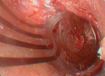
Fig. 2 Position of the film patch with integrated strain gauge (full bridge design) against the tympanic membrane.
Attachment of the film patch with integrated strain gauge to the tympanic membrane was assessed using optical coherence tomography scanning via the outer ear canal, in the same manner as for intra-operative scanning, for each of the two film patch designs.
Assessment of tympanic membrane movement with strain gauge
Three cadaveric temporal bones were prepared (Figure 3). Two plastic catheters were inserted into the eustachian tube opening, close to the site of the internal carotid artery. Silicon gel and candle wax were used to seal the eustachian tube opening in an airtight fashion. The anterior ends of the catheters were positioned under the tympanic membrane anterior to the umbo. The posterior end of the first plastic catheter was connected to a 5 cm3 syringe, and the posterior end of the second catheter was connected to a pressure-measuring sensor.

Fig. 3 Temporal bone preparation. Two plastic vein catheters were inserted into the eustachian tube opening close to the site of the internal carotid artery. Silicon gel and candle wax were used to seal the eustachian tube opening in an airtight fashion. One catheter was attached to a syringe used to create volume changes, the other catheter to a pressure sensor to measure pressure changes. The film patch with integrated strain gauge was positioned on the tympanic membrane. Data from the strain gauge and the pressure sensor were monitored simultaneously.
A film patch with integrated strain gauge was attached to the tympanic membrane as described above. The strain gauge was coupled to electronic data sampling and analysis devices, as previously described.Reference Lankenau, Klinger, Winter, Malik, Muller, Oelckers, Buzug, Holz, Weber, Bongartz, Kohl-Bareis and Hartmann6
By moving the syringe plunger (thereby introducing or removing 0.5–2 ml of air), positive and negative pressure changes were generated within the middle ear. The resulting outward and inward movements of the tympanic membrane were visualised endoscopically and detected by the strain gauge, generating data which were stored digitally. Pressure measurement results and strain gauge voltages were monitored simultaneously and recorded on a personal computer.
In order to determine whether the film patch could seal a tympanic membrane perforation, a diode laser was used to create such a perforation. Pressure changes were then monitored, following the procedure described above.
Results and analysis
Optical coherence tomography
An example of an optical coherence tomography scan of a normal tympanic membrane, and the corresponding tympanic membrane histology, is shown in Figure 4. The trilaminar structure of the tympanic membrane is clearly visible on the optical coherence tomography scan (comprising, from lateral to medial, a squamous layer, fibrous layer and cuboidal layer). Normally, tympanic membrane thickness ranges from 75 to 125 µm. However, in atrophic regions of the tympanic membrane the middle layer is lost. Figure 5 demonstrates the bilaminar structure of an atrophic tympanic membrane as viewed on optical coherence tomography. In contrast, in cases of myringosclerosis and chronic myringitis the thickness of the tympanic membrane exceeds 150 µm. Figure 6 shows an optical coherence tomography scan of a chronically inflamed tympanic membrane.
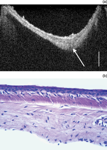
Fig. 4 (a) Optical coherence tomography scan of a healthy tympanic membrane. The three layers of the tympanic membrane are visible: from lateral to medial, the squamous, fibrous and cuboidal layers. The arrow indicates the umbo (scale bar = 200 µm). (b) Corresponding photomicrograph of the tympanic membrane (H&E; original magnification ×40).
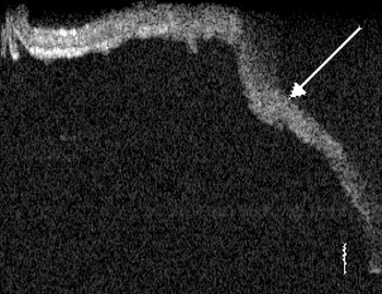
Fig. 5 Optical coherence tomography scan of an atrophic tympanic membrane. The trilaminar structure of the tympanic membrane is lost (arrow) (scale bar = 100 µm).
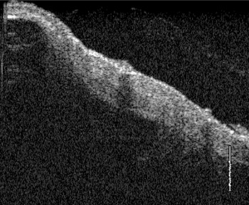
Fig. 6 Optical coherence tomography scan of a chronically inflamed tympanic membrane. The three layers are not clearly detectable (scale bar = 280 µm).
In the current study, optical coherence tomography was also used to assess the attachment between the tympanic membrane and the film patch with integrated pressure gauge (Figure 7). Optical coherence tomography was able to detect air bubbles between the tympanic membrane and the film patch, which could not be seen with an operating microscope.
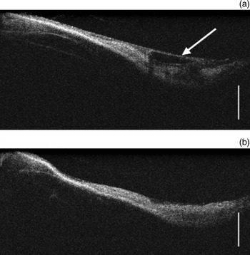
Fig. 7 Optical coherence tomography scan of a tympanic membrane with attached film patch with integrated strain gauge, (a) before and (b) after pressure changes within the middle ear. The latter scan demonstrates a small fluid collection beneath the film patch (arrow) (scale bar = 200 µm).
Furthermore, optical coherence tomography was able to detect the presence of small fluid collections between the tympanic membrane and the film patch, both before and after middle-ear pressure changes, for both types of film patch. Optical coherence tomography scanning revealed that the non-segmented film patch did not fit the tympanic membrane precisely, whereas the segmented film patch fitted better. It also became evident that both types of film patch were displaced slightly during middle-ear pressure changes.
Tympanic membrane perforations smaller than 2 mm could be sealed off with the film patch. In this setting, the film patch did not detach from the tympanic membrane in the presence of pressure changes of up to 2 ml (Figure 8). Perforations larger than 4 mm were not sealed reliably by the film patch.
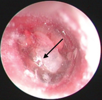
Fig. 8 Operating microscope view of a tympanic membrane with a small perforation (arrow). A transparent film patch is positioned over the perforation. No detachment of the film patch was seen after middle-ear volume changes of less than 2 ml.
Pressure measurement
Figure 9 shows middle-ear pressure measurements and corresponding strain gauge voltages for low pressure changes. The strain gauge voltage is seen to be directly proportional to the pressure measurement. At higher middle-ear pressures (resulting in higher amplitude movement of the tympanic membrane), change in the strain gauge voltage appears to be limited at pressure peaks and troughs (Figure 10). This is not due to any change in the electronic measuring devices, but rather to a mechanical separation of the strain gauge and its supporting film patch from the tympanic membrane surface, because of the limited flexibility of the film patch.
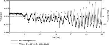
Fig. 9 Comparison of middle-ear pressure and strain gauge voltage over time, for low pressure changes (approximately ± 1 kPa). The strain gauge voltage is directly proportional to the pressure measurement.
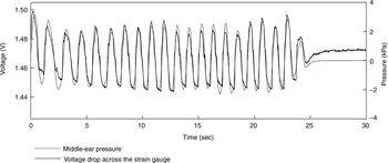
Fig. 10 Comparison of middle-ear pressure and strain gauge voltage over time, for high pressure changes (approximately ± 3 kPa). Beyond a certain high and low pressure limit, no further change in strain gauge voltage is observed (see text for explanation).
Discussion
In this study, we investigated the use of film patches with integrated strain gauges to monitor small pressure changes within the middle-ear cavity.
The morphology of healthy and pathological tympanic membranes was assessed using spectral domain optical coherence tomography and an operating microscope. Atrophic and sclerotic tympanic membranes could be differentiated from normal tympanic membranes. Furthermore, spectral domain optical coherence tomography was used to assess the attachment of two different types of film patch with integrated strain gauge (full bridge design) to the tympanic membrane, in the presence of changing middle-ear pressure, in temporal bone specimens. Small air and fluid collections were identified between the film patch and the tympanic membrane, along with slight movement of the film patch during middle-ear pressure changes. Despite this, it was still possible to assess the strain induced by pressure-dependent tympanic membrane movements, using the strain gauge. Strain gauge voltage changed either in phase with (Figure 9) or in opposition to the pressure measurement curve (not shown), depending on the magnitude of middle-ear pressure changes; extremely high or low pressures led to some detachment of the measuring film from the tympanic membrane.
Several different types of technology have been developed to measure eustachian tube function. Of these, tympanometry and sonotubometry should be mentioned.Reference Hergils, Magnuson and Falk1, Reference McBride, Decray, Cunningham and Doyle8, Reference Di Martino, Nath, Telle, Antweiler, Walther and Vary9 The latter technique uses a sound signal applied within the nose.Reference Di Martino, Nath, Telle, Antweiler, Walther and Vary9 A microphone in the ear canal records the signal transmitted from nose to ear. Different actions, such as water swallowing and the Toynbee manoeuvre, lead to changes in sound characteristics. However, tympanometry and sonotubometry are only useful where there is a functioning eustachian tube, and their value in patients without eustachian tube function is still unclear. A technique for assessing long-term eustachian tube function is required, in order to monitor transient and persistent periods of eustachian tube dysfunction.
In 2008, a method of assessing long-term eustachian tube function was developed which involved a small piece of flexible film with an integrated strain gauge.Reference Zehlicke, Behrend, Schmidt, Hoffmann, Müller and Pau5, Reference Sass, Zehlicke, Moß, Pau, Müller, Dössel and Schlegel7 The basic principle of this test comprised attachment of the film and strain gauge to the intact tympanic membrane, enabling continuous measurement of tympanic membrane movement and thus of changes in middle-ear ventilation, under near-physiological conditions. Improvement in film patch design is an ongoing process. In the current study, two different types of film patch were assessed using spectral domain optical coherence tomography. The tympanic membrane attachment of neither film patch was ideal; for both designs, small air and fluid collections were detected between the tympanic membrane and the film patch on optical coherence tomography. Nevertheless, the strain gauge was able to monitor precisely small pressure changes within the middle ear. When large pressure changes were introduced into the middle ear (approximately 3 kPa per second), the strain gauge failed to generate proportionally higher voltages due to partial detachment of the film patch from the tympanic membrane. However, rapid pressure changes of more than 2 kPa do not appear to occur under physiological conditions.
• There are currently no feasible methods for long-term clinical assessment of middle-ear function under physiological conditions
• An experimental device has recently been developed to achieve this aim, comprising a flexible film patch with integrated strain gauge
• Optical coherence tomography scanning indicated that attachment of this film patch to the tympanic membrane was not ideal
• Small pressure changes within the middle ear were precisely recorded, while large pressure changes led to partial detachment of the film patch
It is questionable whether it is possible to design an ideal film patch that completely matches the conical shape of the tympanic membrane, for the purpose of long-term assessment of eustachian tube function. Tympanic membrane morphology may change, for example due to atrophy, disease (e.g. chronic inflammation, myringosclerosis and chronic myringitis) or cartilage reconstruction, leading to difficulty attaching the film patch.


