


Introduction
In cases of posterior glottic stenosis, stenting of the airway is usually necessary in addition to grafting. Laryngeal stents are mainly used to keep the airway patent so as to maintain its lumen and to stabilise and immobilise the cartilage graft following surgical reconstruction.Reference Ochi, Evans and Bailey1 However, these stents can act as foreign bodies and can induce granulation tissue formation, thereby causing subsequent re-stenosis. Patients may also have silent aspiration if the stent is not anatomically conformed to the laryngeal inlet or is hollow.
An ideal laryngeal stent should be: (1) soft and pliable, causing less mucosal damage; (2) conforming to airway contours (customisable to fit the airway); (3) biocompatible; (4) able to maintain airway anatomy; (5) able to move with the larynx during respiration and deglutition without migrating; (6) readily available; and (7) affordable.
Currently, the LT-MoldTM, designed by Professor Philippe Monnier, is one such stent fulfilling almost all of the above criteria but is not marketed for sale and hence unavailable. Therefore, we designed a stent which would fulfil the above criteria and used it in a case of posterior glottis stenosis treated with expansion laryngoplasty.
Customised laryngeal stent
The laryngeal stent that was used for our patient was created from a number 14 Montgomery T-tube (a long silastic tube being unavailable). The long vertical limb of the T-tube was cut and separated from the rest of the tube (Figure 1). The distance between the vocal fold (anterior commissure) and the superior margin of the tracheostoma was measured, and a point ‘A’ was marked on the vertical limb from its distal end, which was 3 cm in our case (Figure 2a). Two gently arched symmetrical lines AB1 and AB2 were drawn from point A at approximately 45° to the horizontal to two diametrically opposite points, B1 and B2, respectively.
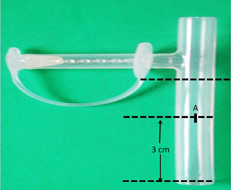
Fig. 1. Vertical limb of Montgomery T-tube that was cut to design a laryngeal stent. The distance between the vocal fold and superior margin of tracheostoma is measured on vertical limb of the T-tube (i.e. 3 cm). A = distance between the vocal fold (anterior commissure) and the superior margin of the tracheostoma measured and marked as A from the distal end of tube.

Fig. 2. Stepwise designing of a new laryngeal stent using a silicon Montgomery T-tube. (a) Distance between the vocal fold and the superior margin of the tracheostoma measured from the distal end of the tube, marked as A. (b) Horizontal line drawn at 45 degrees from point A and labelled as B1 and B2. Anterior half of tube sectioned vertically at its proximal end. (c) Posterior flap trimmed in triangle shape to fold anteriorly (point C). (d) Triangular posterior flap sutured anteriorly.
The tube was then vertically sectioned along its diameter from the proximal end, until points B1 and B2, and along lines AB1 and AB2 (Figure 2b). The posterior flap thus created was further trimmed and designed into a triangle with an apex point C, such that C can fit into A when folded forwards (Figure 2c). This triangular posterior flap was sutured to the cut edge of the anterior half of the tube with a 4-0 prolene suture with a continuous stitch (Figure 2d). This not only closed the proximal end, thus protecting the airway, but also created a tube conforming to the contour of the laryngeal lumen.
Case report
A 19-year-old male patient who had grade III posterior glottis stenosis with restriction of vocal fold movements, a tracheotomy and a normal distal airway was referred to us for further management. The patient was treated by laryngofissure with a posterior cricoid split and interposition of costal cartilage graft followed by placement of the customised stent. This stent was stabilised with two non-absorbable prolene 3-0 stitches, one through the lateral wall of the trachea and one in the supraglottis through the ventricular bands. The latter stitch is important as it fixes the stent in the right position (i.e. at the level of the glottis; Figure 3a and b). The stent was smeared with steroid ointment before insertion to prevent granulation tissue formation.

Fig. 3. (a) Laryngofissure with placement of posterior costal cartilage graft. (b) New laryngeal stent placed over posterior graft and prolene stitch secured at the level of anterior commissure.
The accuracy of the placement of the stent in the glottis region was confirmed with a 0-degree endoscope, and the laryngofissure was then closed on the refashioned stent (Figure 4a). The neck wound was closed in layers, leaving a corrugated drain and tracheostomy tube in situ. The patient was given broad-spectrum antibiotics, analgesics and anti-reflux treatment, and a nasogastric tube was inserted for feeding. Oral feeding was started five days after surgery and no aspiration was noted. The patient was advised to avoid forceful coughing to prevent accidental expulsion of the stent, and the patient was then discharged.

Fig. 4. Endoscopic images showing: (a) intra-operative confirmation of stent, (b) endoscopic view of stent at one-month post-surgery, (c) uncapping of stent, (d) cutting of stay sutures, (e) removal of stent and (f) after stent removal.
After one month, a transoral rigid endoscopy was done under general anaesthesia, and the sutures holding the proximal cap were first cut. Scissors were then passed through the lumen of the stent and then the sutures holding the stent in place were cut, and the stent was removed (Figure 4b–f). The laryngeal mucosa was inflamed with minimal granulation tissue. Further endoscopies were performed to assess the integrity of the cartilage graft, the calibre of the airway and to look for any granulation tissue formation. The prosthesis seemed to be well tolerated as the mucosa healed very well with no fibrosis. On the 45th post-operative day, the tracheostomy tube was removed (Figure 5a and b). At 8 months follow up, the patient was asymptomatic with a good airway and voice and no aspiration.

Fig. 5. Endoscopic images showing: (a) pre-operative endoscopic view of glottis stenosis, (b) immediately after stent removal and (c) two weeks after stent removal showing expanded glottis area.
Discussion
Laryngotracheal stenosis rates have shown a rise in recent years probably because of prolonged intubation and tracheostomy for more complex medical conditions. Posterior glottic stenosis with or without subglottic involvement is managed by laryngofissure with anterior or posterior cricoid grafting or both. The reconstructed area requires stenting in most cases to stabilise the graft while healing occurs.
The majority of commercially available stents are either cylindrical or T-shaped, open-ended and do not conform to the complex triangular anatomy of the glottis. Moreover, the upper end of these stents is positioned over the false vocal folds, which causes aspiration and dysphonia; hence there is a need for a better stent. We designed a new laryngeal stent using the vertical portion of a Montgomery T-tube. The reasons for using this T-tube were: (1) it is made up of silastic and is therefore smooth and pliable; (2) it can be cut and moulded to the required shape and dimensions; (3) the edges can be easily smoothed; (4) it is well tolerated and causes less mucosal reaction; and (5) it is available in various sizes.
The duration of stenting depends on the stability of the reconstructed area at the end of the procedure. According to Zalzal, the minimum time necessary for cartilage graft and posterior cricoid split to heal is two weeks.Reference Zalzal2,Reference Zalzal3 In our patient, the stent was kept for one month.
• Airway reconstruction surgery for posterior glottis stenosis is a challenge and requires grafting with stenting for a desirable outcome
• A new customised laryngeal stent was well-tolerated and was effective in the surgical repair of posterior glottis stenosis
• The new stent enabled early reintroduction of oral feeding with no aspiration and a healthy patent airway with early decannulation
• The design of the prosthesis, conforming to the shape of the larynx, helped prevent formation of granulation tissue
• This first case is promising, but further experience in treating laryngotracheal stenosis using this stent will be required
The overall benefits with this new stent are: (1) it is well tolerated (biocompatible, so less tissue reaction); (2) it conforms to the shape of the larynx and has no sharp edges, and so there is no mucosal reaction and granulation tissue formation; (3) the upper end is closed, and so there is no risk of aspiration, and oral feeding can be started early; (4) there is no risk of extrusion because the proximal cap is fashioned out of the same tube, and the tube is secured to the larynx and trachea by non-absorbable sutures; (5) it can be easily removed transorally by cutting the sutures; (6) it is readily available in different lengths and diameters; and (7) it can be easily designed with no added surgical time.
Acknowledgements
We thank Professor Philippe Monnier for generously sharing his knowledge and experience.
Competing interests
None declared


