


1. Introduction
Shock interactions are widely encountered in supersonic and hypersonic flows and can significantly enhance heating/pressure loads (Wieting & Holden Reference Wieting and Holden1989) on vehicle surfaces and even damage flight vehicles. Due to the fundamental interest and practical applications, tremendous efforts have been made to investigate the shock interactions on canonical configurations, including a double wedge (Ben-Dor et al. Reference Ben-Dor, Vasilev, Elperin and Zenovich2003; Durna, Barada & Celik Reference Durna, Barada and Celik2016), a double cone (Druguet, Candler & Nompelts Reference Druguet, Candler and Nompelts2005; Tumuklu, Levin & Theofilis Reference Tumuklu, Levin and Theofilis2018), spiked blunt bodies (Panaras & Drikakis Reference Panaras and Drikakis2009), and so on. As a benchmark study, Edney (Reference Edney1968) classified shock interactions as types I to VI according to the shock strengths and intersection positions. This classification scheme provided a guideline for subsequent research on flow characteristics (Olejniczak, Wright & Candler Reference Olejniczak, Wright and Candler1997), heating/pressure loads (Wieting & Holden Reference Wieting and Holden1989) and unsteady oscillations (Zhong Reference Zhong1994). Nevertheless, shock interactions still pose new challenges to researchers as more complicated configurations are exposed in practical situations.
Recently, the V-shaped cowl lip, which is generally encountered in a hypersonic inward-turning inlet (Malo-Molina et al. Reference Malo-Molina, Gaitonde, Ebrahimi and Ruffin2010; Gollan & Smart Reference Gollan and Smart2013; Bisek Reference Bisek2016), has attracted increasing attention (Zhang et al. Reference Zhang, Li, Li and Yang2019a,b,c; Wang et al. Reference Wang, Li, Zhang, Liu, Yang and Lu2018, Reference Wang, Li, Zhang and Yang2020; Xiao et al. Reference Xiao, Li, Zhang, Zhu and Yang2018; Li et al. Reference Li, Zhang, Wang and Yang2019) because the detached shock waves from the blunt leading edges of the V-shaped cowl cause complex interactions on the crotch. In our previous works, Xiao et al. (Reference Xiao, Li, Zhang, Zhu and Yang2018) first proposed a V-shaped blunt leading edge (VBLE) (see figure 1) to reveal the complicated flow and surface heat fluxes on the V-shaped cowl. It has been shown that the ratio  $R/r$ (defined as the ratio of the crotch radius
  $R$ to the leading edge radius
  $r$), the half-span angle
  $\beta$ and the free stream Mach number significantly affect the shock interactions on VBLEs, and these interactions are classified into three types: regular reflection (RR), Mach reflection (MR) and regular reflection from the same family (sRR). As complex shock interactions are generally accompanied by severe heating loads, Xiao et al. (Reference Xiao, Li, Zhang, Zhu and Yang2018), Li et al. (Reference Li, Zhang, Wang and Yang2019) and Wang et al. (Reference Wang, Li, Zhang and Yang2020) pointed out that the geometry of a VBLE plays an important role in reducing the peak heating/pressure loads rather than simply increasing the leading edge radius according to traditional experience (Fay & Riddell Reference Fay and Riddell1958). Moreover, Wang et al. (Reference Wang, Li, Zhang, Liu, Yang and Lu2018) and Zhang et al. (Reference Zhang, Li, Huang and Yang2019b) observed four typical self-sustained shock oscillation patterns in the MR and sRR regimes, and these patterns are sensitive to the geometry of the VBLE. These previous works indicated that small changes in the geometry of a VBLE can lead to large changes in the overall shock structures and peak heating/pressure loads. However, knowledge of the transition mechanisms and criteria of shock interactions on VBLEs remains lacking.

Figure 1. The VBLE model:  $(a)$ schematic diagram;
  $(b)$ test model assembly.
Among the theories of shock interactions in steady flows, the classic von Neumann criterion and detachment criterion (Ben-Dor Reference Ben-Dor2007), which have successfully predicted transitions between RR and MR on canonical configurations, are commonly used. Theoretically, only RR exists when the flow turning angle behind a shock is below the von Neumann criterion, whereas only MR exists when the flow turning angle behind a shock is above the detachment criterion. Both RR and MR are admissible between the von Neumann criterion and detachment criterion. However, a preliminary study by Zhang et al. (Reference Zhang, Li, Xiao, Zhu and Yang2019c) found that the transition from RR to MR could occur below the von Neumann criterion for shock interactions on VBLEs. This abnormal phenomenon suggests the specificity of VBLEs. Since the classic criteria depend only on the flow conditions, it can be implied that additional conditions induced by the geometry should be considered for VBLEs.
In reality, similar situations have been encountered in some canonical configurations, where an imposed downstream flow condition (Ben-Dor et al. Reference Ben-Dor, Elperin, Li and Vasilev1999) or a geometric constraint (Olejniczak et al. Reference Olejniczak, Wright and Candler1997; Hu et al. Reference Hu, Wang, Zhang and Myong2009a,b Reference Hu, Myong, Kim and Cho, Reference Hu, Gao, Myong, Dou and Khoo2010) makes the classic von Neumann and detachment criteria (Ben-Dor Reference Ben-Dor2007) fail to predict the shock interaction types. Addressing these situations becomes more difficult, and thus, numerical simulations are helpful. For instance, Olejniczak et al. (Reference Olejniczak, Wright and Candler1997) numerically obtained transition criteria for shock interactions in hypersonic double-wedge flows in the presence of downstream subsonic flow. To characterize downstream conditions for shock interactions on a double wedge, Hu et al. (Reference Hu, Gao, Myong, Dou and Khoo2010) proposed a geometric transition criterion between RR and MR using numerical simulations. These works created an obvious motivation to study geometric constraints imposed by VBLEs in an effort to ultimately devise transition criteria for the shock interactions.
In this work, the shock interactions on VBLEs at a Mach number of 6 are systematically examined using a combination of shock tunnel experiments, numerical simulations and theoretical analyses. Specifically, the transitions of the shock interactions induced by both  $R/r$ and
  $\beta$ are revealed, providing deep insight into the geometric constraints of VBLEs. Then, transition criteria from RR to MR and from MR to sRR are established for shock interactions on VBLEs, and these criteria guide the design of the V-shaped cowl. The rest of this paper is organized as follows: models and the experimental set-up are introduced in § 2; numerical methods are given in § 3; theoretical analyses are presented in § 4; detailed results and discussion on wave configurations with various parameters are given in § 5; and finally, conclusions are summarized in § 6.
2. Models and experimental set-up
As shown in figure 1 $(a)$, VBLEs are symmetrical about the
  $x$–
$x$– $y$ and
  $x$–
$x$– $z$ planes, where the coordinates
  $x$,
$x$,  $y$,
$y$,  $z$ and
  $\varphi$ denote the streamwise, transverse, spanwise and circumferential directions, respectively. The VBLE model consists of two straight branches and a crotch and is characterized by a half-span angle
  $\beta$, a curvature radius
  $R$ of the crotch and a fixed leading-edge bluntness
  $r = 2\ \textrm {mm}$. The length of a straight branch is
  $L = 30r$, along which a detached shock (DS)develops.
Experiments were conducted in the KDJB330 reflected shock tunnel (Li et al. Reference Li, Gao, Jiang and Yang2013) of the University of Science and Technology of China with a nominal free stream Mach number of 6 and an effective experimental time of approximately 20 ms. The stagnation pressure and temperature were approximately 1.97 MPa and 1000 K, respectively, corresponding to a unit Reynolds number of  $5.6\times 10^{6}\ \textrm {m}^{-1}$. A high-speed schlieren photography system was equipped to capture the shock interactions. Schlieren images were acquired using a Phantom v611 camera with a frame rate of 50 kHz and an exposure time of
  $1\ \mathrm {\mu }\textrm {s}$. To obtain the detailed flow features of the shock interactions, enlarged models (see figure 1
 $b$) with proper magnification factors relative to the aforementioned size (i.e.
  $r = 2\ \textrm {mm}$) were adopted. Considering the limitation of the tunnel nozzle's exit area, magnification factors of 2.5–4 were used. In other words, significantly different values of
  $R$ and
  $r$ were employed in the experiments to yield the same value of
  $R/r$ as that in numerical simulations. Numerical results (Wang et al. Reference Wang, Li, Zhang, Liu, Yang and Lu2018; Xiao et al. Reference Xiao, Li, Zhang, Zhu and Yang2018) have shown that magnification factors have little impact on the shock structures under the conditions of the current study. All experimental models are listed in table 1, which gives an overview of the parameters.
Table 1. Overview of the experimental models.

3. Numerical methods
In addition to the experiments, numerical simulations were performed to provide fine flow structures for a large range of geometric parameters. A three-dimensional Reynolds-averaged Navier–Stokes solver based on the finite volume method was conducted. Roe's flux difference splitting scheme was employed for spatial discretization of inviscid fluxes (Roe Reference Roe1981). The convective and viscous terms were discretized by a second-order upwind scheme and a second-order central difference scheme, respectively. Although the flow (particularly upstream) at a straight branch of a VBLE is most likely in the laminar state according to the unit Reynolds number of the free stream, the complicated shock interactions at the crotch greatly amplify the turbulence generation (Wang et al. Reference Wang, Li, Zhang, Liu, Yang and Lu2018), and thus, a fully turbulent flow was assumed for the current simulations. The Spalart–Allmaras turbulence model (Spalart & Allmaras Reference Spalart and Allmaras1992) was chosen to model the turbulence. The equation of state for an ideal gas with the specific heat ratio  $\gamma = 1.4$ was employed, and the molecular viscosity of the gas was assumed to obey Sutherland's law.
A three-dimensional computational domain and boundary conditions are shown in figure 2( $a$), and the domain consists of the inflow, outflow and solid wall. The inflow boundary conditions are consistent with current experiments (i.e. free stream Mach number
  $Ma_\infty = 6$, static pressure
  $p_\infty = 1247\ \textrm {Pa}$ and static temperature
  $T_\infty = 122\ \textrm {K}$). The flow quantities at the outflow boundary are extrapolated from the interior flow. No-slip and isothermal solid wall boundaries were applied on the VBLEs with a fixed temperature of 300 K. The grid distribution near the crotch with a quarter of the domain removed is illustrated in figure 2(
 $b$), where
  $\xi$,
  $\zeta$ and
  $\psi$ represent the numbers of grid points around the crotch along the wall normal, circumferential and spilling directions, respectively. The surface cell thickness yields a wall
  $y^{+}$ of less than 1, and the grid size increases gradually away from the wall. When the pressure variation of the stagnation point was kept less than 0.1
 $\%$, along with the stability of continuity and velocity residuals, the numerical solution was considered to converge.

Figure 2.  $(a)$ Computational domain and boundary conditions.
  $(b)$ Grid near the crotch.
A typical VBLE with  $\beta =24^{\circ }$,
  $R = 10\ \textrm {mm}$ and
  $r = 2\ \textrm {mm}$ was adopted for a grid independence study. Four sets of structured grids (i.e. coarse, fine, dense and refined grids) are given in table 2. The coarse and fine grids have a surface cell thickness of
  $1 \times 10^{-6}\ \textrm {m}$, whereas the dense and refined grids have a surface cell thickness of
  $5 \times 10^{-7}\ \textrm {m}$. The wall pressure distributions on the centreline (
 $y = 0$) of the crotch obtained by the four sets of grids are compared in figure 3(
 $a$). The nearly identical wall pressure distributions indicate that the grid resolutions have reasonable convergence. Moreover, the velocity profiles at
  $x = 5r$ upstream of the stagnation point of the dense and refined grids are extracted and compared in figure 3(
 $b$), showing good agreement. Therefore, the dense grid is sufficient for the simulations and is used in the following sections.
Table 2. Four sets of grids used in the grid convergence study.


Figure 3. Comparison of various grid resolutions.  $(a)$ Surface pressure along the leading edge centreline (
 $y = 0$).
  $(b)$ Velocity profiles normal to the wall.
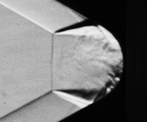
As shown in figure 4, the numerical results (see the lower part) are validated against experiments (see the upper part) in the form of schlieren images for three typical wave configurations. The shock waves in front of the crotch are in good agreement with the experiments, which shows the reliability of the numerical simulations. Comprehensive comparisons and detailed discussions on wave configurations are given in appropriate locations in § 5.

Figure 4. Comparisons between the experimental (Exp.) and numerical (Num.) results.
4. Theoretical analysis
To better understand the wave configurations on VBLEs, theoretical analyses of shock waves on the two parts (i.e. the straight branch and the crotch, see figure 1 $a$) are illustrated in figures 5 and 6, respectively. Moreover, a brief introduction of the shock interactions between the two parts is presented in this section.

Figure 5. Straight branch.  $(a)$ Sketches of the DS.
  $(b)$ The shock standoff distance.

Figure 6. Crotch part.  $(a)$ Sketches of the CS.
  $(b)$ Comparison of the CS between the experimental and theoretical results.
As shown in figure 5( $a$), the straight branch is essentially a swept cylinder. When the half-span angle
  $\beta$ is larger than the Mach angle (i.e.
  $Ma_\infty \ast \sin \beta >1$), a DS generated from this swept cylinder gradually develops along the wall and eventually reaches a fully developed state, which yields a constant standoff distance,
  $\delta _1$. As a result, the DS on the
  $x$–
$x$– $z$ symmetry plane is presented as an oblique shock with a shock angle equal to
  $\beta$. When the flow behind the DS is subsonic, the crotch of the VBLE can generate disturbances that affect the upstream flow and the shape of the DS. Thus, this study focuses on cases that the post-shock Mach number of DS in the symmetry plane is larger than one. In other words, the flow behind the DS remains supersonic in the present study. To obtain the position of this oblique shock (i.e. DS), the incoming flow is decomposed along the directions vertical and parallel to the oblique shock. The velocity component parallel to the oblique shock remains constant, whereas the velocity component vertical to the oblique shock experiences compressions and is reduced to zero on the wall. In other words, these vertical compressions are equivalent to those of a cylinder with a radius
  $r$ against the vertical velocity component. Following the inviscid theoretical approximation proposed by Sinclair & Cui (Reference Sinclair and Cui2017),
  $\delta _1$ (see figure 5
 $a$) is obtained using the equation
  $\delta _1/r = f(Ma_\infty \ast \sin \beta$), where the function
  $f$ depends only on the vertical component of the incoming flow
  $Ma_\infty \ast \sin \beta$.
Comparisons of the shock standoff distance between the theoretical results ( $\delta _1$) and the numerical results (
 $\delta _1'$) are shown in figure 5(
 $b$). Although the theoretical estimations do not take into account the viscosity effects, they closely agree with the numerical results for
  $\beta \geq 24^{\circ }$. It seems that the boundary layer on the straight branch has little impact on the shock standoff distance in the current conditions. On the other hand, the difference between
  $\delta _1$ and
  $\delta _1'$ slightly enlarges with a decrease in
  $\beta$, as shown in figure 5(
 $b$), and this finding is mainly due to the limited length of the straight branch. Generally, it is harder for a DS to reach a fully developed state with a smaller value of
  $\beta$ because of the weaker vertical compression. For consistency,
  $\delta _1'$ is used to evaluate the shock structures determined from the numerical results in § 5.3.2. As the shock standoff distance is obtained, the DS position on the
  $x$–
$x$– $z$ symmetry plane is known in advance.
Note that the flow from the DS to the wall in the  $x$–
$x$– $z$ symmetry plane is uneven, which is different from the uniform flow behind a two-dimensional oblique shock. As mentioned previously, the velocity component parallel to the DS in the
  $x$–
$x$– $z$ symmetry plane remains constant across the shock. The challenging work is estimating the vertical velocity component from the DS to the wall. According to the inviscid theoretical approximation proposed by Sinclair & Cui (Reference Sinclair and Cui2017), the Mach number along the stagnation line of a cylinder decreases linearly from
  $M_{n2}$ (i.e. the vertical component just behind the DS in the present study) to zero at the wall (see figure 5
 $a$). Subsequently, one can theoretically estimate the local temperature, velocity components and flow deflection angles
  $\theta$ from the DS to the wall because the inviscid flow behind the DS in the
  $x$–
$x$– $z$ symmetry plane is isentropic. To summarize, the shock angle
  $\beta$, position of the DS and flow parameters from the DS to the wall in the
  $x$–
$x$– $z$ symmetry plane are all determined by the free stream Mach number
  $Ma_\infty$ and half-span angle
  $\beta$, regardless of the ratio
  $R/r$.
As shown in figure 6( $a$), the crotch is tangential to the straight branch, which isentropically compresses the supersonic flow behind the DS and generates compression waves (CWs) in the
  $x$–
$x$– $z$ symmetry plane. As the CWs travel downstream, they coalesce into a curved shock (CS). It is of great importance to reveal this CS because it can affect the overall shock structures on the crotch. Since the inflow conditions for the CWs and the CS (i.e. the flow parameters from the DS to the wall) are known in advance, the parameters associated with the CWs and the CS can be estimated theoretically using an iterative procedure. This procedure is similar to the calculation of a stratified non-uniform supersonic flow past a curved wall (Emanuel Reference Emanuel1982, Reference Emanuel1983). First, the circular crotch is discretized as a series of straight walls with a small deflection angle of
  $0.05^{\circ }$. Convergence solutions can be obtained with such a sufficiently small element. Each straight wall produces an isentropic CW in the local supersonic flow from the wall. Second, the intersection of the first two adjacent CWs from the same family is analytically solved to obtain the starting point of the coalescent shock. Third, the following CWs from the crotch successively catch up with the coalescent shock and deform it to form the aforementioned CS. In other words, the limiting envelope of the CWs forms the shape of CS. These interference processes are analytically solved one by one repeatedly to obtain the CS. As shown in figure 6(
 $b$), the theoretical CS (dashed line) agrees well with the experimental result. Note that the CS depends on both the half-span angle
  $\beta$ and the ratio
  $R/r$ that determine the local upstream flow parameters. Therefore, the shape of the CS (
 $x_{CS}$,
  $z_{CS}$) is expressed as
 \begin{equation} F\left(\frac{x_{CS}}{r},\frac{z_{CS}}{r},Ma_\infty, \frac{R}{r},\beta\right)=0 \end{equation}
 Keep in mind that not only two DSs from opposite families but also a DS and a CS from the same family can interact near the crotch (see figure 4). Since the shapes and positions of the DS and the CS in the  $x$–
$x$– $z$ symmetry plane are obtained theoretically, the admissible shock interaction types between these shocks can be solved using shock polar diagrams, in which the pressure jump
  $p$ across a shock wave is plotted versus the corresponding flow deflection angle
  $\theta$. Briefly, a shock polar represents the locus of the flow state obtained by passing through a shock wave at a given Mach number. Thus, the entire region behind a given shock wave is represented by a single point on the (
 $p$,
$p$,  $\theta$) diagram, whereas the intersection of the shock polar determines the possible shock interaction types.
In reality, a downstream disturbance originating near the stagnation point of the crotch challenges theoretical determinations of shock interaction types (i.e. RR, MR and sRR) on a given VBLE, the flow physics of which is discussed in §§ 5.1 and 5.2. Subsequently, the establishment of the theoretical transition criteria from RR to MR and from MR to sRR is a main subject of the present work, as discussed in § 5.3.
5. Results and discussion
In this study, the half-span angle  $\beta$ is theoretically restricted in the range of
  $9.6^{\circ }\text {--}66^{\circ }$ to ensure that a DS can be generated from the straight branch and that the post-shock Mach number is larger than 1, whereas the ratio
  $R/r$ ranges from 0 to 9 to cover the transitions of shock interactions on the VBLEs. For a better understanding, the evolution of shock interactions induced by each geometric parameter is presented first. The transitions of shock interactions in this parameter space (i.e.
  $R/r$ and
  $\beta$) are then discussed.
5.1. Effects of the ratio  $R/r$
$R/r$

The ratio  $R/r$ mainly imposes two effects on the shock interactions: one effect occurs via the shapes of the CWs and the CS from the crotch; the other effect occurs via the buffer space for the accumulating stream in front of the stagnation point. To reveal the mechanisms of these effects, two typical half-span angles
  $\beta = 24^{\circ }$ (below the classic von Neumann criterion
  $\beta ^{vN}$) and
  $40^{\circ }$ (above the classic detachment criterion
  $\beta ^{D}$) are discussed in this section.
5.1.1. Half-span angle $\beta = 24^{\circ }$

Experimental schlieren images corresponding to small ratios  $R/r$ ranging from 0 to 1 are shown in figure 7, providing a first glance at the shock structures in front of the crotch. For a better description, sketches of the typical shock structures at
  $R/r = 0.875$ and 1 are illustrated in figure 8. As the flow comes from the left, pairs of detached shocks (DS
 $_1$ and DS
 $_2$) derived from the blunt straight branches are first observed. Although DS
 $_1$ and DS
 $_2$ are determined by the half-span angle regardless of
  $R/r$ (see § 4), variations in shock interference between DS
 $_1$ and DS
 $_2$ are observed with increasing
  $R/r$.

Figure 7. Experimental schlieren images at  $\beta = 24^{\circ }$ for
  $R/r$ ranging from 0 to 1:
  $(a)$
$(a)$  $R/r = 0$;
  $(b)$
$(b)$  $R/r = 0.875$;
  $(c)$
$(c)$  $R/r = 1$.

Figure 8. Sketches of shock structures from RR to MR:  $(a)$
$(a)$  $R/r = 0.875$;
  $(b)$
$(b)$  $R/r = 1$.
  $(c)$ Shock polar diagram.
As shown in figures 7( $a$) and 7(
 $b$), DS
 $_1$ and DS
 $_2$ from opposite families intersect directly at
  $R/r = 0$ and 0.875, which forms a primary RR. Downstream of the intersection point (IP), the transmitted shocks (TS
 $_1$ and TS
 $_2$) impinge on the wall, causing local circumfluence and separation shocks (SS
 $_1$ and SS
 $_2$). Separation shocks SS
 $_1$ and SS
 $_2$ intersect at IP
 $_1$ (see figure 8
 $a$), which is located downstream of the IP. Thus, the primary RR between DS
 $_1$ and DS
 $_2$ is not affected by the disturbances generated from the separation regions. Of great interest, the circular crotch wall significantly increases the adverse pressure gradient for
  $R/r = 0.875$, and this effect sharply enlarges the downstream flow separation regions (see figure 7
 $b$). As a result, IP
 $_1$ moves significantly upstream towards the IP. When
  $R/r$ increases further, the downstream disturbances reach the original IP and thus terminate the primary RR. As shown in figures 7(
 $c$) and 8(
 $b$), DS
 $_1$ and DS
 $_2$ form a Mach stem (MS) in front of the crotch and form a primary MR at
  $R/r = 1$. The TS
 $_1$ and TS
 $_1$ and shear layers (SL
 $_1$ and SL
 $_2$) are emitted from the triple points (TP
 $_1$ and TP
 $_2$). In concurrence with the MR structures, shear layer-bounded supersonic jets are formed. These jets travel downstream along the wall and collide near the stagnation point. As a result, a large counter-rotating vortex pair (CVP) is formed downstream of the MS and creates the specific stagnation and accumulation effects of the crotch. For more detail, one can refer to our previous papers (Wang et al. Reference Wang, Li, Zhang, Liu, Yang and Lu2018; Xiao et al. Reference Xiao, Li, Zhang, Zhu and Yang2018). Two types of shock interactions (i.e. RR and MR) between DS
 $_1$ and DS
 $_2$ are observed with a small change in
  $R/r$, indicating that these phenomena are sensitive to
  $R/r$.
The theoretically admissible shock interaction types between DS $_1$ and DS
 $_2$ are analysed in figure 8(
 $c$) using shock polar diagrams. The flow deflection angle
  $\theta$ for DS
 $_1$ is determined from its shock angle
  $\beta = 24^{\circ }$, and thus, the polar for DS
 $_1$ is plotted on the free stream polar (
 $\infty$). Because the flow deflection angle matches the shock angle one-to-one in the current study, the shock angle is used for a better description of the shock polar. The classic von Neumann criterion (Ben-Dor Reference Ben-Dor2007) is also plotted in figure 8(
 $c$) corresponding to a shock angle
  $\beta ^{vN} = 29^{\circ }$. Theoretically, only RR exists when the shock angle of DS
 $_1$ is below
  $\beta ^{vN}$. However, both RR and MR are observed for
  $\beta = 24^{\circ }$ (see figure 7), which are marked by black dots in figure 8(
 $c$). This surprising discrepancy indicates that the transition from RR to MR is advanced for the VBLEs, and the classic criterion fails to predict this transition. Actually, the shock polar diagrams do not take into account the influence of the circular crotch. Thus, additional conditions from the geometry should be sought to establish a new criterion, which is given in § 5.3.
Experimental schlieren images corresponding to large ratios  $R/r$ ranging from 3 to 6 are shown in figure 9(
 $a\text {--}c$). Although DS
 $_1$ and DS
 $_2$ still form a primary MR for
  $R/r = 3$ and 5, the MS changes to a long arched shape (see figure 9
 $a{,}b$) due to the impact of the CVP behind the MS. For more detail, one can refer to our previous papers (Wang et al. Reference Wang, Li, Zhang, Liu, Yang and Lu2018; Xiao et al. Reference Xiao, Li, Zhang, Zhu and Yang2018; Li et al. Reference Li, Zhang, Wang and Yang2019). As shown in the enlarged view in figures 9(
 $a$) and 9(
 $b$), a CS, rather than a separation shock, is generated as the upstream supersonic flow along the straight branch encounters the converging wall at the junction of the straight branch and the crotch (i.e. the elbow). The CS and a TS emitted from the TP form a secondary MR (see figure 9
 $a$) and a secondary RR (see figure 9
 $b$) near the wall for
  $R/r = 3$ and 5, respectively. With a further increase in
  $R/r$, the CS in the secondary RR reaches the TP in the original primary MR and thus changes the primary shock structures significantly. As shown in figure 9(
 $c$), the CS directly intersects with the DS from the same branch at the IP
 $_3$, generating an sRR for
  $R/r = 6$. Moreover, the original arch-shaped MS in front of the crotch is replaced by a concave bow shock (BS). To obtain a deep understanding of this sRR configuration, sonic lines are superimposed on the numerical schlieren image shown in figure 9(
 $d$). For a better description of the variation in the primary shock structures, sketches of the enlarged views in figures 9(
 $b$) and 9(
 $c$) for
  $R/r = 5$ and 6 are illustrated in figures 10(
 $a$) and 10(
 $b$), respectively. When the primary shock structures change to an sRR configuration, expansion waves (EWs), an SL and a TS are emitted from the IP to meet the flow compatibility. Note that the EWs, rather than a shock wave, impinge on the wall. This change in the shock structures implies that the sRR configuration has the potential to reduce surface pressure/heating loads.

Figure 9.  $(a\text {--}c)$ Experimental schlieren images for
  $R/r$ ranging from 3 to 6 at
  $\beta = 24^{\circ }$.
  $(d)$ Numerical schlieren images for
  $R/r = 6$.

Figure 10. Sketches of shock structures:  $(a)$
$(a)$  $R/r = 5$;
  $(b)$
$(b)$  $R/r = 6$.
As shown in figure 10, the transition from the primary MR to sRR involves shock interactions changing from opposite families (i.e. DS $_1$ and DS
 $_2$) to the same family (i.e. DS and CS), which is determined by both the relative positions of these upstream shocks and the accumulation effects of the downstream crotch. Although the positions and shapes of the DS and CS can be theoretically obtained under the assumption of no interference (see § 4), the position of the TP in the primary MR is difficult to evaluate by classic theories. To establish a criterion for the transition from the primary MR to sRR, additional conditions from the geometry should be sought, as given in § 5.3.
When  $R/r$ increases further, the DS and CS still form the sRR configuration; however, the subsonic region behind the BS shrinks with the enlargement of buffer space for the accumulating stream. For instance, a numerical schlieren image and sonic lines for
  $R/r = 8.5$ are presented in figure 11(
 $a$), where the supersonic region downstream of the IP
 $_3$ is obviously enlarged and the TS is elongated compared with those for
  $R/r = 6$ (see figure 9
 $d$). For a better description of these variations in the sRR configuration, a sketch of the shock structures near the IP
 $_3$ and the corresponding shock polar diagram are shown in figure 11(
 $b$), where the four numbered regions in the sketch are consistent with the numbered points in the shock polar diagram. Because the IP3 is the intersection of the DS and CS, the shapes of these shocks are obtained using the theories presented in § 4. Subsequently, the flow state of region (1) behind the DS and the flow state of region (2) behind the CS are determined according to their shock angles. As the flow state of region (3) is expanded from region (2) via EWs, an isentropic expansion path connects regions (2) and (3) on the shock polar diagram. The flow state of region (4) behind the TS is on the free stream shock polar (
 $\infty$). Note that regions (3) and (4) are separated by a contact discontinuity, and thus, they share the same position on the free stream shock polar. In other words, the isentropic expansion path originating from point (2) intersects with the free stream shock polar, and this intersection yields the locations of points (3) and (4). As shown in figure 11(
 $b$), when
  $R/r$ increases further (e.g. from 6 to 8.5), the IP
 $_3$ moves in the direction in which the CS and TS weaken, indicating that the intensity of the shock interactions gradually decreases in the sRR regime.

Figure 11.  $(a)$ Numerical schlieren images of
  $R/r = 8.5$.
  $(b)$ Shock polar diagram for the sRR configuration.
5.1.2. Half-span angle $\beta = 40^{\circ }$

As a comparison with the shock structures at  $\beta = 24^{\circ }$, schlieren images corresponding to
  $R/r$ ranging from 0 to 8 with
  $\beta = 40^{\circ }$ are shown in figure 12. Because the shock angle of the DS (i.e.
  $\beta = 40^{\circ }$) in the
  $x$–
$x$– $z$ symmetry plane is larger than the classic detachment criterion (Ben-Dor Reference Ben-Dor2007), DS
 $_1$ and DS
 $_2$ meet an MS for
  $R/r = 0$ (see figure 12
 $a$), forming a primary MR configuration as expected, rather than a primary RR configuration (see figure 7
 $a$). Severe interference at the TP generates a TS and an SL. As shown in figure 12(
 $b{,}c$), this primary MR configuration still exists for
  $R/r = 1$ and 4. The TS impinges on the straight branch for
  $R/r = 1$, whereas the TS impinges on the crotch for
  $R/r = 4$. As the crotch is exposed to the upstream supersonic flow along the branch for
  $R/r = 4$, a series of CWs are generated from the elbow. For a better understanding of the behaviour of these CWs, pressure isolines superimposed on Mach number contours are illustrated in figure 13(
 $a$). These CWs successively intersect with the TS before they coalesce to a CS because the flow Mach number behind the DS decreases significantly for
  $\beta = 40^{\circ }$.

Figure 12. Experimental schlieren images at  $\beta = 40^{\circ }$:
  $(a)$
$(a)$  $R/r = 0$;
  $(b)$
$(b)$  $R/r = 1$;
  $(c)$
$(c)$  $R/r = 4$;
  $(d)$
$(d)$  $R/r = 6$;
  $(e)$
$(e)$  $R/r = 8$.

Figure 13. Pressure isolines superimposed on Mach number contour:  $(a)$
$(a)$  $R/r = 4$;
  $(b)$
$(b)$  $R/r = 6$;
  $(c)$
$(c)$  $R/r = 8$.
When  $R/r$ increases further, the CWs reach the TP for
  $R/r = 6$ and thus terminate the primary MR. As shown in figures 12(
 $d$) and 13(
 $b$), the CWs directly intersect with the DS from the same branch, forming an sRR configuration. Accordingly, the original MS in front of the crotch is replaced by a BS. Under the interference of the CWs, the DS gradually deflects inwards (see figure 13
 $b$) to connect with the BS. For clarity, this curved DS is abbreviated as ‘CDS’. A kink appears at the junction of the CDS and BS, from which a weak shock and an SL emanate to meet the flow compatibility. Note that the sRR configuration at
  $\beta = 40^{\circ }$ is different from that at
  $\beta = 24^{\circ }$ (see figure 10
 $b$) because of the absence of intensive EWs.
The transition from the primary MR to sRR is similar to that in § 5.1.1; however, the shock structures change significantly, especially for the CDS. As a larger  $R/r$ provides a wider compression region from the crotch, the interference of the CWs is enhanced, and thus, the curvature of the CDS increases further. For instance, a schlieren image and pressure isolines for
  $R/r = 8$ are shown in figures 12(
 $e$) and 13(
 $c$), respectively, where the CDS gradually merges into the BS and thus the local kink structure becomes indistinguishable.
The transitions of primary shock interactions on VBLEs for  $\beta$ below the von Neumann criterion and above the detachment criterion demonstrate that an increase in
  $R/r$ leads to intriguing differences in wave structures, where the buffer space for the accumulating stream and the continuous compression from the elbow are the underlying key factors. The effects of
  $\beta$ in a wider range are discussed in the following section.
5.2. Effects of the half-span angle $\beta$

The half-span angle  $\beta$ affects the wave structures by changing the shock angles and positions of DS
 $_1$ and DS
 $_2$ in the
  $x$–
$x$– $z$ symmetry plane. Geometrically, DS
 $_1$ and DS
 $_2$ or their extension lines intersect with each other. It has been shown in § 5.1 that the relative position between this IP and the crotch plays an important role in determining the overall shock structures. Thus, two typical ratios of
  $R/r$ are selected to reveal the effects of
  $\beta$ on the shock structures. One ratio is
  $R/r = 1$, where DS
 $_1$ and DS
 $_2$ or their extension lines intersect in front of the crotch. The other ratio is
  $R/r = 6$, where the extension lines of DS
 $_1$ and DS
 $_2$ intersect behind the crotch.
5.2.1. Radius ratio $R/r = 1$

Experimental schlieren images corresponding to  $\beta$ values ranging from
  $20^{\circ }$ to
  $40^{\circ }$ with a fixed
  $R/r = 1$ are shown in figure 14. It is obvious that the shock standoff distances of DS
 $_1$ and DS
 $_2$ decrease with increasing
  $\beta$. As a result, the IP between DS
 $_1$ and DS
 $_2$ or their extension lines gradually approaches the stagnation point from upstream, which varies the wave structures.

Figure 14. Experimental schlieren images at  $R/r =1$:
  $(a)$
$(a)$  $\beta = 20^{\circ }$;
  $(b)$
$(b)$  $\beta = 24^{\circ }$;
  $(c)$
$(c)$  $\beta = 29^{\circ }$;
  $(d)$
$(d)$  $\beta = 40^{\circ }$.
As shown in figure 14( $a$), DS
 $_1$ and DS
 $_2$ for
  $\beta = 20^{\circ }$ intersect in front of the crotch, setting up a primary RR configuration at the IP. The TSs that emanate from the IP impinge on both sides of the stagnation point. These shock impingements combine with the crotch curvature to generate an adverse pressure gradient, which induces large separation regions. The separation shocks also intersect in front of the crotch, forming a secondary RR configuration at IP
 $_1$. As IP
 $_1$ is behind the IP, the disturbances from the separation regions are restricted downstream of the IP. However, the IP and IP
 $_1$ move in opposite directions and become closer to each other with an increase in
  $\beta$ because the shock standoff distances of DS
 $_1$ and DS
 $_2$ decrease. When the IP and IP
 $_1$ coincide, the downstream disturbances reach the original IP, and this phenomenon terminates the original primary RR configuration and changes the overall shock structures significantly. For instance, DS
 $_1$ and DS
 $_2$ form an MS at
  $\beta = 24^{\circ }$ (see figure 14
 $b$), which forms a primary MR configuration. The transition from the primary RR to the primary MR is advanced because the shock angles of DS
 $_1$ and DS
 $_2$ are below the classic criterion
  $\beta ^{vN}$. Although this transition is similar to that induced by an increase in
  $R/r$ at a fixed
  $\beta = 24^{\circ }$ (see § 5.1.1), the underlying flow physics are different. The shock angles of DS
 $_1$ and DS
 $_2$ remain the same for the former cases, whereas the shock angles of DS
 $_1$ and DS
 $_2$ vary for the cases here. In concurrence with the transition, the impinging positions of the TSs move away from the stagnation point, and this process weakens the combination effects of the shock impingements and crotch curvature. Thus, the separation regions on the straight branches shrink significantly, as shown in figure 14(
 $b$).
$b$).
When the half-span angle increases to  $\beta = 29^{\circ }$ (i.e. equal to
  $\beta ^{vN}$) and
  $40^{\circ }$ (i.e. larger than
  $\beta ^{D}$), DS
 $_1$ and DS
 $_2$ still form a primary MR configuration (see figure 14
 $c{,}d$). However, the behaviours of SL
 $_1$ and SL
 $_2$ in these MR configurations (Bai & Wu Reference Bai and Wu2017) change distinctly. As shown in figure 14(
 $b$), SL
 $_1$ and SL
 $_2$ behind the MS are directed away from the centreline and assemble a diverging stream tube for
  $\beta = 24^{\circ }$ because the shock angle of DS
 $_1$ is smaller than
  $\beta ^{vN}$. This phenomenon is called an inverse Mach reflection (InMR) in the literature (Ben-Dor Reference Ben-Dor2007). Although the InMR was referred to as an abnormal configuration for steady flows in the past, it is experimentally observed in this study. As shown in figure 14(
 $c$), SL
 $_1$ and SL
 $_2$ in the primary MR configuration form a parallel stream tube for
  $\beta = 29^{\circ }$, which is called a stationary Mach reflection (StMR) (Ben-Dor Reference Ben-Dor2007). As shown in figure 14(
 $d$), SL
 $_1$ and SL
 $_2$ assemble a converging stream tube for
  $\beta = 40^{\circ }$, which is called a direct Mach reflection (DiMR) (Ben-Dor Reference Ben-Dor2007). In concurrence with the changes in the SLs, the impinging positions of the TSs gradually move upstream with an increase in
  $\beta$. As shown in figure 14(
 $d$), the TSs impinge on the straight branches, and this finding indicates that the crotch cannot impose CWs on DS
 $_1$ and DS
 $_2$ from the same family. Therefore, the sRR configuration cannot appear by further increasing
  $\beta$ at such a small
  $R/r$. In other words, only the primary RR and primary MR occur here, which is different from the cases induced by an increase in
  $R/r$ at a fixed
  $\beta = 24^{\circ }$ (see § 5.1.1).
5.2.2. Radius ratio $R/r = 6$

Experimental schlieren images corresponding to  $\beta$ values ranging from
  $16^{\circ }$ to
  $42^{\circ }$ with a fixed
  $R/r = 6$ are shown in figure 15. The DS
 $_1$ and DS
 $_2$ cannot directly intersect in front of the crotch with such a large
  $R/r$, regardless of
  $\beta$. As shown in figure 15(
 $a$), DS
 $_1$ and DS
 $_2$, marked by the dashed lines, meet an MS for
  $\beta = 16^{\circ }$, forming a primary MR configuration as expected, rather than a primary RR. As the crotch is exposed to the upstream supersonic flow along the branch, a CS is generated from the coalescence of CWs along the crotch. The CS interacts with the TS emitted from the primary TP, forming a secondary MR configuration. With an increase in
  $\beta$, the primary TP moves towards the CS because the shock standoff distances of DS
 $_1$ and DS
 $_2$ decrease gradually.

Figure 15. Experimental schlieren images at  $R/r = 6$:
  $(a)$
$(a)$  $\beta = 16^{\circ }$;
  $(b)$
$(b)$  $\beta = 24^{\circ }$;
  $(c)$
$(c)$  $\beta = 36^{\circ }$;
  $(d)$
$(d)$  $\beta = 42^{\circ }$.
As shown in figure 15( $b$), the DS directly intersects with the CS from the same family for
  $\beta = 24^{\circ }$, forming a primary sRR configuration, which has been described in detail in figure 10(
 $b$). Accordingly, the transition from the primary MR to the primary sRR occurs, and the original MS in front of the crotch is replaced by a BS. Note that the intensity of the CS gradually weakens with increasing
  $\beta$ because the flow Mach number behind the DS decreases and the coalescence of the CWs loosens. As shown in figures 15(
 $c$) and 15(
 $d$) for
  $\beta = 36^{\circ }$ and
  $42^{\circ }$, the CWs directly intersect with the DS from the same family before they coalesce into the previously mentioned CS. For a better understanding of these sRR structures for
  $\beta = 36^{\circ }$ and
  $42\,^{\circ }$, pressure isolines superimposed on Mach number contours are illustrated in figures 16(
 $a$) and 16(
 $b$), respectively. The DS gradually deflects inwards with the interference of the CWs and is named CDS. The CDS connects with the BS via a kink, from which a weak shock and an SL emanate to meet the flow compatibility. Interestingly, the curvature of the CDS and the kink structure slightly change with increasing
  $\beta$, as shown by a comparison of the shock structures in figures 16(
 $a$) and 16(
 $b$). This phenomenon in the sRR regime is different from the cases induced by an increase in
  $R/r$ with a fixed
  $\beta$ in § 5.1.2. This finding indicates that
  $\beta$ has a minor impact on the sRR structures when
  $R/r$ increases to a sufficiently large value.

Figure 16. Pressure isolines superimposed on Mach number contours for  $R/r = 6$:
  $(a)$
$(a)$  $\beta = 36^{\circ }$;
  $(b)$
$(b)$  $\beta = 42^{\circ }$.
The variations in the shock structures on the VBLEs with both small and large  $R/r$ demonstrate that an increase in
  $\beta$ leads to transitions of the primary shock structures. The position and intensity of the DS and the successive compression along the crotch are the underlying key factors for the transitions. All primary RR, MR and sRR structures are similar for varying
  $\beta$ and varying
  $R/r$, suggesting the same physical mechanism for the transitions, which is discussed as follows.
5.3. Transitions of the shock interactions
Variations in the shock interactions indicate that the relative positions of the shock structures are closely related to the transitions of the shock interactions. It has been shown that the coalescence between the IP and IP $_1$ in the primary RR is followed by a transition from RR to MR, whereas the coalescence between the TP and the CS (or the CWs) in the primary MR is followed by a transition from MR to sRR, regardless of variation in
  $R/r$ and
  $\beta$. In other words, geometric transition criteria, instead of the classic detachment and von Neumann criteria, should be established for the shock interactions on VBLEs. Thus, quantitative analyses of the shock structures and positions are necessary. As shown in figure 17, the VBLEs and the shock structures for RR, MR and sRR are parameterized using a coordinate system in the
  $x$–
$x$– $z$ symmetry plane, where the origin of the coordinate O is located at the intersection of the generatrices of the straight branches and the stagnation point S of the crotch is located on the
  $x$-axis. Moreover, the characteristic points IP, IP
 $_1$, TP, IP
 $_2$, and IP
 $_3$ are marked in figure 17 to evaluate the intersections of the shock structures. To focus on the primary shock interactions and simplify the theoretical calculations, only the intersection point in the secondary RR is considered here, e.g. IP
 $_2$ in the primary MR.

Figure 17. Sketches of the VBLEs, shock structures and characteristic points.
5.3.1. Geometric transition criteria
The parameterized coordinates in figure 17 provide a way to obtain the theoretical positions of shock structures and characteristic points, which are helpful for establishing geometric transition criteria. It is easy to obtain the  $x$-coordinate of point S,
  $x_S$, from geometry, as shown in (5.1). Moreover, a parameter
  $d$, defined as the horizontal distance from the characteristic points to point S (see figure 17), is adopted in the following analysis:
 \begin{equation} \frac{x_S}{r} ={-}\frac{R}{r}\left(\frac{1}{\sin\beta} - 1\right). \end{equation}
 As the flow comes from the left, the position of the DS is obtained first and is expressed in the following according to its shock angle  $\beta$ and standoff distance
  $\delta _1$:
 \begin{equation} \frac{z}{r} ={\pm} \frac{\tan\beta}{r}\left(x + \frac{\delta_1}{\sin\beta}\right), \end{equation}
where the signs  $-$ and + represent the DS at the upper and lower branches, respectively.
For the primary RR, the IP is the intersection point of the upper and lower DSs (see figure 17 $a$), which is located on the
  $x$ axis (i.e.
  $z = 0$). From (5.2), one can obtain the
  $x$-coordinate of the IP,
  $x_{IP}$, using (5.3); thus, the distance from the IP to S,
  $d_{IP,S}$, is analytically given in (5.4)
 \begin{gather} \frac{x_{IP}}{r} ={-} \frac{\delta_1}{r \ast \sin\beta}, \end{gather}
 \begin{gather} \frac{d_{IP,S}}{r} = \frac{x_S - x_{IP}}{r} = \frac{\delta_1 - R}{r \ast \sin\beta} + \frac{R}{r}. \end{gather}
 The challenging work in the prediction of the transition from the primary RR to MR is determining the position of IP $_1$ (see figure 17
 $a$). Considering that IP
 $_1$ restricts the downstream disturbance originating from the separation region (see figure 8
 $a$), the distance from IP
 $_1$ to point S,
  $d_{IP1,S}$, can be regarded as a shock standoff distance
  $\delta _2$ generated by the supersonic flow behind the IP (i.e. region (1) in figure 17
 $a$) over the blunt leading edge of
  $r$. As the Mach number
  $Ma_2$ in region (1) is obtained according to the classic two-shock theory (Ben-Dor et al. Reference Ben-Dor, Elperin, Li and Vasilev1999),
  $\delta _2$ is obtained using the equation
  $\delta _2/r = f$ (
 $Ma_2$) following the procedure proposed by Sinclair & Cui (Reference Sinclair and Cui2017). Therefore,
  $d_{IP1,S}$ is analytically expressed as
 \begin{equation} \frac{d_{IP1,S}}{r} = \frac{\delta_2}{r} = f (Ma_2), \end{equation}
where  $Ma_2$ depends only on
  $Ma_\infty$ and
  $\beta$.
Once the IP coincides with IP $_1$ (i.e.
  $d_{IP,S} = d_{IP1,S}$), the transition from the primary RR to MR occurs. Thus, a combination of (5.4) and (5.5) establishes the transition criterion from the primary RR to MR, as given in (5.6). Considering that
  $\delta _1/r$ and
  $\delta _2/r$ depend only on
  $Ma_\infty$ and
  $\beta$, this transition criterion is simplified as (5.7). Thus, the transition criterion
  $f_{RR\text {--}MR}$ correlates
  $Ma_\infty$ and the geometric parameters
  $R/r$ and
  $\beta$ are as follows:
 \begin{gather} \frac{R}{r} = \frac{\delta_2 \ast \sin\beta - \delta_1}{r \ast (\sin\beta - 1)}, \end{gather}
 \begin{gather} f_{RR\text{--}MR}\left(Ma_\infty, \frac{R}{r}, \beta\right) = 0. \end{gather}
 For the primary MR, as shown in figure 17( $b$), the TP is the intersection point between the DS and MS, while the CS is located downstream of the TP. When the CS meets the DS at the original TP, i.e. the TP and IP
 $_2$ coalesce, the transition from the primary MR to sRR occurs. Since the DS and CS positions are given in (5.2) and (4.1) (see § 4), respectively, the intersection point between the DS and the CS is theoretically known. However, this intersection point does not always coincide with the original TP. Therefore, the challenging work is determining the TP position, which should satisfy both (4.1) and (5.2) at the transition boundary. Although the TP position is difficult to acquire analytically due to the downstream accumulation effects of the crotch, the variations in the horizontal distance from the TP to S,
  $d_{TP,S}$, for different values of
  $R/r$ and
  $\beta$ are extracted from the numerical simulations and compared in figure 18. As shown in figure 18,
  $d_{TP,S}$ decreases to a nearly constant value
  $\delta _3$ with increasing
  $R/r$, indicating a strong dependence on
  $R/r$ rather than
  $\beta$. Consequently, a damping function, shown in (5.8), is obtained when fitting
  $d_{TP,S}/r$ with
  $R/r$. This finding is significant for determining the TP position at the transition boundary (i.e.
  $d_{TP,S} = \delta _3 \approx 1.05r$). Therefore, the transition criterion is theoretically determined as follows:
 \begin{equation} \frac{d_{TP,S}}{r} = 1.05 + \frac{0.63}{1 + 0.106 \ast \textrm{e}^{1.48 \ast R/r}}. \end{equation}
Figure 18. Numerical results of  $d_{TP,S}$ in the MR.
The  $x$- and
  $z$- coordinates of the lower TP at the transition boundary are governed by (5.9) and satisfy (5.2). The
  $x$- and
  $z$- coordinates of TP should also satisfy the shape of CS (i.e. (4.1)) at the transition boundary. Therefore, the transition criterion from the primary MR to sRR is expressed as (5.10), which can be further simplified as (5.11) because
  $x_{TP}$ and
  $z_{TP}$ depend only on
  $Ma_\infty$,
  $R/r$ and
  $\beta$. The transition criterion
  $f_{MR\text {--}sRR}$ explicitly correlates
  $Ma_\infty$ and the geometric parameters of VBLEs,
 \begin{gather} \left. \begin{gathered} \frac{x_{TP}}{r} = \frac{R - \delta_3}{r} - \frac{R}{r \ast \sin\beta}, \\ \frac{z_{TP}}{r} = \tan\beta\left(\frac{x_{TP}}{r} + \frac{\delta_1}{r \ast \sin\beta}\right), \end{gathered} \right\} \end{gather}
 \begin{gather} F\left(\frac{x_{TP}}{r},\frac{z_{TP}}{r}, Ma_\infty, \frac{R}{r}, \beta\right) = 0, \end{gather}
 \begin{gather} f_{MR\text{--}sRR}\left(Ma_\infty, \frac{R}{r}, \beta\right) = 0. \end{gather}
5.3.2. Variations in the characteristic points
To verify the theories presented in § 5.3.1, the distances  $d$ from the characteristic points to S (see figure 17) are extracted from the experimental and numerical cases in §§ 5.1 and 5.2 and compared in figure 19, where the triangular and circular symbols denote the numerical and experimental data, respectively. The root mean square of the experimental data are presented as uncertainties because of the minor unsteadiness of the shock interactions (Wang et al. Reference Wang, Li, Zhang, Liu, Yang and Lu2018; Zhang et al. Reference Zhang, Li, Huang and Yang2019b). The theoretical results are also shown as solid lines in figure 19 and are obtained using
  $\delta _1'$ as the DS standoff distance instead of
  $\delta _1$ for consistency with the numerical results (see figure 5
 $b$ in § 4). A first glance reveals that the theoretical results achieve good agreement with the experimental and numerical results.

Figure 19. Positions of characteristic points:  $(a)$
$(a)$  $\beta = 24^{\circ }$;
  $(b)$
$(b)$  $\beta = 40^{\circ }$;
  $(c)$
$(c)$  $R/r = 1$;
  $(d)$
$(d)$  $R/r = 6$.
As shown in figure 19( $a{,}b$), the effects of
  $R/r$ on the positions of the characteristic points are first considered, where
  $\beta$ of the VBLEs is fixed to
  $24^{\circ }$ and
  $40^{\circ }$, respectively. For the primary RR shown in figure 19(
 $a$),
$a$),  $d_{IP,S}/r$ decreases linearly with increasing
  $R/r$ according to (5.4), whereas
  $d_{IP1,S}/r$ is independent of
  $R/r$ according to (5.5). The intersection between
  $d_{IP,S}/r$ and
  $d_{IP1,S}/r$ determines the transition criterion
  $f_{RR\text {--}MR}$ according to (5.7). After this transition, the primary MR takes over. As shown in figure 19(
 $a{,}b$), the TP positions in the MR regime have a strong correlation with the IP
 $_2$ positions, although it is difficult to theoretically determine the TP positions. However, once the TP position is given in (5.8), the shock angle of the TS is theoretically calculated using the classic three-shock theory (Ben-Dor Reference Ben-Dor2007). Subsequently, the IP
 $_2$ positions are obtained by solving the intersection between the TS and the already known CS (i.e. (4.1)). When the TP and IP
 $_2$ coalesce, the transition from the primary MR to sRR occurs according to (5.11). For the sRR regime shown in figure 19(
 $a{,}b$),
  $d_{IP3,S}/r$ is determined by the intersection between the CS and the DS, both of which are theoretically given in (4.1) and (5.2). It seems that
  $d_{IP3,S}/r$ increases almost linearly with increasing
  $R/r$. In short, the variations in the characteristic points are similar in figure 19(
 $a{,}b$), except that only MR and sRR are admissible for
  $\beta = 40^{\circ }$ (see figure 19
 $b$).
$b$).
The effects of  $\beta$ on the positions of the characteristic points are shown in figure 19(
 $c{,}d$), where
  $R/r$ of the VBLEs is fixed to 1 and 6, respectively. In the primary RR regime (see figure 19
 $c$),
$c$),  $d_{IP,S}/r$ decreases with increasing
  $\beta$ according to (5.4), whereas
  $d_{IP1,S}/r$ increases slightly with increasing
  $\beta$ according to (5.5). The intersection between
  $d_{IP,S}/r$ and
  $d_{IP1,S}/r$ theoretically determines the transition from the primary RR to MR, which is consistent with (5.7). As shown in figure 19(
 $c$), when the primary MR takes over, the TP positions are almost independent of
  $\beta$ and there is no IP
 $_2$ in this MR regime (see § 5.2.1). In other words, only RR and MR are admissible for
  $R/r = 1$. As shown in figure 19(
 $d$), although both MR and sRR are observed for
  $R/r = 6$, MR is only present for
  $\beta < 16^{\circ }$, and the TP and IP
 $_2$ positions are close to each other in this MR regime. The transition from the primary MR to sRR is well predicted by (5.11) as the TP and IP
 $_2$ coalesce. In the sRR regime, (4.1) and (5.2) give a good prediction of
  $d_{IP3,S}/r$, which increases slightly and then decreases slightly with an increase in
  $\beta$. This finding indicates that IP
 $_3$ in the sRR regime is mainly determined by
  $R/r$ rather than
  $\beta$.
The theories provide insight into the global variations in the characteristic points and reveal the mechanisms underlying the geometric parameters  $R/r$ and
  $\beta$. It must be emphasized that the theoretical transition criteria
  $f_{RR\text {--}MR}$ and
  $f_{MR\text {--}sRR}$ marked as the vertical dashed lines in figure 19 well predict the transitions of the intriguing shock interactions.
5.3.3. Domains of the shock interactions
As shown in figure 20, the theoretical transition criteria  $f_{RR\text {--}MR}$ and
  $f_{MR\text {--}sRR}$ are extended to a wider range of geometric parameters (i.e.
  $R/r$ and
  $\beta$) to explore the domains of the shock interactions at
  $Ma_\infty = 6$, where the solid lines are obtained using
  $\delta _1'$ as the DS standoff distances. To verify the transition criteria, especially near the transition boundaries of the shock interactions, a series of numerical simulations are conducted and marked with different symbols in figure 20. Good agreement between the transition criteria and the numerical results is achieved in the parameter space of (
 $R/r$,
  $\beta$), which further proves the reliability of the theories.

Figure 20. Domains of the primary RR, MR and the sRR in the ( $R/r$,
  $\beta$) plane at
  $Ma = 6$.
The transition criteria in figure 20 divide the parameter space of ( $R/r$,
  $\beta$) into three domains, in which the domain of the primary RR exists only in a small range of (
 $R/r$,
  $\beta$) and terminates near
  $\beta = 32^{\circ }$, the domain of the primary MR spans the middle of the parameter space and terminates at a larger
  $R/r$, and the domain of the primary sRR occupies the top of the parameter space. For comparison, the classic transition criteria
  $\beta ^{vN}$ and
  $\beta ^{D}$ are also presented in figure 20 as vertical dash-dotted lines. It is obvious that the transition from the primary RR to MR occurs below
  $\beta ^{vN}$ and that the primary MR spans a large range of
  $\beta$ regardless of
  $\beta ^{vN}$ and
  $\beta ^{D}$. Although the classic transition criteria cannot predict the types of shock interactions, they can be used to distinguish the subtypes of MR. Specifically, the InMR, StMR and DiMR in the domain of the primary MR occur when
  $\beta$ is smaller than, equal to, and larger than
  $\beta ^{vN}$, respectively. Interestingly, sRR cannot appear at a small
  $R/r$, whereas a nearly horizontal boundary of the sRR regime is observed for a large range of
  $\beta$. This finding indicates that the shock interactions on VBLEs are more sensitive to
  $R/r$ than
  $\beta$. In other words, the types of shock interactions can be easily changed by adjusting
  $R/r$ in the design of VBLEs.
Previous studies (Xiao et al. Reference Xiao, Li, Zhang, Zhu and Yang2018; Li et al. Reference Li, Zhang, Wang and Yang2019; Wang et al. Reference Wang, Li, Zhang and Yang2020) have demonstrated that shock interactions from the same family (i.e. sRR) can eliminate the impingement of the strong TS on VBLEs, and thus, the surface pressure and heating loads are significantly reduced compared with those for shock interactions from opposite families (i.e. the primary RR and MR). The present criteria theoretically establish relationships between the geometric parameters and the types of shock interactions on VBLEs, and these criteria provide guidelines to ensure the appearance of sRR and therefore significantly improve the design of the VBLE for a cowl lip.
6. Conclusion
Shock interactions on VBLEs with wide ranges of  $R/r$ (i.e. the crotch radius
  $R$ over the leading edge radius
  $r$) and the half-span angle
  $\beta$ are investigated using a combination of shock tunnel experiments, numerical simulations and theoretical analyses at a free stream Mach number of 6. A series of intriguing wave structures, including RR, MR and sRR, are observed in the shock tunnel experiments in the interactions between the DS induced by the straight branch and the CS or CWs induced by the crotch. The numerical simulations show good agreement with the experimental results on these wave structures, and both present transitions from RR to MR and from MR to sRR with increases in
  $R/r$ and
  $\beta$. However, the classic detachment and von Neumann criteria fail to predict these transitions.
The experimental and numerical results suggest that the buffer space for the accumulating stream and the continuous compression provided by the crotch are underlying key factors for the transitions induced by variation in  $R/r$, whereas the position and intensity of the DS and the successive compression along the crotch are underlying key factors for the transitions induced by variation in
  $\beta$. Although
  $R/r$ and
  $\beta$ play different roles in the transitions of the shock interactions on VBLEs, variations in the wave structures obtained by increasing
  $R/r$ and
  $\beta$ indicate that the relative geometric positions of the shock structures near the crotch are closely related to the transitions. Quantitative analyses of the positions of the shock structures show that the coalescence between the IP (i.e. the intersection point of the upper and lower DSs) and IP
 $_1$ (i.e. the intersection point of the separation shocks located downstream of the IP) in RR is followed by a transition from RR to MR, whereas the coalescence between the TP and the CS (or the CWs) in MR is followed by a transition from MR to sRR, regardless of the variation in
  $R/r$ and
  $\beta$. Thus, transition criteria for the shock interactions on VBLEs are established from the coalescence of these characteristic points.
The transition criteria explicitly correlate the types of shock interactions with  $Ma_\infty$ and the geometric parameters of VBLEs, and these criteria show good agreement with the numerical and experimental results. The transition criteria theoretically divide the parameter space (
 $R/r$,
  $\beta$) into three domains, in which RR exists only in a small range of (
 $R/r$,
  $\beta$) and terminates near
  $\beta = 32^{\circ }$, MR spans the middle of the parameter space and terminates at a larger
  $R/r$ and sRR occupies the top of the parameter space. This finding indicates that the shock interactions on the VBLEs are more sensitive to
  $R/r$ than
  $\beta$. Thus, the types of shock interactions on the VBLEs can be easily changed by adjusting
  $R/r$. These transition criteria provide guidelines to significantly improve the design of the VBLE for a cowl lip, for which sRR has great potential to reduce the surface pressure and heating loads.
Funding
This work was supported by the National Natural Science Foundation of China (grant nos. 11772325, 11872356 and 11621202).
Declaration of interests
The authors report no conflict of interest.


