


1. Introduction
Shock reflection represents an important phenomenon in steady supersonic flow. There exists a long history of research since Mach (Reference Mach1878) first observed two steady shock reflections: regular reflection (RR) and Mach reflection (MR). Later on, von Neumann (Reference von Neumann1943, Reference von Neumann1945) proposed two- and three-shock theories to describe the flow structure of RR and MR, establishing the theoretical foundations for the shock reflection phenomena. Furthermore, von Neumann determined the transition criteria between RR and MR, known as the mechanical equilibrium criterion
 $\theta ^{(N)}$
(or the von Neumann criterion) and the detachment criterion
$\theta ^{(N)}$
(or the von Neumann criterion) and the detachment criterion
 $\theta ^{(D)}$
, and demonstrated the existence of a dual-solution domain between the two criteria, where both RR and MR are theoretically possible. Figure 1 displays the domains of different shock reflection types in the
$\theta ^{(D)}$
, and demonstrated the existence of a dual-solution domain between the two criteria, where both RR and MR are theoretically possible. Figure 1 displays the domains of different shock reflection types in the
 $(M_0, \theta _w)$
and
$(M_0, \theta _w)$
and
 $(\beta , \theta _w)$
planes (Hornung, Oertel & Sandeman Reference Hornung, Oertel and Sandeman1979; Qin et al. Reference Qin, Shi, Dowell, Pei and Huang2022). Since then, research on shock reflection has emerged, providing a deeper understanding of the phenomena (Ben–Dor Reference Ben-Dor2007).
$(\beta , \theta _w)$
planes (Hornung, Oertel & Sandeman Reference Hornung, Oertel and Sandeman1979; Qin et al. Reference Qin, Shi, Dowell, Pei and Huang2022). Since then, research on shock reflection has emerged, providing a deeper understanding of the phenomena (Ben–Dor Reference Ben-Dor2007).

Figure 1. Domains for different shock reflection types in the (a)
 $M_0{-}\theta _w$
and (b)
$M_0{-}\theta _w$
and (b)
 $\beta {-}\theta _w$
planes. Here
$\beta {-}\theta _w$
planes. Here
 $\theta _w$
denotes the wedge angle,
$\theta _w$
denotes the wedge angle,
 $M_0$
denotes the free-stream Mach number and
$M_0$
denotes the free-stream Mach number and
 $\beta$
denotes the shock angle of the incident shock.
$\beta$
denotes the shock angle of the incident shock.
In recent years, the shock reflections induced by the wedges with non-standard shapes have aroused the interest of researchers. Shi et al. (Reference Shi, You, Zheng and Zhu2023) introduced curvature to the wedge wall and established the analytical model for curved-shock MR based on the curved-shock theory (Mölder Reference Mölder2016; Shi et al. Reference Shi, Han, Deiterding, Zhu and You2020). Zhang et al. (Reference Zhang, Xu, Shi, Zhu and You2023) further investigated the reflection of curved shock waves including the steady MR and the RR
 $\rightarrow$
MR transition process. The wall curvature was found to have a crucial impact on both the flow pattern of the steady MR and the time evolution of the Mach stem during the transition process. Guan, Bai & Wu (Reference Guan, Bai and Wu2018) introduced another deflection to the wedge surface, which induced a second incident shock interacting with the reflected shock, which forms a shock–shock interaction phenomenon. Despite the different shapes of the wedge, the above-mentioned configurations are essentially shock reflections with downstream compression wave interference. For the curved-shock MR, the curvature in the incident shock comes from the compression waves generated by the curved wall of the wedge. Thus, wave interference represents the primary physical nature of many non-standard shock reflections likely to be encountered by different geometries in supersonic flow.
$\rightarrow$
MR transition process. The wall curvature was found to have a crucial impact on both the flow pattern of the steady MR and the time evolution of the Mach stem during the transition process. Guan, Bai & Wu (Reference Guan, Bai and Wu2018) introduced another deflection to the wedge surface, which induced a second incident shock interacting with the reflected shock, which forms a shock–shock interaction phenomenon. Despite the different shapes of the wedge, the above-mentioned configurations are essentially shock reflections with downstream compression wave interference. For the curved-shock MR, the curvature in the incident shock comes from the compression waves generated by the curved wall of the wedge. Thus, wave interference represents the primary physical nature of many non-standard shock reflections likely to be encountered by different geometries in supersonic flow.
The shock reflections with expansion fan interference are also of concern, which can be further divided into upstream and downstream interference based on the location of the expansion fan relative to the incident shock. Hillier (Reference Hillier2007) considered the upstream expansion fan interference and further classified the MR structure into three types based on the relative location of the triple point, revealing the influence of the interaction on the transition criteria between RR and MR. When numerically investigating the steady shock reflection, Vuillon, Zeitoun & Ben–Dor (Reference Vuillon, Zeitoun and Ben-Dor1995) noticed the shock reflection with downstream expansion fan interference, generated by the trailing edge of the wedge. Based on the non-dimensional trailing-edge height
 $g=h/H_0$
(where
$g=h/H_0$
(where
 $h$
denotes the distance between the wedge trailing edge and the reflection plane and
$h$
denotes the distance between the wedge trailing edge and the reflection plane and
 $H_0$
denotes the inlet height), the threshold for the configuration is defined. From the perspective of the wedge, the configuration can be considered to be triggered by a wedge with a non-standard length, which is too short to prevent the interaction between the expansion fan and the incident shock. Li & Ben–Dor (Reference Li and Ben-Dor1997) further clarified the influence of the shock–expansion fan interaction on the transition criteria. Later on, Bai (Reference Bai2023) conducted a comprehensive investigation on the impact of the trailing-edge height
$H_0$
denotes the inlet height), the threshold for the configuration is defined. From the perspective of the wedge, the configuration can be considered to be triggered by a wedge with a non-standard length, which is too short to prevent the interaction between the expansion fan and the incident shock. Li & Ben–Dor (Reference Li and Ben-Dor1997) further clarified the influence of the shock–expansion fan interaction on the transition criteria. Later on, Bai (Reference Bai2023) conducted a comprehensive investigation on the impact of the trailing-edge height
 $g$
on the transition criteria and flow pattern of steady MR quantitatively. Recently, Baby, Paramanantham & Rajesh (Reference Baby, Paramanantham and Rajesh2024) evaluated the impact of downstream expansion fan interference on the transition criteria between RR and MR from the perspective of wedge length. However, the impact of such interaction on the unsteady RR
$g$
on the transition criteria and flow pattern of steady MR quantitatively. Recently, Baby, Paramanantham & Rajesh (Reference Baby, Paramanantham and Rajesh2024) evaluated the impact of downstream expansion fan interference on the transition criteria between RR and MR from the perspective of wedge length. However, the impact of such interaction on the unsteady RR
 $\rightarrow$
MR transition process remains unexplored and will be studied in this paper.
$\rightarrow$
MR transition process remains unexplored and will be studied in this paper.
The time history of the RR
 $\rightarrow$
MR transition process represents an evolutionary process with modifications to the flow structures and unsteadiness. Mouton & Hornung (Reference Mouton and Hornung2007) considered the transition process only characterized with an evolutionary MR, which can be described through a steady flow model once the reference frame is attached to the moving triple point. However, a complicated shock interaction structure was observed in the numerical simulation for the transition process by Kudryavtsev et al. (Reference Kudryavtsev, Khotyanovsky, Ivanov, Hadjadj and Vandromme2002). Li, Gao & Wu (Reference Li, Gao and Wu2011) identified the structure as a multiple interaction structure for the early stage of transition, composed of a triple-shock structure, a type VI shock interaction and a shock–slip line interaction. They further determined a multiple-interaction stage and a pure-MR stage and developed a corresponding unsteady model, capturing the time evolution of the unsteady RR
$\rightarrow$
MR transition process represents an evolutionary process with modifications to the flow structures and unsteadiness. Mouton & Hornung (Reference Mouton and Hornung2007) considered the transition process only characterized with an evolutionary MR, which can be described through a steady flow model once the reference frame is attached to the moving triple point. However, a complicated shock interaction structure was observed in the numerical simulation for the transition process by Kudryavtsev et al. (Reference Kudryavtsev, Khotyanovsky, Ivanov, Hadjadj and Vandromme2002). Li, Gao & Wu (Reference Li, Gao and Wu2011) identified the structure as a multiple interaction structure for the early stage of transition, composed of a triple-shock structure, a type VI shock interaction and a shock–slip line interaction. They further determined a multiple-interaction stage and a pure-MR stage and developed a corresponding unsteady model, capturing the time evolution of the unsteady RR
 $\rightarrow$
MR transition. Later on, Zhang et al. (Reference Zhang, Xu, Shi, Zhu and You2023) revealed the impact of wall curvature on the unsteady transition, stemming from the compression waves generated. Thus, the downstream expansion fan interference is likely to influence the time history of the transition process.
$\rightarrow$
MR transition. Later on, Zhang et al. (Reference Zhang, Xu, Shi, Zhu and You2023) revealed the impact of wall curvature on the unsteady transition, stemming from the compression waves generated. Thus, the downstream expansion fan interference is likely to influence the time history of the transition process.
In this paper, the steady MR and RR
 $\rightarrow$
MR transition process with downstream expansion fan interference in two-dimensional, inviscid flow are investigated. In § 2, we quantify the threshold for the configuration in the form of the non-dimensional wedge length. The analytical models for the steady MR and RR
$\rightarrow$
MR transition process with downstream expansion fan interference in two-dimensional, inviscid flow are investigated. In § 2, we quantify the threshold for the configuration in the form of the non-dimensional wedge length. The analytical models for the steady MR and RR
 $\rightarrow$
MR are established based on the shock wave and expansion wave relations. In § 3, we investigate the impact of the shock–expansion fan interaction on the steady flow pattern and time evolution of the triple point during the RR
$\rightarrow$
MR are established based on the shock wave and expansion wave relations. In § 3, we investigate the impact of the shock–expansion fan interaction on the steady flow pattern and time evolution of the triple point during the RR
 $\rightarrow$
MR transition numerically and analytically. The time evolution of the triple point with different wave interference is then summarized. With the analysis of the shock structures of the triple point during the transition process, the explanation for the underlying mechanism is given in terms of the relation between the triple-point velocity and incident shock angle. The main conclusions follow in § 4.
$\rightarrow$
MR transition numerically and analytically. The time evolution of the triple point with different wave interference is then summarized. With the analysis of the shock structures of the triple point during the transition process, the explanation for the underlying mechanism is given in terms of the relation between the triple-point velocity and incident shock angle. The main conclusions follow in § 4.
2. Analytical model
2.1. Steady shock reflection

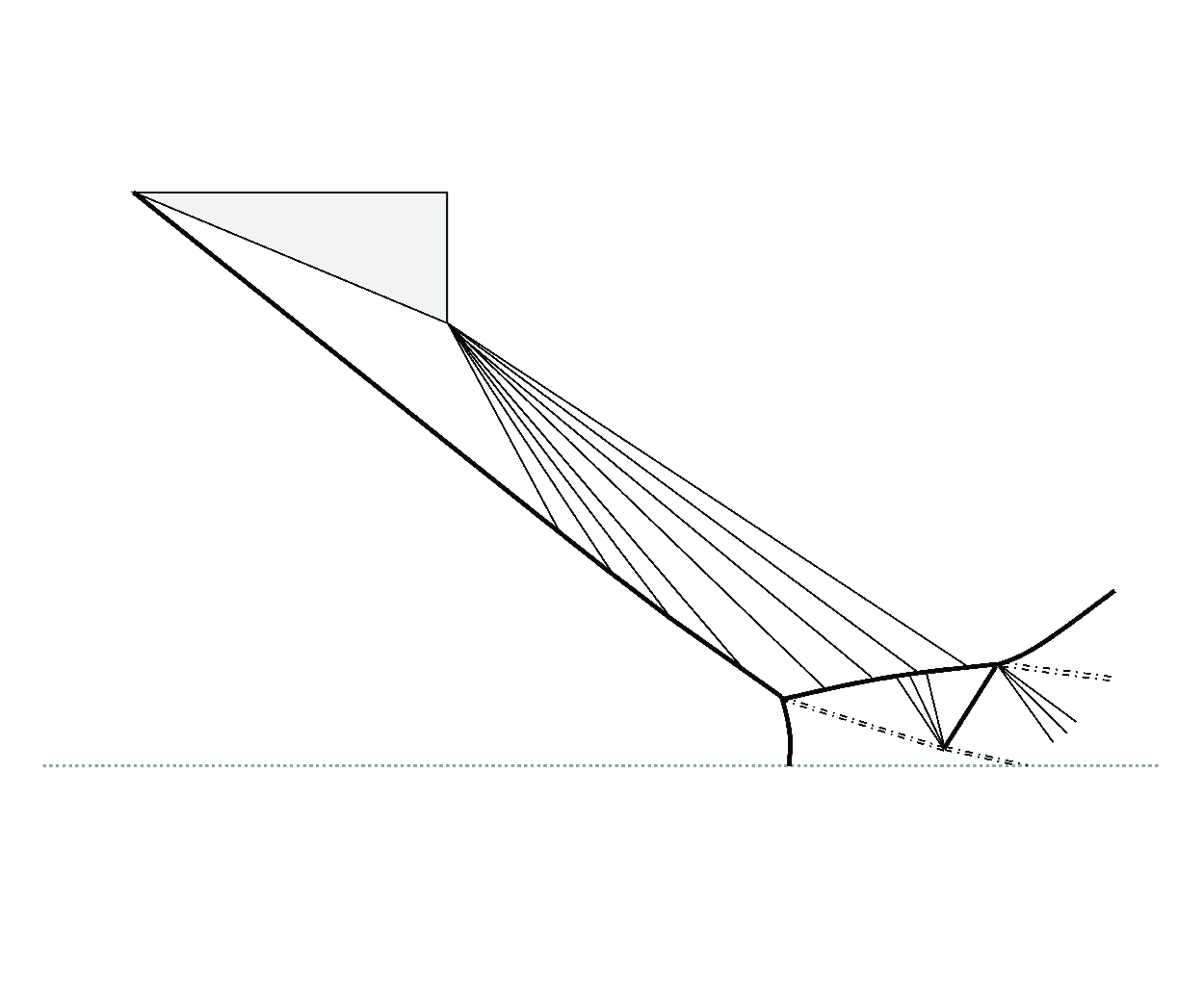
Figure 2. Schematic of steady MR with downstream expansion fan interference.
Figure 2 depicts the overall configuration for the steady MR with downstream expansion fan interference. Compared with the standard steady MR, the main difference in the flow field is that the expansion fan
 $R_{TE}$
interferes with the incident shock and covers the triple point. It is noteworthy that the interaction is also possible for RR. Before discussing the detailed flow structures, it is necessary to clarify the conditions for the configuration. Bai (Reference Bai2023) quantified the threshold for the interaction in the form of the relative trailing-edge height
$R_{TE}$
interferes with the incident shock and covers the triple point. It is noteworthy that the interaction is also possible for RR. Before discussing the detailed flow structures, it is necessary to clarify the conditions for the configuration. Bai (Reference Bai2023) quantified the threshold for the interaction in the form of the relative trailing-edge height
 $g=h/H_0$
and demonstrated its influence on the MR configuration and transition criteria. By assuming that the intersection point D between the leading edge of the expansion fan and the incident shock is on the reflection plane, i.e.
$g=h/H_0$
and demonstrated its influence on the MR configuration and transition criteria. By assuming that the intersection point D between the leading edge of the expansion fan and the incident shock is on the reflection plane, i.e.
 $y_D=0$
, the critical relative trailing-edge height
$y_D=0$
, the critical relative trailing-edge height
 $g_{max}$
is given by
$g_{max}$
is given by
 \begin{align} g_{max}=\frac {h_{max} / w}{h_{max} / w+\sin \theta _{w}}, \quad \frac {h_{max}}{w}=\frac {\cos \theta _{w} \tan \beta _{1}-\sin \theta _{w}}{\tan \left (\theta _{w}+\mu _{1}\right )-\tan \beta _{1}} \tan \left (\theta _{w}+\mu _{1}\right ). \end{align}
With
 $g\gt g_{max}$
, the downstream expansion fan interference occurs for RR. However, the condition
$g\gt g_{max}$
, the downstream expansion fan interference occurs for RR. However, the condition
 $g\gt g_{max}$
is insufficient for the interaction for MR, whose occurrence also depends on the Mach stem height (Li & Ben–Dor Reference Li and Ben-Dor1997). The trailing-edge height
$g\gt g_{max}$
is insufficient for the interaction for MR, whose occurrence also depends on the Mach stem height (Li & Ben–Dor Reference Li and Ben-Dor1997). The trailing-edge height
 $g$
represents a classical parameter to identify different shock reflection configurations (Vuillon et al. Reference Vuillon, Zeitoun and Ben-Dor1995; Li & Ben–Dor Reference Li and Ben-Dor1997).
$g$
represents a classical parameter to identify different shock reflection configurations (Vuillon et al. Reference Vuillon, Zeitoun and Ben-Dor1995; Li & Ben–Dor Reference Li and Ben-Dor1997).
Recently, Baby et al. (Reference Baby, Paramanantham and Rajesh2024) studied the RR
 $\rightarrow$
MR transition criterion from the perspective of the non-dimensional wedge length
$\rightarrow$
MR transition criterion from the perspective of the non-dimensional wedge length
 $\bar {w}=w/H_0$
, based on which they classified wedges as long or short. For a long wedge, the incident shock is free of expansion fan interference, representing the standard shock reflection. For a short wedge, the incident shock is exposed to the expansion fan, which is essentially the interfered configuration. Despite the valuable classification based on the wedge length, the corresponding thresholds are lacking. Based on the non-dimensional wedge length, we quantify the threshold for the interfered configuration, which also serves as the boundary between the long and short wedges according to the classification of Baby et al. (Reference Baby, Paramanantham and Rajesh2024). Similarly, the assumption of point D on the reflection plane gives
$\bar {w}=w/H_0$
, based on which they classified wedges as long or short. For a long wedge, the incident shock is free of expansion fan interference, representing the standard shock reflection. For a short wedge, the incident shock is exposed to the expansion fan, which is essentially the interfered configuration. Despite the valuable classification based on the wedge length, the corresponding thresholds are lacking. Based on the non-dimensional wedge length, we quantify the threshold for the interfered configuration, which also serves as the boundary between the long and short wedges according to the classification of Baby et al. (Reference Baby, Paramanantham and Rajesh2024). Similarly, the assumption of point D on the reflection plane gives
 \begin{align} \bar {w}_{min}=\frac {w_{min}}{H_0}=\frac {\sin {(\mu _1-\beta _1+\theta _w)}}{\sin {\beta _1}\sin {\mu _1}} . \end{align}
With
 $\bar {w}\lt \bar {w}_{min}$
, the interaction occurs for RR. Likewise, the condition does not account for the interaction for MR. There exists an inherent relation between the two thresholds defined by the trailing-edge height and wedge length, on which a further discussion is provided in appendix A.
$\bar {w}\lt \bar {w}_{min}$
, the interaction occurs for RR. Likewise, the condition does not account for the interaction for MR. There exists an inherent relation between the two thresholds defined by the trailing-edge height and wedge length, on which a further discussion is provided in appendix A.
2.1.1. Shock–expansion fan interaction
As a primary characteristic of the configuration, the interaction between the incident shock and expansion fan is of concern. As indicated in figure 2, the leading segment of the incident shock AD, free of the interference, is straight. However, the trailing segment of the incident shock DT deflects upwards when taking the extension line DR
 $^{\prime}$
as a reference. Such curvature comes from the interaction, similar to that for the reflected shock of standard MR. Notably, the proportion of the segment DT (i.e. the proportion of the incident shock exposed to the expansion fan) might serve as a decisive parameter for the interfered configurations. The effects of trailing-edge height (Bai Reference Bai2023) and wedge length (Baby et al. Reference Baby, Paramanantham and Rajesh2024) on the transition criteria might also be attributed to its variation.
$^{\prime}$
as a reference. Such curvature comes from the interaction, similar to that for the reflected shock of standard MR. Notably, the proportion of the segment DT (i.e. the proportion of the incident shock exposed to the expansion fan) might serve as a decisive parameter for the interfered configurations. The effects of trailing-edge height (Bai Reference Bai2023) and wedge length (Baby et al. Reference Baby, Paramanantham and Rajesh2024) on the transition criteria might also be attributed to its variation.
Based on the basic shock relation, the flow properties in the region (1) behind the straight segment AD can be obtained as
 \begin{align} \theta _w = \hat {\theta }_s(M_0,\beta _1), \quad M_1 = \hat {M}_s(M_0,\beta _1), \quad P_1 = P_0 \hat {P}_s(M_0,\beta _1) . \end{align}
We approximate the expansion fan as several discrete expansion waves, dividing the flow into several regions from (1) to (
 $N$
) as shown in the amplification in figure 2, where the flow properties can be obtained through the basic expansion wave relation,
$N$
) as shown in the amplification in figure 2, where the flow properties can be obtained through the basic expansion wave relation,
 \begin{align} v(M_N)-v(M_1)=\theta _w, \quad P_N = P_1 \hat {P}_e(M_1,M_N) . \end{align}
The angle of the expansion fan
 $\Delta$
is then given as
$\Delta$
is then given as
 \begin{align} \Delta = \theta _w+ \mu _1-\mu _N , \end{align}
where the Mach angles are
 $\mu _1 = \sin ^{-1}(1/M_1)\ \textrm{and}\ \mu _N = \sin ^{-1}(1/M_N)$
.
$\mu _1 = \sin ^{-1}(1/M_1)\ \textrm{and}\ \mu _N = \sin ^{-1}(1/M_N)$
.
We assume that the angle between two adjacent expansion waves equals
 $\delta$
. Thus, the number of divided regions is determined as
$\delta$
. Thus, the number of divided regions is determined as
 $N=\Delta /\delta +2$
. For the physical interaction between the incident shock and expansion waves, the interaction relation is established with the flow properties in the region (
$N=\Delta /\delta +2$
. For the physical interaction between the incident shock and expansion waves, the interaction relation is established with the flow properties in the region (
 $i$
) derived from those in the region (
$i$
) derived from those in the region (
 $i-1$
). Combining the angle relations with the shock wave relation, a set of recursive equations for the shock–expansion fan interaction is established as
$i-1$
). Combining the angle relations with the shock wave relation, a set of recursive equations for the shock–expansion fan interaction is established as
 \begin{align} \left . \begin{array}{c} \mu _i=\mu _{i-1}+{\rm d} \theta _i-\delta ,\quad {{\rm d}} \theta _i = v(M_i)-v(M_{i-1}), \quad \theta _i= \theta _{i-1}-{\rm d} \theta _i , \\[3pt] \theta _i = \hat {\theta }_s(M_0,\beta _i), \quad M_i = \hat {M}_s(M_0,\beta _i), \quad P_i = P_0 \hat {P}_s(M_0,\beta _i). \end{array} \right \} \end{align}
Since
 $M_0$
and
$M_0$
and
 $P_0$
are input parameters and
$P_0$
are input parameters and
 $\delta$
,
$\delta$
,
 $\mu _{i-1}$
,
$\mu _{i-1}$
,
 $M_{i-1}$
and
$M_{i-1}$
and
 $\theta _{i-1}$
are known, the above six-equation system is sufficient to solve for six unknowns
$\theta _{i-1}$
are known, the above six-equation system is sufficient to solve for six unknowns
 $\mu _i$
,
$\mu _i$
,
 $\mathrm {d}\theta _i$
,
$\mathrm {d}\theta _i$
,
 $M_i$
,
$M_i$
,
 $\theta _i$
,
$\theta _i$
,
 $\beta _i$
and
$\beta _i$
and
 $P_i$
.
$P_i$
.
Through the geometrical relationship, the coordinate for each intersection point between the expansion waves and the incident shock
 $\mathrm {D}_i(x_{D_i},y_{D_i})$
can be obtained,
$\mathrm {D}_i(x_{D_i},y_{D_i})$
can be obtained,
 \begin{align} \left . \begin{array}{c} \displaystyle y_{D_i}-y_{B} =-\tan \left (\mu _1+\theta _w-(i-1) \delta \right ) (x_{D_i}-x_{B}) \\[3pt] \displaystyle y_{D_i}-y_{D_{i-1}} =-\tan \beta _i (x_{D_i}-x_{D_{i-1}}) \end{array} \right \}, \end{align}
where the corresponding coordinates are
 $(w\cos {\theta _1}, H_0-w\sin {\theta _1})$
for point B and
$(w\cos {\theta _1}, H_0-w\sin {\theta _1})$
for point B and
 $(0, H_0)$
for point A.
$(0, H_0)$
for point A.
The complete shape of the incident shock and the flow parameters behind can then be solved via (2.3)–(2.7). As for the reflected shock, its interaction with the expansion fan is similar, except for the transmitted expansion waves generated. The analytical model for the reflected shock has been widely applied when investigating the standard MR, whose detailed derivation is omitted here and can be found in the literature (Li & Ben-Dor Reference Li and Ben-Dor1997; Gao & Wu Reference Gao and Wu2010).
2.1.2. Slipstream line
As shown in figure 3, the transmitted expansion waves
 $R_t$
travel downstream and intersect with the slip line, balancing the pressure between the two sides of the slip line. These generate reflected compression waves. Since the direction and intensity of the transmitted expansion waves
$R_t$
travel downstream and intersect with the slip line, balancing the pressure between the two sides of the slip line. These generate reflected compression waves. Since the direction and intensity of the transmitted expansion waves
 $R_t$
are already known through the analytical model for the reflected shock, the flow properties in the regions (b) and (c) (see figure 3
b) can be expressed based on the expansion wave and shock wave relations as
$R_t$
are already known through the analytical model for the reflected shock, the flow properties in the regions (b) and (c) (see figure 3
b) can be expressed based on the expansion wave and shock wave relations as
 \begin{align} v\left (M_{b}\right )-v\left (M_{a}\right )=\theta _{a b}, \quad P_{b}=P_{a} \hat {P}_{e}\left (M_{a}, M_{b}\right ), \\[-15pt] \nonumber \end{align}
 \begin{align} M_{c}=\hat {M}_{s}\left (M_{b}, \beta _{b}\right ), \quad \theta _{b c}=\hat {\theta }_{s}\left (M_{b}, \beta _{b}\right ), \quad P_{c}=P_{b} \hat {P}_{s}\left (M_{b}, \beta _{b}\right ) . \\[8pt] \nonumber \end{align}

Figure 3. (a) Schematic illustration of wave structures around the slip line and (b) amplification near the reflection point of the transmitted expansion wave.
However, we only have three expansions in (2.9) for four unknowns
 $M_c$
,
$M_c$
,
 $\theta _{bc}$
,
$\theta _{bc}$
,
 $\beta _b$
and
$\beta _b$
and
 $P_c$
. Thus, it is necessary to have a further discussion on the flow below the slip line. The subsonic region between the slip line and the reflection plane is usually treated as an isentropic quasi-one-dimensional flow. According to the isentropic flow theory, the relation between the local height of the slip line and the Mach stem height can be established, accompanied by the relation between the local pressure and the pressure right behind the Mach stem,
$P_c$
. Thus, it is necessary to have a further discussion on the flow below the slip line. The subsonic region between the slip line and the reflection plane is usually treated as an isentropic quasi-one-dimensional flow. According to the isentropic flow theory, the relation between the local height of the slip line and the Mach stem height can be established, accompanied by the relation between the local pressure and the pressure right behind the Mach stem,
 \begin{align} \frac {H_i}{H_T}=\frac {M_m}{M_i}\left (\frac {2+(\gamma -1) M_i^2}{2+(\gamma -1) M_m^2}\right )^{(\gamma +1)/(2(\gamma -1))}, \quad \frac {P_i}{P_m } = \left (\frac {2+(\gamma -1) M_m^2}{2+(\gamma -1) M_i^2}\right )^{\gamma /(\gamma -1)}, \end{align}
where
 $ M_m$
and
$ M_m$
and
 $P_m$
are the average Mach number and pressure just behind the Mach stem. Here
$P_m$
are the average Mach number and pressure just behind the Mach stem. Here
 $ H_i$
,
$ H_i$
,
 $M_i$
and
$M_i$
and
 $P_i$
refer to the local height of the slip line, local Mach number and local pressure.
$P_i$
refer to the local height of the slip line, local Mach number and local pressure.
With the two expressions, the relation between the local pressure
 $P_c$
and the local height of the slip line
$P_c$
and the local height of the slip line
 $H_{k+1}$
is obtained. The angle relation between the waves can be expressed as
$H_{k+1}$
is obtained. The angle relation between the waves can be expressed as
 \begin{align} \vartheta _c=\vartheta _a-\theta _{ab}-\theta _{bc} \end{align}
where
 $\vartheta$
represents the angle between the slip line and the horizontal line.
$\vartheta$
represents the angle between the slip line and the horizontal line.
With the above expressions, the flow properties around the slip line and its shape can be obtained.
2.1.3. Mach stem height
The iterative algorithm to obtain the height of the Mach stem is as follows.
Step 1. With the given free-stream Mach number
 $M_0$
, wedge angle
$M_0$
, wedge angle
 $\theta _w$
and non-dimensional wedge length
$\theta _w$
and non-dimensional wedge length
 $w/H_0$
, the shape of the incident shock can be obtained through the model proposed in § 2.1.1.
$w/H_0$
, the shape of the incident shock can be obtained through the model proposed in § 2.1.1.
Step 2. Set an initial guess for the Mach stem height
 $H_T$
to calculate the flow properties around the triple point, which are used to solve for the shapes of the reflected shock and slip line.
$H_T$
to calculate the flow properties around the triple point, which are used to solve for the shapes of the reflected shock and slip line.
Step 3. Since the subsonic flow below the slip line accelerates to sonic when the minimum height of the slip line is achieved, we examine whether the minimum height of the slip line
 $H_{min}$
equals the height of the sonic throat
$H_{min}$
equals the height of the sonic throat
 $H^*$
:
$H^*$
:
 \begin{align} \frac {H_T}{H^*}=\frac {1}{M_m} \left [\frac {2}{\gamma +1}\left (1+\frac {\gamma -1}{2}M^2_{m}\right )\right ]^{(\gamma +1)/({2(\gamma -1)})} . \end{align}
The above expression is deduced from the first equation in expression (2.10) by setting
 $M_i=1$
based on the one-dimensional-flow assumption. If
$M_i=1$
based on the one-dimensional-flow assumption. If
 $H_{min}=H^*$
, the Mach stem height is obtained; if
$H_{min}=H^*$
, the Mach stem height is obtained; if
 $H_{min} \neq H^*$
, the Mach stem height is updated back to Step 2. The process described above is repeated until a converged
$H_{min} \neq H^*$
, the Mach stem height is updated back to Step 2. The process described above is repeated until a converged
 $H_T$
is obtained.
$H_T$
is obtained.
2.2. Unsteady transition process
When investigating the time history of unsteady RR
 $\rightarrow$
MR transition, Li et al. (Reference Li, Gao and Wu2011) discovered and determined two major stages of the process: a multiple-interaction stage and a pure-MR stage, based on the evolution of the flow structures, clarifying the transition as an evolutionary rather than an abrupt process. The multiple-interaction stage comes up first, composed of a triple-shock structure, a type VI shock interaction and a shock–slip line interaction as shown in figure 4. The Mach stem
$\rightarrow$
MR transition, Li et al. (Reference Li, Gao and Wu2011) discovered and determined two major stages of the process: a multiple-interaction stage and a pure-MR stage, based on the evolution of the flow structures, clarifying the transition as an evolutionary rather than an abrupt process. The multiple-interaction stage comes up first, composed of a triple-shock structure, a type VI shock interaction and a shock–slip line interaction as shown in figure 4. The Mach stem
 $m$
grows locally at the reflection point, forming an incipient three-shock structure for the MR accompanied by the incident shock
$m$
grows locally at the reflection point, forming an incipient three-shock structure for the MR accompanied by the incident shock
 $i$
and reflected shock
$i$
and reflected shock
 $r$
. The reflected shock
$r$
. The reflected shock
 $r$
interferes with the reflected shock
$r$
interferes with the reflected shock
 $r^{\prime}$
of the original RR structure, which induces a transmitted shock
$r^{\prime}$
of the original RR structure, which induces a transmitted shock
 $r^{\prime\prime}$
, forming another triple-shock point F. At point Q, the transmitted shock
$r^{\prime\prime}$
, forming another triple-shock point F. At point Q, the transmitted shock
 $r^{\prime\prime}$
further intersects with the slip line
$r^{\prime\prime}$
further intersects with the slip line
 $s$
originated from the first triple point T, forming a shock–slip line interaction. Li et al. (Reference Li, Gao and Wu2011) provided a more detailed description of the flow structures, including the expansion fans
$s$
originated from the first triple point T, forming a shock–slip line interaction. Li et al. (Reference Li, Gao and Wu2011) provided a more detailed description of the flow structures, including the expansion fans
 $R_Q$
and
$R_Q$
and
 $R_F$
induced by the two interactions. As the flow structures further evolve, the sonic throat is formed gradually, indicating that the transition enters the pure-MR stage, for which Mouton & Hornung (Reference Mouton and Hornung2007) provided a detailed analysis. At the moment, the flow structures are quite similar to that of steady MR as shown in figure 2, except for the upstream-moving triple point T along the incident shock
$R_F$
induced by the two interactions. As the flow structures further evolve, the sonic throat is formed gradually, indicating that the transition enters the pure-MR stage, for which Mouton & Hornung (Reference Mouton and Hornung2007) provided a detailed analysis. At the moment, the flow structures are quite similar to that of steady MR as shown in figure 2, except for the upstream-moving triple point T along the incident shock
 $i$
. Despite the simplicity of the configuration, the pure-MR stage occupies most of the transition process. To clarify the sequence of the two stages, the multiple-interaction and pure-MR stages are called Stage I and Stage II.
$i$
. Despite the simplicity of the configuration, the pure-MR stage occupies most of the transition process. To clarify the sequence of the two stages, the multiple-interaction and pure-MR stages are called Stage I and Stage II.

Figure 4. Schematic illustration of the multiple-interaction stage during the RR
 $\rightarrow$
MR transition with downstream expansion fan interference.
$\rightarrow$
MR transition with downstream expansion fan interference.
2.2.1. Moving triple point
To establish the theoretical model describing the unsteady transition process, the steady three-shock theory is assumed to be valid when the reference frame is attached to the moving triple point. According to the assumption, the pure-MR stage can be evaluated through the steady MR model (Mouton & Hornung Reference Mouton and Hornung2007). Thus, only the modelling of the transition process during the multiple-interaction stage is discussed here. Based on the basic wave relations and the reference frame attached to the moving triple point, the three-shock relation around the moving triple point can be reconstructed.
The triple point moves upstream along the incident shock, which remains stationary even in the fixed frame during the transition process. Thus, the model for the steady incident shock depicted in § 2.1.1 can still be applied. The flow properties in the region (1) in figure 4 around the triple point can be expressed as
 \begin{align} \left .\begin{array}{r@{\quad}l} M_{1}^{T}=\hat {M}_{s}\left (M_{0}, \beta _{1}^T\right ), & P_{1}^{T}=P_{0} \hat {M}_{s}\left (M_{0}, \beta _{1}^T\right ), \\[3pt] \theta _{1}^{T}=\hat {\theta }_{s}\left (M_{0}, \beta _{1}^T\right ), & a_{1}=a_{0} \hat {A}_{s}\left (M_{0}, \beta _{1}^T\right ),\end{array}\right \} \end{align}
where the superscript
 $T$
denotes the quantities near the triple point T.
$T$
denotes the quantities near the triple point T.
For the flow properties in region (2), the relative parameters at the moving frame are applied, considering the movement of reflected shock with the triple point, which can be expressed as
 \begin{align} \left .\begin{array}{r@{\quad}r} \widetilde {M_{2}^{T}}=\hat {M_{s}}\left (\widetilde {M_{1}^{T}}, \widetilde {\beta _{2}^{T}}\right ), & P_{2}^{T}=P_{1}^{T} \hat {M}_{s}\left (\widetilde {M_{1}^{T}}, \widetilde {\beta _{2}^{T}}\right ), \\[6pt] \widetilde {\theta _{2}^{T}}=\hat {\theta }_{s}\left (\widetilde {M}_{1}^{T}, \widetilde {\beta _{2}^{T}}\right ), & a_{2}=a_{1} \hat {A}_{s}\left (\widetilde {M_{1}^{T}}, \widetilde {\beta _{2}^{T}}\right ),\end{array}\right \} \end{align}
where the hat
 $\sim$
denotes the relative quantities in the reference frame attached to the moving triple point. The detailed description of the relations between the relative flow quantities and absolute flow quantities can be found in Li et al. (Reference Li, Gao and Wu2011).
$\sim$
denotes the relative quantities in the reference frame attached to the moving triple point. The detailed description of the relations between the relative flow quantities and absolute flow quantities can be found in Li et al. (Reference Li, Gao and Wu2011).
Similarly, the flow properties in region (3) behind the Mach stem can be expressed as
 \begin{align} \left .\begin{array}{c} \widetilde {M_{3}^{T}}=\hat {M}_{s}\left (\widetilde {M_{0}^{T}}, \widetilde {\beta _{3}^{T}}\right ), \quad P_{3}^{T}=P_{0} \hat {P}_{s}\left (\widetilde {M_{0}^{T}}, \widetilde {\beta _{3}^{T}}\right ), \quad \rho _{3}=\rho _{0} \hat {\rho }_{s}\left (\widetilde {M_{0}^{T}}, \widetilde {\beta _{3}^{T}}\right ) \\[6pt] \widetilde {\theta _{3}^{T}}=\hat {\theta }_{s}\left (\widetilde {M_{0}^{T}}, \widetilde {\beta _{3}^{T}}\right ), \quad a_{3}=a_{0} \hat {A}_{s}\left (\widetilde {M_{0}^{T}}, \widetilde {\beta _{3}^{T}}\right ).\end{array}\right \} \end{align}
Across the slip line, the deflection angle and pressure satisfy
 \begin{align} \theta _{3}^{T}=\theta _{1}^{T}-\theta _{2}^{T},\quad P_{2}^{T}=P_{3}^{T}. \end{align}
The expressions (2.13)–(2.16) represent the triple-shock relation in the reference frame attached to the moving triple point, which can be reduced to the classic three-shock relation for steady MR in the case of a stationary triple point
 $V_T=0$
. However, it is still necessary to determine the velocity of the triple point
$V_T=0$
. However, it is still necessary to determine the velocity of the triple point
 $V_T$
to solve the above relations and obtain the flow properties around the moving triple point.
$V_T$
to solve the above relations and obtain the flow properties around the moving triple point.
2.2.2. Triple-point velocity
The triple-point velocity
 $V_T$
is the key parameter of the RR
$V_T$
is the key parameter of the RR
 $\rightarrow$
MR transition process, reflecting the time evolution of the flow structures. Due to the significant differences in the flow characteristics, the velocities of the triple point in the multiple-interaction stage (Stage I) and pure-MR stage (Stage II) should be determined differently.
$\rightarrow$
MR transition process, reflecting the time evolution of the flow structures. Due to the significant differences in the flow characteristics, the velocities of the triple point in the multiple-interaction stage (Stage I) and pure-MR stage (Stage II) should be determined differently.
For the multiple-interaction stage, Li et al. (Reference Li, Gao and Wu2011) determined the velocity of the triple point based on the mass conservation for the fluid inside the triangle control volume TRN (indicated in figure 4). Since the mass flow rate across the Mach stem accounts for the mass increase in the control volume TRN, the mass conservation can be expressed as
 \begin{align} \rho _{0} H_{T}\left (M_{0} a_{0}+V_{T} \cos \beta _{1}^{T}\right ) \approx \frac {\mathrm {{\rm d}}\left (\rho _{3} S_\mathit{TRN}\right )}{\mathrm {{\rm d}} t}. \end{align}
Assuming the reflected shock and slip line to be straight, the area of the control volume can be approximated as
 $ S_\mathit{TRN}=H_{T}^{2}/2\tan \theta _3^T$
. Considering
$ S_\mathit{TRN}=H_{T}^{2}/2\tan \theta _3^T$
. Considering
 $\mathrm {{\rm d}}H_T/\mathrm {{\rm d}}t\approx V_T\sin \beta _1^T$
, the velocity of the triple point can be obtained as
$\mathrm {{\rm d}}H_T/\mathrm {{\rm d}}t\approx V_T\sin \beta _1^T$
, the velocity of the triple point can be obtained as
 \begin{align} V_{T}=\frac {\rho _{0} M_{0} a_{0} \tan \theta _{3}^{T}}{\rho _{3} \sin \beta _{1}^{T}-\rho _{0} \tan \theta _{3}^{T} \cos \beta _{1}^{T}}. \end{align}
For the pure-MR stage, the downstream flow field behind the Mach stem is well developed, and a pure MR structure is obtained. When the reference frame is attached to the moving triple point, the steady MR theoretical model can describe the moving triple point during the pure-MR stage (Mouton & Hornung Reference Mouton and Hornung2007; Li et al. Reference Li, Gao and Wu2011). By introducing the triple-point velocity
 $V_T$
and reconstructing the three-shock relation, the corresponding Mach stem height can be calculated through the steady MR model depicted in Figure 2, which yields the relation between the Mach stem height and triple-point velocity.
$V_T$
and reconstructing the three-shock relation, the corresponding Mach stem height can be calculated through the steady MR model depicted in Figure 2, which yields the relation between the Mach stem height and triple-point velocity.
3. Results and discussion
3.1. Flow structure for steady MR
3.1.1. Overall configuration
The overall structure of the flow field for the steady MR with downstream expansion fan interference is investigated. Figure 5 compares the MR structures predicted by the analytical model (denoted by red solid lines) and the Mach number contours obtained through numerical simulation (denoted by black dotted lines), which exhibit good agreement. The shapes of the incident shock, reflected shock and slip line are consistent with the simulation. Therefore, the analytical model is capable of making effective predictions for the MR structures.

Figure 5. Comparisons of the analytical configuration with the numerical results for MR with downstream expansion fan interference (
 $M_0=3.65, \theta _w=30^{\circ }, w/H_0=0.6$
).
$M_0=3.65, \theta _w=30^{\circ }, w/H_0=0.6$
).
At first glance, the configuration for interfered MRs shows no difference from standard MRs, except for the location of the expansion fan relative to the shock structure. The shock–expansion fan interaction will introduce curvature to the shock, which is, however, hard to identify through the overall structure. Thus, a detailed analysis of the shapes of the incident shock, reflection shock and slip line is necessary.
3.1.2. Mach stem height

Figure 6. Comparisons of the analytical Mach stem height with the numerical results for MRs with downstream expansion fan interference: (a)
 $\theta _w=30^{\circ }, w/H_0=0.6$
and (b)
$\theta _w=30^{\circ }, w/H_0=0.6$
and (b)
 $\theta _w=28^{\circ }, w/H_0=0.7$
.
$\theta _w=28^{\circ }, w/H_0=0.7$
.
As a specific flow structure for MRs, the Mach stem determines the overall configuration of the flow field, whose height serves as an indicator reflecting the shapes of the slip line and the shock waves. Figure 6 shows good agreement between the Mach stem height predicted by the analytical model and numerical results.
It is noted that the Mach stem heights are relatively small, compared with the standard MRs. This is because the expansion fan weakens the incident shock wave and deflects the slip line downwards, accelerating the formation of the sonic throat. The flow structure stabilizes rapidly, resulting in generally small Mach stem heights. The underlying mechanism will be illustrated in the following discussion on the unsteady RR
 $\rightarrow$
MR transition process.
$\rightarrow$
MR transition process.
3.1.3. Shape of the incident shock, reflected shock and slip line

Figure 7. Shape, slope and curvature of the analytical (a) incident shock wave, (b) reflected shock wave and (c) slip line (
 $M_0=3.65, \theta _w=30^{\circ }, w/H_0=0.6$
).
$M_0=3.65, \theta _w=30^{\circ }, w/H_0=0.6$
).
Figure 7 shows the shape of the incident shock wave, reflected shock wave and slip line obtained through the analytical model for
 $M_0=3.65, \theta _w=30^{\circ }\ \textrm{and}\ w/H_0=0.6$
. For the incident shock, the shock–expansion fan interaction weakens its strength. Thus, as shown in figure 7(a), the incident shock remains straight initially and begins to deflect away from the reflection plane at the intersection point D. Correspondingly, the local incident shock angle decreases, indicated by the reduction in the absolute value of the slope of the incident shock. As shown in figure 7(b), the reflected shock deflects towards the wedge smoothly, whose slope increases slightly, until its intersection point E with the trailing edge of the expansion fan. After the point E, the slope remains constant, and the curvature decreases to zero.
$M_0=3.65, \theta _w=30^{\circ }\ \textrm{and}\ w/H_0=0.6$
. For the incident shock, the shock–expansion fan interaction weakens its strength. Thus, as shown in figure 7(a), the incident shock remains straight initially and begins to deflect away from the reflection plane at the intersection point D. Correspondingly, the local incident shock angle decreases, indicated by the reduction in the absolute value of the slope of the incident shock. As shown in figure 7(b), the reflected shock deflects towards the wedge smoothly, whose slope increases slightly, until its intersection point E with the trailing edge of the expansion fan. After the point E, the slope remains constant, and the curvature decreases to zero.
Figure 7(c) provides the slope and curvature of the slip line, whose features are significantly different from those of standard MRs. For the standard MRs (Gao & Wu Reference Gao and Wu2010; Bai & Wu Reference Bai and Wu2017), there always exists an inflection point I between the triple point T and the sonic throat S, which is also the intersection point between the leading transmitted expansion wave and the slip line, as shown in figure 8(a). At this point, the curvature of the slip line jumps abruptly from negative to positive. Ahead of the point, the leading portion of the slip line TI is not influenced by the transmitted expansion waves
 $R_t$
. With the deflection of the slip line towards the reflection plane, the subsonic stream tube below converges, accelerating the flow and decreasing the pressure. To balance the pressure between the two sides of the slip line, additional expansion waves
$R_t$
. With the deflection of the slip line towards the reflection plane, the subsonic stream tube below converges, accelerating the flow and decreasing the pressure. To balance the pressure between the two sides of the slip line, additional expansion waves
 $R_S$
are induced above this portion of the slip line. For the trailing portion of the slip line IS, the balance of the pressure is achieved through the transmitted expansion waves
$R_S$
are induced above this portion of the slip line. For the trailing portion of the slip line IS, the balance of the pressure is achieved through the transmitted expansion waves
 $R_t$
and their reflection. Thus, the slip line is convex at portion TI and then concave at portion IS, accounting for the sudden change in its curvature.
$R_t$
and their reflection. Thus, the slip line is convex at portion TI and then concave at portion IS, accounting for the sudden change in its curvature.

Figure 8. Schematic of wave structures around the slip line with (a) no wave interference and (b) expansion fan interference.
However, for the MR with downstream expansion fan interference, the transmitted expansion waves
 $R_t$
fully cover the slip line TS as shown in figure 8(b). The equilibrium condition for the pressure on both sides of the slip line can be achieved through the transmitted expansion waves and their reflection, and the slip line no longer induces additional expansion waves. Thus, no inflection point is observed in figure 7(c), where the slope of the slip line increases smoothly and reaches zero at the sonic throat S. Furthermore, due to the persistently positive curvature, the slip line achieves its minimal height more rapidly, accelerating the formation of the sonic throat. This also accounts for the lower Mach stem height for the interference MR.
$R_t$
fully cover the slip line TS as shown in figure 8(b). The equilibrium condition for the pressure on both sides of the slip line can be achieved through the transmitted expansion waves and their reflection, and the slip line no longer induces additional expansion waves. Thus, no inflection point is observed in figure 7(c), where the slope of the slip line increases smoothly and reaches zero at the sonic throat S. Furthermore, due to the persistently positive curvature, the slip line achieves its minimal height more rapidly, accelerating the formation of the sonic throat. This also accounts for the lower Mach stem height for the interference MR.
3.2.
Flow structures for RR
 $\rightarrow$
MR transition
$\rightarrow$
MR transition


Figure 9. Instantaneous representations of the Mach contours for the RR
 $\rightarrow$
MR transition interfered by the downstream expansion fan induced by the trailing edge of the wedge (
$\rightarrow$
MR transition interfered by the downstream expansion fan induced by the trailing edge of the wedge (
 $M_0=3.65, \theta _w=30^{\circ }, w/H_0=0.6$
).
$M_0=3.65, \theta _w=30^{\circ }, w/H_0=0.6$
).
The time evolution of the flow structures during the RR
 $\rightarrow$
MR transition is investigated in this subsection. Figure 9 describes the RR
$\rightarrow$
MR transition is investigated in this subsection. Figure 9 describes the RR
 $\rightarrow$
MR transition process with downstream expansion fan interference in the dual-solution domain in the form of the Mach number contours at a series of moments for
$\rightarrow$
MR transition process with downstream expansion fan interference in the dual-solution domain in the form of the Mach number contours at a series of moments for
 $M_0=3.65$
,
$M_0=3.65$
,
 $\theta _w=30^{\circ }$
and
$\theta _w=30^{\circ }$
and
 $w/H_0=0.6$
. The transition is triggered by a velocity perturbation near the reflection plane, whose introduction is described in appendix B, accompanied with detailed numerical set-ups. The instant when the perturbation reaches the reflection point of the RR structure is defined as
$w/H_0=0.6$
. The transition is triggered by a velocity perturbation near the reflection plane, whose introduction is described in appendix B, accompanied with detailed numerical set-ups. The instant when the perturbation reaches the reflection point of the RR structure is defined as
 $t=0$
as shown in figure 9(a). The continuous disturbance induces a local Mach stem at the reflection point, forming a three-shock structure as shown in figure 9(b). As the Mach stem evolves, the newly formed reflected shock at the triple point intersects with the original reflected shock of the RR structure, forming a second triple point, as shown in figure 9(c–f). The second triple point travels downstream along the reflected shock of the RR structure until it dissipates. The evolution of the flow structures agrees with that observed by Kudryavtsev et al. (Reference Kudryavtsev, Khotyanovsky, Ivanov, Hadjadj and Vandromme2002), which was defined by Li et al. (Reference Li, Gao and Wu2011) as a multiple-interaction stage (Stage I). With the further growth of the Mach stem, the slip line no longer intersects with the reflection plane, forming a sonic throat as shown figure 9(g). At this moment, the shock reflection structure is similar to that of a steady MR, thus defined as pure unsteady MR stage (Stage II) (Li et al. Reference Li, Gao and Wu2011). The flow structures, including the Mach stem, reflected shock and slip line, further evolve until they stabilize as shown in figure 9(h).
$t=0$
as shown in figure 9(a). The continuous disturbance induces a local Mach stem at the reflection point, forming a three-shock structure as shown in figure 9(b). As the Mach stem evolves, the newly formed reflected shock at the triple point intersects with the original reflected shock of the RR structure, forming a second triple point, as shown in figure 9(c–f). The second triple point travels downstream along the reflected shock of the RR structure until it dissipates. The evolution of the flow structures agrees with that observed by Kudryavtsev et al. (Reference Kudryavtsev, Khotyanovsky, Ivanov, Hadjadj and Vandromme2002), which was defined by Li et al. (Reference Li, Gao and Wu2011) as a multiple-interaction stage (Stage I). With the further growth of the Mach stem, the slip line no longer intersects with the reflection plane, forming a sonic throat as shown figure 9(g). At this moment, the shock reflection structure is similar to that of a steady MR, thus defined as pure unsteady MR stage (Stage II) (Li et al. Reference Li, Gao and Wu2011). The flow structures, including the Mach stem, reflected shock and slip line, further evolve until they stabilize as shown in figure 9(h).

Figure 10. Evolution of the triple point for the RR
 $\rightarrow$
MR transition interfered by the downstream expansion fan induced by the trailing edge of the wedge (
$\rightarrow$
MR transition interfered by the downstream expansion fan induced by the trailing edge of the wedge (
 $M_0=3.65, \theta _w=30^{\circ }, w/H_0=0.6$
). (a) Mach stem height as a function of time; (b) triple-point velocity as a function of Mach stem height; (c) triple-point velocity as a function of time. ——, analytical model - - - -, numerical simulation.
$M_0=3.65, \theta _w=30^{\circ }, w/H_0=0.6$
). (a) Mach stem height as a function of time; (b) triple-point velocity as a function of Mach stem height; (c) triple-point velocity as a function of time. ——, analytical model - - - -, numerical simulation.
Figure 10 illustrates the evolution of the triple point during the transition process, which shows considerable agreement between the analytical and numerical results. Figure 10(a) indicates the development of the Mach stem, whose growth is rapid at the outset but slows down gradually. Figure 10(b) describes the relationship between the triple-point velocity and the Mach stem height, which exhibits a turning point, indicating the transition from the multiple-interaction stage (Stage I) into the pure-MR stage (Stage II). The process agrees with the Mach contours in figure 9. Figure 10(c) displays the variation of the triple-point velocity with time. During the multiple-interaction stage, the slip line intersects with the reflection plane, enclosing the downstream area behind the Mach stem. The flow mass across the Mach stem contributes to the enlargement of the downstream region, resulting in a rapid development of the Mach stem and corresponding higher triple-point velocity. During the pure-MR stage, the slip line departs from the reflection plane. Most of the flow mass across the Mach stem travels downstream through the throat, leaving a small portion of the flow mass to promote the growth of the Mach stem, which results in the rapid decrease of the triple-point velocity. Although the duration of the multiple-interaction stage (Stage I) is significantly shorter than that for the pure-MR stage (Stage II), the multiple-interaction stage contributes to a great part of the development of the Mach stem height. In the current case, the Mach stem height growth during the multiple-interaction stage occupies nearly half of the eventual Mach stem height.
Although the overall characteristics for the evolution of the triple point are similar to those for the standard RR
 $\rightarrow$
MR transition (Li et al. Reference Li, Gao and Wu2011), the triple-point velocity exhibits an increasing tendency during the multiple-interaction stage, which is, however, a constant for the no-wave-interference case. The feature implies the impact of the downstream expansion fan interference on the RR
$\rightarrow$
MR transition (Li et al. Reference Li, Gao and Wu2011), the triple-point velocity exhibits an increasing tendency during the multiple-interaction stage, which is, however, a constant for the no-wave-interference case. The feature implies the impact of the downstream expansion fan interference on the RR
 $\rightarrow$
MR transition, which is worth further discussion.
$\rightarrow$
MR transition, which is worth further discussion.
3.3. Evolution mechanism of Mach stem with wave interference
When investigating the transition of curved shock reflection, which represents a configuration with downstream compression wave interference, Zhang et al. (Reference Zhang, Xu, Shi, Zhu and You2023) observed decreasing rather than constant triple-point velocity during the multiple-interaction stage (Stage I), which stemmed from the weakening of the incident shock wave. An explanation for the decline was given based on the variation of the control volume. Conversely, the velocity of the triple point increases during the multiple-interaction stage with downstream expansion fan interference in the present case.
The schematics for the evolution of the Mach stem for the three wave-interference cases are given in figure 11, in which the detailed shock structures of the triple point during the transition process are also plotted. For the no-wave-interference case shown in figure 11(a), the triple point moves upstream along the straight incident shock with the growth of the Mach stem, which is essentially a self-similar process for the shock structures (
 $\beta =\beta ^{\prime}$
), accounting for the constant velocity of the triple point during the multiple-interaction stage. However, the wave interference introduces curvature to the incident shock, interrupting the self-similar process. For the compression-wave-interference case shown in figure 11(b), the incident shock deflects towards the reflection plane, resulting in a larger incident shock angle at the reflection point (
$\beta =\beta ^{\prime}$
), accounting for the constant velocity of the triple point during the multiple-interaction stage. However, the wave interference introduces curvature to the incident shock, interrupting the self-similar process. For the compression-wave-interference case shown in figure 11(b), the incident shock deflects towards the reflection plane, resulting in a larger incident shock angle at the reflection point (
 $\beta \gt \beta ^{\prime}$
). With the development of the Mach stem, the triple point moves upstream along the curved incident shock, accompanied by the decrease of the incident shock angle at the triple point with
$\beta \gt \beta ^{\prime}$
). With the development of the Mach stem, the triple point moves upstream along the curved incident shock, accompanied by the decrease of the incident shock angle at the triple point with
 $\beta$
approaching
$\beta$
approaching
 $\beta ^{\prime}$
, corresponding to the configuration investigated by Zhang et al. (Reference Zhang, Xu, Shi, Zhu and You2023). Conversely, for the expansion fan interference shown in figure 11(c), the incident shock deflects away from the reflection plane (
$\beta ^{\prime}$
, corresponding to the configuration investigated by Zhang et al. (Reference Zhang, Xu, Shi, Zhu and You2023). Conversely, for the expansion fan interference shown in figure 11(c), the incident shock deflects away from the reflection plane (
 $\beta \lt \beta ^{\prime}$
), increasing the incident shock angle during the multiple-interaction stage.
$\beta \lt \beta ^{\prime}$
), increasing the incident shock angle during the multiple-interaction stage.
To demonstrate the impact of such curvature on the evolution of the Mach stem, it is necessary to discuss the relationship between the incident shock angle and the triple-point velocity. Figure 12 shows the variation of the triple-point velocity with the incident shock angle for the no-wave-interference case, indicating that a higher incident shock angle results in a higher triple-point velocity, which exhibits an approximately linear relationship. The tendency accounts for the variation in the velocity when the triple point travels upstream along the curved incident shock for the wave-interference cases, where the incident shock angle at the triple point varies during the process of
 $\beta$
approaching
$\beta$
approaching
 $\beta ^{\prime}$
. Thus, it can be concluded that the wave interference brings curvature to the incident shock, which deflects towards the reflection plane for the compression wave interference but in the opposite direction for the expansion fan interference. During the multiple-interaction stage, the shock angle at the triple-point changes when moving upstream along the curved incident shock, resulting in the varying triple-point velocity, whose tendency depends on the shock curvature.
$\beta ^{\prime}$
. Thus, it can be concluded that the wave interference brings curvature to the incident shock, which deflects towards the reflection plane for the compression wave interference but in the opposite direction for the expansion fan interference. During the multiple-interaction stage, the shock angle at the triple-point changes when moving upstream along the curved incident shock, resulting in the varying triple-point velocity, whose tendency depends on the shock curvature.

Figure 11. Schematics for the evolution of the Mach stem in terms of triple-point velocity as a function of Mach stem height with (a) no wave interference, (b) compression wave interference and (c) expansion fan interference.

Figure 12. Triple-point velocity as a function of incident shock angle for no wave interference.
It is noteworthy that the above discussion is limited to downstream wave interference, usually induced by a wedge with a non-standard shape or length. Upstream wave interference, which may occur over a reflection plane with a turning point (Hillier Reference Hillier2007; Yao, Li & Wu Reference Yao, Li and Wu2013), will result in an opposite direction of the curved incident shock to those with downstream interference, which will likely reverse the tendency of the triple-point velocity during the evolution of the Mach stem summarized above. A further investigation of the RR
 $\rightarrow$
MR transition with upstream wave interference will be a valuable extension of the present work in the future.
$\rightarrow$
MR transition with upstream wave interference will be a valuable extension of the present work in the future.
4. Conclusions
In this paper, the reflection of shock waves with downstream expansion fan interference, originating from the trailing edge of the wedge, in two-dimensional, inviscid flow is investigated numerically and analytically, including the steady MR and the unsteady RR
 $\rightarrow$
MR transition. The threshold of the configuration is quantified in the form of wedge length, which also serves as the boundary between the long and short wedges according to the classification by Baby et al. (Reference Baby, Paramanantham and Rajesh2024).
$\rightarrow$
MR transition. The threshold of the configuration is quantified in the form of wedge length, which also serves as the boundary between the long and short wedges according to the classification by Baby et al. (Reference Baby, Paramanantham and Rajesh2024).
For the steady MR, the weakening of the incident shock by the expansion fan interference accelerates the formation of the sonic throat, resulting in a generally small Mach stem height. Due to the exposure of the triple point to the expansion fan, the slip line is fully covered by the transmitted expansion waves. Thus, the slip line no longer induces additional expansion waves to balance the pressure between both sides, which eliminates the inflection point on the slip line, accounting for its smoothly increasing slope.
For the RR
 $\rightarrow$
MR transition, the multiple-interaction (Stage I) and pure-MR (Stage II) stages are observed as expected. The triple-point velocity during the multiple-interaction stage exhibits an increasing tendency, which is, however, a constant for the no-wave-interference case. Reviewing the previous work of Li et al. (Reference Li, Gao and Wu2011) and Zhang et al. (Reference Zhang, Xu, Shi, Zhu and You2023), the impact of wave interference on the triple-point velocity during the multiple-interaction stage is summarized: for no wave interference, the triple-point velocity remains constant; for compression wave interference, the triple-point velocity decreases; for expansion fan interference, the triple-point velocity increases. Based on the shock structures of the triple-point, it appears that the different tendencies in the triple-point velocity arise from the curvature of the incident shock brought by the wave interference. During the multiple-interaction stage, the triple-point moves upstream along the curved incident shock, where the incident shock angle changes according to the curvature, resulting in the variation of the triple-point velocity.
$\rightarrow$
MR transition, the multiple-interaction (Stage I) and pure-MR (Stage II) stages are observed as expected. The triple-point velocity during the multiple-interaction stage exhibits an increasing tendency, which is, however, a constant for the no-wave-interference case. Reviewing the previous work of Li et al. (Reference Li, Gao and Wu2011) and Zhang et al. (Reference Zhang, Xu, Shi, Zhu and You2023), the impact of wave interference on the triple-point velocity during the multiple-interaction stage is summarized: for no wave interference, the triple-point velocity remains constant; for compression wave interference, the triple-point velocity decreases; for expansion fan interference, the triple-point velocity increases. Based on the shock structures of the triple-point, it appears that the different tendencies in the triple-point velocity arise from the curvature of the incident shock brought by the wave interference. During the multiple-interaction stage, the triple-point moves upstream along the curved incident shock, where the incident shock angle changes according to the curvature, resulting in the variation of the triple-point velocity.
Acknowledgements
The authors would like to thank E. Huang and H. Zhang for the enlightening discussions and suggestions regarding this work.
Funding
This research work is mainly supported by the National Natural Science Foundation of China under grant no. 12372233, and partly supported by the Science Fund of NPU-Duke China Seeds Program (119003067) and the 111 Project of China (B17037).
Declaration of interests
The authors report no conflict of interest.
Appendix A. Threshold for shock reflection configurations based on wedge length

Figure 13. (a) Lower limit and (b) upper limit for the standard RR configuration in terms of wedge length.
Li & Ben-Dor (Reference Li and Ben-Dor1997) proposed the upper limit and lower limit of the trailing edge height
 $h$
for the standard steady shock reflection configuration. The upper limit
$h$
for the standard steady shock reflection configuration. The upper limit
 $h_{max}$
is determined by assuming that the leading edge of the expansion fan impinges on the reflection point as shown in figure 13(a). The lower limit
$h_{max}$
is determined by assuming that the leading edge of the expansion fan impinges on the reflection point as shown in figure 13(a). The lower limit
 $h_{min}$
is determined by assuming that the reflected shock touches the trailing edge of the wedge figure 13(b). Through the geometrical relations among the shock angle, wedge angle and Mach angle, the two limits can then be obtained as
$h_{min}$
is determined by assuming that the reflected shock touches the trailing edge of the wedge figure 13(b). Through the geometrical relations among the shock angle, wedge angle and Mach angle, the two limits can then be obtained as
 \begin{align} h_{max}=\frac {w\sin (\mu _1+\theta _w)\sin (\beta _1-\theta _w)}{\sin (\mu _1+\theta _w-\beta _1)}, \quad h_{min}=\frac {w\sin (\beta _2-\theta _w)\sin (\beta _1-\theta _w)}{\sin (\beta _1+\beta _2-\theta _w)} . \end{align}
When
 $h\gt h_{max}$
, the trailing-edge height is so large that the expansion fan intersects the incident shock, forming the shock reflection with downstream expansion fan interference. When
$h\gt h_{max}$
, the trailing-edge height is so large that the expansion fan intersects the incident shock, forming the shock reflection with downstream expansion fan interference. When
 $h\lt h_{min}$
, the trailing-edge height is so small that the reflected shock impinges on the wedge, forming a secondary shock reflection on the wedge wall.
$h\lt h_{min}$
, the trailing-edge height is so small that the reflected shock impinges on the wedge, forming a secondary shock reflection on the wedge wall.
From the perspective of wedge length, the upper limit and lower limit for the shock reflection configuration can also be determined:
 \begin{align} w_{min}=\frac {H_0\sin (\mu _1-\beta _1+\theta _w)}{\sin (\beta _1)\sin (\mu _1)}, \quad w_{max}=\frac {2H_0\sin (\beta _1+\beta _2-\theta _w)}{\cos (\beta _1-\beta _2)-\cos (\beta _1+\beta _2)} . \end{align}
For
 $w\lt w_{min}$
, the wedge can be defined as a ‘short’ wedge, forming a shock reflection with downstream expansion fan interference; for
$w\lt w_{min}$
, the wedge can be defined as a ‘short’ wedge, forming a shock reflection with downstream expansion fan interference; for
 $w_{min}\lt w\lt w_{max}$
, the wedge can be defined as a ‘standard’ wedge, forming a classical shock reflection. For
$w_{min}\lt w\lt w_{max}$
, the wedge can be defined as a ‘standard’ wedge, forming a classical shock reflection. For
 $w\gt w_{max}$
, the wedge can be defined as a ‘long’ wedge, forming a secondary shock reflection on the wedge surface. Due to the introduction of the upper limit, the definition here differs from that proposed by Baby et al. (Reference Baby, Paramanantham and Rajesh2024), where the wedges with
$w\gt w_{max}$
, the wedge can be defined as a ‘long’ wedge, forming a secondary shock reflection on the wedge surface. Due to the introduction of the upper limit, the definition here differs from that proposed by Baby et al. (Reference Baby, Paramanantham and Rajesh2024), where the wedges with
 $w\lt w_{min}$
were defined as short wedges and those with
$w\lt w_{min}$
were defined as short wedges and those with
 $w\gt w_{min}$
were determined as long wedges.
$w\gt w_{min}$
were determined as long wedges.
It is noteworthy that expressions (A1) and (A2) are deduced based on the two-shock theory, which is valid for regular shock reflection. For MR, the Mach stem height should be taken into consideration when quantifying the lower and upper limits of both trailing-edge height
 $h$
and wedge length
$h$
and wedge length
 $w$
.
$w$
.
Appendix B. Numerical set-ups
In this paper, PHengLEI, developed by the China Aerodynamics Research and Development Center, is employed to conduct numerical simulations. It is an open-source computational fluid dynamics platform supporting high-precision schemes including a five-order weight compact nonlinear scheme (WCNS-E5), which serves as a powerful tool for simulating fluid flow phenomena (Zuo et al. Reference Zuo, Ye, Bu, Yuan and Zhang2024; Weng et al. Reference Weng, Li, Tan, Su and You2024). In this work, the WCNS-E5 discretization scheme is utilized to solve the Euler equation since inviscid flow is considered.
Table 1. Comparison between experimental, analytical and numerical results for the local shock angle at the reflection point of RR. Here
 $\beta _{\textrm {exp}}$
and
$\beta _{\textrm {exp}}$
and
 $\beta _{\textrm {ana}}$
represent the experimental and analytical results obtained by Baby et al. (Reference Baby, Paramanantham and Rajesh2024) and
$\beta _{\textrm {ana}}$
represent the experimental and analytical results obtained by Baby et al. (Reference Baby, Paramanantham and Rajesh2024) and
 $\beta _{\textrm {num}}$
represents the present numerical results.
$\beta _{\textrm {num}}$
represents the present numerical results.


Figure 14. Density ratio across the steady MR along the
 $x$
direction (a) below and (b) above the triple point with the two grids.
$x$
direction (a) below and (b) above the triple point with the two grids.
Figure 14 displays the variation in the density ratio across the steady MR along the
 $x$
direction with the coarse and fine grids. A good agreement is obtained between the coarse grid with the number of grid points
$x$
direction with the coarse and fine grids. A good agreement is obtained between the coarse grid with the number of grid points
 $200\times 580$
and the fine grid with the number of grid points
$200\times 580$
and the fine grid with the number of grid points
 $400\times 1160$
. Thus, the coarse grid is applied throughout the paper in light of computational efficiency. As illustrated in table 1, the local shock angles at the reflection point of RR are calculated through the present numerical model, which are compared with the experimental results obtained by Baby et al. (Reference Baby, Paramanantham and Rajesh2024) for validation. The results show good agreement except for Case iii. The discrepancy may come from the viscous effects since the numerical result is consistent with the analytical one.
$400\times 1160$
. Thus, the coarse grid is applied throughout the paper in light of computational efficiency. As illustrated in table 1, the local shock angles at the reflection point of RR are calculated through the present numerical model, which are compared with the experimental results obtained by Baby et al. (Reference Baby, Paramanantham and Rajesh2024) for validation. The results show good agreement except for Case iii. The discrepancy may come from the viscous effects since the numerical result is consistent with the analytical one.
In the existing numerical simulations on the RR
 $\rightarrow$
MR transition (Kudryavtsev et al. Reference Kudryavtsev, Khotyanovsky, Ivanov, Hadjadj and Vandromme2002; Li et al. Reference Li, Gao and Wu2011; Zhang et al. Reference Zhang, Xu, Shi, Zhu and You2023), a localized density disturbance upstream of the reflection point is usually introduced to induce a disturbed Mach number
$\rightarrow$
MR transition (Kudryavtsev et al. Reference Kudryavtsev, Khotyanovsky, Ivanov, Hadjadj and Vandromme2002; Li et al. Reference Li, Gao and Wu2011; Zhang et al. Reference Zhang, Xu, Shi, Zhu and You2023), a localized density disturbance upstream of the reflection point is usually introduced to induce a disturbed Mach number
 $M_{dist}=M_0\sqrt {1+\Delta \rho /\rho _0}$
triggering the transition. Since the RR
$M_{dist}=M_0\sqrt {1+\Delta \rho /\rho _0}$
triggering the transition. Since the RR
 $\rightarrow$
MR transition is essentially triggered by the disturbed Mach number, a similar approach is utilized in this paper, which, however, directly introduces the disturbed Mach number rather than the density of the lower three cells of the boundary, which lasts a certain time
$\rightarrow$
MR transition is essentially triggered by the disturbed Mach number, a similar approach is utilized in this paper, which, however, directly introduces the disturbed Mach number rather than the density of the lower three cells of the boundary, which lasts a certain time
 $T=0.1H_0/a_0$
until the original boundary conditions are restored.
$T=0.1H_0/a_0$
until the original boundary conditions are restored.


