


1. Introduction
Flow past multiple cylinders, placed in tandem and staggered arrangements, has been studied extensively owing to its industrial applications in several engineering fields, such as offshore oil drilling rigs, heat exchangers, cooling towers in the chemical processing industry and tall chimneys, which are usually subjected to flows at different speeds. Reviewing the initial studies of this problem, Zdravkovich (Reference Zdravkovich1977, Reference Zdravkovich1987) observed that when the bodies interact with the upstream wakes, their wake characteristics become significantly different compared to the wakes of isolated bodies facing the uniform upstream flow. He categorized the flow in distinct regimes, based on the normalized space ( $Lx/D$) between the cylinders, as follows: extended body regime
  $Lx/D<1.2\unicode{x2013}1.8$, reattachment regime
  $1.2\unicode{x2013}1.8< Lx/D<3.4\unicode{x2013}3.8$, and co-shedding regime
  $Lx/D>3.4\unicode{x2013}3.8$. Here,
  $Lx$ is the streamwise gap between the cylinders, and
  $D$ is cylinder diameter. Exact values of
  $Lx/D$ for these regimes depend on the Reynolds number (
 $Re$). In this paper,
  $Re$ and other non-dimensional parameters are defined as follows: Reynolds number
  $Re={\rho UD}/{\mu }$; Strouhal number
  $St={fD}/{U}$; drag coefficient
  $C_D={Drag}/({\frac {1}{2}\rho U^2 DL})$; lift coefficient
  $C_L={Lift}/({\frac {1}{2}\rho U^2 DL})$; coefficient of pressure
  $C_P=({P-P_\infty })/({\frac {1}{2}\rho U^2})$; rotation rate
  $\alpha ={\omega D}/{2U}$. Here,
  $\rho$,
  $\mu$,
  $f$,
$f$,  $U$,
$U$,  $L$ and
  $\omega$ represent the fluid density, dynamic viscosity, primary vortex shedding frequency, freestream velocity, cylinder length and angular velocity of the cylinder, respectively.
It is well known that the wake of a circular cylinder undergoes transition from two-dimensional (2-D) to three-dimensional (3-D) state via Mode-A and Mode-B instabilities. Several studies showed that the critical Reynolds number, at which Mode-A instability begins to appear in the wake, is in the range  $Re\sim 188\unicode{x2013}200$ (Zhang et al. Reference Zhang, Fey, Noack, Konig and Eckelmann1995; Williamson Reference Williamson1996a,Reference Williamsonb; Barkley & Henderson Reference Barkley and Henderson1996; Henderson Reference Henderson1997; Persillon & Braza Reference Persillon and Braza1998; Braza, Faghani & Persillon Reference Braza, Faghani and Persillon2001; Thompson, Leweke & Williamson Reference Thompson, Leweke and Williamson2001; Sheard, Thompson & Hourigan Reference Sheard, Thompson and Hourigan2003; Behara & Mittal Reference Behara and Mittal2010b). When two cylinders are placed in tandem, the downstream cylinder's proximity with the upstream body influences the 3-D transition in the wake. For
  $L/D\le 3$, the downstream cylinder suppresses the 3-D instability due to which transition in the wake is delayed to a higher
  $Re$. Deng et al. (Reference Deng, Ren, Zou and Shao2006) observed that the onset of 3-D transition in the wake of tandem circular cylinders with
  $Lx/D=3$ occurs at
  $Re=250$.
Carmo, Meneghini & Sherwin (Reference Carmo, Meneghini and Sherwin2010) showed that if the streamwise gap of two tandem cylinders is less than the drag inversion spacing ( $Lx\sim 3D$), then the onset of 3-D instability occurs at certain higher
  $Re$ than that for an isolated cylinder, as the downstream cylinder has a stabilizing effect on the flow. As the gap between the bodies increases beyond the drag inversion spacing, Carmo et al. (Reference Carmo, Meneghini and Sherwin2010) observed that Mode-A instability begins at a lower Reynolds number than the critical
  $Re$ of an isolated body. They argued that for the larger streamwise gap (
 $Lx>3D$), stagnation pressure on the downstream cylinder causes the pressure gradient that enhances the deformation and interaction of vortex cores in the near wake of the upstream body. This aspect results in 3-D transition occurring at a lower
  $Re$ (
 ${\sim }180$) than the critical
  $Re$ (
 ${\sim }189$) observed by Williamson (Reference Williamson1996a) for an isolated cylinder.
When the cylinder rotates, wake characteristics are found to be significantly different from those of a non-rotating cylinder. Mittal & Kumar (Reference Mittal and Kumar2003), via 2-D numerical simulations at  $Re=200$, demonstrated that an isolated rotating cylinder sheds the primary vortices, like a non-rotating isolated body, for
  $\alpha <1.91$, whereas the vortex shedding is suppressed at higher
  $\alpha$. However, they found the second flow instability for
  $4.34<\alpha <4.70$ that leads to one-sided vortex shedding. In their computational studies, Rao et al. (Reference Rao, Leontini, Thompson and Hourigan2013, Reference Rao, Radi, Leontini, Thompson, Sheridan and Hourigan2015) observed that the primary shedding in the wake of a rotating cylinder takes place at higher
  $Re$ than that for a non-rotating cylinder for high rotation rates. They showed that the primary shedding is suppressed for
  $\alpha \ge 2.1$ and
  $Re\le 400$. At low
  $\alpha$, 3-D transition appears to be similar to the transition process of a non-rotating cylinder, with Mode-A and Mode-B instabilities forming in the wake in this order. In their studies (Rao et al. Reference Rao, Leontini, Thompson and Hourigan2013), the spanwise wavelengths (
 $\lambda$) of Mode-A and Mode-B appear to be
  $4D$ and
  $0.8D$, respectively.
At a higher rotation rate ( $\alpha \sim 1.7$), Rao et al. (Reference Rao, Leontini, Thompson and Hourigan2013, Reference Rao, Radi, Leontini, Thompson, Sheridan and Hourigan2015) noticed that a new mode, called Mode-C, becomes unstable at the onset of 3-D transition. Mode-C is subharmonic as it repeats over two cycles of the 2-D base flow. Subharmonic modes are unlikely to occur in spatio-temporal symmetric flows such as the flow past a non-rotating cylinder (Blackburn, Marques & Lopez Reference Blackburn, Marques and Lopez2005). Since rotation of the cylinder breaks the spatio-temporal symmetry of the vortex street by accelerating the flow on one side of the body, Rao et al. (Reference Rao, Leontini, Thompson and Hourigan2013) observed the formation of Mode-C for a parametric region that centres around
  $\alpha \sim 1.7$ and
  $Re\sim 260$. The Mode-C flow structure resembles that of Mode-B, as both the instabilities originate in the braid regions. However, the spanwise wavelength of Mode-C is in the range
  $0.8D\le \lambda \le 1.2D$, which is marginally higher than that of Mode-B. As the rotation rate increases beyond
  $\alpha =1.9$, Rao et al. (Reference Rao, Leontini, Thompson and Hourigan2013) found a Mode-D instability that causes formation of streamwise flow structures orderly spaced along the span with
  $\lambda \sim 2D$. This mode becomes unstable for a narrow region in the (
 $\alpha,Re)$ parametric space before the primary vortex shedding is suppressed due to rotation of the body. Rao et al. (Reference Rao, Leontini, Thompson and Hourigan2013) proposed that Mode-D grows along the streamlines leaving the hyperbolic point, which is the end of the recirculation zone in the near-wake region of a rotating cylinder.
Though the 3-D wake transition for an isolated rotating cylinder is well understood, no studies are found in the literature for multiple rotating bodies. Few investigations are focused over 2-D flow past rotating cylinders. Wang et al. (Reference Wang, Tian, Jia, Lu and Yin2010), in their experimental studies of rotating tandem cylinders for  $\alpha = 1\unicode{x2013}12$ and
  $Re\le 100$, observed that a secondary instability forms in the far downstream wake region at higher
  $\alpha$. The present numerical investigations are focused on understanding the wake transition phenomena for rotating tandem cylinders placed at streamwise gaps
  $2.5D$ and
  $7.5D$. These gaps are chosen so as to study the effect of primary shedding and no shedding in the gap region on the formation of 3-D instabilities for
  $180\le Re\le 500$, and the subsequent influence on the flow parameters like Strouhal frequency and fluid forces acting on the cylinders. To study the effect of rotation rate (
 $\alpha$) on wake transition,
  $\alpha =0$,
  $0.5$,
  $1$ and
  $2$ are considered, at which primary vortex shedding is not suppressed.
The rest of the paper is organized as follows. In § 2, flow-governing equations and finite element formulation are shown, while § 3 presents the computational domain and validation studies. In §§ 4 and 5, the effects of streamwise gap and rotation rate on flow parameters and wake patterns are discussed in detail. Conclusions are shown in § 6.
2. Finite element formulation of flow-governing equations
2.1. Incompressible flow equations
Assume that  $\varOmega \subset \boldsymbol {R}^{n_{sd}}$ is the spatial domain in
  $n_{sd}$ dimensions, and
  ${\boldsymbol {x}}$ are spatial coordinates. The incompressible Navier–Stokes equations can be written as
 \begin{gather} \rho \left(\frac{\partial {\boldsymbol{u}} }{\partial t} +{\boldsymbol{u}} \boldsymbol{\cdot} \boldsymbol{\nabla} {\boldsymbol{u}}- {\boldsymbol{f}} \right) -\boldsymbol{\nabla} \boldsymbol{\cdot} {{{\boldsymbol{\mathsf{\sigma}}}}} = 0 \quad \mbox{on } \varOmega, \end{gather}
 \begin{gather} \boldsymbol{\nabla} \boldsymbol{\cdot} {\boldsymbol{u}} = 0 \quad \mbox{on } \varOmega. \end{gather}
Here  $\rho$,
  ${\boldsymbol {u}}$,
  ${\boldsymbol {f}}$ and
  ${{{\boldsymbol{\mathsf{\sigma}} }}}$ represent the density, velocity, body force and stress tensor, respectively. The stress tensor contains isotropic and deviatoric parts:
 \begin{equation} {\boldsymbol{\mathsf{\sigma}} } ={-}p {\boldsymbol{I}} +{\boldsymbol{T}}, \quad {\boldsymbol{T}} = 2 \mu\,{\boldsymbol{\mathsf{\varepsilon}}} ({\boldsymbol{u}} ), \quad {\boldsymbol{\mathsf{\varepsilon}}} ({\boldsymbol{u}})={{\tfrac{1}{2}}} ((\boldsymbol{\nabla} {\boldsymbol{u}})+(\boldsymbol{\nabla} {\boldsymbol{u}})^{\rm T}), \end{equation}
where  $p$,
$p$,  ${\boldsymbol {I}}$ and
  $\mu$ represent the pressure, identity tensor and dynamic viscosity, respectively.
The Dirichlet and Neumann-type boundary conditions are employed as follows:
 \begin{equation} {\boldsymbol{u}} = {\boldsymbol{g}} \ {\rm on}\ \varGamma_g , \quad \hat{{{{{\mathsf{n}}}}}} \boldsymbol{\cdot} {\boldsymbol{\mathsf{\sigma}} } ={\boldsymbol{h}}\ {\rm on}\ \varGamma_h, \end{equation}
where  ${\boldsymbol {g}}$ and
  ${\boldsymbol {h}}$ are fixed values,
  $\varGamma _g$ is the boundary on which Dirichlet boundary conditions are employed, and
  $\varGamma _h$ is the Neumann-type boundary. Here,
  $\hat {{\textit {\textsf {n}}}}$ represents the unit vector normal to the boundary.
2.2. Finite element formulation
The flow-governing equations are solved by employing the stabilized semi-discrete finite element formulation on a spatial domain  $\varOmega$ that is divided into subdomains
  $\varOmega ^e$, where
  $e=1, 2,\ldots,n_{el}$, with
  $n_{el}$ the number of elements. The finite element trial function spaces for velocity and pressure are defined as follows:
 $$\begin{gather} {{\mathcal{S}}^h_{\boldsymbol{u}}}=\{{\boldsymbol{u}}^h\mid{\boldsymbol{u}}^h\in {\boldsymbol{H}}^{1h}(\varOmega),{\boldsymbol{u}}^h\doteq{\boldsymbol{g}}^h \ {\rm on}\ \varGamma_g \}, \end{gather}$$
 $$\begin{gather}{{\mathcal{V}}^h_{\boldsymbol{u}}}=\{{\boldsymbol{w}}^h\mid{\boldsymbol{w}}^h\in {\boldsymbol{H}}^{1h}(\varOmega),{\boldsymbol{w}}^h\doteq 0 \ {\rm on}\ \varGamma_g \}, \end{gather}$$
 $$\begin{gather}{{\mathcal{S}}^h_p}={{\mathcal{V}}^h_p}=\{{\boldsymbol{q}}^h\mid{\boldsymbol{q}}^h\in {\boldsymbol{H}}^{1h}(\varOmega)\}. \end{gather}$$
Here,  ${\boldsymbol {H}}^{1h}(\varOmega )$ represents the finite-dimensional function space over the spatial domain
  $\varOmega$.
The finite element formulation of the Navier–Stokes equations is found as follows. Given ( ${\boldsymbol {u}}^h$), find
  ${\boldsymbol {u}}^h \in {{\mathcal {S}}^h_{{\boldsymbol {u}}}}$ and
  $p^h \in$
  ${{\mathcal {S}}^h_p}$ such that
  $\forall {\boldsymbol {w}}^h \in ({{\mathcal {V}}^h_{{\boldsymbol {u}}}})$ and
  $q^h \in {{\mathcal {V}}^h_p}$,
 \begin{align} &\int_{\varOmega} {\boldsymbol{w}}^h \boldsymbol{\cdot} \rho\left( \frac{\partial {\boldsymbol{u}}^h }{\partial t} + {\boldsymbol{u}}^h \boldsymbol{\cdot} \boldsymbol{\nabla}{\boldsymbol{u}}^h- {\boldsymbol{f}} \right) {\rm d}\varOmega + \int_{\varOmega} {\boldsymbol{\mathsf{\varepsilon}}} ({\boldsymbol{w}}^h): {\boldsymbol{\mathsf{\sigma}} } (p^h,{\boldsymbol{u}}^h) \,{\rm d}\varOmega \nonumber\\ &\quad +\int_{\varOmega} q^h\,\boldsymbol{\nabla}\boldsymbol{\cdot}{\boldsymbol{u}}^h \,{\rm d}\varOmega +\sum_{e=1}^{{n_{el}}}\int_{\varOmega^e}\frac{1}{\rho}\left(\tau_{SUPG}\,\rho\, {\boldsymbol{u}}^h\boldsymbol{\cdot}\boldsymbol{\nabla}{\boldsymbol{w}}^h+\tau_{PSPG}\,\boldsymbol{\nabla} q^h \right) \nonumber\\ &\quad \times \left[\rho\left(\frac{\partial {\boldsymbol{u}}^h }{\partial t}+ {\boldsymbol{u}}^h \boldsymbol{\cdot} \boldsymbol{\nabla}{\boldsymbol{u}}^h- {\boldsymbol{f}} \right)-\boldsymbol{\nabla}\boldsymbol{\cdot} {\boldsymbol{\mathsf{\sigma}} }(p^h,{\boldsymbol{u}}^h)\right] {\rm d}\varOmega^e\nonumber\\ &\quad +\sum_{e=1}^{{n_{el}}}\int_{\varOmega^e}\tau_{LSIC}\,\boldsymbol{\nabla}\boldsymbol{\cdot}{\boldsymbol{w}}^h\,\rho\,\boldsymbol{\nabla}\boldsymbol{\cdot}{\boldsymbol{u}}^h \,{\rm d}\varOmega^e = \int_{\varGamma_h}{\boldsymbol{w}}^h\boldsymbol{\cdot}{\boldsymbol{h}}^h \,{\rm d}\varGamma. \end{align}
Here, body force is  ${\boldsymbol {f}}=0$. In (2.8), the first three terms and the term on the right-hand side are part of a Galerkin formulation. This formulation is unstable for advection-dominated flows. To stabilize the solution, a series of element level integrals, employing the parameter
  $\tau _{SUPG}$, are added. Another limitation of this Galerkin formulation is that the usage of equal-order interpolation functions for velocity and pressure results in a rank-deficient final matrix. This limitation is circumvented by adding the series of element-level integrals based on
  $\tau _{PSPG}$. The other series of elemental-level integrals that employ the parameter
  $\tau _{LSIC}$ is based on the least squares of the divergence-free condition on the velocity field.
Definitions of the stabilization parameters employed in the variational formulation shown in (2.8) are
 \begin{equation} \tau_{SUPG}=\tau_{PSPG}=\left(\frac{1}{\tau_{ADV}^2}+\frac{1}{\tau_{DIF}^2} \right)^{{-1}/{2}},\quad \tau_{LSIC}=(\|{\boldsymbol{u}}^h\|)^2\,\tau_{SUPG}, \end{equation}
where
 \begin{equation} \tau_{ADV}=\frac{h^e}{2\|{\boldsymbol{u}}^h\|},\quad \tau_{DIF}=\frac{(h^e)^2}{12\nu}. \end{equation}
Here,  $\nu$ is the kinematic viscosity coefficient, and
  $h^e$ is the element length. For more details of the stabilization parameters, readers are referred to Tezduyar & Sathe (Reference Tezduyar and Sathe2003). In this semi-discrete formulation, time-level integration is carried out employing the Crank–Nicolson method, which is second-order accurate and unconditionally stable. The resulting linear algebraic equations are solved via the generalized minimal residual (GMRES) method (Saad & Schultz Reference Saad and Schultz1986). The present code is implemented on a distributed parallel computing machine, employing the Message Passing Interface (MPI) Library. More details of this implementation are presented by Behara & Mittal (Reference Behara and Mittal2009).
3. Computational details
3.1. Finite element mesh
Figure 1 shows a schematic of the 3-D computational domain with two tandem circular cylinders being placed end-to-end along the span, and the close-up view of a finite element mesh around the cylinders on a 2-D section plane. As can be seen in this figure, the 2-D triangular mesh consists of a highly refined structured part close to the cylinders’ surfaces, while unstructured mesh is generated in the rest of the domain employing the Delaunay triangulation technique. This 2-D mesh, which is on the  $x$–
$x$– $y$ plane, is extruded along the
  $z$-axis to obtain the 3-D domain. Therefore, this domain is made up of pentahedral elements. The freestream flow passes through the domain in the positive
  $x$-direction. Dimensions of the domain and labels for the cylinders are explained in the caption of figure 1.

Figure 1. (a) Schematic of the three-dimensional computational domain. (b) Close-up view of the finite element mesh around the cylinders shown on a 2-D section plane. Here,  $Lu=12D$,
  $Ld=50D$,
  $Ls=8D$,
  $Lh=100D$ and
  $Lx=2.5D$,
  $7.5D$, where
  $D$ is the diameter of the cylinders. Upstream and downstream cylinders are referred to as Cyl-A and Cyl-B, respectively. Arrows in (b) indicate that the cylinders rotate in the clockwise direction.
3.2. Boundary conditions
Rotation rate ( $\alpha$) is employed on the surfaces of the cylinders. Here,
  $\alpha$ is positive for clockwise rotation. On the upstream boundary (
 $ABCD$) of the domain (see figure 1), a uniform flow condition in which
  $u=U$,
  $v=w=0$, is employed. Here,
  $u$,
$u$,  $v$ and
  $w$ are the components of flow velocity along the
  $x$-,
$x$-,  $y$- and
  $z$-axes. The downstream boundary (
 $EFGH$) is left stress-free by specifying
  ${\sigma }_{11}={\sigma }_{21}={\sigma }_{31}=0$. On the other four walls (
 $ABFE$,
  $BCGF$,
  $CDHG$ and
  $ADHE$), a symmetry boundary condition is specified, setting
  $\boldsymbol {u}\boldsymbol {\cdot } \hat {\boldsymbol {n}}=0$ and
  $\hat {\boldsymbol {n}}\boldsymbol {\cdot }\boldsymbol {\sigma }\neq 0$, while zero values are given to the remaining stress components, which are tangential to the walls. To study the difference in the effects of symmetry and periodic boundary conditions on 3-D flow instabilities, a simulation is performed for
  $\alpha =0$,
  $Lx=7.5D$ and
  $Re=220$, employing the periodic boundary condition on the lateral walls
  $BCGF$ and
  $ADHE$ (see figure 1). Figure 2 shows the comparison between effects of the two types of boundary condition on force coefficients and flow instabilities. For both cases, uniform flow throughout the domain is provided as an initial condition. As the 3-D instability is fully evolved for
  $t>1500$, time histories of
  $C_D$ exhibit considerable difference, with the periodic boundary condition predicting higher unsteadiness in
  $C_D$; see figure 2. However, in this figure, it can be observed that the mean values of
  $C_D$ match each other closely for both types of boundary condition, while good agreement occurs in the time histories of
  $C_L$. The difference in the unsteadiness of the
  $C_D$ signal can be attributed to the the appearance of periodic flow structures along the span for periodic boundary conditions, while the symmetry boundary condition apparently disturbs the periodicity of the flow (figure 2). However, for both the types of boundary condition, the wake is characterized by Mode-A instability with the spanwise wavelength of the streamwise flow structures,
  $\lambda \sim 4D$. This study reveals that while certain differences exist for periodic and symmetry boundary conditions, with the latter generating less periodic flow, the overall solution appears similar qualitatively and quantitatively for both boundary conditions.

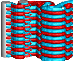
Figure 2. Flow past two tandem cylinders for  $\alpha =0$,
  $Lx=7.5D$ and
  $Re=220$: comparison between the effects of symmetry and periodic boundary conditions (BCs) employed on the lateral walls (
 $BCGF$ and
  $ADHE$ in figure 1) of the domain. In (e, f), red and cyan represent the iso-surfaces of streamwise vorticity
  $\omega _x=0.2$ and
  $-0.2$, respectively.
3.3. Validation and mesh resolution studies
The present stabilized finite element formulation was validated thoroughly in several of our previous studies (refer to Behara & Mittal Reference Behara and Mittal2010a,Reference Behara and Mittalb). To validate the method in this work, flow past an isolated cylinder is simulated in three dimensions at  $Re=300$. Table 1 shows the comparison of force coefficients and Strouhal frequency obtained in the present simulation with those reported in the literature. From this table, it can be observed that good agreement is achieved between the present and previous studies. In § 4, we will show that the flow parameters and the force coefficients predicted by the present simulation match the experimental results available in the literature. This aspect further validates the finite element formulation employed in this work.
Table 1. Average drag coefficient ( $\overline {C_D}$), r.m.s. value of lift coefficient (
 $C_{L,rms}$), and Strouhal frequency (
 $St$) obtained in present simulations and previous studies for an isolated cylinder at
  $Re=300$.

Table 2 presents the force coefficients obtained in the mesh resolution study. Two meshes, M1 and M2, are employed to simulate the flow past two tandem cylinders for  $\alpha =1$ and
  $Lx=2.5D$ at
  $Re=500$. Details of M1 and M2 are provided in the caption of table 2. In this table, one can see that the difference between the values predicted by the two meshes is less than
  $5\,\%$. Therefore, mesh M1 is employed for the simulations with
  $Lx=2.5D$. The same resolution is kept for the mesh utilized for
  $Lx=7.5D$. A time step
  $0.05$ is considered.
Table 2. Comparison of average and r.m.s. values of drag ( $\overline {C_D}$,
  $C_{D,rms}$) and lift (
 $\overline {C_L}$,
  $C_{L,rms}$) coefficients obtained by two meshes, M1 and M2, at
  $Re=500$, for
  $\alpha =1$ and
  $Lx=2.5D$. Numbers of nodes and elements of M1 are
  $1\,024\,335$ and
  $2\,002\,048$, and of M2 are
  $2\,032\,911$ and
  $4\,004\,096$.

4. Effect of the streamwise gap and rotation rate on flow parameters
4.1. Primary shedding frequency
It is observed that both the upstream and downstream cylinders shed the primary vortices at the same frequency. Figure 3 shows the variation of Strouhal number ( $St$) with
  $Re$ for non-rotating (
 $\alpha =0$) and rotating (
 $\alpha =1$) cases. In this figure, one can notice that
  $St$ for the streamwise gap
  $Lx=2.5D$ is significantly lower than that in the
  $Lx=7.5D$ case. This aspect is consistent with the observations of Deng et al. (Reference Deng, Ren, Zou and Shao2006), who showed that the primary shedding frequency for smaller gaps (
 ${\sim }3D$) is less than that of an isolated cylinder. The difference in
  $St$ for the two streamwise gaps is associated with different primary vortex shedding patterns, as can be seen in figure 4, which presents snapshots of the instantaneous flow field at
  $Re=220$. Figure 4(a) reveals that since the downstream cylinder (Cyl-B) interferes with the formation of Cyl-A's Kármán vortices for
  $Lx=2.5D$, those vortices are not shed in the interstitial space. Rather, they are amalgamated with the shear layers forming on the surface of Cyl-B (see figure 4a). This phenomenon results in the free shear layers, emanating from Cyl-B, becoming stronger and being extended to a certain far downstream location, where the eventual primary vortex shedding occurs, as shown in figure 4(a). This aspect leads to the primary shedding taking place at lower
  $St$ than the Strouhal frequency in the
  $Lx=7.5D$ case, wherein Cyl-A sheds the primary vortices in the gap space, as seen in figure 4(b).

Figure 3. Variation of Strouhal number ( $St$) with
  $Re$ for (a)
  $\alpha =0$ and (b)
  $\alpha =1$. Discontinuities in
  $St$, indicated by downward and upward arrows, are observed at the onset of Mode-A (
 $Re=200$) and Mode-B (
 $Re=250$) instabilities in the case
  $\alpha =0$ and
  $Lx=7.5D$, whereas no such discontinuities can be seen in any of the other cases.

Figure 4. Instantaneous spanwise vorticity ( $\omega _z$) field on the central 2-D plane at
  $Re=220$ and
  $\alpha =0$ for the streamwise gaps (a)
  $Lx=2.5D$ and (b)
  $Lx=7.5D$. Shear layers emanating from Cyl-A extend to a far downstream location in the wake of Cyl-B for
  $Lx=2.5D$, forming a longer vortex formation region compared to that in the
  $Lx=7.5D$ case, where primary vortex shedding occurs in the gap space.
From figure 3(a), it can be observed that the trend in the  $St$–
$St$– $Re$ plot corresponding to non-rotating (
 $\alpha =0$) cylinders with
  $Lx=7.5D$ is same as that observed by Behara & Mittal (Reference Behara and Mittal2010b) for an isolated cylinder. They showed that discontinuities occur in the
  $St$–
$St$– $Re$ relation, with the first one being associated with the beginning of Mode-A instability at
  $Re\sim 200$, and the second one with the appearance of Mode-B at
  $Re\sim 260$. Similar phenomena take place for Cyl-A in the
  $\alpha =0$ and
  $Lx=7.5D$ case, due to which the
  $St$ profile undergoes discontinuities at
  $Re=200$ (onset of Mode-A) and
  $Re=250$ (Mode-B begins); see figure 3(a). This trend is consistent with the observations of Williamson (Reference Williamson1996a), who demonstrated experimentally that the
  $St$ profile for a single cylinder exhibits discontinuities as Mode-A sets in at
  $Re\sim 189$, and Mode-B forms exclusively at
  ${Re\sim 240}$. On the other hand, at
  $\alpha =1$ and
  $Lx=7.5D$, the
  $St$ profile does not exhibit clear discontinuities (see figure 3b), unlike that for the non-rotating cylinders (figure 3a). In § 4, we will show that this difference in the
  $St$–
$St$– $Re$ relation for rotating cylinders is associated with different 3-D flow characteristics.
4.2. Fluid forces
The variation of mean drag coefficient  $\overline {C_D}$ with
  $Re$ is shown in figure 5. In this figure,
  $\overline {C_D}$ values predicted by the present numerical simulations for
  $Lx=2.5D$ and
  $7.5D$ are compared with the experimental results for an isolated non-rotating cylinder (Schlichting & Gersten Reference Schlichting and Gersten2017). From figure 5(a), one can notice that in the
  $\alpha =0$ and
  $Lx=7.5D$ case, Cyl-A experiences less drag compared to the isolated cylinder for
  $Re\le 250$, whereas
  $\overline {C_D}$ matches that of the isolated body for
  $Re\ge 280$. This aspect clearly indicates that the stagnation pressure field of the downstream body (Cyl-B) in the
  $Lx=7.5D$ case significantly influences the flow in the near wake of Cyl-A up to
  $Re=250$ so as to reduce the pressure difference between upstream and downstream sides of the body. This phenomenon leads to reduced drag on Cyl-A for
  $Re\le 250$, whereas the influence of the stagnation pressure of Cyl-B on the near-wake region of Cyl-A diminishes for
  $Re\ge 280$, due to which
  $\overline {C_D}$ of Cyl-A appears closer to that of the isolated body (see figure 5a).

Figure 5. Variation of mean drag coefficient ( $\overline {C_D}$) with
  $Re$ for (a) non-rotating (
 $\alpha =0$) and (b) rotating (
 $\alpha =1$) cylinders. Downward arrows indicate the jump at
  ${Re=255}$ for
  $\alpha =1$ and
  $Lx=2.5D$.
In figure 5(a), it is noticeable that close proximity of Cyl-B in the  $Lx=2.5D$ case causes less drag on Cyl-A than its counterpart at
  $Lx=7.5D$, and negative
  $\overline {C_D}$ on Cyl-B. For this gap (
 $Lx=2.5D$), which is too small for Cyl-A to shed the primary vortices, the free shear layers emanating from Cyl-A extend to a far downstream location in Cyl-B's wake, before Kármán vortices are shed (see figure 4a). This situation results in the appearance of recirculation (suction) regions in both upstream and downstream sides of Cyl-B, as can be seen in figure 6, which shows the mean pressure field and streamlines for
  $\alpha =0$ and
  $Lx=2.5D$. Figure 7 presents the mean pressure coefficients (
 $\overline {C_P}$) on Cyl-B. In figure 7, one can see that the suction at the upstream side (at
  $\theta =0^\circ$ and
  $360^\circ$) of Cyl-B in the
  $Lx=2.5D$ case is stronger than that in the downstream side (at
  $\theta =180^\circ$). Therefore, Cyl-B experiences negative drag for
  $Lx=2.5D$ as seen in figure 5(a). We refer to the drag acting opposite to the freestream direction as negative drag, while the drag acting in the freestream direction is referred to as positive drag. From figure 5(a), it can be observed further that as the streamwise gap increases to
  $7.5D$, positive
  $\overline {C_D}$ acts on Cyl-B. This trend is consistent with the observations of Meneghini, Saltara & Siqueira (Reference Meneghini, Saltara, Siqueira and Ferrari2001) and Carmo & Meneghini (Reference Carmo and Meneghini2006), who showed that the drag of the downstream cylinder changes from negative to positive values for
  $Lx\ge 3.5D$. For such larger gaps, the upstream cylinder sheds primary vortices, which move downstream in the gap region and impinge on the downstream body. Consequently, the stagnation pressure at
  $\theta =0^\circ$ and
  $360^\circ$ on Cyl-B becomes higher than the pressure at its base (at
  $\theta =180^\circ$), as can be seen in figure 7. This phenomenon causes positive drag acting on the downstream body (refer to figure 5a).

Figure 6. Time- and span-averaged pressure field and streamlines at  $Re=220$,
  $Lx=2.5D$ and
  $\alpha =0$. Recirculation zones form in the gap space and the near wake of the downstream cylinder.

Figure 7. Distribution of time- and span-averaged coefficient of pressure ( $\overline {C_{P}}$) on Cyl-B at
  $Re=220$ and
  $\alpha =0$. Schematic shows the meaning of
  $\theta$, where
  $\theta =0^\circ$ and
  $360^\circ$ at the upstream end, and
  $\theta =180^\circ$ at the downstream end (cylinder's base). Coefficient
  $\overline {C_{P}}$ is lower at the upstream end than that at the base, resulting in negative drag on Cyl-B for
  $Lx=2.5D$.
When the cylinders rotate at  $\alpha =1$,
  $\overline {C_D}$ exhibits a downward jump at
  ${Re=255}$ in the
  $Lx=2.5D$ case, as seen in figure 5(b), whereas this jump is not observed for
  $Lx=7.5D$. Figure 8 shows the variation of r.m.s. values of drag (
 $C_{D,rms}$) and lift (
 $C_{L,rms}$) coefficients with
  $Re$. From this figure, it can be observed that the r.m.s. values also undergo a downward jump at
  ${Re=255}$. This aspect indicates that the wake fluctuations get moderated as
  $Re$ is increased to
  $255$. This phenomenon is more obvious in figure 9, which shows the time histories of streamwise (
 $u$) and cross-flow (
 $v$) velocity components measured in the interstitial space at
  $Re=250$ and
  $255$. From this figure, it can be observed that the amplitudes of velocity signals decrease considerably at
  ${Re=255}$. Therefore, peak to peak variations of the force coefficients jump down to lower values at
  ${Re=255}$, as seen in figure 10, which presents
  $C_L$–
 $C_D$ phase plots.

Figure 8. Variation of (a)  ${C_{D,rms}}$ and (b)
  ${C_{L,rms}}$ with
  $Re$ for rotating cylinders (
 $\alpha =1$). Downward arrows indicate the jump in force coefficients at
  ${Re=255}$ for
  $Lx=2.5D$.

Figure 9. Time histories of streamwise velocity ( $u$) and cross-flow velocity (
 $v$) at
  $Re=250$ and
  $255$ for
  $\alpha =1$ and
  $Lx=2.5D$. Velocity components are measured at
  $x/D=1.7797$,
  $y/D=0.0913$ and
  $z/D=4.125$. Unsteadiness in the flow parameters decreases as Mode-B instability in the wake begins at
  $Re=255$.

Figure 10. Variation of lift coefficient ( $C_{L}$) with drag coefficient (
 $C_{D}$) for (a) Cyl-A and (b) Cyl-B, at
  $Re=250$ and
  $255$, for
  $\alpha =1$ and
  $Lx=2.5D$. Peak to peak variations of force coefficients become significantly lower at
  $Re=255$ as the wake shifts from being associated with Mode-A to Mode-B instability.
In figure 9, we have seen that for  $Re\ge 255$ (i.e. beyond the discontinuity), flow is characterized by moderated wake fluctuations. From this figure, it can be observed further that the velocity signals corresponding to
  $Re=250$ and
  $255$ exhibit the same number of cycles for the considered time, indicating that the primary shedding frequency does not change even as the near-wake fluctuations decrease and a discontinuity occurs in the profiles of force coefficients. To further understand the flow mechanism that causes the downward jump, we will study the mean flow field at Reynolds numbers across the discontinuity in § 4.3.
In figure 8, it is seen that as the fluid forces jump downwards at  $Re=255$ in the
  $\alpha =1$ and
  $Lx=2.5D$ case, they follow the lower path for
  $Re\ge 255$. This aspect raises the obvious question: does the discontinuity in fluid forces occur for other values of rotation rate (
 $\alpha$)? To address this question, we studied the wake transition for
  $\alpha =0.5$ and
  $2$. Figure 11 shows the variation of
  $C_{D,rms}$ with
  $Re$ for
  $\alpha =0.5$ and
  $Lx=2.5D$, and the time histories of
  $C_D$ acting on Cyl-A and the spanwise component of velocity (
 $w$), measured in the gap space, for
  $Re=180$ and
  $220$. From figure 11(a), it can be observed that
  $C_{D,rms}$ corresponding to the
  $\alpha =0.5$ case follows the lower path for all the
  $Re$ values considered. This trend is similar to the variation of force coefficients for
  $Re\ge 255$, i.e. after the discontinuity occurs for
  $\alpha =1$, as seen in figure 11(a). The time histories for
  $\alpha =0.5$ in figure 11(b) reveal that at
  $Re=180$, even though the fully evolved flow is 2-D with
  $w\sim 0$, an intermediate instability that occurs between
  $t\sim 400$ and
  $t\sim 600$ leads to decrease in the peak to peak amplitude of
  $C_D$. A similar phenomenon occurs in the
  $Re=220$ flow as well, as shown in figure 11(c). However, the corresponding time history of
  $w$ indicates that the 3-D wake transition eventually begins at
  $Re=220$. From this aspect, it can be inferred clearly that contrary to the
  $\alpha =1$ case, the force coefficients and the associated near-wake fluctuations are moderated at all
  $Re$ considered for
  $\alpha =0.5$, irrespective of the 3-D wake transition. Differences in the characteristics of 3-D instabilities associated with
  $\alpha =0.5$ and
  $1$ will be discussed in detail in § 5.3. Unlike for
  $\alpha =0.5$, as the rotation rate is increased to
  $\alpha =2$, discontinuities in fluid forces are observed. This aspect will be elaborated in § 5.5.

Figure 11. Flow past tandem cylinders for  $\alpha =0.5$ and
  $Lx = 2.5D$: (a) variation of
  $C_{D,rms}$ with
  $Re$, time histories of
  $C_D$ acting on Cyl-A, and the spanwise component of velocity (
 $w$) measured in the gap space for (b)
  $Re = 180$ and (c)
  $Re = 220$. Here,
  $C_{D,rms}$ of the
  $\alpha =1$ and
  $Lx = 2.5D$ case is shown for reference. Simulation at each
  $Re$ is performed, providing the uniform flow throughout the domain as initial condition. For
  $\alpha =0.5$, force coefficients take the lower path at all the
  $Re$ values considered.
4.3. Mean flow field across the discontinuity at  $\alpha =1$

Figure 12 presents the time- and span-averaged pressure field and streamlines at  $Re=250$ and
  $255$ for
  $Lx=2.5D$ and
  $\alpha =1$, while the distributions of mean pressure coefficient (
 $\overline {C_P}$) on both the cylinders are shown in figure 13. Recall that the downward jump in force coefficients takes place at
  $Re=255$ (see figures 5 and 8).

Figure 12. Time- and span-averaged pressure and streamlines at (a)  $Re=250$ and (b)
  $Re=255$ for
  $\alpha =1$ and
  $Lx=2.5D$. Here, A1 and B1–B4 indicate the recirculation zones. A pair of opposite-signed recirculation zones mitigate the effect of each other, leading to a decrease in net pressure force acting on the cylinders at
  $Re=255$.

Figure 13. Variation of time- and span-averaged pressure coefficient ( $\overline {C_{P}}$) along the circumference of (a) Cyl-A and (b) Cyl-B for
  $\alpha =1$ and
  $Lx=2.5D$. The schematic in (a) shows the meaning of
  $\theta$, where
  $\theta =0^\circ$ and
  $360^\circ$ at the upstream end, and
  $\theta =180^\circ$ at the downstream end (cylinder's base). Areas marked with green and brown dashed lines show the difference in
  $\overline {C_{P}}$ between the
  $Re=250$ and
  $255$ cases on the upper shoulder and base of the body, respectively.
In figure 12(a), one can notice that at  $Re=250$, a recirculation zone (A1) forms in the near wake of Cyl-A, while no recirculation zone appears in Cyl-B's vicinity. However, the wake in the
  $Re=255$ flow is characterized by the appearance of two pairs of opposite recirculation zones, with one pair (B1 and B2) being in the wake of Cyl-A, and the other (B3 and B4) in the vicinity of Cyl-B, as shown in figure 12(b). The single recirculation zone induces higher suction (lower pressure) in Cyl-A's near wake for
  $Re=250$ than that observed in the wake of upstream cylinder at
  $Re=255$. This aspect can be seen clearly in the
  $\overline {C_{P}}$ profiles in figure 13. The areas marked with green and brown dashed lines in this figure point out the difference in suction that forms on the upper shoulder (
 $\theta =90^\circ$) and at the base (
 $\theta =180^\circ$) of the cylinders for
  $Re=250$ and
  $255$. One can notice that suction on both the cylinders at
  $Re=250$ is higher (i.e.
  $\overline {C_{P}}$ is lower) than that in the
  $Re=255$ case. This aspect indicates that the net pressure force acting on the cylinders is higher for
  $Re=250$ as this force decreases at
  $Re=255$, due to which fluid forces undergo a downward jump (see figures 5 and 8). While a single recirculation zone induces more intense suction in Cyl-A's near wake at
  $Re=250$, the two opposite-signed recirculation zones observed for
  $Re=255$ mitigate each other's effects, leading to recovery of pressure to a certain extent in the near wakes of both bodies. This phenomenon causes a reduction in the intensity of suction forming on the upper shoulder and base of the cylinders in the
  $Re=255$ flow, compared to the corresponding suction regions at
  $Re=250$, as shown in the green and brown areas in figure 13. Therefore, the net pressure force acting on the cylinders decreases significantly, causing the discontinuity in force coefficients at
  ${Re=255}$, as seen in figures 5 and 8.
5. Vortex shedding during wake transition
In this section, we will study the effect of streamwise gap ( $Lx$) and the rotation rate (for
  $\alpha =0$ and
  $1$) on the primary and secondary vortex shedding of both the cylinders, as the wake undergoes 3-D transition. Figures 14, 16, 17, 19 and 21 show the iso-surfaces of streamwise (
 $\omega _x$) and spanwise (
 $\omega _z$) vorticity at various
  $Re$ for various combinations of
  $\alpha$ and
  $Lx$.
$Lx$.

Figure 14. Wake transition for  $\alpha =0$ and
  $Lx=2.5D$: iso-surfaces of streamwise (
 $\omega _x$) and spanwise (
 $\omega _z$) vorticity at different
  $Re$. Red and cyan represent positive and negative vorticity, respectively. Onset of 3-D transition is delayed to
  $Re\sim 280$ due to the proximity of Cyl-B with Cyl-A. Here: (a)
  ${Re}= 280$,
  $\omega _x=\pm 0.01$; (b)
  ${Re}= 280$,
  $\omega _z=\pm 0.2$; (c)
  ${Re}= 350$,
  $\omega _x=\pm 0.1$; (d)
  ${Re}= 350$,
  $\omega _z=\pm 0.2$.
5.1. Flow at $\alpha =0$ and $Lx=2.5D$


The present simulations predicted that for the tandem cylinders in the  $\alpha =0$ and
  $Lx=2.5D$ case, the onset of 3-D wake transition is delayed to higher
  $Re$, compared to that of an isolated cylinder. Carmo et al. (Reference Carmo, Meneghini and Sherwin2010) found that in the case of closely placed tandem cylinders, the downstream body suppresses Mode-A flow instability up to higher
  $Re$, as the primary vortex shedding takes place at a certain far downstream location of the downstream cylinder. It is well known that Mode-A originates as an elliptic instability in the cores of primary vortices (Leweke & Williamson Reference Leweke and Williamson1998; Thompson et al. Reference Thompson, Leweke and Williamson2001). Therefore, primary vortex shedding activity occurring at a far downstream location leads to the delayed onset of 3-D transition (Carmo et al. Reference Carmo, Meneghini and Sherwin2010). Consistent with the above-mentioned observations, we noticed that the 3-D transition in the wake of non-rotating cylinders with
  $Lx=2.5D$ begins at
  $Re\sim 280$, as the primary vortex shedding takes place at a far downstream location (refer to figure 4a). In figure 14(a), one can notice that at
  $Re=280$, weaker streamwise flow structures (
 $\omega _x=\pm 0.01$) form throughout the wake region. Furthermore, from figures 14(a) and 14(c), it can be observed that the 3-D instability appears in the interstitial space as well. Figure 15 shows the spanwise distribution of streamwise vorticity (
 $\omega _x$), measured in the near-wake regions of the two cylinders for
  $Re=280$. From figure 15(a), it can be observed that the 3-D instability in the gap space forms at spanwise wavelength
  $\lambda \sim 5D$. Although primary vortex shedding from Cyl-A does not occur in the gap,
  $Lx=2.5D$ is sufficient for the recirculation bubbles to form in the near-wake region of the upstream cylinder, as seen in figure 6. We surmise that the 3-D instability (see figures 14a,c) begins in the cores of the recirculation bubbles in the gap space. This aspect needs further investigation.

Figure 15. Variation of instantaneous spanwise vorticity ( $\omega _x$) along the domain's span in the near wake of (a) Cyl-A at
  $x/D=1.821$,
  $y/D=0.147$, and (b) Cyl-B at
  $x/D=4.916$,
  $y/D=0.537$, for
  $Re=280$,
  $\alpha =0$ and
  $Lx=2.5D$. Here, 3-D flow structures appear with larger spanwise wavelength (
 $\lambda \sim 5D$) at the origin in the gap space, but break into smaller-scale vortices having
  $\lambda \sim 2D$ in Cyl-B’s wake.
The wavelength of the streamwise flow structures at  $Re=280$ decreases as they convect downstream. Figure 15(b) shows that in the near wake of Cyl-B,
  $\lambda \sim 2D$, while the streamwise flow structures appear regularly spaced along the span, as seen in figure 14(a). Since
  $\omega _x$ is rather weak at
  $Re=280$, Kármán vortices appear coherent all along the domain (see figure 14b). With increase in
  $Re$, the 3-D instability becomes stronger and loses its regular pattern. From figures 14(c) and 14(d), one can notice that at
  $Re=350$, the streamwise flow structure resembles Mode-A instability with
  $\lambda \sim 4D$ and the Kármán vortices undergoing spanwise undulation. This phenomenon is analogous to the association of Mode-A instability with dislocations in the primary vortices of an isolated cylinder (Williamson Reference Williamson1996a; Behara & Mittal Reference Behara and Mittal2010b). We examined the 3-D flow structures at higher
  $Re$ (up to
  $Re=500$) for
  $Lx=2.5D$ and
  $\alpha =0$. Mode-B like instability is not found in the flow. Rather, these Mode-A flow structures become stronger as
  $Re$ increases, leading to more dislocations in the primary vortices. Therefore, one can infer that the 3-D wake transition in the case of tandem non-rotating cylinders with
  $Lx=2.5D$ takes place via Mode-A instability.
5.2. Flow at $\alpha =0$ and $Lx=7.5D$


For the gap  $Lx=7.5D$, as the upstream cylinder sheds the primary vortices, its wake characteristics and fluid forces appear almost the same as those of an isolated body. A discontinuity occurs in the
  $St$–
$St$– $Re$ profile as Mode-A instability begins in the near wake of Cyl-A at
  $Re=200$ (refer to figure 3a). This
  $Re$ is the same as the critical
  $Re$ of an isolated cylinder reported by Behara & Mittal (Reference Behara and Mittal2010b). However, contrary to this aspect, Carmo et al. (Reference Carmo, Meneghini and Sherwin2010) noticed that the transition starts at a lower
  $Re$ for
  $Lx=5D$, as the stagnation pressure on the downstream cylinder affects the near wake of the upstream body. We surmise that since the gap (
 $Lx=7.5D$) in the present case is larger than that (
 $Lx=5D$) studied by Carmo et al. (Reference Carmo, Meneghini and Sherwin2010), the stagnation pressure corresponding to Cyl-B does not have influence on the Cyl-A near wake to the extent of inducing the early onset of 3-D transition.
In figure 16, one can see that the wake transitions via Mode-A and Mode-B instabilities for Cyl-A like the case of isolated cylinder. Figure 16(a) shows that at  $Re=220$, strong streamwise flow structures (
 $\omega _x=\pm 0.2$) form in the near of wake of Cyl-A. Also, the primary vortices shed by the upstream body in the interstitial space undergo considerable spanwise undulation. These aspects confirm that the wake of Cyl-A is characterized with Mode-A instability at
  $Re=220$. The mode-A flow structures extend throughout the domain, as dislocations form in the primary vortices shed by Cyl-B, as shown in figures 16(a) and 16(b).

Figure 16. Wake transition for  $\alpha =0$ and
  $Lx=7.5D$: iso-surfaces of streamwise (
 $\omega _x$) and spanwise (
 $\omega _z$) vorticity at different
  $Re$. For the meaning of red and cyan, see the caption of figure 14. The 3-D wake transition occurs via Mode-A and Mode-B instabilities for Cyl-A, whereas Cyl-B's wake transitions through Mode-A only. Here: (a)
  ${Re}= 220$,
  $\omega _x=\pm 0.2$; (b)
  ${Re}= 220$,
  $\omega _z=\pm 0.2$; (c)
  ${Re}= 300$,
  $\omega _x=\pm 0.2$; (d)
  ${Re}= 300$,
  $\omega _z=\pm 0.2$.
From figure 16(c), it can be observed that the near wake of the upstream cylinder is associated with Mode-B flow structures, whose spanwise wavelength ( ${\sim}1D$) is much smaller than that at
  $Re=220$. In this case, the primary vortices shed by Cyl-A in the interstitial space appear coherent as seen in figure 16(d), suggesting that the 3-D instability occurs in the braid region of primary vortices. These aspects are in line with the observations of Williamson (Reference Williamson1996a) and Behara & Mittal (Reference Behara and Mittal2010b) with regard to Mode-B instability. However, figure 16(c) reveals that while Mode-B flow structures form in Cyl-A's vicinity at
  $Re=300$, Mode-A instability occurs in the wake of the downstream cylinder. This aspect can be further confirmed by the appearance of dislocations in the primary vortices shed by Cyl-B as seen in figure 16(d). These phenomena clearly indicate that 3-D transition in the wake of downstream cylinder takes place via only Mode-A instability for
  $Lx=7.5D$. Recall that the wake of non-rotating Cyl-B in the
  $Lx=2.5D$ case transitions to a 3-D state through Mode-A only (refer to § 5.1). This aspect indicates that for
  $\alpha =0$, the wake of the downstream cylinder undergoes 3-D transition via only Mode-A, irrespective of the gap between the two bodies.
5.3. Flow at $\alpha =0.5,1$ and $Lx=2.5D$


As cylinders in the  $Lx=2.5D$ case rotate with
  $\alpha =1$, a discontinuity occurs in the profiles of fluid forces as they experience a sudden downward jump at
  $Re=255$ (refer to § 4.2). When the bodies rotate at
  $\alpha =0.5$, fluid forces for all
  $Re$ follow the lower path on the force coefficients versus
  $Re$ plot (figure 11), as observed for
  $\alpha =1$ beyond the discontinuity. In this subsection, we will study how the 3-D instability changes across the discontinuity.
For the streamwise gap  $Lx=2.5D$, 3-D wake transition begins at a lower
  $Re$ when cylinders rotate, compared to the case with non-rotating cylinders. Recall that the wake transition in the
  $\alpha =0$ and
  $Lx=2.5D$ case is delayed to
  $Re\sim 280$ (refer to § 5.1). However, for rotating cylinders, 3-D instability sets in at
  $Re\sim 220$, as shown in figure 17. At this
  $Re$, the streamwise flow structures form along the span in a well-ordered pattern, while the Kármán vortices maintain spanwise coherence (figures 17a,b). With increase in
  $Re$, patterns of the 3-D instability and the primary shedding remain largely invariable for
  $Re\le 250$, as shown in figures 17(a) to 17(d). However, spanwise waviness in the shear layers can be seen more clearly at
  $Re=250$ (figure 17d). This aspect indicates that the 3-D instability originates in the braid region. Figure 18 shows the spanwise waveform of streamwise vorticity (
 $\omega _x$) measured in the near wake. In figure 18(a), one can notice that at
  $Re=250$,
  $\omega _x$ is distributed regularly with approximately 6 periodic cycles appearing over the domain's span of
  $8D$, resulting in the spanwise wavelength
  $\lambda \sim 1.3D$. This wavelength and the regular pattern of streamwise flow structures in the wake suggest that the 3-D instability resembles Mode-C observed by Rao et al. (Reference Rao, Leontini, Thompson and Hourigan2013) for an isolated rotating cylinder. Their studies revealed that wake transition begins with the appearance of Mode-C at
  $Re\sim 230$, as the flow on one side of the rotating cylinder is accelerated, creating the spatio-temporal asymmetric wake for
  $\alpha \sim 1.5\unicode{x2013}1.85$. This range of rotation rate is higher than the present value of
  $\alpha$ (
 $=0.5$) at which Mode-C occurs. The reason can be attributed to the two co-rotating in-line cylinders, being closely placed (
 $Lx=2.5D$), enhancing the asymmetry in the near wake as the (red) shear layer on the lower side becomes significantly weaker than its counterpart on the upper surface. As a result, wake transition begins with Mode-C appearing for
  $Re\sim 220\unicode{x2013}250$ in the
  $\alpha =0.5$ and
  $Lx=2.5D$ case (figure 17).

Figure 17. Wake transition for  $\alpha =0.5$ and
  $Lx=2.5D$: iso-surfaces of streamwise (
 $\omega _x$) and spanwise (
 $\omega _z$) vorticity at different
  $Re$. For the meaning of red and cyan, see the caption of figure 14. Wake transition takes place via Mode-C (for
  $Re\le 250$) and Mode-D (for
  $Re>250$) instabilities. Here: (a)
  ${Re}= 220$,
  $\omega _x=\pm 0.01$; (b)
  ${Re}= 220$,
  $\omega _z=\pm 0.2$; (c)
  ${Re}= 250$,
  $\omega _x=\pm 0.01$; (d)
  ${Re}= 250$,
  $\omega _z=\pm 0.2$; (e)
  ${Re}= 300$,
  $\omega _x=\pm 0.05$; ( f)
  ${Re}= 300$,
  $\omega _z=\pm 0.2$.

Figure 18. Variation of instantaneous spanwise vorticity ( $\omega _x$) along the domain's span at (a)
  $Re=250$ and (b)
  $Re=300$, for
  $\alpha =0.5$ and
  $Lx=2.5D$. Here,
  $\omega _x$ is measured at
  $x/D=1.397$ and
  $y/D=0.413$. The wavelengths of 3-D instability
  $\lambda \sim 1.3D$ at
  $Re=250$ and
  $\lambda \sim 2.3D$ at
  $Re=300$ suggest that the wake transitions via Mode-C and Mode-D instabilities.
As  $Re$ increases further, the 3-D instability becomes stronger, while streamwise flow structures form at a higher spanwise wavelength, as seen at
  $Re=300$ in figure 17(e). In this case, nearly 3.5 cycles of
  $\omega _x$ appear along the span at
  $\lambda \sim 2.3D$ (figure 18b). This flow structure appears like Mode-D instability, which is observed by Rao et al. (Reference Rao, Leontini, Thompson and Hourigan2013) for an isolated rotating cylinder. Rao et al. (Reference Rao, Leontini, Thompson and Hourigan2013) showed Mode-D structures forming in a regular pattern along the span with
  $\lambda \sim 2D$. They proposed that Mode-D grows as the flow accelerates, moving downstream of the hyperbolic stagnation point that forms at the rear end of recirculation zone in the near wake. Consistent with this proposed mechanism, in the present case, considerable spanwise waviness occurs at the end of the free shear layers (figure 17 f), as Mode-D flow structures evolve moving downstream (figure 17e). However, Rao et al. (Reference Rao, Leontini, Thompson and Hourigan2013) noticed Mode-D instability in the wake of an isolated rotating cylinder for
  $Re=300$ and
  $\alpha =1.9$, whereas in the present case, Mode-D occurs at a lower rotation rate (
 $\alpha =0.5$) since the effect of rotation on the flow increases as it passes from Cyl-A to the closely placed (
 $Lx=2.5D$) Cyl-B.
Williamson (Reference Williamson1996a) observed that Mode-B instability occurs in the braid region, leading to the appearance of rib structures between the Kármán vortices, which maintain spanwise coherence, unlike the case of Mode-A that causes undulation in the primary vortex cores. In the present case, a similar phenomenon occurs for Mode-D instability as well. From figure 17( f), it can be observed that the negative (cyan) vortices are well coherent all along the span as the flow is associated with Mode-D instability, clearly indicating that like Mode-B, Mode-D also originates in the braid region between the primary vortices. However, the rotation of cylinders further weakens the (red) shear layer on the lower side as  $Re$ increases, due to which the corresponding (red) primary vortices lose spanwise coherence at
  $Re=300$, as they convect downstream (figure 17 f).
As the cylinders rotate at  $\alpha =1$, the onset of the 3-D transition occurs almost at the same
  $Re$ (
 $\sim$220) as that observed for
  $\alpha =0.5$. In figure 19, it can be seen that at the beginning of transition (for
  $Re=220$), the wake is characterized by the undulations in shear layers, which causes the formation of nearly periodic streamwise flow structures having
  $\lambda \sim 2.3D$ in the near wake. Figure 20 shows the spanwise distribution of
  $\omega _x$ for different
  $Re$. From figure 20(a), it can be observed that 3.5 cycles of
  $\omega _x$ appear along the span, confirming that
  $\lambda \sim 2.3D$. These aspects point to Mode-D instability, which is observed for
  $Re=300$ and
  $\alpha =0.5$ as well (refer to figure 17). As
  $Re$ is increased further, streamwise flow structures lose their orderly pattern as shown in figure 19(c). This aspect is clearly evident in figure 20(b), which shows a non-periodic spanwise wave of
  $\omega _x$ at
  $Re=250$. As the (red) shear layer on the lower side of the rotating cylinders becomes weaker for increasing
  $Re$, dislocations appear in the corresponding (red) primary vortex structures (figures 19b,d), whereas the (cyan) vortices shed from the upper side of the bodies maintain their spanwise coherence up to far downstream locations. This aspect further confirms that Mode-D instability occurs in the braid regions.

Figure 19. Wake transition for  $\alpha =1$ and
  $Lx=2.5D$: iso-surfaces of streamwise (
 $\omega _x$) and spanwise (
 $\omega _z$) vorticity at different
  $Re$. For the meaning of red and cyan, see the caption of figure 14. The wake is characterized by Mode-D for
  $Re\le 250$, while Mode-D
 $^\prime$ begins at
  $R=255$. Here: (a)
  ${Re}= 220$,
  $\omega _x=\pm 0.05$; (b)
  ${Re}= 220$,
  $\omega _z=\pm 0.2$; (c)
  ${Re}= 250$,
  $\omega _x=\pm 0.05$; (d)
  ${Re}= 250$,
  $\omega _z=\pm 0.2$; (e)
  ${Re}= 255$,
  $\omega _x=\pm 0.05$; ( f)
  ${Re}= 255$,
  $\omega _z=\pm 0.2$.

Figure 20. Variation of instantaneous spanwise vorticity ( $\omega _x$) along the domain's span at (a)
  $Re=220$, (b)
  $Re=250$ and (c)
  $Re=255$, for
  $\alpha =1$ and
  $Lx=2.5D$. Here,
  $\omega _x$ is measured at
  $x/D=1.397$ and
  $y/D=0.413$. The wavelength of the 3-D instability and the strength of vorticity decrease as
  $Re$ is increased to
  $255$, where a downward jump occurs in the fluid force versus
  $Re$ plots.
When  $Re$ is increased to
  $255$, a certain change in the secondary vortex structures occurs, as seen in figure 19(e). In this figure, it is noticeable that the spanwise wavelength decreases as more secondary vortices appear along the span. The corresponding waveform of
  $\omega _x$ in figure 20(c) shows that the spanwise wavelength of streamwise vortices is approximately
  $1.3D$. Free shear layers in the near wake exhibit spanwise undulations (figure 19 f) as the streamwise flow structures are amplified moving downstream. The associated negative (cyan) primary vortices are seen to maintain spanwise coherence up to a far downstream location, while the positive (red) vortices, being weaker, undergo distortions in the near wake and eventually break in the far wake, as shown in figure 19( f). These wake characteristics appear similar to those seen in the
  $Re=220$ case (figure 19b), except for the lower wavelength (
 $\lambda \sim 1.3$ at
  $Re=255$, while
  $\lambda \sim 2.3$ at
  $Re=220$). Therefore, we refer to this 3-D instability as Mode-D
 $^\prime$. As the onset of Mode-D
 $^\prime$ instability occurs at
  $Re=255$, a pair of opposite-signed recirculation zones forms in the near vicinity for both the cylinders, as seen in figure 12. These recirculation zones mitigate the effects of each other, resulting in significantly reduced near-wake fluctuations, thus leading to a discontinuity in the profiles of force coefficients (refer to § 4.2).
5.4. Flow at $\alpha =1$ and $Lx=7.5D$


With the increase in the streamwise gap between the two cylinders, the near wake of the upstream body exhibits the same characteristics as those of an isolated cylinder's wake. In the past, a few studies, such as Akoury et al. (Reference Akoury, Braza, Perrin, Harran and Hoarau2008) and Rao et al. (Reference Rao, Leontini, Thompson and Hourigan2013, Reference Rao, Radi, Leontini, Thompson, Sheridan and Hourigan2015), showed that the critical  $Re$ at which 3-D transition occurs is delayed to a higher value for an isolated cylinder rotating with
  $\alpha \ge 1$. The present simulations predicted that the 3-D transition in the wake of Cyl-A for
  $\alpha =1$ and
  $Lx=7.5D$ begins at a Reynolds number as high as
  $320$. Figure 21(a) shows clearly that at
  $Re=310$, 3-D instability does not appear in the near wake of Cyl-A, while Mode-A flow structures form in the downstream of Cyl-B. The primary vortices shed by the upstream cylinder are coherent all along the span, with no trace of 3-D instability being found in the interstitial space, as seen in figure 21(b). At the same time, Cyl-B's wake is characterized by dislocations in primary vortices, since the downstream body interacts with the wake of Cyl-A that triggers the 3-D transition.

Figure 21. Wake transition for  $\alpha =1$ and
  $Lx=7.5D$: iso-surfaces of streamwise (
 $\omega _x$) and spanwise (
 $\omega _z$) vorticity at different
  $Re$. For the meaning of red and cyan, see the caption of figure 14. The wake transition is delayed to
  $Re=310$ for Cyl-B and
  $Re=320$ for Cyl-A. Here: (a)
  ${Re}= 310$,
  $\omega _x=\pm 0.1$; (b)
  ${Re}= 310$,
  $\omega _z=\pm 0.2$; (c)
  ${Re}= 320$,
  $\omega _x=\pm 0.1$; (d)
  ${Re}= 320$,
  $\omega _z=\pm 0.2$; (e)
  ${Re}= 420$,
  $\omega _x=\pm 0.2$; (f)
  ${Re}= 420$,
  $\omega _z=\pm 0.2$.
As the Reynolds number is increased to  $Re\ge 320$, Mode-B instability appears in Cyl-A's wake. From figures 21(c) and 21(d), it can be observed that tiny streamwise flow structures form in the gap region, and the Kármán vortices shed by Cyl-A appear to be well coherent along the span. On the other hand, Cyl-B's wake is always characterized by 3-D flow structures of higher spanwise wavelength, compared to those in the wake of Cyl-A, and also dislocations form in the primary vortices shed by Cyl-B. This aspect is similar to the
  $\alpha =0$ case, where 3-D transition in Cyl-B's wake occurs via Mode-A instability only irrespective of the streamwise gap due to interaction of the downstream body with the upstream cylinder's wake (refer to §§ 5.1 and 5.2). Figure 22 shows the distribution of
  $\omega _x$ along domain's span, measured at downstream locations of both the cylinders for
  $Re=320$. In this figure, it can be noticed that
  $\omega _x$ exhibits the spanwise wavelengths
  $\lambda \sim 1D$ and
  $4D$ for Cyl-A and Cyl-B, respectively. These flow patterns persist even as
  $Re$ increases further, as can be seen in figures 21(e) and 21( f). From these observations, one can infer that staggered transition occurs in the
  $\alpha =1$ and
  $Lx=7.5D$ case, where Cyl-A's wake transitions via Mode-B instability, while for Cyl-B it is only Mode-A instability that takes the wake through 3-D transition.

Figure 22. Variation of instantaneous spanwise vorticity ( $\omega _x$) along the domain's span in the near wake of (a) Cyl-A and (b) Cyl-B, for
  $Re=320$,
  $\alpha =1$ and
  $Lx=7.5D$. Wavelengths
  $\lambda \sim 1D$ (for Cyl-A) and
  $4D$ (Cyl-B) indicate that Mode-B and Mode-A instabilities occur respectively in the wakes of Cyl-A and Cyl-B.
As the flow is characterized by 2-D vortex shedding for  $Re<310$, thereafter undergoing staggered transition for both the cylinders at
  $\alpha =1$ and
  $Lx=7.5D$, the corresponding
  $St$ profile does not exhibit the discontinuities (refer to figure 3b) that are found at the onset of Mode-A and Mode-B instabilities for non-rotating cylinders. Recall that for
  $\alpha =0$ and
  $Lx=7.5D$, Cyl-A's wake transitions to 3-D state via Mode-A and Mode-B instabilities like the case of an isolated cylinder, and this phenomenon leads to discontinuities in the
  $St$–
$St$– $Re$ relation as seen in figure 3(a). However, figure 3(b) shows that such discontinuities do not occur in
  $St$ for
  $\alpha =1$, as the transition occurs for
  $Re\ge 310$ with only Mode-B and only Mode-A instabilities appearing in the near-wake regions of upstream and downstream cylinders, respectively.
5.5. Flow at $\alpha =2$ and $Lx=2.5D$


In § 5.3, it is seen that for  $\alpha =0.5$ and
  $Lx=2.5D$, wake transition occurs via Mode-C and Mode-D instabilities, whereas when the rotation rate is increased to
  $\alpha =1$, Mode-D (for
  $Re\le 250$) and Mode-D
 $^\prime$ (for
  $Re\ge 255$) appear in the flow. Furthermore, the shift in the mode of 3-D instability is associated with a downward jump in the variation of force coefficients with
  $Re$ for
  $\alpha =1$, while at
  $\alpha =0.5$, r.m.s. values of force coefficients follow the lower path with respect to
  $Re$ (see figure 11). It will be interesting to see if such a discontinuity happens when the rotation rate is increased further. Figure 23 shows
  $C_{D,rms}$ and
  $C_{L,rms}$ as functions of
  $Re$, while figure 24 presents the flow at different
  $Re$ for
  $\alpha =2$ and
  $Lx=2.5D$. In figure 23, one can notice that the r.m.s. values of the force coefficients follow the upper path for
  $Re\le 240$, whereas they jump downwards at
  $Re\sim 250$. Figure 23 shows that force coefficients decrease further for
  $Re\ge 250$, suggesting that characteristics of the 3-D instability change with increase in
  $Re$.
$Re$.

Figure 23. Variation of r.m.s. of (a) drag coefficient ( $C_{D,rms}$) and (b) lift coefficient (
 $C_{L,rms}$) with
  $Re$ for
  $\alpha =2$ and
  $Lx=2.5D$. Arrows indicate that the wake fluctuations as well as the unsteadiness in the fluid forces exhibit a downward jump at
  $Re\sim 250$.

Figure 24. Wake transition for  $\alpha =2$ and
  $Lx=2.5D$: iso-surfaces of streamwise (
 $\omega _x$) and spanwise (
 $\omega _z$) vorticity at different
  $Re$. For the meaning of red and cyan, see the caption of figure 14. During the first jump in fluid forces, indicated by downward arrows in figure 23, the 3-D instability changes from Mode-C (at
  $Re=240$) to Mode-A (
 $Re=250$). Here: (a)
  ${Re}= 240$,
  $\omega _x=\pm 0.01$; (b)
  ${Re}= 240$,
  $\omega _z=\pm 0.2$; (c)
  ${Re}= 250$,
  $\omega _x=\pm 0.1$; (d)
  ${Re}= 250$,
  $\omega _z=\pm 0.2$; (e)
  ${Re}= 350$,
  $\omega _x=\pm 0.2$; (f)
  ${Re}= 350$,
  $\omega _z=\pm 0.2$.
In the present simulations, it is observed that when cylinders rotate at  $\alpha =2$ for
  $Lx=2.5D$, the onset of the 3-D wake transition occurs at
  $Re\sim 240$. This Reynolds number is higher than the critical
  $Re$ (
 ${\sim }189\unicode{x2013}200$) of an isolated non-rotating cylinder, whereas it is close to that (
 $Re\sim 220$) for
  $\alpha =1$ and
  $Lx=2.5D$ (refer to § 5.3). For
  $\alpha =2$, wake transition begins with the appearance of Mode-C instability. From figure 24(a), one can notice that in the
  $Re=240$ flow, streamwise vorticity is rather weak (
 $\omega _x=\pm 0.01$), while the secondary vortices are formed with their spanwise wavelength (
 $\lambda$) being nearly
  $1D$. This aspect can be confirmed further by figure 25, which shows spanwise variation of
  $\omega _x$. From figure 25(a), one can notice that
  $\lambda \sim 1.1D$ at
  $Re=240$. In this flow, shear layers are seen to exhibit undulation while primary vortices appear coherent (refer to figures 24a,b), indicating that the streamwise vortices emerge from the braid regions. These characteristics confirm (as observed by Rao et al. (Reference Rao, Radi, Leontini, Thompson, Sheridan and Hourigan2015) for an isolated rotating cylinder) that the 3-D flow transition begins with the formation of Mode-C instability for
  $\alpha =2$ and
  $Lx=2.5D$. As the Reynolds number increases, Mode-A flow structures, associated with spanwise undulations in the primary vortices, appear in the wake at
  $Re=250$ as shown in figures 24(c) and 24(d). Figure 25(b) shows that
  $\omega _x$ exhibits a nearly periodic waveform along the span of the domain, and
  $\lambda \sim 4D$ in the
  $Re=250$ flow, indicating that the near wake is associated with regular Mode-A flow structures. The change in the wake pattern from Mode-C instability at
  $Re=240$ to Mode-A at
  $Re=250$ is accompanied by a downward jump in force coefficients as seen in figure 23. This phenomenon is analogous to the discontinuity observed in fluid forces while the wake instability shifts from Mode-D to Mode-D
 $^\prime$ at
  $Re=255$ for
  $\alpha =1$ and
  $Lx=2.5D$ (refer to § 5.3). In figure 23, it is seen that as the Reynolds number is increased beyond
  $Re=250$, r.m.s. values of force coefficients decrease further, while Mode-A instability, associated with vortex dislocations, continues to appear in the flow. However, the streamwise flow structures become stronger and lose their orderly pattern for increasing
  $Re$, as can be seen in figures 24(d) and 24(e).

Figure 25. Variation of instantaneous spanwise vorticity ( $\omega _x$) along the domain's span at (a)
  $Re=240$ and (b)
  $Re=250$, for
  $\alpha =2$ and
  $Lx=2.5D$. Here,
  $\omega _x$ is measured at
  $x/D=1.397$ and
  $y/D=0.413$. Streamwise flow structures at
  $Re=240$ appear rather weak, having the spanwise wavelength
  $\lambda \sim 1D$, while
  $\lambda \sim 4D$ at
  $Re=250$, indicating that Mode-C and Mode-A instabilities occur at
  $Re=240$ and
  $250$, respectively.
6. Conclusions
Three-dimensional transitions in the wake of two identical co-rotating cylinders are investigated numerically. Simulations are carried out for  $180\le Re\le 500$. To understand the effect of the streamwise gap (
 $Lx$) and rotation rate (
 $\alpha$) on the 3-D wake instabilities and the corresponding flow parameters,
  $\alpha =0$,
  $0.5$,
  $1$ and
  $2$ are considered for
  $Lx=2.5D$ and
  $7.5D$.
For the smaller streamwise gap, as the downstream cylinder acts as a stabilizing element, interfering with the Kármán vortex shedding activity of the upstream body, 3-D wake transition of the non-rotating cylinders is delayed to a higher  $Re$ than the critical Reynolds number of an isolated cylinder. When the upstream body sheds Kármán vortices in the interstitial space with increase in the streamwise gap, its wake undergoes 3-D transition via Mode-A and Mode-B instabilities similar to the wake transition for isolated cylinder. However, due to wake interaction with the downstream cylinder, only Mode-A becomes unstable in its wake irrespective of the streamwise gap, for
  $\alpha =0$.
When the cylinders are rotated at a lower rotation rate ( $\alpha =0.5$) for the lower streamwise gap, wake transition begins at a lower
  $Re$ than that for non-rotating cylinders, with the appearance of Mode-C instability followed by Mode-D. Mode-C forms as the rotation of the cylinders destroys the spatio-temporal symmetry of the wake (Rao et al. Reference Rao, Leontini, Thompson and Hourigan2013) by accelerating the flow on one side (upper side in the present case), making the shear layer stronger on that side and weaker on the opposite (lower) side. Like Mode-C, Mode-D instability also occurs in the braid region; however, it exhibits a higher spanwise wavelength (
 $\lambda \sim 2D$) than that of Mode-C (
 $\lambda \sim 1.3D$).
For a higher rotation rate ( $\alpha =1$) and the smaller streamwise gap, the wake transitions via Mode-D and Mode-D
 $^{\prime }$ instabilities. The wavelength of Mode-D
 $^{\prime }$ (
 $\lambda \sim 1.3D$) is smaller than that for Mode-D. For Mode-D and Mode-D
 $^{\prime }$, the shear layer on the lower side becomes weaker due to increase in
  $Re$ or in
  $\alpha$, hence the corresponding primary vortices lose their spanwise coherence, while the vortices on the other side become stronger and maintain the spanwise coherence up to far downstream locations. As the wake is associated with Mode-D
 $^{\prime }$ instability, a pair of opposite-signed recirculation zones appears, mitigating the effects of each other in the near-wake region. This phenomenon leads to the force coefficients decreasing suddenly to lower values at the onset of Mode-D
 $^{\prime }$. As the rotation rate increases to
  $\alpha =2$ in the smaller streamwise gap case, 3-D transition occurs through Mode-C and Mode-A instabilities. The shift from Mode-C to Mode-A is also associated with the downward jump in the force coefficients. When the streamwise gap is increased, allowing the upstream cylinder to shed Kármán vortices, staggered transition takes place with only Mode-B and only Mode-A being unstable in the near wake, respectively, for upstream and downstream cylinders rotating at
  $\alpha =1$.
Acknowledgements
We are grateful to one of the anonymous reviewers for offering insightful comments and suggestions, which helped us to improve this paper significantly. V.C. thankfully acknowledges the computing time provided by the computer centre at IIT Madras to perform some of the present simulations.
Declaration of interests
The authors report no conflict of interest.


