


1 Introduction
The impact of a solid sphere onto a liquid surface resulting in the formation of an air cavity exemplifies the classical water-entry problem (Truscott, Epps & Belden Reference Truscott, Epps and Belden2014), relevant to several military, industrial and sports applications, including the entry of ballistic missiles (May Reference May1975), slamming of boats (Zhao, Faltinsen & Choi Reference Zhao, Faltinsen and Choi1993), seaplane landings (von Kármán Reference von Kármán1929; Wagner Reference Wagner1932), dip coating procedures (Burley Reference Burley1992) and drag on rowing oars (Affeld, Schichl & Ziemann Reference Affeld, Schichl and Ziemann1993). The first studies on this subject by Worthington & Cole (Reference Worthington and Cole1897, Reference Worthington and Cole1900) and Worthington (Reference Worthington1908) produced remarkable images of splashing and the ensuing cavity formation using single-spark photography. Further descriptions of the observed cavity shapes were provided by Mallock (Reference Mallock1918) and Ramsauer & Dobke (Reference Ramsauer and Dobke1927). The first set of results quantifying the evolution of cavity formation came forth with improvements in high-speed cine-photography. These were presented in the works of Gilbarg & Anderson (Reference Gilbarg and Anderson1948), Richardson (Reference Richardson1948) and May (Reference May1951, Reference May1952), who conducted sphere impacts onto water to study the effects of atmospheric pressure, sphere density and surface characteristics on the splash and cavity forms observed.
1.1 Splash sheet and cavity dynamics
Impacts performed by Gilbarg & Anderson (Reference Gilbarg and Anderson1948) at reduced atmospheric pressure resulted in a decreased suction effect on the splash crown produced above the surface by the air flowing into the cavity. This delayed the convergence of the splash sheet along the axis of symmetry to dome over and form a surface seal. A relative overpressure inside the cavity in turn led to a delayed closure below the surface, called a deep seal. Further investigations by May (Reference May1952) suggested the use of Froude number scaling to provide a good first approximation in describing such cavity features. Richardson (Reference Richardson1948) derived impact forces using force balance equations and displacement–time curves while Moghisi & Squire (Reference Moghisi and Squire1981) made direct measurements by mounting a piezo-electric transducer onto hemispheres. Experiments on the water entry of ogive and arbitrarily shaped bodies were also performed by Lee & Low (Reference Lee and Low1990) and Lee, Longoria & Wilson (Reference Lee, Longoria and Wilson1997) respectively.
More recent studies have lead to a better understanding of water-entry problems in the context of the initial stages of sphere entry, and the associated splash and cavity formed. Thoroddsen et al. (Reference Thoroddsen, Etoh, Takehara and Takano2004) showed the emission of a horizontal jet travelling more than 30 times faster than the impacting velocity of the sphere during initial contact with water for a Reynolds number of
 $Re=6\times 10^{5}$
. This equated to a significant portion of the kinetic energy imparted to the liquid being channelled to the jet in the earliest stages, which implied a considerable effect on the initial impact force experienced by the sphere. Aristoff & Bush (Reference Aristoff and Bush2009) presented a preliminary model for the splash curtain evolution and formation, describing it as taking the form of a closed bell shape (Clanet Reference Clanet2007) dictated by a balance of surface tension, inertia and aerodynamic pressure. The splash crown dynamics were studied further by Marston et al. (Reference Marston, Mansoor, Truscott and Thoroddsen2015, Reference Marston, Truscott, Speirs, Mansoor and Thoroddsen2016), to show the formation of a buckling instability just prior to sealing which manifested in the form of thick filament-like structures or ribs with thin films in between. The instability occurred regardless of the presence of a contact line around the sphere equator and was found to become prominent for
$Re=6\times 10^{5}$
. This equated to a significant portion of the kinetic energy imparted to the liquid being channelled to the jet in the earliest stages, which implied a considerable effect on the initial impact force experienced by the sphere. Aristoff & Bush (Reference Aristoff and Bush2009) presented a preliminary model for the splash curtain evolution and formation, describing it as taking the form of a closed bell shape (Clanet Reference Clanet2007) dictated by a balance of surface tension, inertia and aerodynamic pressure. The splash crown dynamics were studied further by Marston et al. (Reference Marston, Mansoor, Truscott and Thoroddsen2015, Reference Marston, Truscott, Speirs, Mansoor and Thoroddsen2016), to show the formation of a buckling instability just prior to sealing which manifested in the form of thick filament-like structures or ribs with thin films in between. The instability occurred regardless of the presence of a contact line around the sphere equator and was found to become prominent for
 $R_{c}/R_{0}\approx 2$
, where
$R_{c}/R_{0}\approx 2$
, where
 $R_{c}$
and
$R_{c}$
and
 $R_{0}$
are the radius of the crown necking region and the sphere respectively.
$R_{0}$
are the radius of the crown necking region and the sphere respectively.
Duez et al. (Reference Duez, Ybert, Clanet and Bocquet2007) demonstrated that the sphere wettability and liquid properties play a key factor in determining the critical impact velocity (
 $U^{\ast }$
) for cavity entrainment. For hydrophilic impactors (
$U^{\ast }$
) for cavity entrainment. For hydrophilic impactors (
 $\unicode[STIX]{x1D703}_{0}<90^{\circ }$
),
$\unicode[STIX]{x1D703}_{0}<90^{\circ }$
),
 $U^{\ast }$
showed no dependence on the static contact angle (
$U^{\ast }$
showed no dependence on the static contact angle (
 $\unicode[STIX]{x1D703}_{0}$
) and scaled linearly with the capillary velocity, defined as
$\unicode[STIX]{x1D703}_{0}$
) and scaled linearly with the capillary velocity, defined as
 $\unicode[STIX]{x1D70E}_{LV}/\unicode[STIX]{x1D707}_{L}$
(where
$\unicode[STIX]{x1D70E}_{LV}/\unicode[STIX]{x1D707}_{L}$
(where
 $\unicode[STIX]{x1D70E}_{LV}$
is the liquid–vapour surface tension and
$\unicode[STIX]{x1D70E}_{LV}$
is the liquid–vapour surface tension and
 $\unicode[STIX]{x1D707}_{L}$
is the liquid viscosity). In the case of hydrophobic impacts (
$\unicode[STIX]{x1D707}_{L}$
is the liquid viscosity). In the case of hydrophobic impacts (
 $\unicode[STIX]{x1D703}_{0}\geqslant 90^{\circ }$
),
$\unicode[STIX]{x1D703}_{0}\geqslant 90^{\circ }$
),
 $U^{\ast }$
was described as being proportional to
$U^{\ast }$
was described as being proportional to
 $(\unicode[STIX]{x1D70E}_{LV}/9\unicode[STIX]{x1D707}_{L})[\unicode[STIX]{x03C0}-\unicode[STIX]{x1D703}_{0}]^{3}$
. Duclaux et al. (Reference Duclaux, Caille, Duez, Ybert, Bocquet and Clanet2007) focused on the dynamics of the transient cavities formed for impact velocities above
$(\unicode[STIX]{x1D70E}_{LV}/9\unicode[STIX]{x1D707}_{L})[\unicode[STIX]{x03C0}-\unicode[STIX]{x1D703}_{0}]^{3}$
. Duclaux et al. (Reference Duclaux, Caille, Duez, Ybert, Bocquet and Clanet2007) focused on the dynamics of the transient cavities formed for impact velocities above
 $U^{\ast }$
. In accordance with the theoretical model presented in their study, experiments performed with spheres showed the scaled pinch-off location (
$U^{\ast }$
. In accordance with the theoretical model presented in their study, experiments performed with spheres showed the scaled pinch-off location (
 $H_{p}/H$
, i.e deep seal location), scaled depth location (
$H_{p}/H$
, i.e deep seal location), scaled depth location (
 $H/R_{0}$
) and pinch-off time (
$H/R_{0}$
) and pinch-off time (
 $\unicode[STIX]{x1D70F}$
) to follow
$\unicode[STIX]{x1D70F}$
) to follow
 $H_{p}/H=1/2$
,
$H_{p}/H=1/2$
,
 $H/R_{0}\sim Fr^{1/2}$
(where
$H/R_{0}\sim Fr^{1/2}$
(where
 $Fr=U_{0}^{2}/(gR_{0})$
is the Froude number,
$Fr=U_{0}^{2}/(gR_{0})$
is the Froude number,
 $U_{0}$
is the sphere impact velocity) and
$U_{0}$
is the sphere impact velocity) and
 $\unicode[STIX]{x1D70F}\approx 2.06\sqrt{R_{0}/g}$
respectively. Mansoor et al. (Reference Mansoor, Marston, Vakarelski and Thoroddsen2014) used a simple technique employing hollow conical-shaped splash guards to prohibit the surface seal phenomenon at standard laboratory conditions in order to study the ensuing undisturbed cavity dynamics in the early surface seal regime (
$\unicode[STIX]{x1D70F}\approx 2.06\sqrt{R_{0}/g}$
respectively. Mansoor et al. (Reference Mansoor, Marston, Vakarelski and Thoroddsen2014) used a simple technique employing hollow conical-shaped splash guards to prohibit the surface seal phenomenon at standard laboratory conditions in order to study the ensuing undisturbed cavity dynamics in the early surface seal regime (
 $Fr>100$
). This allowed for precise measurements of the pinch-off location and time for an extended regime of Froude numbers which were found to be in reasonable agreement with the predictions and results of Duclaux et al. (Reference Duclaux, Caille, Duez, Ybert, Bocquet and Clanet2007). Wall effects created using geometrical constraints led to the formation of surface undulations (with wavelengths
$Fr>100$
). This allowed for precise measurements of the pinch-off location and time for an extended regime of Froude numbers which were found to be in reasonable agreement with the predictions and results of Duclaux et al. (Reference Duclaux, Caille, Duez, Ybert, Bocquet and Clanet2007). Wall effects created using geometrical constraints led to the formation of surface undulations (with wavelengths
 $\unicode[STIX]{x1D706}=O(\text{cm})$
). The crests of these undulations provided favourable points for cavity closure to result in multiple pinch-off points. Pressure perturbations caused by these pinch-offs were found to simultaneously generate distinct waves at the sphere surface. This phenomenon was investigated by Grumstrup, Keller & Belmonte (Reference Grumstrup, Keller and Belmonte2007), who observed cavity ripples of wavelength
$\unicode[STIX]{x1D706}=O(\text{cm})$
). The crests of these undulations provided favourable points for cavity closure to result in multiple pinch-off points. Pressure perturbations caused by these pinch-offs were found to simultaneously generate distinct waves at the sphere surface. This phenomenon was investigated by Grumstrup, Keller & Belmonte (Reference Grumstrup, Keller and Belmonte2007), who observed cavity ripples of wavelength
 $\unicode[STIX]{x1D706}_{a}=O(D_{0}=2R_{0})$
only after the primary cavity pinch-off occurred. The surface waves (or ripples) were described as being acoustic in origin, following
$\unicode[STIX]{x1D706}_{a}=O(D_{0}=2R_{0})$
only after the primary cavity pinch-off occurred. The surface waves (or ripples) were described as being acoustic in origin, following
 $\unicode[STIX]{x1D706}_{a}f_{a}=U_{0}$
(where
$\unicode[STIX]{x1D706}_{a}f_{a}=U_{0}$
(where
 $f_{a}$
is the acoustic frequency), and noted to have a fixed nature with respect to the laboratory frame. In contrast to this, Gekle et al. (Reference Gekle, Van der Bos, Bergmann, Van der Meer and Lohse2008) observed capillary waves (
$f_{a}$
is the acoustic frequency), and noted to have a fixed nature with respect to the laboratory frame. In contrast to this, Gekle et al. (Reference Gekle, Van der Bos, Bergmann, Van der Meer and Lohse2008) observed capillary waves (
 $\unicode[STIX]{x1D706}=O(\text{mm})$
) as soon as the top of a cylinder, being dragged at constant speed (0.4–2.5
$\unicode[STIX]{x1D706}=O(\text{mm})$
) as soon as the top of a cylinder, being dragged at constant speed (0.4–2.5
 $\text{m}~\text{s}^{-1}$
), passed the water surface. These waves, travelling downwards on the cavity free surface, significantly altered the closure depth to result in two distinct regimes separated by discrete jumps in the
$\text{m}~\text{s}^{-1}$
), passed the water surface. These waves, travelling downwards on the cavity free surface, significantly altered the closure depth to result in two distinct regimes separated by discrete jumps in the
 $H_{p}$
–
$H_{p}$
–
 $Fr$
parameter space. Gekle et al. (Reference Gekle, Gordillo, Van der Meer and Lohse2009) investigated the mechanism for the formation of Worthington jets, described as two very thin and fast liquid streams ejected upwards and downwards from the pinch-off point. These jets were shown to be driven primarily by the kinetic energy contained in the colliding cavity walls.
$Fr$
parameter space. Gekle et al. (Reference Gekle, Gordillo, Van der Meer and Lohse2009) investigated the mechanism for the formation of Worthington jets, described as two very thin and fast liquid streams ejected upwards and downwards from the pinch-off point. These jets were shown to be driven primarily by the kinetic energy contained in the colliding cavity walls.
Truscott & Techet (Reference Truscott and Techet2009) investigated the water entry of spinning spheres, which caused the splash crown and ensuing cavity to form and collapse asymmetrically. The spin induced a curved sphere trajectory, and the fluid drawn along the sphere surface in the process formed an evident wedge across the cavity centre. The deep seal location and time, however, were minimally influenced by spin at comparable Froude numbers. Aristoff et al. (Reference Aristoff, Truscott, Techet and Bush2010) conducted impacts for low-density spheres onto water and developed a theoretical model predicting the volume of air entertainment and the pinch-off depth and time, which were noted to decrease for lower sphere densities. Truscott, Epps & Techet (Reference Truscott, Epps and Techet2012) investigated the forces experienced during water entry by cavity-forming and non-cavity-forming spheres, whereby the force coefficients in the latter case were found to be much larger. Particle image velocimetry (PIV) measurements revealed that cavity formation suppressed the formation of vortices observed in non-cavity-forming cases, which increased the drag due to vortex shedding. Bodily, Carlson & Truscott (Reference Bodily, Carlson and Truscott2014) studied the impact of slender axisymmetric projectiles having different nose shapes and surface conditions entering water at normal and oblique angles. The impact forces calculated using embedded inertial measurement sensors were found to be largest for flat nose shapes, which reduced for oblique impacts but were not significantly affected by the wetting angle. More importantly, significant changes in trajectory were noted even for small impact angles, which were greater than those observed for half-hydrophobic and half-hydrophilic coated cases. Enríquez et al. (Reference Enríquez, Peters, Gekle, Schmidt, Lohse and Van der Meer2012) studied the impact of round discs with an azimuthal disturbance, which triggered oscillations on the cavity wall to form pineapple-shaped cavities in the case of high mode numbers. Finally, Tan et al. (Reference Tan, Vlaskamp, Denissenko and Thomas2016) performed sphere impacts onto a stratified two-layer system of immiscible (oil–water) liquids. A ripple-like pattern was shown to form along the cavity walls, which was attributed to shear forces acting between the oil film coating the sphere and the surrounding water. This explained why the ripples became most prominent shortly after the sphere passed through the oil layer into the water with an ample coating, and why they became less prominent in the later stages of sphere descent whereby most of the entrained oil had been shed off. This ripple-like pattern did not form in single-layer (homogeneous) systems and was noted to be remarkably different in appearance relative to the undulations observed by Mansoor et al. (Reference Mansoor, Marston, Vakarelski and Thoroddsen2014).
1.2 Leidenfrost dynamics
When a sphere is heated to a temperature significantly higher than the boiling point of the target liquid medium, it becomes encapsulated by a lubricating vapour layer which can reduce the hydrodynamic drag during the free fall by as much as 85 % (Vakarelski et al.
Reference Vakarelski, Marston, Chan and Thoroddsen2011). This phenomenon, which is essentially an ‘inverted’ Leidenfrost effect (Hall et al.
Reference Hall, Board, Clare, Duffy, Playle and Poole1969; Quéré Reference Quéré2013), was studied by Leidenfrost (Reference Leidenfrost1966), who showed that a drop of liquid would levitate and be thermally isolated by a layer of its own vapour on a very hot surface. Although one might expect vaporization occurring from a Leidenfrost sphere impact onto a liquid pool and a drop impact onto a Leidenfrost plate to be similar, the vapour layer is subjected to significant shear forces during sphere penetration and descent into the pool, which is not the case in drops levitating on hot surfaces after initial impact (Tran et al.
Reference Tran, Staat, Prosperetti, Sun and Lohse2012). The critical temperature of the surface above which the vapour layer remains stable is called the Leidenfrost temperature, which has been shown to have a strong dependence on the surface wettability (Takata et al.
Reference Takata, Hidaka, Cao, Nakamura, Yamamoto, Masuda and Ito2005), surface roughness (Kruse et al.
Reference Kruse, Anderson, Wilson, Zulke, Alexander, Gogos and Ndao2013) and thermo-physical properties (Baumeister & Simon Reference Baumeister and Simon1973). As such, while superhydrophilic surfaces have extremely high Leidenfrost temperatures of more than
 $700\,^{\circ }$
C, the inherent water repellency of superhydrophobic surfaces allows for extremely low superheats in sustaining a Leidenfrost vapour layer (Vakarelski et al.
Reference Vakarelski, Patankar, Marston, Chan and Thoroddsen2012).
$700\,^{\circ }$
C, the inherent water repellency of superhydrophobic surfaces allows for extremely low superheats in sustaining a Leidenfrost vapour layer (Vakarelski et al.
Reference Vakarelski, Patankar, Marston, Chan and Thoroddsen2012).
Only a few studies have investigated cavity formation and drag characteristics of an impacting body under the influence of the Leidenfrost effect. Li, Li & Chen (Reference Li, Li and Chen2008) conducted molten metal droplet impacts onto water to show that the falling velocity increases with the droplet initial temperature and the coolant temperature. Since the high vaporization heat capacity of water makes it challenging to achieve the Leidenfrost state, Vakarelski et al. (Reference Vakarelski, Marston, Chan and Thoroddsen2011) investigated drag coefficients for heated spheres falling freely in perfluorohexane (
 $\text{C}_{6}\text{F}_{14}$
), which has a boiling point of
$\text{C}_{6}\text{F}_{14}$
), which has a boiling point of
 $57\,^{\circ }$
C and a vaporization heat capacity 30 times lower than that of water. Above the Leidenfrost temperature of
$57\,^{\circ }$
C and a vaporization heat capacity 30 times lower than that of water. Above the Leidenfrost temperature of
 $130\,^{\circ }$
C, the vapour layer effect was shown to decrease the drag coefficient to a minimum of
$130\,^{\circ }$
C, the vapour layer effect was shown to decrease the drag coefficient to a minimum of
 $C_{d}\approx 0.07$
(being six times lower than that for a room-temperature sphere,
$C_{d}\approx 0.07$
(being six times lower than that for a room-temperature sphere,
 $C_{d}\approx 0.44$
) for the highest Reynolds number (
$C_{d}\approx 0.44$
) for the highest Reynolds number (
 $Re\approx 3.5\times 10^{5}$
) investigated. Further experiments conducted with water heated to
$Re\approx 3.5\times 10^{5}$
) investigated. Further experiments conducted with water heated to
 $95\,^{\circ }$
C additionally showed the Leidenfrost vapour layer to stabilize the trajectory of the falling spheres (Vakarelski, Chan & Thoroddsen Reference Vakarelski, Chan and Thoroddsen2014). More recently, the effect of drag reduction by Leidenfrost vapour layers was extended to a wide range of subcritical Reynolds numbers by using higher-viscosity perfluorocarbon liquids (Vakarelski et al.
Reference Vakarelski, Berry, Chan and Thoroddsen2016). Besides these drag characteristics, only Marston, Vakarelski & Thoroddsen (Reference Marston, Vakarelski and Thoroddsen2012) have presented a detailed study on cavity formation in the context of Leidenfrost sphere impacts. Since the vapour layer prevents any physical contact with the sphere surface, the cavities formed were noted to be extremely smooth. The pinch-off characteristics were found to be in close agreement with the scalings of Duclaux et al. (Reference Duclaux, Caille, Duez, Ybert, Bocquet and Clanet2007), following a roughly constant reduced depth in the range
$95\,^{\circ }$
C additionally showed the Leidenfrost vapour layer to stabilize the trajectory of the falling spheres (Vakarelski, Chan & Thoroddsen Reference Vakarelski, Chan and Thoroddsen2014). More recently, the effect of drag reduction by Leidenfrost vapour layers was extended to a wide range of subcritical Reynolds numbers by using higher-viscosity perfluorocarbon liquids (Vakarelski et al.
Reference Vakarelski, Berry, Chan and Thoroddsen2016). Besides these drag characteristics, only Marston, Vakarelski & Thoroddsen (Reference Marston, Vakarelski and Thoroddsen2012) have presented a detailed study on cavity formation in the context of Leidenfrost sphere impacts. Since the vapour layer prevents any physical contact with the sphere surface, the cavities formed were noted to be extremely smooth. The pinch-off characteristics were found to be in close agreement with the scalings of Duclaux et al. (Reference Duclaux, Caille, Duez, Ybert, Bocquet and Clanet2007), following a roughly constant reduced depth in the range
 $0.34\leqslant H_{p}/H\leqslant 0.47$
and times
$0.34\leqslant H_{p}/H\leqslant 0.47$
and times
 $\unicode[STIX]{x1D70F}\approx 2.06\sqrt{R_{0}/g}$
. Interestingly, compared with cold spheres at
$\unicode[STIX]{x1D70F}\approx 2.06\sqrt{R_{0}/g}$
. Interestingly, compared with cold spheres at
 $22\,^{\circ }$
C, the Leidenfrost effect was shown to have almost no influence on sphere motion during the impact and cavity formation stages. The downward Worthington jet emitted immediately after pinch-off was shown to hit the sphere apex within the cavity and atomize, causing a spray of droplets to impact the cavity walls. This phenomenon in addition to acoustic waves resulting from the pressure perturbation of the pinch-off event promoted cavity destabilization which was manifested in the form of a wrinkled cavity interface and rapid cavity shedding until a complete detachment from the sphere was observed (e.g. figure 1
a).
$22\,^{\circ }$
C, the Leidenfrost effect was shown to have almost no influence on sphere motion during the impact and cavity formation stages. The downward Worthington jet emitted immediately after pinch-off was shown to hit the sphere apex within the cavity and atomize, causing a spray of droplets to impact the cavity walls. This phenomenon in addition to acoustic waves resulting from the pressure perturbation of the pinch-off event promoted cavity destabilization which was manifested in the form of a wrinkled cavity interface and rapid cavity shedding until a complete detachment from the sphere was observed (e.g. figure 1
a).

Figure 1. Sequence of images at time
 $t$
(ms) following the impact of a
$t$
(ms) following the impact of a
 $230\,^{\circ }$
C,
$230\,^{\circ }$
C,
 $D_{0}=20$
mm tungsten carbide sphere onto a PP1 (perfluoro-2-methylpentane) filled (
$D_{0}=20$
mm tungsten carbide sphere onto a PP1 (perfluoro-2-methylpentane) filled (
 $20\times 20$
)
$20\times 20$
)
 $\text{cm}^{2}$
cross-sectional area tank from heights of (a)
$\text{cm}^{2}$
cross-sectional area tank from heights of (a)
 $h_{r}=45$
cm (
$h_{r}=45$
cm (
 $U_{0}=2.97~\text{m}~\text{s}^{-1}$
) and (b)
$U_{0}=2.97~\text{m}~\text{s}^{-1}$
) and (b)
 $h_{r}=90$
cm (
$h_{r}=90$
cm (
 $4.20~\text{m}~\text{s}^{-1}$
). The entrained cavity in (a) sheds off rapidly in the sphere wake until a complete detachment occurs at 540 ms, while in (b), a stable–streamlined configuration is obtained. The scale bar represents 20 cm. See also supplementary movie 1 available at https://doi.org/10.1017/jfm.2017.337.
$4.20~\text{m}~\text{s}^{-1}$
). The entrained cavity in (a) sheds off rapidly in the sphere wake until a complete detachment occurs at 540 ms, while in (b), a stable–streamlined configuration is obtained. The scale bar represents 20 cm. See also supplementary movie 1 available at https://doi.org/10.1017/jfm.2017.337.

Figure 2. Schematic of the experimental set-up used. The front and back sides of the 2 m tall steel tank have double-glazed fortified glass windows inserted for viewing purposes. The spheres were retrieved after impact runs using a fishing line attached to a collection tray resting at the tank base.
The present study essentially extends the work of Marston et al. (Reference Marston, Vakarelski and Thoroddsen2012) and Mansoor et al. (Reference Mansoor, Marston, Vakarelski and Thoroddsen2014) by utilizing both the inverted Leidenfrost effect and wall effects imposed by geometrical constraints to show the formation of stable and streamlined cavity wakes (see figure 1
b). The absence of a contact line (creating an ultimate non-wetting scenario), entrainment of an elongated cavity and suppression of the downward jet formation at the cavity apex are found to be essential requirements in the development of a stable cavity wake. We show this stable configuration to experience drag coefficients an order of a magnitude lower than those acting on cold spheres without any cavity attachments. We also show the formation of a helical cavity wake for impact Reynolds numbers
 $Re_{0}\gtrsim 1.4\times 10^{5}$
, which comprises multiple interfacial ridges stemming from and rotating synchronously about an evident contact line around the sphere equator. This helical configuration finds its roots in a distinct spiral-instability mode (Achenbach Reference Achenbach1974; Chomaz, Bonneton & Hopfinger Reference Chomaz, Bonneton and Hopfinger1993) associated with large-scale vortex separation occurring at distinct points rotating around the sphere periodically. The paper is organized as follows. In § 2, we give details about the experimental set-up and protocols employed. Qualitative results showing the various stages in the formation of stable and helical cavity wakes are presented in § 3. In § 4, we present sphere trajectory measurements, which are used to obtain velocity, acceleration, force coefficient and drag coefficient data for the different cavity wake configurations. The main findings are summarized and conclusions are drawn in § 5.
$Re_{0}\gtrsim 1.4\times 10^{5}$
, which comprises multiple interfacial ridges stemming from and rotating synchronously about an evident contact line around the sphere equator. This helical configuration finds its roots in a distinct spiral-instability mode (Achenbach Reference Achenbach1974; Chomaz, Bonneton & Hopfinger Reference Chomaz, Bonneton and Hopfinger1993) associated with large-scale vortex separation occurring at distinct points rotating around the sphere periodically. The paper is organized as follows. In § 2, we give details about the experimental set-up and protocols employed. Qualitative results showing the various stages in the formation of stable and helical cavity wakes are presented in § 3. In § 4, we present sphere trajectory measurements, which are used to obtain velocity, acceleration, force coefficient and drag coefficient data for the different cavity wake configurations. The main findings are summarized and conclusions are drawn in § 5.
2 Experimental set-up and parameter space
A schematic of the experimental set-up used is shown in figure 2. The spheres used were made of steel and tungsten carbide (Fritsch GmbH, Germany), having diameters
 $D_{0}=10,15,20,25,30$
and 40 mm, surface roughness
$D_{0}=10,15,20,25,30$
and 40 mm, surface roughness
 $R_{a}=0.06~\unicode[STIX]{x03BC}\text{m}$
and respective densities
$R_{a}=0.06~\unicode[STIX]{x03BC}\text{m}$
and respective densities
 $\unicode[STIX]{x1D70C}_{s}$
of
$\unicode[STIX]{x1D70C}_{s}$
of
 $7800~\text{kg}~\text{m}^{-3}$
and
$7800~\text{kg}~\text{m}^{-3}$
and
 $14950~\text{kg}~\text{m}^{-3}$
. Similarly to Vakarelski et al. (Reference Vakarelski, Marston, Chan and Thoroddsen2011) and Marston et al. (Reference Marston, Vakarelski and Thoroddsen2012), the liquid used was perfluoro-2-methylpentane,
$14950~\text{kg}~\text{m}^{-3}$
. Similarly to Vakarelski et al. (Reference Vakarelski, Marston, Chan and Thoroddsen2011) and Marston et al. (Reference Marston, Vakarelski and Thoroddsen2012), the liquid used was perfluoro-2-methylpentane,
 $\text{C}_{6}\text{F}_{14}$
(Flutec
$\text{C}_{6}\text{F}_{14}$
(Flutec
 $\text{PP1}^{\text{TM}}$
, F2 Chemicals Ltd, UK) having a density, surface tension and dynamic viscosity of
$\text{PP1}^{\text{TM}}$
, F2 Chemicals Ltd, UK) having a density, surface tension and dynamic viscosity of
 $\unicode[STIX]{x1D70C}=1718$
 $\text{kg}~\text{m}^{-3},\unicode[STIX]{x1D70E}=11.9~\text{mN}~\text{m}^{-1}$
,
$\text{kg}~\text{m}^{-3},\unicode[STIX]{x1D70E}=11.9~\text{mN}~\text{m}^{-1}$
,
 $\unicode[STIX]{x03BC}=1.1$
mPa s respectively. More importantly, and as mentioned earlier, due to a lower boiling point (
$\unicode[STIX]{x03BC}=1.1$
mPa s respectively. More importantly, and as mentioned earlier, due to a lower boiling point (
 $57\,^{\circ }$
C) and latent heat of vaporization (90
$57\,^{\circ }$
C) and latent heat of vaporization (90
 $\text{kJ}~\text{kg}^{-1}$
) in comparison to water, the Leidenfrost temperature of this liquid (referred to hereafter as PP1) is
$\text{kJ}~\text{kg}^{-1}$
) in comparison to water, the Leidenfrost temperature of this liquid (referred to hereafter as PP1) is
 $T_{L}\approx 130\,^{\circ }$
C, which allows the inverted Leidenfrost effect at moderate sphere temperatures of
$T_{L}\approx 130\,^{\circ }$
C, which allows the inverted Leidenfrost effect at moderate sphere temperatures of
 $T_{s}\approx 200\,^{\circ }$
C.
$T_{s}\approx 200\,^{\circ }$
C.
Since the Leidenfrost temperature can be affected by sphere wettability, all spheres were cleaned thoroughly with ethanol and water and handled with gloves to avoid any surface contamination. The spheres were heated in a furnace for 45 min to reach
 $T_{s}=230\,^{\circ }$
C and then attached to an electromagnet using forceps. The electromagnet could be varied in height using adjustable slide clamps and was positioned directly above the centre of a 2 m tall, 20 cm
$T_{s}=230\,^{\circ }$
C and then attached to an electromagnet using forceps. The electromagnet could be varied in height using adjustable slide clamps and was positioned directly above the centre of a 2 m tall, 20 cm
 $\times$
20 cm cross-sectional area tank. The tank was, however, filled to a depth of 1.55 m to eliminate splashing outside the tank and to maintain a constant liquid height.
$\times$
20 cm cross-sectional area tank. The tank was, however, filled to a depth of 1.55 m to eliminate splashing outside the tank and to maintain a constant liquid height.
When the electromagnet was switched off, the hot sphere fell freely to impact the liquid pool with a velocity of
 $U_{0}=\sqrt{2gh_{r}}$
(where
$U_{0}=\sqrt{2gh_{r}}$
(where
 $h_{r}$
is the sphere release height) and entrain a cavity as it descended towards the tank base. From the sphere cooling rate measurements by Vakarelski et al. (Reference Vakarelski, Marston, Chan and Thoroddsen2011), the drop in sphere temperature over the duration of its descent is estimated not to be more than
$h_{r}$
is the sphere release height) and entrain a cavity as it descended towards the tank base. From the sphere cooling rate measurements by Vakarelski et al. (Reference Vakarelski, Marston, Chan and Thoroddsen2011), the drop in sphere temperature over the duration of its descent is estimated not to be more than
 $7\,^{\circ }$
C. Thus, since
$7\,^{\circ }$
C. Thus, since
 $T_{s}$
remains far above the liquid Leidenfrost temperature in the experimental time scale, the inverted Leidenfrost effect remains intact throughout the fall. Further details on the cooling rate of hot spheres in perfluorocarbon liquids can be found in Vakarelski et al. (Reference Vakarelski, Berry, Chan and Thoroddsen2016). The events were recorded by a Photron SA-5 high-speed camera at 1000 f.p.s. with diffused backlighting provided by multiple halogen flood lights. The recorded videos were saved to a computer for subsequent analysis. The temperature of the liquid pool was measured to be equal to the room temperature of
$T_{s}$
remains far above the liquid Leidenfrost temperature in the experimental time scale, the inverted Leidenfrost effect remains intact throughout the fall. Further details on the cooling rate of hot spheres in perfluorocarbon liquids can be found in Vakarelski et al. (Reference Vakarelski, Berry, Chan and Thoroddsen2016). The events were recorded by a Photron SA-5 high-speed camera at 1000 f.p.s. with diffused backlighting provided by multiple halogen flood lights. The recorded videos were saved to a computer for subsequent analysis. The temperature of the liquid pool was measured to be equal to the room temperature of
 $22\,^{\circ }$
C, and every consecutive run was conducted with a gap of at least 10 min to ensure a quiescent free surface for each impact.
$22\,^{\circ }$
C, and every consecutive run was conducted with a gap of at least 10 min to ensure a quiescent free surface for each impact.
Table 1. Summary of dimensional and non-dimensional parameters relevant to this study (see § 3.2.1 for a description of
 $f_{r}$
and
$f_{r}$
and
 $U_{i}$
).
$U_{i}$
).

The spheres were released from heights in the range 15 cm
 ${\leqslant}h_{r}\leqslant$
100 cm, corresponding to impact velocities of 1.72
${\leqslant}h_{r}\leqslant$
100 cm, corresponding to impact velocities of 1.72
 $\text{m}~\text{s}^{-1}$
 ${\leqslant}U_{0}\leqslant$
4.43
${\leqslant}U_{0}\leqslant$
4.43
 $\text{m}~\text{s}^{-1}$
. The non-dimensional numbers relevant to this study include the Froude number, impact Reynolds number,
$\text{m}~\text{s}^{-1}$
. The non-dimensional numbers relevant to this study include the Froude number, impact Reynolds number,
 $Re_{0}=(\unicode[STIX]{x1D70C}U_{0}D_{0})/\unicode[STIX]{x1D707}$
, Strouhal number,
$Re_{0}=(\unicode[STIX]{x1D70C}U_{0}D_{0})/\unicode[STIX]{x1D707}$
, Strouhal number,
 $(f_{r}D_{0})/U_{i}$
(see § 3.2.1 for a description of
$(f_{r}D_{0})/U_{i}$
(see § 3.2.1 for a description of
 $f_{r}$
and
$f_{r}$
and
 $U_{i}$
), Bond number
$U_{i}$
), Bond number
 $Bo=(\unicode[STIX]{x1D70C}gR_{0}^{2})/\unicode[STIX]{x1D70E}$
, Weber number
$Bo=(\unicode[STIX]{x1D70C}gR_{0}^{2})/\unicode[STIX]{x1D70E}$
, Weber number
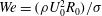 $We=(\unicode[STIX]{x1D70C}U_{0}^{2}R_{0})/\unicode[STIX]{x1D70E}$
and the solid–liquid density ratio
$We=(\unicode[STIX]{x1D70C}U_{0}^{2}R_{0})/\unicode[STIX]{x1D70E}$
and the solid–liquid density ratio
 $\unicode[STIX]{x1D71A}=\unicode[STIX]{x1D70C}_{s}/\unicode[STIX]{x1D70C}$
, which along with the other main dimensional parameters and their corresponding ranges or values have been summarized in table 1. Some variants of the Richardson number have also been used in this work and are discussed later in § 3.2.3.
$\unicode[STIX]{x1D71A}=\unicode[STIX]{x1D70C}_{s}/\unicode[STIX]{x1D70C}$
, which along with the other main dimensional parameters and their corresponding ranges or values have been summarized in table 1. Some variants of the Richardson number have also been used in this work and are discussed later in § 3.2.3.

Figure 3. Impact and descent of a
 $D_{0}=10$
mm,
$D_{0}=10$
mm,
 $T_{s}=230\,^{\circ }$
C steel sphere released from
$T_{s}=230\,^{\circ }$
C steel sphere released from
 $h_{r}=70$
cm shown at various depth ranges
$h_{r}=70$
cm shown at various depth ranges
 $z~(\text{cm})=0$
–37 (a), 44–78 (b), 78–102 (c) and 100–124 (d) inside the 2 m tank used (shown on the right). One can notice the formation of a series of distinct acoustic pinch-offs (labelled
$z~(\text{cm})=0$
–37 (a), 44–78 (b), 78–102 (c) and 100–124 (d) inside the 2 m tank used (shown on the right). One can notice the formation of a series of distinct acoustic pinch-offs (labelled
 $1\text{st}$
,
$1\text{st}$
,
 $2\text{nd}$
,
$2\text{nd}$
,
 $3\text{rd}$
), each one occurring at the depth of the sphere when the preceding pinch-off takes place (see the dashed arrows). A stable–streamlined cavity is observed for
$3\text{rd}$
), each one occurring at the depth of the sphere when the preceding pinch-off takes place (see the dashed arrows). A stable–streamlined cavity is observed for
 $t=383$
–622 ms after impact. Here,
$t=383$
–622 ms after impact. Here,
 $U_{0}=3.7~\text{m}~\text{s}^{-1}$
,
$U_{0}=3.7~\text{m}~\text{s}^{-1}$
,
 $Fr=280$
. See also supplementary movie 2 for depth range (b).
$Fr=280$
. See also supplementary movie 2 for depth range (b).
3 Qualitative results
3.1 Stable–streamlined cavity wake formation
A more detailed account of the stable–streamlined cavity formation is shown in figure 3, where a heated
 $D_{0}=10$
mm steel sphere impacts the PP1 pool at
$D_{0}=10$
mm steel sphere impacts the PP1 pool at
 $U_{0}=3.7~\text{m}~\text{s}^{-1}$
. For the impact parameters employed, the surface seal phenomenon occurs before the cavity pinches off to induce a fine spray of droplets into the cavity, which is quickly engulfed beneath the free surface (
$U_{0}=3.7~\text{m}~\text{s}^{-1}$
. For the impact parameters employed, the surface seal phenomenon occurs before the cavity pinches off to induce a fine spray of droplets into the cavity, which is quickly engulfed beneath the free surface (
 $t=33$
ms). The droplets collide with the cavity interface, distorting the cavity walls, and hence also the pinch-off point (
$t=33$
ms). The droplets collide with the cavity interface, distorting the cavity walls, and hence also the pinch-off point (
 $t=44$
ms), in the process. The formation of a subtle surface undulation (
$t=44$
ms), in the process. The formation of a subtle surface undulation (
 $\unicode[STIX]{x1D706}=O(\text{cm})$
) is also noted along the elongated cavity interface (see solid arrow), which has previously been shown by Mansoor et al. (Reference Mansoor, Marston, Vakarelski and Thoroddsen2014) to occur in the presence of wall effects. The flow of fluid parallel to the cavity interface from geometrical confinement by the tank walls has been described as a potential origin of this wave-like structure, which becomes more prominent as the severity of wall effects increases. In further agreement with their work, the necking crest of this undulation not only provides a favourable point for cavity closure (
$\unicode[STIX]{x1D706}=O(\text{cm})$
) is also noted along the elongated cavity interface (see solid arrow), which has previously been shown by Mansoor et al. (Reference Mansoor, Marston, Vakarelski and Thoroddsen2014) to occur in the presence of wall effects. The flow of fluid parallel to the cavity interface from geometrical confinement by the tank walls has been described as a potential origin of this wave-like structure, which becomes more prominent as the severity of wall effects increases. In further agreement with their work, the necking crest of this undulation not only provides a favourable point for cavity closure (
 $t=67$
ms) but also suppresses the formation of the downward-facing jet at the primary (or first) pinch-off location, following the air flow mechanism proposed by Gekle et al. (Reference Gekle, Peters, Gordillo, Van der Meer and Lohse2010).
$t=67$
ms) but also suppresses the formation of the downward-facing jet at the primary (or first) pinch-off location, following the air flow mechanism proposed by Gekle et al. (Reference Gekle, Peters, Gordillo, Van der Meer and Lohse2010).
Gekle et al. (Reference Gekle, Peters, Gordillo, Van der Meer and Lohse2010) showed that the air flow through the shrinking cavity neck (
 ${\approx}0.5$
mm in radius) can theoretically reach supersonic speeds for impact velocities as low as 1
${\approx}0.5$
mm in radius) can theoretically reach supersonic speeds for impact velocities as low as 1
 $\text{m}~\text{s}^{-1}$
. The Bernoulli suction effect created by the high-speed air flow diminished the pressure at the cavity neck to a minimum of 0.6 Pa when the Mach number reached unity. This reduction in pressure was reported to be sufficiently strong to deform the cavity shape and produce a visible ‘kink’ at the neck. In the experiments with wall effects by Mansoor et al. (Reference Mansoor, Marston, Vakarelski and Thoroddsen2014) (as also present in this study), the effects reported by Gekle et al. (Reference Gekle, Peters, Gordillo, Van der Meer and Lohse2010) were enhanced, not only producing larger ‘kinks’ at the necking region but also suppressing formation of the downward jet. The enhancement was attributed to the formation of an elongated cavity with multiple simultaneously necking regions, each of which acts to strengthen the air flow through the first wave crest. This created a choking effect following the sudden blockade after cavity pinch-off, causing the lower cavity apex to swell upward and prevent its walls from colliding radially inwards, analogous to the observation made at
$\text{m}~\text{s}^{-1}$
. The Bernoulli suction effect created by the high-speed air flow diminished the pressure at the cavity neck to a minimum of 0.6 Pa when the Mach number reached unity. This reduction in pressure was reported to be sufficiently strong to deform the cavity shape and produce a visible ‘kink’ at the neck. In the experiments with wall effects by Mansoor et al. (Reference Mansoor, Marston, Vakarelski and Thoroddsen2014) (as also present in this study), the effects reported by Gekle et al. (Reference Gekle, Peters, Gordillo, Van der Meer and Lohse2010) were enhanced, not only producing larger ‘kinks’ at the necking region but also suppressing formation of the downward jet. The enhancement was attributed to the formation of an elongated cavity with multiple simultaneously necking regions, each of which acts to strengthen the air flow through the first wave crest. This created a choking effect following the sudden blockade after cavity pinch-off, causing the lower cavity apex to swell upward and prevent its walls from colliding radially inwards, analogous to the observation made at
 $t=67$
ms in figure 3.
$t=67$
ms in figure 3.
Similarly to Grumstrup et al. (Reference Grumstrup, Keller and Belmonte2007), distinct waves having wavelengths
 $\unicode[STIX]{x1D706}=O(D_{0})$
emanate from the sphere surface as soon as the first cavity pinch-off occurs. These waves (or ripples) have been reported as being an acoustic phenomenon initiated by the pressure perturbation of the deep seal event. The crests of these waves can also act as favourable points for cavity closure, whereby the location of the first closure point always coincides with the depth of the sphere (
$\unicode[STIX]{x1D706}=O(D_{0})$
emanate from the sphere surface as soon as the first cavity pinch-off occurs. These waves (or ripples) have been reported as being an acoustic phenomenon initiated by the pressure perturbation of the deep seal event. The crests of these waves can also act as favourable points for cavity closure, whereby the location of the first closure point always coincides with the depth of the sphere (
 $H$
) when the first cavity pinch-off occurs (Mansoor et al.
Reference Mansoor, Marston, Vakarelski and Thoroddsen2014). This event, known as the first acoustic pinch-off (due to its acoustic origin), can be observed here at
$H$
) when the first cavity pinch-off occurs (Mansoor et al.
Reference Mansoor, Marston, Vakarelski and Thoroddsen2014). This event, known as the first acoustic pinch-off (due to its acoustic origin), can be observed here at
 $t=83$
ms (see the first dashed arrow), which also marks the onset of the cavity shedding regime. Both Grumstrup et al. (Reference Grumstrup, Keller and Belmonte2007) and Mansoor et al. (Reference Mansoor, Marston, Vakarelski and Thoroddsen2014) have shown the cavity to break systemically in the shedding regime but not necessarily at every acoustic wave crest in the presence of wall effects (by the latter study), due to the elongated nature of the cavity formed.
$t=83$
ms (see the first dashed arrow), which also marks the onset of the cavity shedding regime. Both Grumstrup et al. (Reference Grumstrup, Keller and Belmonte2007) and Mansoor et al. (Reference Mansoor, Marston, Vakarelski and Thoroddsen2014) have shown the cavity to break systemically in the shedding regime but not necessarily at every acoustic wave crest in the presence of wall effects (by the latter study), due to the elongated nature of the cavity formed.
A more comprehensive examination of the cavity shedding regime presented here shows the cavity to break up in a distinct sequence until a stable–streamlined state is achieved. After a series of breakups at adjacent acoustic wave crests, resulting in a continuous string of small detached bubbles (
 $t=104$
ms), a relatively larger bubble is shed off (
$t=104$
ms), a relatively larger bubble is shed off (
 $t=124$
ms) at a depth equal to the depth of the sphere when the first acoustic pinch-off occurs (see the second dashed arrow). Hence, similar in nature to the formation of the first acoustic pinch-off itself, another distinct pinch-off occurs at the crest of an acoustic wave generated by the pressure perturbation of the first acoustic pinch-off event. This sequence of events occurs repeatedly (e.g at
$t=124$
ms) at a depth equal to the depth of the sphere when the first acoustic pinch-off occurs (see the second dashed arrow). Hence, similar in nature to the formation of the first acoustic pinch-off itself, another distinct pinch-off occurs at the crest of an acoustic wave generated by the pressure perturbation of the first acoustic pinch-off event. This sequence of events occurs repeatedly (e.g at
 $t=165$
ms, see the third dashed arrow), and since the pinch-off pressure perturbations are expected to subside in succession with time, the wavelength of the acoustic waves and hence the size of the bubbles pinched off in turn is observed to decrease accordingly. This phenomenon, which can be referred to as an acoustic pinch-off cascade, reaches a stage whereby the cavity volume has shrunk considerably and the acoustic ripples induced are no longer large enough to promote any further large-scale cavity shedding (
$t=165$
ms, see the third dashed arrow), and since the pinch-off pressure perturbations are expected to subside in succession with time, the wavelength of the acoustic waves and hence the size of the bubbles pinched off in turn is observed to decrease accordingly. This phenomenon, which can be referred to as an acoustic pinch-off cascade, reaches a stage whereby the cavity volume has shrunk considerably and the acoustic ripples induced are no longer large enough to promote any further large-scale cavity shedding (
 $t\geqslant 293$
ms).
$t\geqslant 293$
ms).
It is noteworthy that with the exception of the penultimate pinch-off occurring in each acoustic pinch-off cascade shown (at
 $t=104$
ms, 140 ms, 187 ms), the formation of the downward-facing jet following all other pinch-offs is found to be suppressed entirely. This again can be attributed to the upward air flow through the topmost shrinking neck region (Gekle et al.
Reference Gekle, Peters, Gordillo, Van der Meer and Lohse2010), which is possibly strengthened by the presence of multiple simultaneously necking regions underneath on the elongated cavity interface (Mansoor et al.
Reference Mansoor, Marston, Vakarelski and Thoroddsen2014). These regions occur at acoustic wave crests in this study, and a series of close-up images from
$t=104$
ms, 140 ms, 187 ms), the formation of the downward-facing jet following all other pinch-offs is found to be suppressed entirely. This again can be attributed to the upward air flow through the topmost shrinking neck region (Gekle et al.
Reference Gekle, Peters, Gordillo, Van der Meer and Lohse2010), which is possibly strengthened by the presence of multiple simultaneously necking regions underneath on the elongated cavity interface (Mansoor et al.
Reference Mansoor, Marston, Vakarelski and Thoroddsen2014). These regions occur at acoustic wave crests in this study, and a series of close-up images from
 $t=124$
to 165 ms show this phenomenon in more detail in figure 4(a). It can be noted that since the necking region, leading to a distinct acoustic pinch-off at
$t=124$
to 165 ms show this phenomenon in more detail in figure 4(a). It can be noted that since the necking region, leading to a distinct acoustic pinch-off at
 $t=165$
ms (see the dashed arrow), has developed only marginally when the preceding (penultimate) pinch-off occurs (
$t=165$
ms (see the dashed arrow), has developed only marginally when the preceding (penultimate) pinch-off occurs (
 $t=140$
ms), the upward air flow through the neck is initially insufficient to cause the tail of the entrained cavity to swell up and prevent the cavity walls from colliding radially inwards. A downward-facing jet is hence formed at this stage (see the white arrows). This jet formation, in agreement with our reasoning, is progressively suppressed with every successive acoustic pinch-off cascade, as the last necking region in each cycle takes an increasingly shorter time period for development from the occurrence of the preceding (penultimate) cavity pinch-off above. Distortion of the cavity interface caused by droplets from these jets impacting the cavity walls can aggravate cavity shedding, as noted behind the cavity at
$t=140$
ms), the upward air flow through the neck is initially insufficient to cause the tail of the entrained cavity to swell up and prevent the cavity walls from colliding radially inwards. A downward-facing jet is hence formed at this stage (see the white arrows). This jet formation, in agreement with our reasoning, is progressively suppressed with every successive acoustic pinch-off cascade, as the last necking region in each cycle takes an increasingly shorter time period for development from the occurrence of the preceding (penultimate) cavity pinch-off above. Distortion of the cavity interface caused by droplets from these jets impacting the cavity walls can aggravate cavity shedding, as noted behind the cavity at
 $t=383$
ms in figure 3. The disturbance from droplet impacts creates an added resistance to the motion of the cavity wake, which causes it to extend for further breakups.
$t=383$
ms in figure 3. The disturbance from droplet impacts creates an added resistance to the motion of the cavity wake, which causes it to extend for further breakups.

Figure 4. (a) Series of close-up images showing the formation of the third distinct acoustic pinch-off in figure 3 at
 $t=165$
ms. A downward jet (indicated by white arrows) is emitted only from the preceding pinch-off at
$t=165$
ms. A downward jet (indicated by white arrows) is emitted only from the preceding pinch-off at
 $t=140$
ms. (b) Images at 4 ms intervals showing the pacification of acoustic ripples. The tail of the cavity becomes drawn along with the cavity wake when rippling has subdued (see last panel). (c) Comparison of cavities obtained using a Leidenfrost steel sphere (from figure 3) and a room-temperature steel sphere (
$t=140$
ms. (b) Images at 4 ms intervals showing the pacification of acoustic ripples. The tail of the cavity becomes drawn along with the cavity wake when rippling has subdued (see last panel). (c) Comparison of cavities obtained using a Leidenfrost steel sphere (from figure 3) and a room-temperature steel sphere (
 $D_{0}=10$
mm,
$D_{0}=10$
mm,
 $U_{0}=3.7~\text{m}~\text{s}^{-1}$
,
$U_{0}=3.7~\text{m}~\text{s}^{-1}$
,
 $T_{s}=22\,^{\circ }$
C) at
$T_{s}=22\,^{\circ }$
C) at
 $z=60.7$
cm. The acoustic ripples do not subdue in the latter case, where a physical contact line is present around the sphere equator.
$z=60.7$
cm. The acoustic ripples do not subdue in the latter case, where a physical contact line is present around the sphere equator.
A crucial phenomenon in the formation of a stable–streamlined cavity once the acoustic ripples have subdued (
 $t=293$
ms) is the continued suppression of the downward-facing jet arising from the local flow conditions around the colliding cavity-wall junction. Given that the hydrostatic pressure increases with depth, the cavity walls become increasingly prone to collapse as the sphere descends towards the bottom of the tank. This in turn can drive the formation of a downward-facing jet (Gekle et al.
Reference Gekle, Gordillo, Van der Meer and Lohse2009) from the colliding junction at the tail of the entrained cavity. However, since the tail, breaking up at acoustic wave crests, becomes drawn along with the cavity wake as soon as the acoustic ripples subdue (see the example in figure 4
b), the radial focusing effect from the hydrostatic pressure can be overcome by a more dominant skin-friction drag effect induced by shear stresses at the interface of this trailing cavity junction. In essence, we propose that the downward motion of the jet base (at the cavity apex), which dictates the radial collision of the cavity walls, is prevented by the upward pull of skin friction at their junction about the axis. This inhibits the fluid around the junction from acquiring a downward acceleration which otherwise feeds jet formation (Gekle et al.
Reference Gekle, Gordillo, Van der Meer and Lohse2009).
$t=293$
ms) is the continued suppression of the downward-facing jet arising from the local flow conditions around the colliding cavity-wall junction. Given that the hydrostatic pressure increases with depth, the cavity walls become increasingly prone to collapse as the sphere descends towards the bottom of the tank. This in turn can drive the formation of a downward-facing jet (Gekle et al.
Reference Gekle, Gordillo, Van der Meer and Lohse2009) from the colliding junction at the tail of the entrained cavity. However, since the tail, breaking up at acoustic wave crests, becomes drawn along with the cavity wake as soon as the acoustic ripples subdue (see the example in figure 4
b), the radial focusing effect from the hydrostatic pressure can be overcome by a more dominant skin-friction drag effect induced by shear stresses at the interface of this trailing cavity junction. In essence, we propose that the downward motion of the jet base (at the cavity apex), which dictates the radial collision of the cavity walls, is prevented by the upward pull of skin friction at their junction about the axis. This inhibits the fluid around the junction from acquiring a downward acceleration which otherwise feeds jet formation (Gekle et al.
Reference Gekle, Gordillo, Van der Meer and Lohse2009).
The cavity finally assumes a completely stable–streamlined state (
 $t=383$
–622 ms) when the acoustic rippling along its interface and the downward jet formation within (including any interfacial distortion created in turn) have subdued to a negligible extent. The vapour layer, which encapsulates the sphere to prevent any physical contact with the liquid and hence create an ultimate non-wetting scenario (Marston et al.
Reference Marston, Vakarelski and Thoroddsen2012), results in the formation of extremely smooth cavities, essential in achieving such stability. This can be confirmed by repeating the same experiment with a room-temperature sphere (see figure 4
c), in which case the rippling is much more pronounced and does not subdue in the presence of a physical contact line around the sphere equator. The contact line pinning here promotes turbulence in the interfacial boundary layer along the cavity, resulting in ripples having wavelengths
$t=383$
–622 ms) when the acoustic rippling along its interface and the downward jet formation within (including any interfacial distortion created in turn) have subdued to a negligible extent. The vapour layer, which encapsulates the sphere to prevent any physical contact with the liquid and hence create an ultimate non-wetting scenario (Marston et al.
Reference Marston, Vakarelski and Thoroddsen2012), results in the formation of extremely smooth cavities, essential in achieving such stability. This can be confirmed by repeating the same experiment with a room-temperature sphere (see figure 4
c), in which case the rippling is much more pronounced and does not subdue in the presence of a physical contact line around the sphere equator. The contact line pinning here promotes turbulence in the interfacial boundary layer along the cavity, resulting in ripples having wavelengths
 $O(\text{mm})$
downstream (Brennen Reference Brennen1970; Marston et al.
Reference Marston, Vakarelski and Thoroddsen2012). It is most likely that these ripples interfere with acoustic rippling to result in the distinct wave pattern observed at the tail of the cavity. This implies that the overall volume oscillations of the cavity instigated by the pressure perturbations of the pinch-off events are affected, which could be a potential research topic for future studies.
$O(\text{mm})$
downstream (Brennen Reference Brennen1970; Marston et al.
Reference Marston, Vakarelski and Thoroddsen2012). It is most likely that these ripples interfere with acoustic rippling to result in the distinct wave pattern observed at the tail of the cavity. This implies that the overall volume oscillations of the cavity instigated by the pressure perturbations of the pinch-off events are affected, which could be a potential research topic for future studies.
It is worth mentioning that since the Leidenfrost sphere continuously vaporizes the surrounding liquid to maintain a vapour jacket, the steadiness of cavity volume noted in the stable–streamlined state (see § 4.3.1) can lead to a slight increase in the internal cavity pressure. An estimate of this vapour influx can be obtained by analysing videos showing the cooling process of a non-moving Leidenfrost sphere (e.g. see supplemental video 1 in Vakarelski et al. (Reference Vakarelski, Marston, Chan and Thoroddsen2011)) and measuring the frequency and average volume of vapour bubbles formed on the sphere. For a
 $D_{0}=20$
mm steel sphere, the PP1 vapour produced was estimated to account for 5 % of the streamlined cavity volume after a descent of 1 m. This can help to mitigate the resonant volume oscillations of the cavity, instigated by the pressure perturbations of the pinch-off events, and suppress the downward jet formation by preventing collapse at the trailing cavity-wall junction. We also note that PP1 vapour has a much larger density than air and may cause the air to purge from the tail first.
$D_{0}=20$
mm steel sphere, the PP1 vapour produced was estimated to account for 5 % of the streamlined cavity volume after a descent of 1 m. This can help to mitigate the resonant volume oscillations of the cavity, instigated by the pressure perturbations of the pinch-off events, and suppress the downward jet formation by preventing collapse at the trailing cavity-wall junction. We also note that PP1 vapour has a much larger density than air and may cause the air to purge from the tail first.
With increasing hydrostatic pressures as the sphere descends further, the (steady-state) skin-friction drag effect (see § 4.3) at the liquid–vapour interface can no longer prevent the cavity walls from colliding beyond a certain threshold depth (
 $z=89$
cm in the present case). This revives the formation of the downward jet (
$z=89$
cm in the present case). This revives the formation of the downward jet (
 $t=622$
ms, figure 3
d), which impacts the cavity interface to cause destabilization. The cavity then starts to shed off in a haphazard manner, leaving scattered clouds of small bubbles in the cavity trail (
$t=622$
ms, figure 3
d), which impacts the cavity interface to cause destabilization. The cavity then starts to shed off in a haphazard manner, leaving scattered clouds of small bubbles in the cavity trail (
 $t=908$
ms).
$t=908$
ms).
A comparison of stable–streamlined cavities obtained using
 $D_{0}=10$
mm (a) steel and (b) tungsten carbide spheres for increasing impact velocities ranging from
$D_{0}=10$
mm (a) steel and (b) tungsten carbide spheres for increasing impact velocities ranging from
 $U_{0}=3.43$
to
$U_{0}=3.43$
to
 $4.43~\text{m}~\text{s}^{-1}$
is presented in figure 5. As observed, the stable cavity assumes approximately constant diameter-to-length ratios of
$4.43~\text{m}~\text{s}^{-1}$
is presented in figure 5. As observed, the stable cavity assumes approximately constant diameter-to-length ratios of
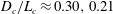
 $D_{c}/L_{c}\approx 0.30$
and 0.21 in (a) and (b), which result from steady descent velocities of
$D_{c}/L_{c}\approx 0.30$
and 0.21 in (a) and (b), which result from steady descent velocities of
 $U_{t}\approx 1$
and
$U_{t}\approx 1$
and
 $1.6~\text{m}~\text{s}^{-1}$
for
$1.6~\text{m}~\text{s}^{-1}$
for
 $\unicode[STIX]{x1D70C}_{s}/\unicode[STIX]{x1D70C}=4.54$
and 8.70 (from sphere trajectory measurements, see § 4 for details) respectively, when the stable configuration is achieved. The increase in impact velocities hence does not affect the dimensions of the stable cavity for a given sphere size and density but is generally noted to result in increasing depths
$\unicode[STIX]{x1D70C}_{s}/\unicode[STIX]{x1D70C}=4.54$
and 8.70 (from sphere trajectory measurements, see § 4 for details) respectively, when the stable configuration is achieved. The increase in impact velocities hence does not affect the dimensions of the stable cavity for a given sphere size and density but is generally noted to result in increasing depths
 $z_{s}$
at which the stable cavity configuration is first achieved, due to a correspondingly larger initial cavity volume entrained (Aristoff et al.
Reference Aristoff, Truscott, Techet and Bush2010).
$z_{s}$
at which the stable cavity configuration is first achieved, due to a correspondingly larger initial cavity volume entrained (Aristoff et al.
Reference Aristoff, Truscott, Techet and Bush2010).

Figure 5. Stable–streamlined cavities obtained using
 $D_{0}=10$
mm (a) steel (
$D_{0}=10$
mm (a) steel (
 $\unicode[STIX]{x1D71A}=4.54$
,
$\unicode[STIX]{x1D71A}=4.54$
,
 $U_{t}=1~\text{m}~\text{s}^{-1}$
) and (b) tungsten carbide spheres (
$U_{t}=1~\text{m}~\text{s}^{-1}$
) and (b) tungsten carbide spheres (
 $\unicode[STIX]{x1D71A}=8.70$
,
$\unicode[STIX]{x1D71A}=8.70$
,
 $U_{t}=1.6$
 $\text{m}~\text{s}^{-1}$
) for increasing impact velocities of
$\text{m}~\text{s}^{-1}$
) for increasing impact velocities of
 $U_{0}=3.43$
, 3.70, 3.96, 4.20 and
$U_{0}=3.43$
, 3.70, 3.96, 4.20 and
 $4.43~\text{m}~\text{s}^{-1}$
(corresponding to release heights of
$4.43~\text{m}~\text{s}^{-1}$
(corresponding to release heights of
 $h_{r}=60$
, 70, 80, 90 and 100 cm respectively). The depth
$h_{r}=60$
, 70, 80, 90 and 100 cm respectively). The depth
 $z_{s}$
(cm) indicates the distance from the free surface where the stable cavity state is first achieved in each case. Here,
$z_{s}$
(cm) indicates the distance from the free surface where the stable cavity state is first achieved in each case. Here,
 $D_{c}$
and
$D_{c}$
and
 $L_{c}$
are the cavity diameter and length measurements respectively;
$L_{c}$
are the cavity diameter and length measurements respectively;
 $Fr=240$
–400.
$Fr=240$
–400.

Figure 6. Stable and unstable cavities created by the impact of (a) steel and (b) tungsten carbide spheres at
 $U_{0}=3.96~\text{m}~\text{s}^{-1}$
(
$U_{0}=3.96~\text{m}~\text{s}^{-1}$
(
 $h_{r}=80$
mm) for increasing sizes in the range of
$h_{r}=80$
mm) for increasing sizes in the range of
 $D_{0}=10{-}40$
mm and
$D_{0}=10{-}40$
mm and
 $Fr=40{-}320$
. The cavities become increasingly unstable as the sphere size increases.
$Fr=40{-}320$
. The cavities become increasingly unstable as the sphere size increases.
Figure 6 explores the effect of sphere size in addition to density on the state and dimensions of the cavity obtained for a fixed impact velocity of
 $U_{0}=3.96~\text{m}~\text{s}^{-1}$
. Stable-state cavities are obtainable for increasing sphere sizes until
$U_{0}=3.96~\text{m}~\text{s}^{-1}$
. Stable-state cavities are obtainable for increasing sphere sizes until
 $D_{0}=25$
mm, with self-similar cavity diameter-to-length ratios of
$D_{0}=25$
mm, with self-similar cavity diameter-to-length ratios of
 $D_{c}/L_{c}\approx 0.30,0.21$
and cavity-to-sphere diameter ratios of
$D_{c}/L_{c}\approx 0.30,0.21$
and cavity-to-sphere diameter ratios of
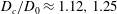 $D_{c}/D_{0}\approx 1.12,1.25$
for (a) steel and (b) tungsten carbide spheres respectively. For cavities entrained by larger spheres (
$D_{c}/D_{0}\approx 1.12,1.25$
for (a) steel and (b) tungsten carbide spheres respectively. For cavities entrained by larger spheres (
 $D_{0}=30$
and 40 mm), the skin-friction drag effect becomes increasingly insufficient in preventing collapse at the trailing cavity junction. The continual downward jet formation as a result ultimately causes cavity destabilization regardless of the increasing influence of wall effects to produce highly wrinkled cavities shedding off at a rapid rate.
$D_{0}=30$
and 40 mm), the skin-friction drag effect becomes increasingly insufficient in preventing collapse at the trailing cavity junction. The continual downward jet formation as a result ultimately causes cavity destabilization regardless of the increasing influence of wall effects to produce highly wrinkled cavities shedding off at a rapid rate.
3.2 Helical cavity wake formation

Figure 7. (a) Dual-cavity structure and (b) helical cavity wake formation by the impact of a
 $D_{0}=20$
mm and 30 mm steel sphere released from
$D_{0}=20$
mm and 30 mm steel sphere released from
 $h_{r}=90$
and 100 cm respectively. Close-up views at
$h_{r}=90$
and 100 cm respectively. Close-up views at
 $t=15$
, 20 and 30 ms from impact are shown in (c) and (d) in the same order; (a,c)
$t=15$
, 20 and 30 ms from impact are shown in (c) and (d) in the same order; (a,c)
 $U_{0}=4.20~\text{m}~\text{s}^{-1}$
,
$U_{0}=4.20~\text{m}~\text{s}^{-1}$
,
 $Fr=180$
; (b,d)
$Fr=180$
; (b,d)
 $U_{0}=4.43~\text{m}~\text{s}^{-1}$
,
$U_{0}=4.43~\text{m}~\text{s}^{-1}$
,
 $Fr=133$
.
$Fr=133$
.
In addition to the formation of unstable and stable–streamlined cavities, we also note the formation of a third and new form of cavity characterized by a helical nature, which finds its roots in the dual-cavity structure reported previously by Marston et al. (Reference Marston, Vakarelski and Thoroddsen2012). This structure, which is shown forming in figure 7(a) with close-up views in (c), results in a distinct cavity pinch-off of its own (
 $t=30$
ms) and is described as having sensitive dependence on the sphere temperature and impact speed. Marston et al. (Reference Marston, Vakarelski and Thoroddsen2012) ascribed the origin of the dual-cavity structure to the vapour layer not being able to fully form within the time scale of one radius penetration, i.e
$t=30$
ms) and is described as having sensitive dependence on the sphere temperature and impact speed. Marston et al. (Reference Marston, Vakarelski and Thoroddsen2012) ascribed the origin of the dual-cavity structure to the vapour layer not being able to fully form within the time scale of one radius penetration, i.e
 $tU_{0}/R_{0}=1$
. The presence of a physical contact line observed around the sphere equator initiated nucleate boiling and was shed backwards by the advancing vapour layer until the sphere was encapsulated entirely. However, since the presence of a vapour layer around the entire bottom hemisphere was indicated with marked uncertainty in the images recorded, the origin of the dual-cavity structure could not be fully understood in their study. For hot spheres impacting the liquid medium at comparatively higher velocities (
$tU_{0}/R_{0}=1$
. The presence of a physical contact line observed around the sphere equator initiated nucleate boiling and was shed backwards by the advancing vapour layer until the sphere was encapsulated entirely. However, since the presence of a vapour layer around the entire bottom hemisphere was indicated with marked uncertainty in the images recorded, the origin of the dual-cavity structure could not be fully understood in their study. For hot spheres impacting the liquid medium at comparatively higher velocities (
 $U_{0}=6.25~\text{m}~\text{s}^{-1}$
), the formation of asymmetric cavities comprising three or four columns of liquid converging towards the cavity centre was also shown using top-down views. The liquid columns were attributed to the contact of the cavity wall with the hot sphere, but the origin of the instability resulting in their formation could not be explained.
$U_{0}=6.25~\text{m}~\text{s}^{-1}$
), the formation of asymmetric cavities comprising three or four columns of liquid converging towards the cavity centre was also shown using top-down views. The liquid columns were attributed to the contact of the cavity wall with the hot sphere, but the origin of the instability resulting in their formation could not be explained.
In the parameter space of experiments conducted at constant
 $T_{s}$
in this study, the series of events occurring before a dual-structure cavity forms (i.e
$T_{s}$
in this study, the series of events occurring before a dual-structure cavity forms (i.e
 $t\leqslant 10$
ms in figure 7
a) are observed to occur indefinitely (as shown in figure 7
b) above a threshold impact Reynolds number (see figure 12). The cavity is noted to develop evident ridges or streaks (see the close-ups in figure 7
d) which stem from the sphere surface and follow random trajectories about its equator as it descends into the tank. Columns of liquid very similar to those observed by Marston et al. (Reference Marston, Vakarelski and Thoroddsen2012) are noted to originate from each of these ridges, which break up while moving radially inwards to induce a fine and continuous spray of droplets within the cavity. The cavity collapses asymmetrically at a sizable section at once midway along its length (
$t\leqslant 10$
ms in figure 7
a) are observed to occur indefinitely (as shown in figure 7
b) above a threshold impact Reynolds number (see figure 12). The cavity is noted to develop evident ridges or streaks (see the close-ups in figure 7
d) which stem from the sphere surface and follow random trajectories about its equator as it descends into the tank. Columns of liquid very similar to those observed by Marston et al. (Reference Marston, Vakarelski and Thoroddsen2012) are noted to originate from each of these ridges, which break up while moving radially inwards to induce a fine and continuous spray of droplets within the cavity. The cavity collapses asymmetrically at a sizable section at once midway along its length (
 $t\approx 60$
ms), following which the ridges become arranged at equidistant circumferential locations about the sphere equator and begin to rotate synchronously (in an anticlockwise direction in this case) to form a helical cavity wake. The final direction of the helical cavity rotation stems from the superposition of the interfacial ridge movements at the time of cavity collapse. Hence, no two impacts conducted for similar conditions necessarily result in the same direction of cavity rotation.
$t\approx 60$
ms), following which the ridges become arranged at equidistant circumferential locations about the sphere equator and begin to rotate synchronously (in an anticlockwise direction in this case) to form a helical cavity wake. The final direction of the helical cavity rotation stems from the superposition of the interfacial ridge movements at the time of cavity collapse. Hence, no two impacts conducted for similar conditions necessarily result in the same direction of cavity rotation.
Figure 8(a) shows a series of close-up images as an example of a helical cavity wake in clockwise rotation formed for the same impact conditions as employed in figure 7(b). The magnified views show the rotating ridges to outline and form three distinct interfacial sections which are superimposed with red, blue and green colour maps in (b) for better viewing. Each section has a slanted and twisted shape which becomes narrow towards its apex, and the cavity sheds off rapidly from these apexes in a periodic manner to form a spiralling trail of small bubbles. A columnar spray of droplets is again noted from each of the three ridges; however, due to the helical symmetry of the cavity here, the drops mostly collide with each other along the vertical axis rather than the cavity walls. We find the helical cavity wake to rotate continuously in this manner until the entire cavity is eventually shed off.
3.2.1 Studies on flow past spheres
Explaining the helical nature of the cavity wake observed requires an understanding of the flow structures produced around and in the wake of a Leidenfrost sphere in contact line cases. However, given the complexity of the problem and the fact that no study has investigated this phenomenon so far, one can form an analogy with the much-studied flow structures produced by a fully submerged sphere in a homogeneous fluid stream for clarification and inspiration. The contact line and gaseous wake of a Leidenfrost sphere in this respect are relevant to the boundary layer separation at the trailing edge of a fully submerged sphere and the recirculation zone present in its wake respectively. We will therefore outline the many studies on this subject and how they relate directly to the observations made in this study.

Figure 8. (a) Images at 5 ms intervals of a helical cavity wake created by the impact of a
 $D_{0}=30$
mm steel sphere from
$D_{0}=30$
mm steel sphere from
 $h_{r}=100$
cm. The first image is taken 138 ms after impact at a depth of
$h_{r}=100$
cm. The first image is taken 138 ms after impact at a depth of
 $z=57$
cm. The ridges noted on the cavity surface outline and form three distinct interfacial regions which rotate synchronously in a clockwise direction. The yellow stars (at
$z=57$
cm. The ridges noted on the cavity surface outline and form three distinct interfacial regions which rotate synchronously in a clockwise direction. The yellow stars (at
 $z=59$
cm) mark the location of one specific ridge as it advects downstream in the sphere wake. (b) Red, blue and green colour maps superimposed individually on each of the three rotating interfacial sections. Here,
$z=59$
cm) mark the location of one specific ridge as it advects downstream in the sphere wake. (b) Red, blue and green colour maps superimposed individually on each of the three rotating interfacial sections. Here,
 $U_{0}=4.43~\text{m}~\text{s}^{-1}$
,
$U_{0}=4.43~\text{m}~\text{s}^{-1}$
,
 $Fr=133$
,
$Fr=133$
,
 $St=0.27$
. See also supplementary movie 3.
$St=0.27$
. See also supplementary movie 3.
Even though many studies have investigated the flow past a sphere in a homogeneous fluid, there still exists some disagreement on the existence of different instability modes with respect to increasing Reynolds number regimes. For
 $Re<24$
(Taneda 1956), a laminar flow is observed with no separation from the sphere surface, while for
$Re<24$
(Taneda 1956), a laminar flow is observed with no separation from the sphere surface, while for
 $Re=24$
–
$Re=24$
–
 $200$
(Nakamura Reference Nakamura1976), the flow recirculates in a toroidal vortex behind the sphere in an axisymmetric and steady manner. When
$200$
(Nakamura Reference Nakamura1976), the flow recirculates in a toroidal vortex behind the sphere in an axisymmetric and steady manner. When
 $Re=211{-}270$
(Johnson & Patel Reference Johnson and Patel1999), the flow remains steady but loses its axial symmetry as the toroidal vortex gets tilted, shifting the recirculating region to one side. The flow, however, does preserve a planar symmetry, and a pair of streamwise vortices are noted to extend downstream without shedding. For a higher regime of
$Re=211{-}270$
(Johnson & Patel Reference Johnson and Patel1999), the flow remains steady but loses its axial symmetry as the toroidal vortex gets tilted, shifting the recirculating region to one side. The flow, however, does preserve a planar symmetry, and a pair of streamwise vortices are noted to extend downstream without shedding. For a higher regime of
 $Re=280$
–375, the flow assumes an unsteady planar-symmetric nature whereby the vortical structure is composed of hairpin vortices being shed in a periodic manner with a constant orientation.
$Re=280$
–375, the flow assumes an unsteady planar-symmetric nature whereby the vortical structure is composed of hairpin vortices being shed in a periodic manner with a constant orientation.

Figure 9. Strouhal number versus Reynolds number for the shear-layer (high-frequency) and spiral (low-frequency) instabilities from past studies in comparison with the present results.
For
 $Re=400$
–
$Re=400$
–
 $800$
, a distinct spiral-instability mode associated with large-scale vortex shedding is observed (Chomaz et al.
Reference Chomaz, Bonneton and Hopfinger1993), which is related to the azimuthal rotation of the recirculation zone and hence of the separation line. The spiral mode is reported as being locked with the Kelvin–Helmholtz instability in this regime since the Strouhal number (a dimensionless frequency measure) of each instability varies identically with the Reynolds number. The wake structure corresponding to this phenomenon has been described as a spiral of vortex loops emitted regularly behind the sphere, whereby the vortex shedding occurs sinuously, resulting in a progressive wave-like motion of wavelength
$800$
, a distinct spiral-instability mode associated with large-scale vortex shedding is observed (Chomaz et al.
Reference Chomaz, Bonneton and Hopfinger1993), which is related to the azimuthal rotation of the recirculation zone and hence of the separation line. The spiral mode is reported as being locked with the Kelvin–Helmholtz instability in this regime since the Strouhal number (a dimensionless frequency measure) of each instability varies identically with the Reynolds number. The wake structure corresponding to this phenomenon has been described as a spiral of vortex loops emitted regularly behind the sphere, whereby the vortex shedding occurs sinuously, resulting in a progressive wave-like motion of wavelength
 $\unicode[STIX]{x1D706}$
. For
$\unicode[STIX]{x1D706}$
. For
 $Re>800$
, the two instabilities become unlocked while coexisting simultaneously (Möller Reference Möller1938; Cometta Reference Cometta1957; Kim & Durbin Reference Kim and Durbin1988; Sakamoto & Haniu Reference Sakamoto and Haniu1990) until the maximum investigated value of
$Re>800$
, the two instabilities become unlocked while coexisting simultaneously (Möller Reference Möller1938; Cometta Reference Cometta1957; Kim & Durbin Reference Kim and Durbin1988; Sakamoto & Haniu Reference Sakamoto and Haniu1990) until the maximum investigated value of
 $Re=6\times 10^{4}$
. This is represented by a bifurcation of their frequencies (see figure 9) following
$Re=6\times 10^{4}$
. This is represented by a bifurcation of their frequencies (see figure 9) following
 $St=fD_{0}/U_{\infty }\sim Re^{1/2}$
for the small-scale Kelvin–Helmholtz instability (high-frequency mode, where
$St=fD_{0}/U_{\infty }\sim Re^{1/2}$
for the small-scale Kelvin–Helmholtz instability (high-frequency mode, where
 $f$
is the instability frequency and
$f$
is the instability frequency and
 $U_{\infty }$
is the undisturbed flow velocity) and
$U_{\infty }$
is the undisturbed flow velocity) and
 $St=D_{0}/\unicode[STIX]{x1D706}\sim 0.2$
for the large-scale spiral instability (low-frequency mode).
$St=D_{0}/\unicode[STIX]{x1D706}\sim 0.2$
for the large-scale spiral instability (low-frequency mode).
The spiral-instability mode was first speculated by Achenbach (Reference Achenbach1974), who recorded simultaneous signals from four hot-wire probes attached to the sphere surface. For
 $Re=6\times 10^{3}$
–
$Re=6\times 10^{3}$
–
 $3\times 10^{5}$
, the signals showed a phase shift, which suggested that the vortex separation occurred at a point that rotates around the sphere periodically with the vortex shedding frequency (
$3\times 10^{5}$
, the signals showed a phase shift, which suggested that the vortex separation occurred at a point that rotates around the sphere periodically with the vortex shedding frequency (
 $St=0.125$
–
$St=0.125$
–
 $0.2$
), to possibly produce a helical wake configuration. This phenomenon was not found to occur beyond the upper critical Reynolds number
$0.2$
), to possibly produce a helical wake configuration. This phenomenon was not found to occur beyond the upper critical Reynolds number
 $Re>3.7\times 10^{5}$
(Achenbach Reference Achenbach1972), i.e. in the supercritical regime, whereby the boundary layer transitions from laminar to turbulent flow, shifting downstream in the process to result in a sharp decrease in the drag coefficient. Moreover, no signal was recorded below
$Re>3.7\times 10^{5}$
(Achenbach Reference Achenbach1972), i.e. in the supercritical regime, whereby the boundary layer transitions from laminar to turbulent flow, shifting downstream in the process to result in a sharp decrease in the drag coefficient. Moreover, no signal was recorded below
 $Re=6\times 10^{3}$
, which is much higher than the spiral-instability onset of
$Re=6\times 10^{3}$
, which is much higher than the spiral-instability onset of
 $Re=400$
noted by Chomaz et al. (Reference Chomaz, Bonneton and Hopfinger1993). In contrast, Sakamoto & Haniu (Reference Sakamoto and Haniu1990), who conducted further experiments utilizing hot-wire measurements and flow visualization, showed that the shedding point of large-scale vortices begins to rotate slowly and irregularly about the streamwise axis of the sphere, starting at
$Re=400$
noted by Chomaz et al. (Reference Chomaz, Bonneton and Hopfinger1993). In contrast, Sakamoto & Haniu (Reference Sakamoto and Haniu1990), who conducted further experiments utilizing hot-wire measurements and flow visualization, showed that the shedding point of large-scale vortices begins to rotate slowly and irregularly about the streamwise axis of the sphere, starting at
 $Re=480$
. A similar observation was also reported in the work of Taneda (Reference Taneda1978) for
$Re=480$
. A similar observation was also reported in the work of Taneda (Reference Taneda1978) for
 $Re=10^{4}$
–
$Re=10^{4}$
–
 $3.8\times 10^{5}$
with
$3.8\times 10^{5}$
with
 $St\approx 0.2$
in an investigation regime of
$St\approx 0.2$
in an investigation regime of
 $Re=10^{4}$
–
$Re=10^{4}$
–
 $10^{6}$
. In comparison to these experimental studies where the spheres were kept fixed with respect to the moving fluid stream, Magarvey & Bishop (Reference Magarvey and Bishop1961) investigated wake structures behind falling spheres, as also used in this study. Their results for Strouhal numbers calculated from the vortex shedding frequencies in the range
$10^{6}$
. In comparison to these experimental studies where the spheres were kept fixed with respect to the moving fluid stream, Magarvey & Bishop (Reference Magarvey and Bishop1961) investigated wake structures behind falling spheres, as also used in this study. Their results for Strouhal numbers calculated from the vortex shedding frequencies in the range
 $Re=350$
–
$Re=350$
–
 $500$
(see figure 9) are not found to be in good agreement with fixed sphere studies. This has been reasoned to be due to the ability of the falling spheres in reacting to the changing flow forces by displacement, which can result in different hydrodynamic forces and wake formation in comparison to fixed sphere cases.
$500$
(see figure 9) are not found to be in good agreement with fixed sphere studies. This has been reasoned to be due to the ability of the falling spheres in reacting to the changing flow forces by displacement, which can result in different hydrodynamic forces and wake formation in comparison to fixed sphere cases.
A number of numerical studies have also investigated flow over spheres to further understand the vortex shedding mechanisms observed in experiments. Tomboulidesn, Orszag & Karniadakis (Reference Tomboulidesn, Orszag and Karniadakis1993) performed direct numerical simulations (DNS) and large eddy simulations (LES) to show that two distinct instability frequencies are indeed present at
 $Re=1000$
and
$Re=1000$
and
 $2\times 10^{4}$
. More recently, Constantinescu & Squires (Reference Constantinescu and Squires2004) investigated flows in both subcritical and supercritical regimes spanning
$2\times 10^{4}$
. More recently, Constantinescu & Squires (Reference Constantinescu and Squires2004) investigated flows in both subcritical and supercritical regimes spanning
 $Re=10^{4}$
–
$Re=10^{4}$
–
 $10^{6}$
, using detached-eddy simulations. For subcritical flows, the wake was shown to develop a helical-like vortical structure as the azimuthal angles at which the vortices were formed and shed varied strongly with time. In supercritical cases, the vortices were shed periodically with a single dominant frequency of
$10^{6}$
, using detached-eddy simulations. For subcritical flows, the wake was shown to develop a helical-like vortical structure as the azimuthal angles at which the vortices were formed and shed varied strongly with time. In supercritical cases, the vortices were shed periodically with a single dominant frequency of
 $St=1.3$
while appearing to be locked at certain azimuthal locations for long intervals of time. This was in contrast to the experimental results of Taneda (Reference Taneda1978) and Achenbach (Reference Achenbach1974), who did not notice any periodic vortex shedding beyond the critical Reynolds number. A helical-like wake configuration was also obtained by Rodríguez et al. (Reference Rodríguez, Borell, Lehmkuhl, Perez Segarra and Oliva2011, Reference Rodríguez, Lehmkuhl, Borrell and Oliva2013) in the subcritical regime (
$St=1.3$
while appearing to be locked at certain azimuthal locations for long intervals of time. This was in contrast to the experimental results of Taneda (Reference Taneda1978) and Achenbach (Reference Achenbach1974), who did not notice any periodic vortex shedding beyond the critical Reynolds number. A helical-like wake configuration was also obtained by Rodríguez et al. (Reference Rodríguez, Borell, Lehmkuhl, Perez Segarra and Oliva2011, Reference Rodríguez, Lehmkuhl, Borrell and Oliva2013) in the subcritical regime (
 $Re=3700,10^{4}$
) using DNS, which was shown to result from the shedding of large-scale vortices (
$Re=3700,10^{4}$
) using DNS, which was shown to result from the shedding of large-scale vortices (
 $St=0.215$
) at random azimuthal locations in the shear layer. The vortices, however, moved downstream without any azimuthal circulation, indicating that the helical pattern formed primarily from the way in which the vortices were shed in time. The LES results of Yun, Kim & Choi (Reference Yun, Kim and Choi2006) also showed the vortical structures to follow nearly straight paths downstream. They suggested the observed helical structure to be closely related to changes in the azimuthal wall-pressure distribution of the sphere with time. The wall pressure was shown to convect azimuthally at an almost constant velocity to produce a tilted vortical structure in time and, consequently, a helical wake configuration.
$St=0.215$
) at random azimuthal locations in the shear layer. The vortices, however, moved downstream without any azimuthal circulation, indicating that the helical pattern formed primarily from the way in which the vortices were shed in time. The LES results of Yun, Kim & Choi (Reference Yun, Kim and Choi2006) also showed the vortical structures to follow nearly straight paths downstream. They suggested the observed helical structure to be closely related to changes in the azimuthal wall-pressure distribution of the sphere with time. The wall pressure was shown to convect azimuthally at an almost constant velocity to produce a tilted vortical structure in time and, consequently, a helical wake configuration.
Similarly to these studies, the azimuthal locations of ridges in the helical cavity wakes formed in our study are noted as being fixed with respect to the laboratory frame as they advect downstream (e.g. see the yellow marker in figure 8
a). This indicates that the helical cavity structure arises essentially from the rotation of ridges about the sphere surface. Using visual measurements to obtain the ridge rotation frequencies
 $f_{r}$
, the corresponding Strouhal numbers
$f_{r}$
, the corresponding Strouhal numbers
 $St=f_{r}D_{0}/U_{i}$
(where
$St=f_{r}D_{0}/U_{i}$
(where
 $U_{i}$
is the instantaneous sphere velocity) are found to range between
$U_{i}$
is the instantaneous sphere velocity) are found to range between
 $St=0.22$
and
$St=0.22$
and
 $0.30$
for
$0.30$
for
 $Re\equiv Re_{i}=(\unicode[STIX]{x1D70C}U_{i}D_{0})/\unicode[STIX]{x1D707}=1.4\times 10^{5}$
–
$Re\equiv Re_{i}=(\unicode[STIX]{x1D70C}U_{i}D_{0})/\unicode[STIX]{x1D707}=1.4\times 10^{5}$
–
 $2.4\times 10^{5}$
(see figure 9). Even though the spheres in this study are trailed by a gaseous cavity, where a recirculation zone is present otherwise for spheres in a homogeneous fluid, these Strouhal numbers are still close to
$2.4\times 10^{5}$
(see figure 9). Even though the spheres in this study are trailed by a gaseous cavity, where a recirculation zone is present otherwise for spheres in a homogeneous fluid, these Strouhal numbers are still close to
 $St\approx 0.2$
reported for the spiral-instability mode in homogeneous flow cases (Achenbach Reference Achenbach1974; Taneda Reference Taneda1978). Since the flow past spheres for the range of Reynolds numbers employed here has been shown by these studies to comprise a spiral-instability mode, it is possible for the corresponding large-scale flow structures produced around the sphere to affect the shape of the cavity wake and hence its shedding characteristics accordingly. Although one might expect the flow forces resulting from the spiral instability to bring about rotation in the free falling sphere itself, repeating experiments with marked spheres and front lighting showed no indication of spinning in the close-up videos recorded.
$St\approx 0.2$
reported for the spiral-instability mode in homogeneous flow cases (Achenbach Reference Achenbach1974; Taneda Reference Taneda1978). Since the flow past spheres for the range of Reynolds numbers employed here has been shown by these studies to comprise a spiral-instability mode, it is possible for the corresponding large-scale flow structures produced around the sphere to affect the shape of the cavity wake and hence its shedding characteristics accordingly. Although one might expect the flow forces resulting from the spiral instability to bring about rotation in the free falling sphere itself, repeating experiments with marked spheres and front lighting showed no indication of spinning in the close-up videos recorded.

Figure 10. (a) Images with front lighting showing the early stages of penetration of a
 $D_{0}=30$
mm steel sphere in the formation of a helical cavity wake. (b) Close-up images of the right hemisphere for
$D_{0}=30$
mm steel sphere in the formation of a helical cavity wake. (b) Close-up images of the right hemisphere for
 $t=4$
–7 ms from impact revealing Kelvin–Helmholtz (K–H) instabilities along the liquid–vapour interface. The K–H billows are further magnified in the insets and marked with black arrows in the image at
$t=4$
–7 ms from impact revealing Kelvin–Helmholtz (K–H) instabilities along the liquid–vapour interface. The K–H billows are further magnified in the insets and marked with black arrows in the image at
 $t=4$
ms. The contact line is indicated by grey arrows. Here,
$t=4$
ms. The contact line is indicated by grey arrows. Here,
 $U_{0}=4.2~\text{m}~\text{s}^{-1}$
,
$U_{0}=4.2~\text{m}~\text{s}^{-1}$
,
 $Fr=120$
.
$Fr=120$
.
3.2.2 Analysis of initial sphere penetration
In order to further understand the origin and formation of the helical cavity wake, figure 10 presents a series of close-up images with front lighting showing the early stages of penetration of a
 $D_{0}=30$
mm steel sphere impacting at
$D_{0}=30$
mm steel sphere impacting at
 $4.2~\text{m}~\text{s}^{-1}$
. The images in figure 10(a) show the presence of a contact line around the sphere equator which results in nucleate boiling, similar to the observations of Marston et al. (Reference Marston, Vakarelski and Thoroddsen2012). However, instead of shedding the entire contact line backwards, the region of contact enlarges longitudinally at distinct circumferential locations along the sphere equator. One such location appears as an increasingly elongating grey area (
$4.2~\text{m}~\text{s}^{-1}$
. The images in figure 10(a) show the presence of a contact line around the sphere equator which results in nucleate boiling, similar to the observations of Marston et al. (Reference Marston, Vakarelski and Thoroddsen2012). However, instead of shedding the entire contact line backwards, the region of contact enlarges longitudinally at distinct circumferential locations along the sphere equator. One such location appears as an increasingly elongating grey area (
 $t\geqslant$
9 ms) above the bright spot on the sphere surface created by the reflection of lighting. The elongated contact area draws a stream of liquid into the cavity along the upper hemisphere surface of the sphere, which forms a column of liquid in its wake, and at the same time pulls the cavity wall inwards to form a ridge. This pulling effect also becomes apparent on the contact line itself as it assumes an inverted V-shape from localized backward movement, where the ridge originates. The formation of the liquid column, the ridge and the inverted V-shaped contact line feature hence stems essentially from the elongated contact area formed at the primary contact line, which is noted to begin a clockwise rotation shortly afterwards at
$t\geqslant$
9 ms) above the bright spot on the sphere surface created by the reflection of lighting. The elongated contact area draws a stream of liquid into the cavity along the upper hemisphere surface of the sphere, which forms a column of liquid in its wake, and at the same time pulls the cavity wall inwards to form a ridge. This pulling effect also becomes apparent on the contact line itself as it assumes an inverted V-shape from localized backward movement, where the ridge originates. The formation of the liquid column, the ridge and the inverted V-shaped contact line feature hence stems essentially from the elongated contact area formed at the primary contact line, which is noted to begin a clockwise rotation shortly afterwards at
 $t=15$
ms.
$t=15$
ms.
The question then arises as to how these rotating elongated contact areas develop and also why a contact line is observed in the first place, even though the sphere is encapsulated by a vapour layer. From the close-up images shown in figure 10(b), a shear-layer K–H instability is readily observed at the liquid–vapour interface formed around the bottom hemisphere of the Leidenfrost sphere. The presence of a boundary beside the shear layer, as in this study, has been shown in theory (Hazel Reference Hazel1972) to enhance the destabilization of stratified shear flows, depending markedly on the proximity of the boundary to the shear layer. This suggests that the thickness of the vapour layer
 $\unicode[STIX]{x1D6FF}_{l}$
, in addition to velocity shear, plays a crucial role in the formation of the K–H instability observed in helical cavity cases. Although internal waves radiating energy from the shear-layer interface do not occur in two-layer stratified systems as in this study (Xuequan & Hopfinger Reference Xuequan and Hopfinger1986; Strang & Fernando Reference Strang and Fernando2001), it is plausible that the continuous influx of vapour at the liquid–vapour interface acts as a destabilizing factor in this regard. The instability manifests itself by overturning the interface to form several billows (Corcos & Sherman Reference Corcos and Sherman1976) along the boundary of the sphere (see the black arrows in the magnified inset at
$\unicode[STIX]{x1D6FF}_{l}$
, in addition to velocity shear, plays a crucial role in the formation of the K–H instability observed in helical cavity cases. Although internal waves radiating energy from the shear-layer interface do not occur in two-layer stratified systems as in this study (Xuequan & Hopfinger Reference Xuequan and Hopfinger1986; Strang & Fernando Reference Strang and Fernando2001), it is plausible that the continuous influx of vapour at the liquid–vapour interface acts as a destabilizing factor in this regard. The instability manifests itself by overturning the interface to form several billows (Corcos & Sherman Reference Corcos and Sherman1976) along the boundary of the sphere (see the black arrows in the magnified inset at
 $t=4$
ms). These degenerate into turbulence further downstream at the sphere equator, mixing liquid into the vapour layer and hence enabling the formation of a contact line (see the grey arrows). Since the large-scale vortex shedding associated with the spiral instability appears to occur at a point that rotates around the sphere periodically (Achenbach Reference Achenbach1974,
$t=4$
ms). These degenerate into turbulence further downstream at the sphere equator, mixing liquid into the vapour layer and hence enabling the formation of a contact line (see the grey arrows). Since the large-scale vortex shedding associated with the spiral instability appears to occur at a point that rotates around the sphere periodically (Achenbach Reference Achenbach1974,
 $St\approx 0.2$
at
$St\approx 0.2$
at
 $Re\approx 2\times 10^{5}$
), it is most likely that its presence aggravates this mixing at distinct azimuthal locations in a rotating manner. This can explain the formation of the elongated contact areas, and hence the ridges, which furthermore are noted to rotate at similar non-dimensional frequencies (
$Re\approx 2\times 10^{5}$
), it is most likely that its presence aggravates this mixing at distinct azimuthal locations in a rotating manner. This can explain the formation of the elongated contact areas, and hence the ridges, which furthermore are noted to rotate at similar non-dimensional frequencies (
 $St=0.22$
–
$St=0.22$
–
 $0.30$
,
$0.30$
,
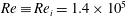 $Re\equiv Re_{i}=1.4\times 10^{5}$
–
$Re\equiv Re_{i}=1.4\times 10^{5}$
–
 $2.4\times 10^{5}$
; see figure 9).
$2.4\times 10^{5}$
; see figure 9).

Figure 11. (a) Images with front lighting showing the formation of a dual-cavity structure when a
 $D_{0}=25$
mm tungsten carbide sphere impacts at
$D_{0}=25$
mm tungsten carbide sphere impacts at
 $U_{0}=4.2$
 $\text{m}~\text{s}^{-1}$
. Here,
$\text{m}~\text{s}^{-1}$
. Here,
 $Fr=144$
. (b) Close-up images of the contact region for
$Fr=144$
. (b) Close-up images of the contact region for
 $t=5$
–
$t=5$
–
 $14$
ms from impact showing the contact line shedding event and the pacification of the K–H billows thereafter. (c) Edge enhancement of the cavity interface for
$14$
ms from impact showing the contact line shedding event and the pacification of the K–H billows thereafter. (c) Edge enhancement of the cavity interface for
 $t=5$
–
$t=5$
–
 $26$
ms. The contact line is indicated by the black arrow. The dashed curve represents the surface of the sphere.
$26$
ms. The contact line is indicated by the black arrow. The dashed curve represents the surface of the sphere.

Figure 12. Unstable, stable and helical cavity wake regimes in the
 $Fr$
–
$Fr$
–
 $Re_{0}$
parameter space for (a) steel and (b) tungsten carbide spheres. Here,
$Re_{0}$
parameter space for (a) steel and (b) tungsten carbide spheres. Here,
 $D_{0}=10$
–
$D_{0}=10$
–
 $40$
mm,
$40$
mm,
 $Re_{0}=2.7\times 10^{4}$
–
$Re_{0}=2.7\times 10^{4}$
–
 $2.6\times 10^{5}$
,
$2.6\times 10^{5}$
,
 $Fr=33.3$
–400. The dual-coloured symbols represent a bistability where two different cavity wake types can coexist separately for the same impact parameters.
$Fr=33.3$
–400. The dual-coloured symbols represent a bistability where two different cavity wake types can coexist separately for the same impact parameters.
Similarly to figure 10, close-up images with front lighting showing the formation of a dual-cavity structure are presented in figure 11. The images in (a) have been magnified further near the contact region in (b) and, additionally, enhanced using an edge-detection MATLAB routine in (c). The contact line noted around the equator at
 $t=5$
ms in this case (see the black arrow in c) is shed backwards as the sphere descends further down with time, discontinuing the local nucleate boiling. Since the elongated contact areas associated with the primary contact line are also shed in the process, the formation of liquid columns also stops, and these later appear as falling streams inside the cavity (see figure 11(a),
$t=5$
ms in this case (see the black arrow in c) is shed backwards as the sphere descends further down with time, discontinuing the local nucleate boiling. Since the elongated contact areas associated with the primary contact line are also shed in the process, the formation of liquid columns also stops, and these later appear as falling streams inside the cavity (see figure 11(a),
 $t=14$
ms). The images in (b) and (c) reveal the K–H billows forming at the vapour layer interface to pacify with time until a smooth liquid–vapour interface is observed at
$t=14$
ms). The images in (b) and (c) reveal the K–H billows forming at the vapour layer interface to pacify with time until a smooth liquid–vapour interface is observed at
 $t=26$
ms. Since the contact line is shed much earlier at
$t=26$
ms. Since the contact line is shed much earlier at
 $t=6$
ms, when the billows are still very obvious, it appears that this phenomenon results due to the contact line shedding event, rather than vice versa.
$t=6$
ms, when the billows are still very obvious, it appears that this phenomenon results due to the contact line shedding event, rather than vice versa.
3.2.3 Instability in stratified shear flows
Studies on the instability of stratified shear layers can be traced back to the works of Goldstein (Reference Goldstein1931) and Taylor (Reference Taylor1931), who analytically investigated unbounded parallel inviscid shear flows. Taylor (Reference Taylor1931) conjectured that a stable flow in such circumstances requires the gradient Richardson number
 $Ri_{g}=N_{L}^{2}/(\unicode[STIX]{x2202}u/\unicode[STIX]{x2202}z)^{2}$
(where
$Ri_{g}=N_{L}^{2}/(\unicode[STIX]{x2202}u/\unicode[STIX]{x2202}z)^{2}$
(where
 $N_{L}$
is the Brunt–Väisälä frequency and
$N_{L}$
is the Brunt–Väisälä frequency and
 $\unicode[STIX]{x2202}u/\unicode[STIX]{x2202}z$
is the local shear) to exceed a value of 0.25 everywhere. This was proved in a theorem by Miles (Reference Miles1961), whereby the velocity and density were assumed to follow monotonic profiles. Howard (Reference Howard1961) simplified Miles’s theorem such that it did not require such hypotheses, which has come to be known as the classical Miles–Howard theorem. Shear flows in reality, however, are not only bounded but can also be influenced by viscous stresses, such that the minimum critical
$\unicode[STIX]{x2202}u/\unicode[STIX]{x2202}z$
is the local shear) to exceed a value of 0.25 everywhere. This was proved in a theorem by Miles (Reference Miles1961), whereby the velocity and density were assumed to follow monotonic profiles. Howard (Reference Howard1961) simplified Miles’s theorem such that it did not require such hypotheses, which has come to be known as the classical Miles–Howard theorem. Shear flows in reality, however, are not only bounded but can also be influenced by viscous stresses, such that the minimum critical
 $Ri_{g}$
required for instability can vary significantly. A plethora of studies have investigated stratified shear flow in this regard, which can be found in the extensive reviews of Fernando (Reference Fernando1991) and Peltier & Caulfield (Reference Peltier and Caulfield2003).
$Ri_{g}$
required for instability can vary significantly. A plethora of studies have investigated stratified shear flow in this regard, which can be found in the extensive reviews of Fernando (Reference Fernando1991) and Peltier & Caulfield (Reference Peltier and Caulfield2003).
A notable work among these studies by Strang & Fernando (Reference Strang and Fernando2001) investigated the entrainment and mixing in a stratified shear layer, separating an upper lighter layer (of thickness
 $D$
) from a deep lower layer of homogeneous nature (two-layer case). For large Reynolds numbers (
$D$
) from a deep lower layer of homogeneous nature (two-layer case). For large Reynolds numbers (
 $Re\sim 10^{4}$
), the flow was shown to be governed primarily by the bulk Richardson number
$Re\sim 10^{4}$
), the flow was shown to be governed primarily by the bulk Richardson number
 $Ri_{B}=\unicode[STIX]{x0394}bD/\unicode[STIX]{x0394}U^{2}$
(a parameter related to the average gradient Richardson number
$Ri_{B}=\unicode[STIX]{x0394}bD/\unicode[STIX]{x0394}U^{2}$
(a parameter related to the average gradient Richardson number
 $\overline{Ri_{g}}$
, where
$\overline{Ri_{g}}$
, where
 $\unicode[STIX]{x0394}U$
is the velocity difference and
$\unicode[STIX]{x0394}U$
is the velocity difference and
 $\unicode[STIX]{x0394}b=g\unicode[STIX]{x0394}\unicode[STIX]{x1D70C}/\unicode[STIX]{x1D70C}_{0}$
, with
$\unicode[STIX]{x0394}b=g\unicode[STIX]{x0394}\unicode[STIX]{x1D70C}/\unicode[STIX]{x1D70C}_{0}$
, with
 $\unicode[STIX]{x1D70C}_{0}$
as the density of the upper layer, is the buoyancy jump across the shearing interface). Kelvin–Helmholtz instabilities were noted to occur predominantly for
$\unicode[STIX]{x1D70C}_{0}$
as the density of the upper layer, is the buoyancy jump across the shearing interface). Kelvin–Helmholtz instabilities were noted to occur predominantly for
 $Ri_{B}<3.2$
(
$Ri_{B}<3.2$
(
 $\overline{Ri_{g}}<0.39$
) and subsided completely for
$\overline{Ri_{g}}<0.39$
) and subsided completely for
 $Ri_{B}\gtrsim 5$
(
$Ri_{B}\gtrsim 5$
(
 $\overline{Ri_{g}}\gtrsim 1$
). For
$\overline{Ri_{g}}\gtrsim 1$
). For
 $Ri_{B}<1.5$
(
$Ri_{B}<1.5$
(
 $\overline{Ri_{g}}<0.09$
), the entrainment rate was found to be independent of
$\overline{Ri_{g}}<0.09$
), the entrainment rate was found to be independent of
 $Ri_{B}$
(or
$Ri_{B}$
(or
 $\overline{Ri_{g}}$
), indicating entrainment to occur as if stratification did not exist. Turbulent eddies in the shear layer were strong enough in these cases to scour the denser liquid against buoyancy forces. Furthermore, the turbulence properties in the mixed layer, such as the integral length scales and root mean square (r.m.s.) of velocity fluctuations, were found to be dependent on
$\overline{Ri_{g}}$
), indicating entrainment to occur as if stratification did not exist. Turbulent eddies in the shear layer were strong enough in these cases to scour the denser liquid against buoyancy forces. Furthermore, the turbulence properties in the mixed layer, such as the integral length scales and root mean square (r.m.s.) of velocity fluctuations, were found to be dependent on
 $\unicode[STIX]{x0394}U$
and
$\unicode[STIX]{x0394}U$
and
 $D$
, whereby the upper part of the layer was maintained in a turbulent state by wall-induced turbulence.
$D$
, whereby the upper part of the layer was maintained in a turbulent state by wall-induced turbulence.
The stratified turbulent shear flow problem in this study is analogous to the two-layer case investigated by Strang & Fernando (Reference Strang and Fernando2001) in the sense that the vapour layer (of thickness
 $\unicode[STIX]{x1D6FF}_{l}$
) and the PP1 fluid form the upper and lower parts of the mixed layer respectively in a rotated view frame about the sphere equator. Since the bulk Richardson number at the vapour–liquid interface in the initial stages of sphere descent (
$\unicode[STIX]{x1D6FF}_{l}$
) and the PP1 fluid form the upper and lower parts of the mixed layer respectively in a rotated view frame about the sphere equator. Since the bulk Richardson number at the vapour–liquid interface in the initial stages of sphere descent (
 $t=5$
–
$t=5$
–
 $6$
ms in figure 11,
$6$
ms in figure 11,
 $Re_{i}\sim 8\times 10^{4}$
) follows
$Re_{i}\sim 8\times 10^{4}$
) follows
 $Ri_{B}=\unicode[STIX]{x0394}b\unicode[STIX]{x1D6FF}_{l}/\unicode[STIX]{x0394}U^{2}\sim O(0.01)$
(where
$Ri_{B}=\unicode[STIX]{x0394}b\unicode[STIX]{x1D6FF}_{l}/\unicode[STIX]{x0394}U^{2}\sim O(0.01)$
(where
 $\unicode[STIX]{x1D6FF}_{l}\approx 100$
–
$\unicode[STIX]{x1D6FF}_{l}\approx 100$
–
 $200~\unicode[STIX]{x03BC}\text{m}$
at the sphere equator from Vakarelski et al. (Reference Vakarelski, Marston, Chan and Thoroddsen2011)), inadequate entrainment in the vapour layer itself is not expected to cause the contact line to shed backwards. It therefore appears that the thickness of the vapour layer
$200~\unicode[STIX]{x03BC}\text{m}$
at the sphere equator from Vakarelski et al. (Reference Vakarelski, Marston, Chan and Thoroddsen2011)), inadequate entrainment in the vapour layer itself is not expected to cause the contact line to shed backwards. It therefore appears that the thickness of the vapour layer
 $\unicode[STIX]{x1D6FF}_{l}$
formed after a time scale of one diameter penetration in the present case, i.e.
$\unicode[STIX]{x1D6FF}_{l}$
formed after a time scale of one diameter penetration in the present case, i.e.
 $tU_{0}/D_{0}=1$
, becomes sufficiently large to prevent the entrained liquid in the mixed layer from maintaining contact with the sphere surface. In other words,
$tU_{0}/D_{0}=1$
, becomes sufficiently large to prevent the entrained liquid in the mixed layer from maintaining contact with the sphere surface. In other words,
 $\unicode[STIX]{x1D6FF}_{l}<\unicode[STIX]{x1D6FF}_{m}$
at the equator for
$\unicode[STIX]{x1D6FF}_{l}<\unicode[STIX]{x1D6FF}_{m}$
at the equator for
 $t\leqslant 5$
ms, where
$t\leqslant 5$
ms, where
 $\unicode[STIX]{x1D6FF}_{m}$
corresponds to the mixed-layer thickness at the vapour–liquid interface. As
$\unicode[STIX]{x1D6FF}_{m}$
corresponds to the mixed-layer thickness at the vapour–liquid interface. As
 $\unicode[STIX]{x1D6FF}_{l}$
is primarily dependent on the sphere temperature, velocity and inertial flow forces, it is understandable why the dual-cavity observations made by Marston et al. (Reference Marston, Vakarelski and Thoroddsen2012) were reported to be a sensitive function of
$\unicode[STIX]{x1D6FF}_{l}$
is primarily dependent on the sphere temperature, velocity and inertial flow forces, it is understandable why the dual-cavity observations made by Marston et al. (Reference Marston, Vakarelski and Thoroddsen2012) were reported to be a sensitive function of
 $T_{s}$
and
$T_{s}$
and
 $U_{0}$
for a given sphere size.
$U_{0}$
for a given sphere size.
4 Quantitative results
Figure 12 summarizes the observation of stable, unstable and helical cavity wakes in the
 $Fr$
–
$Fr$
–
 $Re_{0}$
parameter space for (a) steel and (b) tungsten carbide spheres. The plots reveal stable–streamlined cavities to generally occur for
$Re_{0}$
parameter space for (a) steel and (b) tungsten carbide spheres. The plots reveal stable–streamlined cavities to generally occur for
 $Fr\gtrsim 120$
when
$Fr\gtrsim 120$
when
 $Re_{0}\lesssim 1.4\times 10^{5}$
, while helical cavity wakes are noted to form at higher Reynolds numbers, irrespective of the impact Froude values. The fact that these helical cavities share a noticeable
$Re_{0}\lesssim 1.4\times 10^{5}$
, while helical cavity wakes are noted to form at higher Reynolds numbers, irrespective of the impact Froude values. The fact that these helical cavities share a noticeable
 $Fr$
–
$Fr$
–
 $Re_{0}$
parameter space with both unstable and stable cavities for a steady Leidenfrost sphere temperature indicates that the vapour layer thickness
$Re_{0}$
parameter space with both unstable and stable cavities for a steady Leidenfrost sphere temperature indicates that the vapour layer thickness
 $\unicode[STIX]{x1D6FF}_{l}$
is a sensitive feature of not only the sphere velocity and inertial flow forces (characterized by the impact Reynolds number) but also the surface condition of the sphere upon impact. Even though all spheres employed in this study were cleaned and handled carefully, the slightest impurity contracted from the liquid free surface upon initial entry and oxidation of the sphere surface from heating can disrupt the heat transfer mechanism required to form an adequately thick vapour layer in the higher
$\unicode[STIX]{x1D6FF}_{l}$
is a sensitive feature of not only the sphere velocity and inertial flow forces (characterized by the impact Reynolds number) but also the surface condition of the sphere upon impact. Even though all spheres employed in this study were cleaned and handled carefully, the slightest impurity contracted from the liquid free surface upon initial entry and oxidation of the sphere surface from heating can disrupt the heat transfer mechanism required to form an adequately thick vapour layer in the higher
 $Re_{0}\gtrsim 1.4\times 10^{5}$
regime. This most likely explains the coexistence of disparate cavity wake states in the presence of indistinguishable flow conditions.
$Re_{0}\gtrsim 1.4\times 10^{5}$
regime. This most likely explains the coexistence of disparate cavity wake states in the presence of indistinguishable flow conditions.

Figure 13. (a,b) Vertical distance
 $z$
from the free surface, (c,d) descent velocity
$z$
from the free surface, (c,d) descent velocity
 $\text{d}z/\text{d}t$
and (e,f) acceleration
$\text{d}z/\text{d}t$
and (e,f) acceleration
 $\text{d}^{2}z/\text{d}t^{2}$
versus time
$\text{d}^{2}z/\text{d}t^{2}$
versus time
 $t$
from impact of
$t$
from impact of
 $D_{0}=$
15 mm steel spheres in unstable and stable cavity wake cases respectively; (a,c,e)
$D_{0}=$
15 mm steel spheres in unstable and stable cavity wake cases respectively; (a,c,e)
 $U_{0}=2.21$
–
$U_{0}=2.21$
–
 $2.80~\text{m}~\text{s}^{-1}$
,
$2.80~\text{m}~\text{s}^{-1}$
,
 $Fr=67{-}107$
; (b,d,f)
$Fr=67{-}107$
; (b,d,f)
 $U_{0}=2.97$
–
$U_{0}=2.97$
–
 $4.43~\text{m}~\text{s}^{-1}$
,
$4.43~\text{m}~\text{s}^{-1}$
,
 $Fr=120{-}267$
. The vertical dashed lines here and in all figures presented hereafter indicate time points when the cavity detaches from the sphere. The inset in (b) provides a magnified view of the area inside the rectangle.
$Fr=120{-}267$
. The vertical dashed lines here and in all figures presented hereafter indicate time points when the cavity detaches from the sphere. The inset in (b) provides a magnified view of the area inside the rectangle.

Figure 14. (a–c) Vertical distance
 $z$
from the free surface, (d–f) descent velocity
$z$
from the free surface, (d–f) descent velocity
 $\text{d}z/\text{d}t$
and (g–i) acceleration
$\text{d}z/\text{d}t$
and (g–i) acceleration
 $\text{d}^{2}z/\text{d}t^{2}$
versus time
$\text{d}^{2}z/\text{d}t^{2}$
versus time
 $t$
from impact of
$t$
from impact of
 $D_{0}=$
25 mm tungsten carbide spheres in unstable, stable and helical cavity wake cases respectively; (a,d,g)
$D_{0}=$
25 mm tungsten carbide spheres in unstable, stable and helical cavity wake cases respectively; (a,d,g)
 $U_{0}=3.43$
–
$U_{0}=3.43$
–
 $3.70~\text{m}~\text{s}^{-1}$
,
$3.70~\text{m}~\text{s}^{-1}$
,
 $Fr=96$
–112; (b,e,h)
$Fr=96$
–112; (b,e,h)
 $U_{0}=3.96$
–
$U_{0}=3.96$
–
 $4.43~\text{m}~\text{s}^{-1}$
,
$4.43~\text{m}~\text{s}^{-1}$
,
 $Fr=128$
–160; (c,f,i)
$Fr=128$
–160; (c,f,i)
 $U_{0}=3.96$
–
$U_{0}=3.96$
–
 $4.43~\text{m}~\text{s}^{-1}$
,
$4.43~\text{m}~\text{s}^{-1}$
,
 $Fr=128{-}160$
.
$Fr=128{-}160$
.
4.1 Sphere trajectory, velocity and acceleration
Figures 13 and 14 plot data for the vertical descent trajectory z, velocity
 $\text{d}z/\text{d}t$
and acceleration
$\text{d}z/\text{d}t$
and acceleration
 $\text{d}^{2}z/\text{d}t^{2}$
versus the time from impact for
$\text{d}^{2}z/\text{d}t^{2}$
versus the time from impact for
 $D_{0}=15$
mm steel and
$D_{0}=15$
mm steel and
 $D_{0}=25$
mm tungsten carbide spheres respectively in the case of unstable, stable and helical cavity wakes (see legends). The trajectory of the spheres is obtained using the DLTdv5 application (Hedrick Reference Hedrick2008) in MATLAB to perform a two-dimensional cross-correlation tracking on subsections of the sequential video frames comprising the lower hemisphere of the sphere. Use of the lower half of the sphere as the tracking template ensures that the cavity is not accounted for and hence does not affect the accuracy of the cross-correlation routine. Determination of the vertical position of the spheres from the full-view images in this manner is found to result in a sub-pixel position accuracy of
$D_{0}=25$
mm tungsten carbide spheres respectively in the case of unstable, stable and helical cavity wakes (see legends). The trajectory of the spheres is obtained using the DLTdv5 application (Hedrick Reference Hedrick2008) in MATLAB to perform a two-dimensional cross-correlation tracking on subsections of the sequential video frames comprising the lower hemisphere of the sphere. Use of the lower half of the sphere as the tracking template ensures that the cavity is not accounted for and hence does not affect the accuracy of the cross-correlation routine. Determination of the vertical position of the spheres from the full-view images in this manner is found to result in a sub-pixel position accuracy of
 $\pm 0.1$
pixels, corresponding to a maximum error of
$\pm 0.1$
pixels, corresponding to a maximum error of
 $\pm 0.14$
mm. Plots for the vertical velocity and acceleration are obtained by fitting the z(t) position data with a quintic smoothing spline (de Boor Reference de Boor1978; Epps, Truscott & Techet Reference Epps, Truscott and Techet2010) and computing its first and second derivatives respectively. Utilization of the spline method in this regard is important, as taking multiple derivatives of the measured data by means of finite differences (i.e
$\pm 0.14$
mm. Plots for the vertical velocity and acceleration are obtained by fitting the z(t) position data with a quintic smoothing spline (de Boor Reference de Boor1978; Epps, Truscott & Techet Reference Epps, Truscott and Techet2010) and computing its first and second derivatives respectively. Utilization of the spline method in this regard is important, as taking multiple derivatives of the measured data by means of finite differences (i.e
 $U(t)=\unicode[STIX]{x0394}z/\unicode[STIX]{x0394}t$
) amplifies the measurement error considerably. The smoothing parameter for each spline fit is chosen based on the method developed by Epps et al. (Reference Epps, Truscott and Techet2010), which is also described comprehensively in the work of Truscott et al. (Reference Truscott, Epps and Techet2012). The approach systematically determines an error tolerance of the fit (to the position data) that minimizes the roughness (data passing through all experimental points) of the fit. The advantage is that the function it produces is differentiable but also the best fit, which conserves many of the subtle yet important dynamics often removed by more common polynomial approaches.
$U(t)=\unicode[STIX]{x0394}z/\unicode[STIX]{x0394}t$
) amplifies the measurement error considerably. The smoothing parameter for each spline fit is chosen based on the method developed by Epps et al. (Reference Epps, Truscott and Techet2010), which is also described comprehensively in the work of Truscott et al. (Reference Truscott, Epps and Techet2012). The approach systematically determines an error tolerance of the fit (to the position data) that minimizes the roughness (data passing through all experimental points) of the fit. The advantage is that the function it produces is differentiable but also the best fit, which conserves many of the subtle yet important dynamics often removed by more common polynomial approaches.
Examination of the plots for the
 $D_{0}=15$
mm steel sphere in figure 13 reveals that all stable cavity wake configurations eventually reach a terminal descent velocity (
$D_{0}=15$
mm steel sphere in figure 13 reveals that all stable cavity wake configurations eventually reach a terminal descent velocity (
 $U_{t}=1.23~\text{m}~\text{s}^{-1}$
, see d). As expected, the corresponding
$U_{t}=1.23~\text{m}~\text{s}^{-1}$
, see d). As expected, the corresponding
 $\text{d}^{2}z/\text{d}t^{2}$
data in (f) show the deceleration of the spheres to decease with time, until it becomes
$\text{d}^{2}z/\text{d}t^{2}$
data in (f) show the deceleration of the spheres to decease with time, until it becomes
 $0~\text{m}~\text{s}^{-2}$
when terminal velocity is reached. The cavities in these cases remain attached to the sphere over the entire descent. For unstable cavity wake cases, the declining descent velocities reach a minimum and begin to increase as soon as the cavity shedding process is complete (see the dashed lines with markers in c). These accordingly correspond to time points in (e) whereby the spheres start accelerating during their descent. If a long enough column tank were used, these spheres would also eventually reach a terminal velocity, as shown by Vakarelski et al. (Reference Vakarelski, Marston, Chan and Thoroddsen2011). The increase in sphere velocity noted here upon cavity detachment is attributed to the reduction in buoyancy forces and also to the delayed flow separation at the sphere surface (signified by an increase in the separation angle
$0~\text{m}~\text{s}^{-2}$
when terminal velocity is reached. The cavities in these cases remain attached to the sphere over the entire descent. For unstable cavity wake cases, the declining descent velocities reach a minimum and begin to increase as soon as the cavity shedding process is complete (see the dashed lines with markers in c). These accordingly correspond to time points in (e) whereby the spheres start accelerating during their descent. If a long enough column tank were used, these spheres would also eventually reach a terminal velocity, as shown by Vakarelski et al. (Reference Vakarelski, Marston, Chan and Thoroddsen2011). The increase in sphere velocity noted here upon cavity detachment is attributed to the reduction in buoyancy forces and also to the delayed flow separation at the sphere surface (signified by an increase in the separation angle
 $\unicode[STIX]{x1D703}$
), resulting in a lower pressure-induced form drag (Vakarelski et al.
Reference Vakarelski, Marston, Chan and Thoroddsen2011). Furthermore, the cavity detachment event itself in these single trials occurs at an earlier time from impact as the impact velocity of the sphere is increased.
$\unicode[STIX]{x1D703}$
), resulting in a lower pressure-induced form drag (Vakarelski et al.
Reference Vakarelski, Marston, Chan and Thoroddsen2011). Furthermore, the cavity detachment event itself in these single trials occurs at an earlier time from impact as the impact velocity of the sphere is increased.
Unstable cavities produced using the larger and denser
 $D_{0}=25$
mm tungsten carbide spheres in figure 14 show a contrasting trend whereby cavity detachments take place earlier for reducing
$D_{0}=25$
mm tungsten carbide spheres in figure 14 show a contrasting trend whereby cavity detachments take place earlier for reducing
 $U_{0}$
values. Ideally, an increase in sphere momentum, resulting in the entrainment of a larger cavity volume (Aristoff et al.
Reference Aristoff, Truscott, Techet and Bush2010), accordingly requires a longer time for the shedding process to complete. However, since the unstable cavities here and in figure 13 originate from dual-cavity structures, whereby the pinch-off location determining the cavity volume entrained in turn varies unsystematically, the trends in cavity detachment times with respect to increasing Froude number are merely a coincidental occurrence. This was further confirmed by results from repeated trials, which indicated no particular order in detachment times for cavities initiating from dual-cavity structures.
$U_{0}$
values. Ideally, an increase in sphere momentum, resulting in the entrainment of a larger cavity volume (Aristoff et al.
Reference Aristoff, Truscott, Techet and Bush2010), accordingly requires a longer time for the shedding process to complete. However, since the unstable cavities here and in figure 13 originate from dual-cavity structures, whereby the pinch-off location determining the cavity volume entrained in turn varies unsystematically, the trends in cavity detachment times with respect to increasing Froude number are merely a coincidental occurrence. This was further confirmed by results from repeated trials, which indicated no particular order in detachment times for cavities initiating from dual-cavity structures.
Similar to the stable cavity cases in figure 13, the plots for
 $\text{d}z/\text{d}t$
and
$\text{d}z/\text{d}t$
and
 $\text{d}^{2}z/\text{d}t^{2}$
in figures 14(e) and 14(h) respectively show the denser tungsten carbide spheres in the limited fluid column length available to also be approaching a terminal velocity, with the associated deceleration values nearing
$\text{d}^{2}z/\text{d}t^{2}$
in figures 14(e) and 14(h) respectively show the denser tungsten carbide spheres in the limited fluid column length available to also be approaching a terminal velocity, with the associated deceleration values nearing
 $0~\text{m}~\text{s}^{-2}$
. Strikingly different trends are noted in the results obtained for helical in comparison to stable cavity wakes formed in an identical
$0~\text{m}~\text{s}^{-2}$
. Strikingly different trends are noted in the results obtained for helical in comparison to stable cavity wakes formed in an identical
 $Fr$
–
$Fr$
–
 $Re_{0}$
parameter space. The descent velocities in these cases (f) give the impression of following an inverted profile in relation to those observed for stable wakes in (e). In contrast to the trend in (h), these correspond to gradually increasing sphere decelerations which plateau to steady values with time (i). Decelerations during the initial stages of descent (
$Re_{0}$
parameter space. The descent velocities in these cases (f) give the impression of following an inverted profile in relation to those observed for stable wakes in (e). In contrast to the trend in (h), these correspond to gradually increasing sphere decelerations which plateau to steady values with time (i). Decelerations during the initial stages of descent (
 $t\leqslant 65$
ms), more importantly, are noted to be smaller by up to an order of magnitude in comparison with those for stable cases, indicating significantly lower hydrodynamic forces to be present in the case of helical cavity wakes.
$t\leqslant 65$
ms), more importantly, are noted to be smaller by up to an order of magnitude in comparison with those for stable cases, indicating significantly lower hydrodynamic forces to be present in the case of helical cavity wakes.
4.2 Force coefficients
The total hydrodynamic force
 $F$
acting on the sphere during its descent can be computed from the
$F$
acting on the sphere during its descent can be computed from the
 $\text{d}^{2}z/\text{d}t^{2}$
acceleration data obtained in the preceding section. This force, conventionally modelled as the sum of buoyancy
$\text{d}^{2}z/\text{d}t^{2}$
acceleration data obtained in the preceding section. This force, conventionally modelled as the sum of buoyancy
 $F_{b}$
, added mass
$F_{b}$
, added mass
 $F_{a}$
and drag
$F_{a}$
and drag
 $F_{d}$
forces, counteracts the weight and inertia of the sphere following impact to result in a net upward force and, accordingly, a downward deceleration. On performing a vertical force balance on the sphere we obtain
$F_{d}$
forces, counteracts the weight and inertia of the sphere following impact to result in a net upward force and, accordingly, a downward deceleration. On performing a vertical force balance on the sphere we obtain
 $$\begin{eqnarray}m_{s}\ddot{z}(t)=m_{s}g-F(t),\end{eqnarray}$$
where
 $m_{s}=V\unicode[STIX]{x1D70C}_{s}=(4/3)\unicode[STIX]{x03C0}R_{0}^{3}\unicode[STIX]{x1D70C}_{s}$
is the sphere mass. Using the
$m_{s}=V\unicode[STIX]{x1D70C}_{s}=(4/3)\unicode[STIX]{x03C0}R_{0}^{3}\unicode[STIX]{x1D70C}_{s}$
is the sphere mass. Using the
 $\text{d}z/\text{d}t$
velocity data, the total hydrodynamic force coefficient can then be calculated using
$\text{d}z/\text{d}t$
velocity data, the total hydrodynamic force coefficient can then be calculated using
 $$\begin{eqnarray}C_{F}(t)={\displaystyle \frac{F(t)}{\frac{1}{2}\unicode[STIX]{x1D70C}[{\dot{z}}(t)^{2}]\unicode[STIX]{x03C0}R_{0}^{2}}}={\displaystyle \frac{m_{s}[g-\ddot{z}(t)]}{\frac{1}{2}\unicode[STIX]{x1D70C}[{\dot{z}}(t)^{2}]\unicode[STIX]{x03C0}R_{0}^{2}}}.\end{eqnarray}$$
Figure 15 plots the hydrodynamic force coefficients for the stable, unstable and helical cavity wake cases produced using steel and tungsten carbide sphere impacts in figures 13 and 14 respectively. Plots for the unstable (a,c) relative to stable (b,d) wake cases reveal the force coefficients to increase more steeply with time and reach higher maxima, which then begin to incur sharp declines moments before (
 ${\approx}40$
ms) the cavity shedding process is observed to be complete (see dashed lines). These declines are noted to be even more precipitous for the denser tungsten carbide sphere in (c). The force coefficients for the stable wake cases, in contrast, approach a steady value with time (e.g.
${\approx}40$
ms) the cavity shedding process is observed to be complete (see dashed lines). These declines are noted to be even more precipitous for the denser tungsten carbide sphere in (c). The force coefficients for the stable wake cases, in contrast, approach a steady value with time (e.g.
 $C_{F}\approx 0.6$
in b), which is expected by definition of
$C_{F}\approx 0.6$
in b), which is expected by definition of
 $C_{F}$
(4.2) as the sphere reaches a terminal descent velocity. The
$C_{F}$
(4.2) as the sphere reaches a terminal descent velocity. The
 $C_{F}$
values, increasing steadily with time for helical cavity wakes, are noted to be significantly smaller (by 40 %–55 %) than those obtained for their stable wake counterparts at the same impact parameters.
$C_{F}$
values, increasing steadily with time for helical cavity wakes, are noted to be significantly smaller (by 40 %–55 %) than those obtained for their stable wake counterparts at the same impact parameters.
The dramatic reduction in force coefficients observed for helical wake cases can be reasoned to be due to the combined effect of an increase in cone angle
 $\unicode[STIX]{x1D703}_{c}$
, defined as the angle of the cavity interface with respect to the vertical tangent at the sphere equator (Aristoff & Bush Reference Aristoff and Bush2009), and the nature of flow structures produced around the descending sphere. While the cone angles for stable–streamlined cavity wakes follow constant values ranging between
$\unicode[STIX]{x1D703}_{c}$
, defined as the angle of the cavity interface with respect to the vertical tangent at the sphere equator (Aristoff & Bush Reference Aristoff and Bush2009), and the nature of flow structures produced around the descending sphere. While the cone angles for stable–streamlined cavity wakes follow constant values ranging between
 $\unicode[STIX]{x1D703}_{c}=165^{\circ }$
and
$\unicode[STIX]{x1D703}_{c}=165^{\circ }$
and
 $168^{\circ }$
, which are in close agreement with
$168^{\circ }$
, which are in close agreement with
 $\unicode[STIX]{x1D703}_{c}\backsim 165^{\circ }$
reported by Marston et al. (Reference Marston, Vakarelski and Thoroddsen2012) for Leidenfrost sphere cavities formed immediately after impact (
$\unicode[STIX]{x1D703}_{c}\backsim 165^{\circ }$
reported by Marston et al. (Reference Marston, Vakarelski and Thoroddsen2012) for Leidenfrost sphere cavities formed immediately after impact (
 $t=6.5$
ms), the angles for the asymmetric helical cavity wakes take higher and unsteady circumferential values in the range of
$t=6.5$
ms), the angles for the asymmetric helical cavity wakes take higher and unsteady circumferential values in the range of
 $\unicode[STIX]{x1D703}_{c}=172^{\circ }$
–
$\unicode[STIX]{x1D703}_{c}=172^{\circ }$
–
 $179^{\circ }$
. As larger cone angles imply smaller frontal areas, which result in a decrease in the amount of fluid forced radially outwards and, accordingly, the momentum imparted to the liquid by the descending sphere, a reduction in
$179^{\circ }$
. As larger cone angles imply smaller frontal areas, which result in a decrease in the amount of fluid forced radially outwards and, accordingly, the momentum imparted to the liquid by the descending sphere, a reduction in
 $C_{F}$
values is understandable in the helical wake cases. Additionally, since the formation and rotation of ridges at the contact line in these helical wakes is suspected to be a by-product of large-scale vortex shedding occurring at distinct points rotating around the sphere periodically (Achenbach Reference Achenbach1974), the fluid in the vicinity of the contact line can also be expected to experience an azimuthal rotation. This phenomenon whereby the sphere descends with a corkscrew or spiralling effect on the flow can play a major role in reducing the opposing hydrodynamic forces and, hence, the
$C_{F}$
values is understandable in the helical wake cases. Additionally, since the formation and rotation of ridges at the contact line in these helical wakes is suspected to be a by-product of large-scale vortex shedding occurring at distinct points rotating around the sphere periodically (Achenbach Reference Achenbach1974), the fluid in the vicinity of the contact line can also be expected to experience an azimuthal rotation. This phenomenon whereby the sphere descends with a corkscrew or spiralling effect on the flow can play a major role in reducing the opposing hydrodynamic forces and, hence, the
 $C_{F}$
values obtained. Further experiments utilizing PIV techniques are recommended in the future to study and confirm the presence of such flow structures.
$C_{F}$
values obtained. Further experiments utilizing PIV techniques are recommended in the future to study and confirm the presence of such flow structures.

Figure 15. Force coefficients for (a,b)
 $D_{0}=15$
mm steel and (c–e)
$D_{0}=15$
mm steel and (c–e)
 $D_{0}=25$
mm tungsten carbide spheres from the trajectory measurements in figures 13 and 14 respectively. (a,c) Unstable wake cases. (b,d) Stable wake cases. (e) Helical wake cases. Here,
$D_{0}=25$
mm tungsten carbide spheres from the trajectory measurements in figures 13 and 14 respectively. (a,c) Unstable wake cases. (b,d) Stable wake cases. (e) Helical wake cases. Here,
 $U_{0}=2.21$
–
$U_{0}=2.21$
–
 $4.43~\text{m}~\text{s}^{-1}$
,
$4.43~\text{m}~\text{s}^{-1}$
,
 $Fr=67$
–160.
$Fr=67$
–160.
4.3 Drag coefficients
4.3.1 Spline interpolation method
From the total hydrodynamic force data obtained in section (§ 4.2), the drag force
 $F_{d}$
resisting the motion of the sphere and the attached cavity wake can be obtained using
$F_{d}$
resisting the motion of the sphere and the attached cavity wake can be obtained using
 $$\begin{eqnarray}F_{d}(t)=F(t)-F_{a}(t)-F_{b}(t).\end{eqnarray}$$
The effect (force) of added mass
 $m_{a}$
from accelerating the surrounding fluid can be expressed as
$m_{a}$
from accelerating the surrounding fluid can be expressed as
 $F_{a}(t)=m_{a}\ddot{z}(t)=C_{m}V_{c}\unicode[STIX]{x1D70C}\ddot{z}(t)$
, where
$F_{a}(t)=m_{a}\ddot{z}(t)=C_{m}V_{c}\unicode[STIX]{x1D70C}\ddot{z}(t)$
, where
 $C_{m}$
is the added mass coefficient and
$C_{m}$
is the added mass coefficient and
 $V_{c}$
is the combined volume of the sphere and cavity wake. Although the magnitude of
$V_{c}$
is the combined volume of the sphere and cavity wake. Although the magnitude of
 $V_{c}$
varies with time due to cavity shedding, and
$V_{c}$
varies with time due to cavity shedding, and
 $C_{m}$
in turn depends on the flow pattern around the sphere and trailing cavity (Berklite Reference Berklite1972; Sarpkaya Reference Sarpkaya1976), a constant mean value for the added mass obtained from
$C_{m}$
in turn depends on the flow pattern around the sphere and trailing cavity (Berklite Reference Berklite1972; Sarpkaya Reference Sarpkaya1976), a constant mean value for the added mass obtained from
 $m_{a}=0.672\unicode[STIX]{x1D70C}[(1/6)\unicode[STIX]{x03C0}L_{c}D_{c}^{2}]$
for streamlined bodies (Dong Reference Dong1978) is assumed over the entire descent. The added mass for spheres falling without cavity attachments is simply given by
$m_{a}=0.672\unicode[STIX]{x1D70C}[(1/6)\unicode[STIX]{x03C0}L_{c}D_{c}^{2}]$
for streamlined bodies (Dong Reference Dong1978) is assumed over the entire descent. The added mass for spheres falling without cavity attachments is simply given by
 $m_{a}=C_{m}V\unicode[STIX]{x1D70C}$
, where
$m_{a}=C_{m}V\unicode[STIX]{x1D70C}$
, where
 $C_{m}$
takes a constant value of
$C_{m}$
takes a constant value of
 $0.5$
.
$0.5$
.
Since the cavity adjoins the sphere at or close to its equator, the total buoyancy force
 $F_{b}$
due to hydrostatic pressure before cavity pinch-off (i.e. for an open sphere–cavity system exposed to the atmosphere) is given by
$F_{b}$
due to hydrostatic pressure before cavity pinch-off (i.e. for an open sphere–cavity system exposed to the atmosphere) is given by
 $F_{b}(t)=\unicode[STIX]{x1D70C}(2/3)\unicode[STIX]{x03C0}R_{0}^{3}g+\unicode[STIX]{x1D70C}g[z(t)-R_{0}]\unicode[STIX]{x03C0}R_{0}^{2}$
. Following the pinch-off event, a closed sphere–cavity system completely surrounded by the fluid is formed whereby
$F_{b}(t)=\unicode[STIX]{x1D70C}(2/3)\unicode[STIX]{x03C0}R_{0}^{3}g+\unicode[STIX]{x1D70C}g[z(t)-R_{0}]\unicode[STIX]{x03C0}R_{0}^{2}$
. Following the pinch-off event, a closed sphere–cavity system completely surrounded by the fluid is formed whereby
 $F_{b}=\unicode[STIX]{x1D70C}V_{c}g$
. The combined volume of the sphere and the attached cavity wake
$F_{b}=\unicode[STIX]{x1D70C}V_{c}g$
. The combined volume of the sphere and the attached cavity wake
 $V_{c}$
is obtained by tracing their boundary around the vertical
$V_{c}$
is obtained by tracing their boundary around the vertical
 $Z$
-axis using spline interpolation (see figure 16
a–c), approximating it using a piecewise-linear curve to form a closed polygonal chain and, finally, revolving the polygonal chain about the
$Z$
-axis using spline interpolation (see figure 16
a–c), approximating it using a piecewise-linear curve to form a closed polygonal chain and, finally, revolving the polygonal chain about the
 $Z$
-axis of symmetry to give the volume of revolution. In mathematical terminology, if the sphere–cavity boundary curve closed around the
$Z$
-axis of symmetry to give the volume of revolution. In mathematical terminology, if the sphere–cavity boundary curve closed around the
 $Z$
-axis is parameterized as
$Z$
-axis is parameterized as
 $\langle R(s),Z(s)\rangle$
for
$\langle R(s),Z(s)\rangle$
for
 $0\leqslant s\leqslant 1$
, then the volume of revolution about the
$0\leqslant s\leqslant 1$
, then the volume of revolution about the
 $Z$
-axis can be expressed as (Wilson, Turcotte & Halpern Reference Wilson, Turcotte and Halpern2003)
$Z$
-axis can be expressed as (Wilson, Turcotte & Halpern Reference Wilson, Turcotte and Halpern2003)
 $$\begin{eqnarray}V_{c}={\displaystyle \frac{2\unicode[STIX]{x03C0}}{3}}\int _{0}^{1}R(s)[R(s)Z^{\prime }(s)-Z(s)R^{\prime }(s)]\,\text{d}s.\end{eqnarray}$$
The
 $V_{c}$
values corresponding to unstable, stable and helical cavity wake cases produced by the impact of
$V_{c}$
values corresponding to unstable, stable and helical cavity wake cases produced by the impact of
 $D_{0}=15$
mm steel and
$D_{0}=15$
mm steel and
 $D_{0}=25$
mm tungsten carbide spheres are computed using (4.4) at 20 ms time steps and plotted in figure 16(d,e); see the caption for details. Since the splines (in red) are interpolated between manually drawn boundary points (in yellow), the volume
$D_{0}=25$
mm tungsten carbide spheres are computed using (4.4) at 20 ms time steps and plotted in figure 16(d,e); see the caption for details. Since the splines (in red) are interpolated between manually drawn boundary points (in yellow), the volume
 $V_{c}$
is subjective to how the cavity shape is perceived at each time step. For example,
$V_{c}$
is subjective to how the cavity shape is perceived at each time step. For example,
 $V_{c}$
values obtained over repeated measurements for the stable–streamlined cavity of an apparently constant volume in figure 16(d) (see the bracketed area) are found to have a mean and mean absolute deviation (MAD) of
$V_{c}$
values obtained over repeated measurements for the stable–streamlined cavity of an apparently constant volume in figure 16(d) (see the bracketed area) are found to have a mean and mean absolute deviation (MAD) of
 $7.29~\text{cm}^{3}$
and
$7.29~\text{cm}^{3}$
and
 $0.12~\text{cm}^{3}$
respectively. These results are found to be in close agreement with the true volume
$0.12~\text{cm}^{3}$
respectively. These results are found to be in close agreement with the true volume
 $V_{c}=7.31~\text{cm}^{3}$
(see the methodology of computation in § 4.3.2) and have a mean absolute percentage error (MAPE) of 1.7 %. The total error in volume measurement for unstable and helical wake cases, however, is higher due to cavity asymmetry and more difficult to pin down.
$V_{c}=7.31~\text{cm}^{3}$
(see the methodology of computation in § 4.3.2) and have a mean absolute percentage error (MAPE) of 1.7 %. The total error in volume measurement for unstable and helical wake cases, however, is higher due to cavity asymmetry and more difficult to pin down.

Figure 16. Cavity interfaces traced around the vertical
 $Z$
-axis (purple line) using spline interpolation (in red) between manually drawn boundary points (in yellow) for (a) an unstable wake case,
$Z$
-axis (purple line) using spline interpolation (in red) between manually drawn boundary points (in yellow) for (a) an unstable wake case,
 $D_{0}=15$
mm,
$D_{0}=15$
mm,
 $\unicode[STIX]{x1D71A}=4.54$
,
$\unicode[STIX]{x1D71A}=4.54$
,
 $U_{0}=2.21~\text{m}~\text{s}^{-1}$
,
$U_{0}=2.21~\text{m}~\text{s}^{-1}$
,
 $Fr=67$
(b) a stable wake case,
$Fr=67$
(b) a stable wake case,
 $D_{0}=15$
mm,
$D_{0}=15$
mm,
 $\unicode[STIX]{x1D71A}=4.54$
,
$\unicode[STIX]{x1D71A}=4.54$
,
 $U_{0}=2.97~\text{m}~\text{s}^{-1}$
,
$U_{0}=2.97~\text{m}~\text{s}^{-1}$
,
 $Fr=120$
, and (c) a helical wake case,
$Fr=120$
, and (c) a helical wake case,
 $D_{0}=25$
mm,
$D_{0}=25$
mm,
 $\unicode[STIX]{x1D71A}=8.70$
,
$\unicode[STIX]{x1D71A}=8.70$
,
 $U_{0}=4.20~\text{m}~\text{s}^{-1}$
,
$U_{0}=4.20~\text{m}~\text{s}^{-1}$
,
 $Fr=144$
. (d) The total volume of the sphere and cavity
$Fr=144$
. (d) The total volume of the sphere and cavity
 $V_{c}$
versus time for the realizations in (a,b). (e) Plot of
$V_{c}$
versus time for the realizations in (a,b). (e) Plot of
 $V_{c}$
versus
$V_{c}$
versus
 $t$
for unstable and stable cavity wakes produced by the impact of
$t$
for unstable and stable cavity wakes produced by the impact of
 $D_{0}=25$
mm tungsten carbide spheres for
$D_{0}=25$
mm tungsten carbide spheres for
 $U_{0}=3.57~\text{m}~\text{s}^{-1}$
,
$U_{0}=3.57~\text{m}~\text{s}^{-1}$
,
 $Fr=104$
and
$Fr=104$
and
 $U_{0}=4.20~\text{m}~\text{s}^{-1}$
,
$U_{0}=4.20~\text{m}~\text{s}^{-1}$
,
 $Fr=144$
respectively and for the helical wake case in (c). The horizontal dashed lines correspond to times whereby the cavity has been completely shed off, i.e.
$Fr=144$
respectively and for the helical wake case in (c). The horizontal dashed lines correspond to times whereby the cavity has been completely shed off, i.e.
 $V_{c}=(4/3)\unicode[STIX]{x03C0}R_{0}^{3}$
.
$V_{c}=(4/3)\unicode[STIX]{x03C0}R_{0}^{3}$
.
From the plots shown in figure 16(d,e), the volume of air entrained by the helical wake upon pinch-off is computed to be significantly smaller (by
 ${\approx}60\,\%$
) than the stable wake counterpart for the same impact parameters. The
${\approx}60\,\%$
) than the stable wake counterpart for the same impact parameters. The
 $V_{c}$
values for unstable wake cases generally decline at the steepest rate in a stepwise manner until the sphere volume
$V_{c}$
values for unstable wake cases generally decline at the steepest rate in a stepwise manner until the sphere volume
 $V$
(see dashed line) is reached upon completion of the shedding process. The buoyancy then becomes constant and can be obtained directly from
$V$
(see dashed line) is reached upon completion of the shedding process. The buoyancy then becomes constant and can be obtained directly from
 $F_{b}=(4/3)\unicode[STIX]{x03C0}R_{0}^{3}\unicode[STIX]{x1D70C}g$
.
$F_{b}=(4/3)\unicode[STIX]{x03C0}R_{0}^{3}\unicode[STIX]{x1D70C}g$
.

Figure 17. Drag coefficients for the unstable, stable and helical cavity wake cases produced by (a)
 $D_{0}=15$
mm steel and (b)
$D_{0}=15$
mm steel and (b)
 $D_{0}=25$
mm tungsten carbide spheres in figure 16(d,e). The black filled, colour filled and unfilled symbols represent
$D_{0}=25$
mm tungsten carbide spheres in figure 16(d,e). The black filled, colour filled and unfilled symbols represent
 $C_{D}$
values before pinch-off, after pinch-off and after cavity detachment respectively.
$C_{D}$
values before pinch-off, after pinch-off and after cavity detachment respectively.
Using equations (4.1) and (4.3) together with the relevant expressions for
 $F_{a}$
and
$F_{a}$
and
 $F_{b}$
applicable before pinch-off, after pinch-off and after cavity detachment discussed above, the general equation for the drag coefficient given by
$F_{b}$
applicable before pinch-off, after pinch-off and after cavity detachment discussed above, the general equation for the drag coefficient given by
 $$\begin{eqnarray}C_{D}(t)={\displaystyle \frac{[F(t)-F_{a}(t)-F_{b}(t)]}{\frac{1}{2}\unicode[STIX]{x1D70C}[{\dot{z}}(t)^{2}]\unicode[STIX]{x03C0}R_{0}^{2}}}\end{eqnarray}$$
can be expressed for each respective phase as
 $$\begin{eqnarray}\displaystyle & \hspace{-3.60004pt}\displaystyle C_{D}(t)_{\begin{array}{@{}l@{}}\mathit{Before}\\ \mathit{pinch}\text{-}\mathit{off}\end{array}}={\displaystyle \frac{m_{s}[g-\ddot{z}(t)]-\left[0.672\unicode[STIX]{x1D70C}\left(\frac{1}{6}\unicode[STIX]{x03C0}L_{c}D_{c}^{2}\right)\right]\ddot{z}(t)-\left[\unicode[STIX]{x1D70C}\frac{2}{3}\unicode[STIX]{x03C0}R_{0}^{3}g+\unicode[STIX]{x1D70C}g[z(t)-R_{0}]\unicode[STIX]{x03C0}R_{0}^{2}\right]}{\frac{1}{2}\unicode[STIX]{x1D70C}[{\dot{z}}(t)^{2}]\unicode[STIX]{x03C0}R_{0}^{2}}},\hspace{-6.0pt} & \displaystyle \nonumber\\ \displaystyle & & \displaystyle\end{eqnarray}$$
 $$\begin{eqnarray}\displaystyle & \hspace{-3.60004pt}\displaystyle C_{D}(t)_{\begin{array}{@{}l@{}}\mathit{After}\\ \mathit{pinch}\text{-}\mathit{off}\end{array}}={\displaystyle \frac{m_{s}[g-\ddot{z}(t)]-\left[0.672\unicode[STIX]{x1D70C}\left(\frac{1}{6}\unicode[STIX]{x03C0}L_{c}D_{c}^{2}\right)\right]\ddot{z}(t)-\unicode[STIX]{x1D70C}V_{c}g}{\frac{1}{2}\unicode[STIX]{x1D70C}[{\dot{z}}(t)^{2}]\unicode[STIX]{x03C0}R_{0}^{2}}}, & \displaystyle\end{eqnarray}$$
 $$\begin{eqnarray}\displaystyle & \hspace{-3.60004pt}\displaystyle C_{D}(t)_{\begin{array}{@{}l@{}}\mathit{After~cavity}\\ \mathit{detachment}\end{array}}={\displaystyle \frac{m_{s}[g-\ddot{z}(t)]-\frac{4}{3}\unicode[STIX]{x03C0}R_{0}^{3}\unicode[STIX]{x1D70C}\left[\frac{1}{2}\ddot{z}(t)+g\right]}{\frac{1}{2}\unicode[STIX]{x1D70C}[{\dot{z}}(t)^{2}]\unicode[STIX]{x03C0}R_{0}^{2}}}. & \displaystyle\end{eqnarray}$$
Drag coefficients corresponding to the unstable, stable and helical wake cases in figure 16 are computed using (4.6)–(4.8) for any such given phase observed (see the caption for details) and plotted versus time in figure 17. The plots reveal the
 $C_{D}$
values to follow a declining trend after cavity pinch-off in the former two cases. While the drag coefficients for stable wakes appear to approach a steady value with time (e.g. mean
$C_{D}$
values to follow a declining trend after cavity pinch-off in the former two cases. While the drag coefficients for stable wakes appear to approach a steady value with time (e.g. mean
 $\overline{C_{D}}=0.051$
in (a) corresponding to the bracket in figure 16
d), the coefficients for unstable wakes begin to increase rapidly at
$\overline{C_{D}}=0.051$
in (a) corresponding to the bracket in figure 16
d), the coefficients for unstable wakes begin to increase rapidly at
 $t\approx 125$
ms until they reach a maximum. This dramatic increase stems from obtaining comparatively higher
$t\approx 125$
ms until they reach a maximum. This dramatic increase stems from obtaining comparatively higher
 $C_{F}$
values (see figure 15) and primarily from significantly lower buoyancy force coefficients
$C_{F}$
values (see figure 15) and primarily from significantly lower buoyancy force coefficients
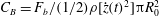 $C_{B}=F_{b}/(1/2)\unicode[STIX]{x1D70C}[{\dot{z}}(t)^{2}]\unicode[STIX]{x03C0}R_{0}^{2}$
computed for unstable wakes due to incessant cavity shedding. The effect of sharply declining
$C_{B}=F_{b}/(1/2)\unicode[STIX]{x1D70C}[{\dot{z}}(t)^{2}]\unicode[STIX]{x03C0}R_{0}^{2}$
computed for unstable wakes due to incessant cavity shedding. The effect of sharply declining
 $C_{F}$
values shortly before (
$C_{F}$
values shortly before (
 ${\approx}40$
ms) the shedding process is completed then becomes the dominating factor and accordingly causes the
${\approx}40$
ms) the shedding process is completed then becomes the dominating factor and accordingly causes the
 $C_{D}$
curves to undergo steep declines. Although the drag coefficients for the helical wake sphere increase steadily with time, the values obtained in the initial stages of descent (e.g. at
$C_{D}$
curves to undergo steep declines. Although the drag coefficients for the helical wake sphere increase steadily with time, the values obtained in the initial stages of descent (e.g. at
 $t=25$
ms, i.e. before pinch-off) are noted to be significantly smaller (by
$t=25$
ms, i.e. before pinch-off) are noted to be significantly smaller (by
 ${\approx}75\,\%$
) in comparison with those obtained for its stable wake counterpart. Given that non-cavity-forming cases tend to have even higher force coefficients than cavity-forming cases during free-surface entry (Truscott et al.
Reference Truscott, Epps and Techet2012), these results indicate helical cavity wake cases to produce an ideal configuration for the free-surface entry of spheres.
${\approx}75\,\%$
) in comparison with those obtained for its stable wake counterpart. Given that non-cavity-forming cases tend to have even higher force coefficients than cavity-forming cases during free-surface entry (Truscott et al.
Reference Truscott, Epps and Techet2012), these results indicate helical cavity wake cases to produce an ideal configuration for the free-surface entry of spheres.

Figure 18. Magnified image of a stable–streamlined cavity produced by the impact of a
 $D_{0}=10$
mm steel sphere at
$D_{0}=10$
mm steel sphere at
 $U_{0}=4.2$
 $\text{m}~\text{s}^{-1}$
,
$\text{m}~\text{s}^{-1}$
,
 $Fr=360$
. The inflow section is described by an ellipse and the outflow section by a parabola which are superimposed on the image over lengths
$Fr=360$
. The inflow section is described by an ellipse and the outflow section by a parabola which are superimposed on the image over lengths
 $L_{e}$
and
$L_{e}$
and
 $L_{r}$
respectively.
$L_{r}$
respectively.
4.3.2 Algebraic curve fitting method
Since the stable–streamlined cavity wakes formed in this study have well-defined shapes which remain consistent during sphere descent, more accurate drag coefficients for these cases can be obtained by utilizing high-magnification imaging and computing the corresponding
 $V_{c}$
volumes by characterizing their profiles using algebraic curves (to eliminate the element of manual input in boundary tracing). The sphere–cavity configuration in this regard can be modelled as a streamlined body of revolution consisting of an ellipse forebody and a parabola afterbody (Chen et al.
Reference Chen, Xia, Liu and Wang2010). The ellipse inflow section is expressed as
$V_{c}$
volumes by characterizing their profiles using algebraic curves (to eliminate the element of manual input in boundary tracing). The sphere–cavity configuration in this regard can be modelled as a streamlined body of revolution consisting of an ellipse forebody and a parabola afterbody (Chen et al.
Reference Chen, Xia, Liu and Wang2010). The ellipse inflow section is expressed as
 $$\begin{eqnarray}R=\pm {\displaystyle \frac{D_{c}}{2L_{e}}}\sqrt{L_{e}^{2}-Z^{2}}\end{eqnarray}$$
and the parabola outflow section is given by
 $$\begin{eqnarray}R=\pm {\displaystyle \frac{D_{c}}{2}}\left(1-{\displaystyle \frac{Z^{2}}{L_{r}^{2}}}\right),\end{eqnarray}$$
where
 $L_{e}$
is the inflow section length,
$L_{e}$
is the inflow section length,
 $L_{r}$
is the outflow section length (see figure 18) and
$L_{r}$
is the outflow section length (see figure 18) and
 $L_{c}=L_{e}+L_{r}$
is the total cavity length. By performing disk integration on each section over its respective length, the total volume of the stable–streamlined configuration can be given as
$L_{c}=L_{e}+L_{r}$
is the total cavity length. By performing disk integration on each section over its respective length, the total volume of the stable–streamlined configuration can be given as
 $$\begin{eqnarray}V_{c}=\unicode[STIX]{x03C0}D_{c}^{2}\left({\displaystyle \frac{L_{e}}{6}}+{\displaystyle \frac{2L_{r}}{15}}\right).\end{eqnarray}$$
Given that the spheres approach a terminal velocity
 $U_{t}$
in stable cavity wake cases, the steady-state drag coefficients can finally be obtained using
$U_{t}$
in stable cavity wake cases, the steady-state drag coefficients can finally be obtained using
 $$\begin{eqnarray}C_{D}={\displaystyle \frac{g(m_{s}-\unicode[STIX]{x1D70C}V_{c})}{\frac{1}{2}\unicode[STIX]{x1D70C}U_{t}^{2}\unicode[STIX]{x03C0}R_{c}^{2}}}.\end{eqnarray}$$
These are presented along with the corresponding Reynolds numbers
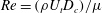 $Re=(\unicode[STIX]{x1D70C}U_{t}D_{c})/\unicode[STIX]{x1D707}$
in table 2 for different sizes of steel and tungsten carbide spheres.
$Re=(\unicode[STIX]{x1D70C}U_{t}D_{c})/\unicode[STIX]{x1D707}$
in table 2 for different sizes of steel and tungsten carbide spheres.
Table 2. Steady-state drag coefficients for stable–streamlined cavity wakes obtained using high-magnification imaging and algebraic curve fitting.

The results obtained for stable cavity wake cases produced by steel spheres range between
 $C_{D}=0.038$
and
$C_{D}=0.038$
and
 $0.043$
for
$0.043$
for
 $Re=1.9\times 10^{4}$
–
$Re=1.9\times 10^{4}$
–
 $7.1\times 10^{4}$
and those produced by tungsten carbide spheres range between
$7.1\times 10^{4}$
and those produced by tungsten carbide spheres range between
 $C_{D}=0.021$
and
$C_{D}=0.021$
and
 $0.024$
for
$0.024$
for
 $Re=3.1\times 10^{4}$
–
$Re=3.1\times 10^{4}$
–
 $8.3\times 10^{4}$
. If the sphere cross-sectional area is used to non-dimensionalize the drag coefficient for comparison purposes with results in § 4.3.1, a
$8.3\times 10^{4}$
. If the sphere cross-sectional area is used to non-dimensionalize the drag coefficient for comparison purposes with results in § 4.3.1, a
 $C_{D}$
value of 0.049 is obtained for the
$C_{D}$
value of 0.049 is obtained for the
 $D_{0}=15$
mm steel sphere stable cavity configuration. This is in agreement with the range of values and mean computed in figure 17(a) in the corresponding steady-state regime (
$D_{0}=15$
mm steel sphere stable cavity configuration. This is in agreement with the range of values and mean computed in figure 17(a) in the corresponding steady-state regime (
 $C_{D}=0.037$
–
$C_{D}=0.037$
–
 $0.065$
,
$0.065$
,
 $\overline{C_{D}}=0.051$
), which shows the
$\overline{C_{D}}=0.051$
), which shows the
 $V_{c}$
calculation procedure used therein to provide a good estimate for
$V_{c}$
calculation procedure used therein to provide a good estimate for
 $C_{D}$
values.
$C_{D}$
values.
Comparing results with past studies, the drag coefficients obtained for the streamlined cavity configuration are an order of magnitude smaller than those reported for a solid room-temperature sphere,
 $0.43<C_{D}<0.5$
(Achenbach Reference Achenbach1972), and up to
$0.43<C_{D}<0.5$
(Achenbach Reference Achenbach1972), and up to
 ${\approx}80\,\%$
smaller than the low limiting value for a simple Leidenfrost vapour layer sphere,
${\approx}80\,\%$
smaller than the low limiting value for a simple Leidenfrost vapour layer sphere,
 $C_{D}=0.1$
(Vakarelski et al.
Reference Vakarelski, Marston, Chan and Thoroddsen2011), for the same range of pre-crisis Reynolds numbers as investigated in this study. This diminution in
$C_{D}=0.1$
(Vakarelski et al.
Reference Vakarelski, Marston, Chan and Thoroddsen2011), for the same range of pre-crisis Reynolds numbers as investigated in this study. This diminution in
 $C_{D}$
is attributed to the combined effect of a reduced form drag (or pressure drag), resulting from the streamlined shape of the sphere–cavity configuration, and a lowered skin-friction drag (or viscous drag) due to the presence of a partial-slip boundary condition at the vapour layer next to the solid sphere (Vakarelski et al.
Reference Vakarelski, Berry, Chan and Thoroddsen2016). While form drag is the dominant source of drag for spheres, or more generally bluff bodies at high Reynolds numbers
$C_{D}$
is attributed to the combined effect of a reduced form drag (or pressure drag), resulting from the streamlined shape of the sphere–cavity configuration, and a lowered skin-friction drag (or viscous drag) due to the presence of a partial-slip boundary condition at the vapour layer next to the solid sphere (Vakarelski et al.
Reference Vakarelski, Berry, Chan and Thoroddsen2016). While form drag is the dominant source of drag for spheres, or more generally bluff bodies at high Reynolds numbers
 $Re=10^{4}$
–
$Re=10^{4}$
–
 $10^{6}$
, both form and skin-friction drag are expected to have a notable contribution towards the total drag experienced by streamlined bodies. Determining the precise contribution of the streamlined sphere–cavity shape and the partial-slip boundary condition in this regard towards lowering the effective drag coefficient, however, is beyond the scope of this work and will require further investigative studies in the future.
$10^{6}$
, both form and skin-friction drag are expected to have a notable contribution towards the total drag experienced by streamlined bodies. Determining the precise contribution of the streamlined sphere–cavity shape and the partial-slip boundary condition in this regard towards lowering the effective drag coefficient, however, is beyond the scope of this work and will require further investigative studies in the future.
5 Summary and conclusions
This study presents an experimental investigation on the formation of stable–streamlined and helical cavity wakes from the free-surface impact of Leidenfrost spheres. Elongated cavities entrained in the presence of wall effects are observed to pinch off at the crest of acoustic waves (or ripples) in an acoustic pinch-off cascade, which are initiated by the pressure perturbation of the deep seal event. The presence of multiple simultaneously necking regions (occurring at these crests) acts to enhance the air flow mechanism proposed by Gekle et al. (Reference Gekle, Peters, Gordillo, Van der Meer and Lohse2010) through the topmost shrinking neck region (Mansoor et al. Reference Mansoor, Marston, Vakarelski and Thoroddsen2014). This causes the cavity apex to swell up, prevent the cavity walls from colliding and, hence, suppress the formation of the downward-facing jet which can otherwise impact and distort the cavity walls. The absence of physical contact between the sphere and the liquid due to the sphere being encapsulated by a vapour layer is essential for the pacification of acoustic rippling along the cavity interface. The suppression of the downward jet can persist even after the acoustic ripples have subdued due to a skin-friction drag effect preventing collapse at the trailing cavity-wall junction. Such a series of events leads to the formation of a stable–streamlined cavity which then follows a steady descent velocity.
Kelvin–Helmholtz instabilities occurring from velocity shear are noted at the liquid–vapour interface around the bottom hemisphere of the sphere in the event of forming a sufficiently thin vapour jacket. The instability manifests in the form of several billows which can degenerate into turbulence further downstream at the sphere equator, mixing liquid into the vapour layer in the process to form an evident contact line. The presence of a spiralling instability in large-scale vortex shedding (Achenbach Reference Achenbach1974; Chomaz et al. Reference Chomaz, Bonneton and Hopfinger1993) is suspected to aggravate this mixing at distinct circumferential locations around the sphere equator in a rotating manner. This is manifested by the longitudinal enlargement of the contact region at each respective location, which in turn results in the formation of ridges along the cavity interface. The ridges follow random trajectories about the sphere equator, but once the entrained cavity collapses midway, become arranged at equidistant circumferential locations and begin rotating synchronously to form a helical cavity wake.
The helical wake configuration is found to occur for impact Reynolds numbers
 $Re_{0}\gtrsim 1.4\times 10^{5}$
and experience considerably smaller overall force coefficients (by 40 %–55 %) in comparison with those obtained for stable wake cases from sphere trajectory measurements. Furthermore, the drag coefficients in the initial stages of descent (before pinch-off) are noted to be significantly smaller (by as much as 75 %). Since non-cavity-forming cases in general have much larger force coefficients than cavity-forming cases (Truscott et al.
Reference Truscott, Epps and Techet2012), these findings indicate that helical cavity wake cases are ideal for the free-surface entry of spheres.
$Re_{0}\gtrsim 1.4\times 10^{5}$
and experience considerably smaller overall force coefficients (by 40 %–55 %) in comparison with those obtained for stable wake cases from sphere trajectory measurements. Furthermore, the drag coefficients in the initial stages of descent (before pinch-off) are noted to be significantly smaller (by as much as 75 %). Since non-cavity-forming cases in general have much larger force coefficients than cavity-forming cases (Truscott et al.
Reference Truscott, Epps and Techet2012), these findings indicate that helical cavity wake cases are ideal for the free-surface entry of spheres.
The drag coefficients obtained for stable–streamlined cavity wakes are found to be an order of magnitude smaller than those reported in the archival literature for room-temperature spheres and up to
 ${\approx}80\,\%$
smaller relative to Leidenfrost spheres, in the same pre-crisis Reynolds number regime as investigated in this study. This is reasoned to be due to the combined effect of reduced form and skin-friction drag components resulting from the streamlined sphere–cavity configuration shape and the presence of a partial-slip boundary condition at the liquid–vapour interface respectively.
${\approx}80\,\%$
smaller relative to Leidenfrost spheres, in the same pre-crisis Reynolds number regime as investigated in this study. This is reasoned to be due to the combined effect of reduced form and skin-friction drag components resulting from the streamlined sphere–cavity configuration shape and the presence of a partial-slip boundary condition at the liquid–vapour interface respectively.
The reduction in force coefficients noted in helical cavity wake cases is speculated to arise from the joint effect of an increase in cone angle and the azimuthal rotation of the fluid instigated by large-scale vortex separation at distinct points rotating around the sphere periodically (Achenbach Reference Achenbach1974;
 $St\approx 0.2$
,
$St\approx 0.2$
,
 $Re\approx 2.0\times 10^{5}$
). The existence of such vortex shedding, indicated by the formation and rotation of the interfacial cavity ridges (
$Re\approx 2.0\times 10^{5}$
). The existence of such vortex shedding, indicated by the formation and rotation of the interfacial cavity ridges (
 $St=0.22$
–
$St=0.22$
–
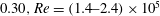 $0.30,Re=(1.4{-}2.4)\times 10^{5}$
), is suspected to induce a spiralling flow structure around helical cavity wakes. Further studies utilizing PIV techniques and numerical simulations are hence recommended to analyse and confirm the existence of such or similar flow structures in the vicinity of the helical configuration. Conversely, the induction of a spin about the vertical axis of the sphere to trigger helical wake formation is also a possibility, which can be a potential research topic for future studies.
$0.30,Re=(1.4{-}2.4)\times 10^{5}$
), is suspected to induce a spiralling flow structure around helical cavity wakes. Further studies utilizing PIV techniques and numerical simulations are hence recommended to analyse and confirm the existence of such or similar flow structures in the vicinity of the helical configuration. Conversely, the induction of a spin about the vertical axis of the sphere to trigger helical wake formation is also a possibility, which can be a potential research topic for future studies.
Acknowledgement
We gratefully acknowledge support from King Abdullah University of Science and Technology (KAUST), Office of Competitive Research Funds, under grant URF/1/2621-01-01.
Supplementary movies
Supplementary movies are available at https://doi.org/10.1017/jfm.2017.337.


