


1 Introduction
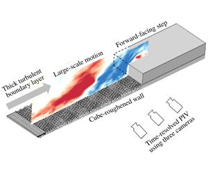
In spite of its geometric simplicity, the forward-facing step (FFS) produces a remarkably complex flow phenomenology of fundamental importance, and is representative of many environmental and engineering applications including the atmospheric turbulent boundary layer (TBL) over low-rise buildings. As illustrated in figure 1, the flow field induced by an FFS features two distinct separation bubbles: one upstream of the step and the other downstream of the leading edge. Both separation bubbles exhibit a flapping motion, i.e. a sequence of seemingly quasi-periodic enlargement and contraction (Pearson, Goulart & Ganapathisubramani Reference Pearson, Goulart and Ganapathisubramani2013; Graziani et al. Reference Graziani, Kerhervé, Martinuzzi and Keirsbulck2018). The unsteadiness inherent in the flapping motion is the source of a variety of undesirable effects, for example, large pressure fluctuations, structural fatigue and acoustic noise (Moss & Baker Reference Moss and Baker1980; Ji & Wang Reference Ji and Wang2010). The buffeting of the upstream separation bubble on the windward face of the step can be particularly catastrophic to structural stability and integrity, and its intermittent spillover onto the step (Stüer, Gyr & Kinzelbach Reference Stüer, Gyr and Kinzelbach1999; Wilhelm, Härtel & Kleiser Reference Wilhelm, Härtel and Kleiser2003; Pearson et al. Reference Pearson, Goulart and Ganapathisubramani2013) implies that the formation and dynamics of the downstream separation bubble are inevitably modulated by the upstream separated shear layer. This paper presents an experimental investigation of the spatio-temporal characteristics of separation bubbles induced by an FFS exposed to a thick turbulent boundary layer with particular focus on the dynamic interaction among the upstream and downstream separation bubbles, and the energetic large-scale motion (LSM) in the oncoming TBL.

Figure 1. Schematic (not to scale) of mean separation bubbles upstream and downstream of an FFS (greyed area), which are denoted by TSBF and TSBT, respectively, for conciseness. The upstream turbulent boundary layer possesses a thickness of  $\unicode[STIX]{x1D6FF}$ and a free-stream velocity of
  $U_{\infty }$. The upstream mean streamwise velocity at the step height is
  $U_{h}$.
Considerable research efforts have been devoted to the study of separated and reattached turbulent flows induced by an FFS. The vast majority of these investigations have focused on the statistical properties of the separation bubble downstream of the leading edge of the step. For example, the effects of Reynolds number and relative boundary layer thickness ( $\unicode[STIX]{x1D6FF}/h$, where
  $\unicode[STIX]{x1D6FF}$ and
  $h$ are thickness of the oncoming TBL and step height, respectively, as in figure 1 on the mean reattachment length and Reynolds stresses were investigated by Sherry, Lo Jacono & Sheridan (Reference Sherry, Lo Jacono and Sheridan2010) and Graziani et al. (Reference Graziani, Lippert, Uystepruyst and Keirsbulck2017). The influence of upstream wall roughness on the mean reattachment length, Reynolds stresses and frequency spectra have been critically examined by Essel et al. (Reference Essel, Nematollahi, Thacher and Tachie2015), Essel & Tachie (Reference Essel and Tachie2017) and Nematollahi & Tachie (Reference Nematollahi and Tachie2018). Meanwhile, the statistics of wall pressure and their connection with vortical structures in the shear layer emanating from the leading edge of an FFS have been studied by Largeau & Moriniere (Reference Largeau and Moriniere2007), Camussi et al. (Reference Camussi, Felli, Pereira, Aloisio and Di Marco2008) and Awasthi et al. (Reference Awasthi, Devenport, Glegg and Forest2014).
To date, detailed investigations of the upstream separation bubble mostly focused on an FFS immersed in a laminar flow. Stüer et al. (Reference Stüer, Gyr and Kinzelbach1999) investigated the three-dimensional (3-D) topology of the separation bubble upstream of an FFS immersed in a fully developed laminar channel flow using hydrogen bubble for flow visualization and particle tracking velocimetry to measure the 3-D velocity field. They observed that the upstream separation bubble is of an ‘open type’, and described a sequence of events in which fluid is entrained into the separation bubble, accumulates across the entire span and is transported parallel to the step. The separation bubble grows in size and the accumulated fluid is continuously released over the step in the form of longitudinal streaks with a quasi-periodicity in the spanwise direction. The 3-D flow topology and dynamics observed by Stüer et al. (Reference Stüer, Gyr and Kinzelbach1999) were confirmed by Wilhelm et al. (Reference Wilhelm, Härtel and Kleiser2003), who performed linear stability analysis and direct numerical simulation (DNS) for flow over an FFS with an upstream fully developed laminar channel flow. Wilhelm et al. (Reference Wilhelm, Härtel and Kleiser2003) concluded that the transition from two-dimensional (2-D) to 3-D flow topology in the step region is not due to absolute instability of the upstream separation bubble, but a manifestation of sensitivity to 3-D perturbation in the oncoming flow. This acute sensitivity of the upstream separation bubble to perturbation in the oncoming flow was also observed in the stability analyses performed by Marino & Luchini (Reference Marino and Luchini2009) and Lanzerstorfer & Kuhlmann (Reference Lanzerstorfer and Kuhlmann2012).
The first experimental investigation of the separation bubble upstream of an FFS submerged in a fully TBL was performed by Pearson et al. (Reference Pearson, Goulart and Ganapathisubramani2013). The relative boundary layer thickness was  $\unicode[STIX]{x1D6FF}/h=1.47$, and the velocity measurements were performed using a time-resolved particle image velocimetry (TR-PIV) system. By using a conditional averaging based on the area of reverse flow, it was shown that the upstream separation bubble exhibits both ‘open’ and ‘closed’ forms, and when of a closed form, the separation bubble occasionally grows in size and spills over the step. The separation bubble oscillates considerably in size, and instances of large separation are preceded by passage of low-velocity region from the oncoming TBL. The dominant frequency of the flapping motion (
 $St_{\infty }=0.09$, where
  $St_{\infty }=fh/U_{\infty }$ is the Strouhal number based on the free-stream velocity
  $U_{\infty }$ and step height
  $h$) of the separation bubble was attributed to LSM in the oncoming TBL.
More recently, Graziani et al. (Reference Graziani, Kerhervé, Martinuzzi and Keirsbulck2018) investigated the dynamics of separation bubbles induced by an FFS immersed in a thin oncoming TBL ( $\unicode[STIX]{x1D6FF}/h=0.49$). The velocity field and wall pressure in both separation bubbles were measured concurrently using a PIV system synchronized with time-resolved wall-pressure transducers, from which a time-resolved velocity field was reconstructed using a linear stochastic estimation. The upstream separation bubble exhibits a flapping motion with a dominant frequency of
  $St_{\infty }=0.027$, which is significantly lower than 0.09 reported for a step submerged in a thicker TBL (Pearson et al. Reference Pearson, Goulart and Ganapathisubramani2013). The downstream separation bubble also exhibits a flapping motion at a frequency of
  $St_{\infty }=0.02$, which is similar to the upstream separation bubble but with a distinct phase difference. Specifically, a contracted downstream separation bubble is preceded by an enlarged upstream separation bubble but with a typical time lag of
  $2h/U_{\infty }$.
In a related study, Fang & Tachie (Reference Fang and Tachie2019b) performed an experimental investigation of turbulent separations over and behind a forward–backward-facing step submerged in a thick TBL ( $\unicode[STIX]{x1D6FF}/h=4.8$) using TR-PIV. It was shown that the separation bubble over the step exhibits a flapping motion at
  $0.075U_{h}/h$ (
 $U_{h}$ is the streamwise mean velocity in the oncoming TBL at the step height), which corresponds to
  $St_{\infty }=0.05$. This frequency coincides with the dominant frequency of the streamwise fluctuating velocity around the step height in the oncoming TBL. Similar to Graziani et al. (Reference Graziani, Kerhervé, Martinuzzi and Keirsbulck2018), the separation bubble behind the step mirrors the flapping motion of separation bubble over the step, but with a distinct time lag of
  $7.6h/U_{h}$.
As summarized in table 1, the frequencies of flapping motion reported in prior investigations are strongly influenced by the nature of the oncoming TBL. A direct connection between the dynamics of the upstream separation bubble and the LSM in the oncoming TBL has been established by Pearson et al. (Reference Pearson, Goulart and Ganapathisubramani2013). However, the interaction between the LSM or upstream separation bubble and the downstream separation bubble was not examined. While the interaction between the upstream and downstream separation bubbles was investigated by Graziani et al. (Reference Graziani, Kerhervé, Martinuzzi and Keirsbulck2018), the effects of oncoming TBL on the unsteadiness of the two separation bubbles were not assessed. Meanwhile, the influence of the oncoming TBL on the flapping motions over and behind a forward–backward-facing step has also been examined in detail by Fang & Tachie (Reference Fang and Tachie2019b), however, the unsteadiness of the upstream separation bubble and its interaction with the TBL and downstream separation bubble were not explored. As such, a comprehensive understanding of the interaction between LSM in a thick oncoming TBL and the separation bubbles induced by FFS is still lacking. Therefore, we conduct an experimental investigation of turbulent flows upstream and downstream of an FFS submerged in a thick TBL ( $\unicode[STIX]{x1D6FF}/h=6.5$) developed over a rough wall. Notably, the imposed mean shear and turbulence intensity at the step height in the oncoming TBL are comparable to those experienced by buildings in realistic atmospheric TBL. The step height was strategically chosen to coincide with the elevation of the most energetic LSM in the oncoming TBL so as to maximize the interaction between oncoming LSM and the separation bubbles induced by FFS. Three high-speed cameras were arranged side by side to simultaneously measure a large field of view that covers both separation bubbles and also capture the LSM in the oncoming TBL.
Table 1. Summary of the relevant previous studies. Strouhal number is defined as  $St_{\infty }\equiv fh/U_{\infty }$, where
  $f$ represents the frequency. The last two columns are the frequencies of flapping motions of separation bubbles upstream (TSBF) and downstream (TSBT) of the step, respectively. The Reynolds number is defined as
  $Re_{h}\equiv hU_{\infty }/\unicode[STIX]{x1D708}$. Symbol – indicates a parameter unavailable in the reference. Superscript
  $(\cdot )^{\ast }$ indicates that this value was not explicitly mentioned in the paper, but is read from the plots.

The remainder of this paper is organized as follows. In § 2, the experimental facility as well as measurement system and procedure are explained. In § 3, the results are analysed in terms of the turbulence statistics as well as the spatio-temporal characteristics of separation bubbles and their association with the oncoming LSM. Finally, major conclusions of this research are summarized in § 4.
2 Experimental set-up
The experiments were performed in an open recirculating water channel located in the Turbulence and Hydraulic Engineering Laboratory (THEL) at the University of Manitoba. The interior dimensions of the test section of the open water channel are 6000 mm, 450 mm and 600 mm, respectively, in the streamwise ( $x$), vertical (
 $y$) and spanwise (
 $z$) directions. The side and bottom walls of the channel were fabricated from smooth 31.8 mm thick Super Abrasion Resistant® transparent acrylic plates that facilitate optical access from all sides. A flow conditioning unit, which comprises a series of honeycomb, perforated plate and mesh screens of different sizes, is installed upstream of the test section to break down the large-scale turbulence and homogenize the flow at the entrance. The water exiting the test section enters a return plenum, which is fitted with a turning vane system to divide and divert the flow exiting the test section. A 30 kW variable-speed drive motor is used to regulate the pump and flow rate.

Figure 2. Schematic of test geometry (not to scale), the adopted coordinate system and fields of view (FOV) of three cameras in (a) bird’s eye view and (b) side view.
Figure 2 shows the schematic of the bottom wall of the test section, FFS, fields of view (FOV) of the cameras and coordinate system adopted in this paper. The origins of the streamwise ( $x$), vertical (
 $y$) and spanwise (
 $z$) coordinates are set at the upstream surface of the FFS, bottom wall and mid-span of the water channel, respectively. The oncoming thick TBL was generated using a combination of toothed barrier and cube roughness. The toothed barrier, which was proposed by Cook (Reference Cook1978) and has been used by Lim, Castro & Hoxey (Reference Lim, Castro and Hoxey2007), is commonly used in the wind-engineering community to simulate atmospheric boundary. More specifically, a toothed barrier is installed at the entrance of the test section to ensure an early turbulence transition, and an aggressive development of the TBL over a cube-roughened plate. The toothed barrier is 75 mm long and its cut outs are of an angle
  $45^{\circ }$, while the depth and pitch are 12 mm and 15 mm, respectively. The cube-roughened plate is 4000 mm long and the cube roughness elements, which are laid out in a staggered pattern, are of side length 3 mm and pitch 6 mm in both the spanwise and streamwise directions. A step of height (
 $h$) 30 mm is installed immediately downstream of the cube-roughened plate. The spanwise (
 $S$) and streamwise (
 $L$) extents of the step are 600 mm and 300 mm, respectively. Based on our previous work (Fang & Tachie Reference Fang and Tachie2019a) in the same facility and similar test condition, the spanwise aspect ratio (
 $S/h=20$) is deemed large enough to neglect the influence of the side walls of the water channel and to ensure a 2-D mean flow at the channel mid-span. We have recently performed measurements for turbulent flows over surface-mounted bluff bodies, which all have the same spanwise aspect ratio
  $S/h=20$, but with different streamwise lengths (
 $L/h\in [1,10]$) submerged in a thick TBL identical to the present study (Chalmers et al. Reference Chalmers, Nyantekyi-Kwakye, Fang and Tachie2019). It was observed that, for the bluff bodies with
  $L/h\geqslant 4$, the influence of the wake flow downstream of the step on the separation bubbles upstream of and over the step is negligible. Therefore, the streamwise extent of the presently employed bluff body (
 $L/h=10$) is long enough to mimic an infinitely long FFS. All solid surfaces within the FOV of the cameras were painted with non-reflective black paint to minimize the distortion of images by surface reflection of laser. The water depth (
 $D$) during the experiment was 430 mm and the free-stream velocity (
 $U_{\infty }$) was
  $0.44~\text{m}~\text{s}^{-1}$. The laboratory temperature was
  $20\,^{\circ }\text{C}$ and the kinematic viscosity of water (
 $\unicode[STIX]{x1D708}$) was
  $10^{-6}~\text{m}^{2}~\text{s}^{-1}$. As such, the Reynolds number based on the step height and free-stream velocity
  $Re_{h}$ (
 $\equiv hU_{\infty }/\unicode[STIX]{x1D708}$) was 13 200. The Froude number (
 $Fr\equiv U_{\infty }/\sqrt{gD}$, where
  $g=9.81~\text{m}~\text{s}^{-2}$ is the gravitational acceleration) was 0.2, as such the free-surface wave was negligible.
A planar TR-PIV was used to measure the velocity field in the streamwise–vertical plane at the channel mid-span. The water was seeded with  $10~\unicode[STIX]{x03BC}\text{m}$ silver coated hollow glass spheres, which had a specific gravity of 1.4. The slip velocity, relaxation time and Stokes number of the seeding particles are
  $2.18\times 10^{-5}~\text{m}~\text{s}^{-1}$,
  $2.2\times 10^{-6}$ s and 0.0014, respectively (see Fang & Tachie (Reference Fang and Tachie2019b)). Therefore, these seeding particles follow the fluid motion well and their velocities reflect the local fluid velocity. A diode pumped dual-cavity dual-head high-speed Neodymium-doped yttrium lithium fluoride (Nd:YLF) laser (wavelength 527 nm) supplied by Photonics Industries International, Inc. was used to illuminate the seeding particles. Each cavity of the laser can deliver a maximum pulse energy of
  $30~\text{mJ}~\text{pulse}^{-1}$ at a frequency of 1000 Hz. During the experiment, both cavities of the laser were triggered simultaneously to maximize the light intensity. High-speed 12-bit complementary metal oxide semiconductor (CMOS) cameras (of resolution 2560 pixel
  $\times$ 1600 pixel and pixel pitch
  $10~\unicode[STIX]{x03BC}\text{m}$) were used to capture the particle images at 807 Hz.
Table 2. List of measurement planes. All measurements were performed in the channel mid-span. Note that planes BL $_{1}$ and BL
 $_{2}$ were measured separately without installing the FFS, and planes FOV
 $_{1}$, FOV
 $_{2}$ and FOV
 $_{3}$ (see figure 2) were measured simultaneously. Plane FOV
 $_{3}$ used a Sigma 105 mm macro lens, and all the other planes used a Nikon 60 mm lens.

Table 2 summarizes the detailed information on all measurement planes, including the notation, FOV range, acquisition frequency, sample size and vector spacing. First, two sets of measurements (planes  $\text{BL}_{1}$ and
  $\text{BL}_{2}$) were performed without installing the FFS to characterize the oncoming TBL. As shown in table 2, plane
  $\text{BL}_{1}$ used a larger FOV to capture the entire thickness of the oncoming TBL, whereas plane
  $\text{BL}_{2}$ used a smaller FOV to assess potential effects of spatial resolution on the flow statistics near the wall region (
 $y/h<3.5$). Subsequently, three cameras (see
  $\text{FOV}_{1}$,
  $\text{FOV}_{2}$ and
  $\text{FOV}_{3}$ in figure 2 and table 2) were used side by side to simultaneously measure the velocity field upstream and downstream of the FFS, covering a large streamwise extent (
 $x/h\in [-12.8,~2.4]$). A Sigma 105 mm macro lens was used for
  $\text{FOV}_{3}$, and a Nikon 60 mm lens was used for all the other measurement planes.
A commercial software (DaVis version 8.4) supplied by LaVision Inc. was used to acquire particle images and calculate the velocity vector fields using a GPU-accelerated multi-pass cross-correlation algorithm. The interrogation area was 128 pixel  $\times$ 128 pixel with 50 % overlapping in the initial pass, and 32 pixel
  $\times$ 32 pixel with 75 % overlapping in the final pass.
In this paper, the instantaneous velocities in the  $x$ and
  $y$ directions are denoted by
  $u$ and
  $v$, respectively. An overbar
  $\overline{(\cdot )}$ and angular brackets
  $\langle \cdot \rangle$ represent temporal and conditional averaging, respectively. An upper case is also used to denote the mean velocities for conciseness, e.g.
  $U\equiv \overline{u}$, while the fluctuating components are represented by the superscript
  $(\cdot )^{\prime }$, e.g.
  $u^{\prime }\equiv u-U$. Subscript
  $(\cdot )_{rms}$ denotes the root-mean-square value, e.g.
  $u_{rms}^{\prime }\equiv \sqrt{\overline{u^{\prime }u^{\prime }}}$.
3 Results and discussion
3.1 Characteristics of oncoming turbulent boundary layer
The salient features of the TBL upstream of the FFS are examined using vertical profiles of streamwise mean velocity ( $U$) and Reynolds stresses (
 $\overline{u^{\prime }u^{\prime }}$,
  $\overline{v^{\prime }v^{\prime }}$ and
  $\overline{u^{\prime }v^{\prime }}$), as well as frequency and wavenumber spectra in figure 3. As shown in figure 3(a,b), the vertical profiles of streamwise mean velocity from planes
  $\text{BL}_{1}$ and
  $\text{BL}_{2}$ (see table 2) are in excellent agreement; however, minor differences are observed in the profiles of Reynolds stresses close to the wall. Specifically, the differences in
  $U$,
$U$,  $\overline{u^{\prime }u^{\prime }}$,
  $\overline{v^{\prime }v^{\prime }}$ and
  $\overline{u^{\prime }v^{\prime }}$ from the two measurement planes at the step height (
 $y/h=1$) are 1 %, 5 %, 15 % and 3 %, respectively. The streamwise mean velocity at the step height (
 $U_{h}$) was
  $0.27~\text{m}~\text{s}^{-1}$, which is 61 % of the free-stream velocity (
 $U_{\infty }$), while the boundary layer thickness (
 $\unicode[STIX]{x1D6FF}$) was 195 mm (or
  $6.5h$). In view of the present oncoming thick TBL,
  $U_{h}$ is a more pertinent velocity scale than
  $U_{\infty }$ (Castro Reference Castro1979; Lim et al. Reference Lim, Castro and Hoxey2007; Fang & Tachie Reference Fang and Tachie2019b), and therefore is used in subsequent data presentation. Following Flack, Schultz & Shapiro (Reference Flack, Schultz and Shapiro2005) and Wu & Christensen (Reference Wu and Christensen2007), the friction velocity (
 $U_{\unicode[STIX]{x1D70F}}$) was estimated using the total shear stress method (i.e.
  $U_{\unicode[STIX]{x1D70F}}\approx (\unicode[STIX]{x1D708}\unicode[STIX]{x2202}U/\unicode[STIX]{x2202}y-\overline{u^{\prime }v^{\prime }})_{max}^{1/2}$) to be
  $0.02~\text{m}~\text{s}^{-1}$. As such,
  $Re_{\unicode[STIX]{x1D70F}}=\unicode[STIX]{x1D6FF}U_{\unicode[STIX]{x1D70F}}/\unicode[STIX]{x1D708}$ was 3900, and the step height expressed using the inner scales was
  $hU_{\unicode[STIX]{x1D70F}}/\unicode[STIX]{x1D708}=590$. The mean shear at the step height, i.e.
  $(\unicode[STIX]{x2202}U/\unicode[STIX]{x2202}y)|_{y=h}h/U_{h}$, was 0.25, which is amongst the highest tested in the existing studies on surface-mounted bluff bodies (Hearst, Gomit & Ganapathisubramani Reference Hearst, Gomit and Ganapathisubramani2016; Essel & Tachie Reference Essel and Tachie2017; Nematollahi & Tachie Reference Nematollahi and Tachie2018; Fang & Tachie Reference Fang and Tachie2019b). Moreover, at the step height (
 $y/h=1$) in the oncoming TBL,
  $u_{rms}^{\prime }/U_{h}=0.145$,
  $v_{rms}^{\prime }/U_{h}=0.086$ and
  $-\overline{u^{\prime }v^{\prime }}/U_{h}^{2}=0.0047$. These turbulence levels are comparable to those (
 $u_{rms}^{\prime }/U_{h}=0.182$,
  $v_{rms}^{\prime }/U_{h}=0.082$ and
  $-\overline{u^{\prime }v^{\prime }}/U_{h}^{2}=0.0035$) reported in the field measurements of realistic atmospheric turbulent boundary layers upstream of surface-mounted cubes (Lim et al. Reference Lim, Castro and Hoxey2007).

Figure 3. Vertical profiles of (a) streamwise mean velocity ( $U$) and (b) Reynolds stresses (
 $\overline{u^{\prime }u^{\prime }}$,
  $\overline{v^{\prime }v^{\prime }}$ and
  $\overline{u^{\prime }v^{\prime }}$) in the oncoming TBL. In (a,b) not all measurement points are plotted for clarity. (c) Contours of premultiplied frequency spectrum of streamwise fluctuating velocity (
 $f\unicode[STIX]{x1D719}_{uu}$) in the oncoming TBL. (d) Four slices in (c) at different vertical locations. In (c,d) the vertical dashed line marks the frequency of
  $St=fh/U_{h}=0.071$. Note that data beyond
  $St=10$ are not presented. (e) Premultiplied spectra of streamwise fluctuating velocity as a function of streamwise wavelength (
 $\unicode[STIX]{x1D706}_{x}$). The wavenumber is defined as
  $k_{x}=2\unicode[STIX]{x03C0}/\unicode[STIX]{x1D706}_{x}$ and the vertical dash-dotted line marks the wavelength
  $\unicode[STIX]{x1D706}_{x}=2.2\unicode[STIX]{x1D6FF}$.
As seen in figure 3(c,d), a distinct peak of premultiplied streamwise frequency spectrum ( $f\unicode[STIX]{x1D719}_{uu}$) occurs in the vicinity of the step height at a frequency
  $St$ (
 $\equiv fh/U_{h}$) of 0.071. It is also observed in figure 3(d) that
  $f\unicode[STIX]{x1D719}_{uu}$ at
  $y/h=1.0$ possesses a sharper peak (at
  $St=0.071$) with a higher magnitude compared to those at lower or higher elevations. Following Rosenberg et al. (Reference Rosenberg, Hultmark, Vallikivi, Bailey and Smits2013), the measured frequency spectrum is converted into wavenumber spectrum using Taylor’s frozen hypothesis (Taylor Reference Taylor1938) with the convection velocity being the local streamwise mean velocity. Figure 3(e) plots the premultiplied wavenumber spectra of streamwise fluctuating velocity as a function of streamwise wavelength (
 $\unicode[STIX]{x1D706}_{x}\equiv 2\unicode[STIX]{x03C0}/k_{x}$). From the figure, a distinct peak of
  $k_{x}\unicode[STIX]{x1D719}_{uu}$ appears close to the step height at the wavelength
  $\unicode[STIX]{x1D706}_{x}\approx 2.2\unicode[STIX]{x1D6FF}$, and the dominance of this wavelength is persistent for
  $y>h$ (equivalently,
  $y>0.15\unicode[STIX]{x1D6FF}$). The wavelength
  $\unicode[STIX]{x1D706}_{x}\approx 2.2\unicode[STIX]{x1D6FF}$ is in good agreement with the characteristic wavelength (2–
 $3\unicode[STIX]{x1D6FF}$) of LSM in TBL at high Reynolds numbers (Adrian, Meinhart & Tomkins Reference Adrian, Meinhart and Tomkins2000; Monty et al. Reference Monty, Hutchins, Ng, Marusic and Chong2009). It should also be noted in figure 3(e) that the energy of LSM is most intense near the step height. The profound effects of oncoming turbulence intensity at the step height on the dynamics of flow separation induced by bluff bodies are well documented in the literature (Castro & Robins Reference Castro and Robins1977; Lim et al. Reference Lim, Castro and Hoxey2007; Hearst et al. Reference Hearst, Gomit and Ganapathisubramani2016; Nematollahi & Tachie Reference Nematollahi and Tachie2018). Thus, a unique feature of the present experiment is the strategic choice of the step height to coincide with the location of the most energetic LSM, so that the interaction between LSM in the oncoming TBL and the separation bubbles induced by the step is maximized. The results presented herein will be particularly invaluable to develop a better understanding, prediction and control of turbulent flow separations over bluff bodies such as buildings and freight exposed to realistic atmospheric boundary layers.

Figure 4. Contour of streamwise mean velocity  $U$ superimposed with representative mean streamlines. The dashed isopleths are
  $U=0$.
3.2 Mean flow
Figure 4 shows the mean velocity field in the vicinity of the FFS. Two distinct recirculation regions form upstream of and over the FFS: the turbulent separation bubble in front of the step and the turbulent separation bubble on top of the step are hereafter denoted by TSBF and TSBT, respectively, for conciseness. The separating and reattaching points of TSBF and TSBT are determined as the intersection points of isopleths of  $U=0$ with the walls. In front of the FFS, the mean flow separates from the bottom wall at
  $x/h=-0.85$, and impinges onto the windward face of the FFS at
  $y/h\approx 0.45$. These points of separation and stagnation are in close agreement with the observations by Moss & Baker (Reference Moss and Baker1980), Addad et al. (Reference Addad, Laurence, Talotte and Jacob2003), Camussi et al. (Reference Camussi, Felli, Pereira, Aloisio and Di Marco2008) and Graziani et al. (Reference Graziani, Kerhervé, Martinuzzi and Keirsbulck2018), in spite of the significant differences in the oncoming flow conditions. Mean flow reattachment point for TSBT occurs at
  $x/h=1.6$ over the FFS. This reattachment length is identical to the authors’ result for turbulent flow over a forward–backward-facing step submerged in a similar thick TBL (Fang & Tachie Reference Fang and Tachie2019b). In contrast, Graziani et al. (Reference Graziani, Kerhervé, Martinuzzi and Keirsbulck2018) observed a much longer reattachment length (
 $3.2h$) over the FFS with an oncoming thin TBL. Our shorter reattachment length compared to Graziani et al. (Reference Graziani, Kerhervé, Martinuzzi and Keirsbulck2018) can be attributed to the enhanced momentum mixing due to the stronger oncoming mean shear and turbulence intensity. This deduction is consistent with the observation by Nematollahi & Tachie (Reference Nematollahi and Tachie2018) that enhanced upstream turbulence intensity tends to reduce the reattachment length over the FFS. Furthermore, large magnitudes of
  $U$ appear close to the leading edge in a triangular-shaped area, a clear manifestation of the oncoming flow deflected over the FFS experiencing acceleration (
 $\unicode[STIX]{x2202}U/\unicode[STIX]{x2202}x>0$) and then deceleration (
 $\unicode[STIX]{x2202}U/\unicode[STIX]{x2202}x<0$) along the mean streamlines.
Due to the strong mean streamline curvature and flow acceleration and deceleration, the topological characteristics of the mean shear around the FFS are significantly more complex than that in a canonical TBL, and are investigated in detail in the following. Because of spanwise homogeneity,  $\unicode[STIX]{x2202}U/\unicode[STIX]{x2202}z$,
  $\unicode[STIX]{x2202}V/\unicode[STIX]{x2202}z$,
  $\unicode[STIX]{x2202}W/\unicode[STIX]{x2202}x$,
  $\unicode[STIX]{x2202}W/\unicode[STIX]{x2202}y$ and
  $\unicode[STIX]{x2202}W/\unicode[STIX]{x2202}z$, where
  $W$ and
  $z$ are the spanwise mean velocity and coordinate, respectively, are all zero. As such, the mean shear tensor in the
  $x$–
$x$– $y$ plane (
 $\unicode[STIX]{x1D61A}_{\boldsymbol{x}\boldsymbol{y}}$) represents a complete assessment of all non-zero components of the 3-D mean strain rate tensor, and is decomposed as follows:
 $$\begin{eqnarray}\unicode[STIX]{x1D61A}_{\boldsymbol{x}\boldsymbol{y}}=\left[\begin{array}{@{}cc@{}}{\displaystyle \frac{\unicode[STIX]{x2202}U}{\unicode[STIX]{x2202}x}} & {\displaystyle \frac{1}{2}}\left({\displaystyle \frac{\unicode[STIX]{x2202}U}{\unicode[STIX]{x2202}y}}+{\displaystyle \frac{\unicode[STIX]{x2202}V}{\unicode[STIX]{x2202}x}}\right)\\ {\displaystyle \frac{1}{2}}\left({\displaystyle \frac{\unicode[STIX]{x2202}U}{\unicode[STIX]{x2202}y}}+{\displaystyle \frac{\unicode[STIX]{x2202}V}{\unicode[STIX]{x2202}x}}\right) & {\displaystyle \frac{\unicode[STIX]{x2202}V}{\unicode[STIX]{x2202}y}}\\ \end{array}\right]=\unicode[STIX]{x1D64C}\left[\begin{array}{@{}cc@{}}\unicode[STIX]{x1D70E}_{1} & 0\\ 0 & \unicode[STIX]{x1D70E}_{2}\\ \end{array}\right]\unicode[STIX]{x1D64C}^{\text{T}},\end{eqnarray}$$
 where superscript  $(\cdot )^{\text{T}}$ represents the transpose operator,
 $\unicode[STIX]{x1D70E}_{1}$ and
  $\unicode[STIX]{x1D70E}_{2}$ are two eigenvalues of
  $\unicode[STIX]{x1D61A}_{\boldsymbol{x}\boldsymbol{y}}$, and
  $\unicode[STIX]{x1D64C}$ represents the
  $2\times 2$ matrix of eigenvectors of
  $\unicode[STIX]{x1D61A}_{\boldsymbol{x}\boldsymbol{y}}$. Since
  $\unicode[STIX]{x1D61A}_{\boldsymbol{x}\boldsymbol{y}}$ is real–symmetric, both
  $\unicode[STIX]{x1D70E}_{1}$ and
  $\unicode[STIX]{x1D70E}_{2}$ are real values, and
  $\unicode[STIX]{x1D64C}$ is orthogonal. Moreover,
  $\unicode[STIX]{x1D70E}_{1}+\unicode[STIX]{x1D70E}_{2}=\unicode[STIX]{x2202}U/\unicode[STIX]{x2202}x+\unicode[STIX]{x2202}V/\unicode[STIX]{x2202}y=0$ due to the incompressibility of the experimental fluid (water) and spanwise homogeneity of the mean flow. Therefore,
  $\unicode[STIX]{x1D70E}_{1}$ and
  $\unicode[STIX]{x1D70E}_{2}$ are inverse to each other, i.e.
  $\unicode[STIX]{x1D70E}_{1}=-\unicode[STIX]{x1D70E}_{2}$. Without loss of generality,
  $\unicode[STIX]{x1D70E}_{1}$ is hereafter defined to be the positive eigenvalue of
  $\unicode[STIX]{x1D61A}_{\boldsymbol{x}\boldsymbol{y}}$, reflecting the magnitude of principal stretching. As such, the first column of
  $\unicode[STIX]{x1D64C}$ defines the direction of principal stretching. Note that for convenience, we restrict the direction of principal stretching to be within
  $[-90^{\circ },90^{\circ }]$, since the opposite direction is also the principal axis.

Figure 5. (a) Contour of the magnitude of principal stretching ( $\unicode[STIX]{x1D70E}_{1}$), superimposed with the directional vectors of the principal stretching and representative mean streamlines. (b) Magnifies (a) in the region over the step. (c) Variation of the magnitudes (
 $\unicode[STIX]{x1D70E}_{1}$) and angles (
 $\unicode[STIX]{x1D703}_{p}$) of the principal stretching and mean velocity (
 $\unicode[STIX]{x1D703}_{u}$) with the
  $x$ coordinate along the dashed streamline in (a). In (a), the values of
  $\unicode[STIX]{x1D703}_{p}$ switch signs along the marked dash-dotted straight line above the top surface, which is inclined with the
  $x$ axis at
  $29^{\circ }$. Not all measurement points are plotted for clarity.
The salient features of the mean shear are assessed in figure 5. The principal stretching is strongest in the region very close to the leading edge along the separating streamline, but becomes weaker further downstream. In the region sufficiently upstream of the FFS (say  $x/h\leqslant -2$), the angle between the direction of principal stretching and the
  $x$ coordinate (
 $\unicode[STIX]{x1D703}_{p}$) is almost uniform in the vertical direction at
  $45^{\circ }$. This is because, in this region,
  $\unicode[STIX]{x2202}U/\unicode[STIX]{x2202}y$ is the dominant velocity gradient, similar to the scenario in a canonical TBL. In the region below the step height (
 $y/h<1$), the direction of principal stretching becomes steeper as the step is approached. In the recirculation region in front of the FFS, for instance, the principal stretching is almost vertical. In the region
  $y/h\in [1,2]$ directly above the leading edge, the principal stretching is uniformly aligned in the streamwise direction (
 $\unicode[STIX]{x1D703}_{p}\approx 0$), indicating the dominance of diagonal components (
 $\unicode[STIX]{x2202}U/\unicode[STIX]{x2202}x$ and
  $\unicode[STIX]{x2202}V/\unicode[STIX]{x2202}y$) of
  $\unicode[STIX]{x1D61A}_{\boldsymbol{x}\boldsymbol{y}}$ in this region. It is also noted in figure 5(a,b) that the direction of principal stretching varies abruptly along the marked straight line, which is inclined at approximately
  $29^{\circ }$ with the
  $x$ axis.
Assuming that the small-scale vortices are convected by the mean flow, the variation of principal stretching along the mean streamlines can provide important insight into the evolution of oncoming small-scale vortical structures. Thus, in figure 5(c), we show the variation of the magnitude of principal stretching ( $\unicode[STIX]{x1D70E}_{1}$), as well as the angles of principal stretching (
 $\unicode[STIX]{x1D703}_{p}$) and mean velocity (
 $\unicode[STIX]{x1D703}_{u}$) along a mean streamline traced through a point very close to the leading edge (
 $(x/h,y/h)=(0,1.1)$). This particular mean streamline is chosen because it encompasses both TSBF and TSBT, and is also close to the region where the strongest principal stretching occurs. Evidently, in the region
  $x/h<-1.2$,
  $\unicode[STIX]{x1D703}_{u}\approx 0$ and
  $\unicode[STIX]{x1D703}_{p}\approx 45^{\circ }$, similar to the canonical TBL. As the mean streamline is deflected upwards (
 $\unicode[STIX]{x1D703}_{u}>0$) downstream of
  $x/h=-1.2$, the principal stretching becomes steeper. In the region
  $x/h\in [-0.6,-0.25]$,
  $\unicode[STIX]{x1D703}_{u}$ and
  $\unicode[STIX]{x1D703}_{p}$ level out at approximately
  $50^{\circ }$ and
  $65^{\circ }$, respectively. At the location of
  $x/h=-0.25$, the value of
  $\unicode[STIX]{x1D70E}_{1}$ exhibits a sharp peak. These observations indicate that the principal stretching becomes stronger and more aligned with the local mean streamline as the FFS is approached. The distributions of
  $\unicode[STIX]{x1D703}_{p}$ and
  $\unicode[STIX]{x1D70E}_{1}$ both decrease sharply and attain minimal values at
  $x/h\approx 0.2$. Meanwhile, the value of
  $\unicode[STIX]{x1D703}_{p}$ reaches a second peak at
  $80^{\circ }$ at
  $x/h=0.4$ before decreasing to
  $45^{\circ }$ further downstream.
It is well known that the vortical structures in turbulent shear flows are most amplified when aligned with the principal stretching, and most suppressed when perpendicular to the principal stretching (Jiménez Reference Jiménez1991). For instance, Moin & Kim (Reference Moin and Kim1985) and Blackburn, Mansour & Cantwell (Reference Blackburn, Mansour and Cantwell1996) showed that the fluctuating vorticity in the outer layer of a turbulent channel flow tends to be at 45 $^{\circ }$ with the streamwise direction, which is aligned in the principal stretching direction. In view of this and the vertical principal stretching within TSBF in figure 5(a), it is expected that the vortices aligned in the vertical direction are amplified within TSBF. This deduction is consistent with the observation by Fang & Tachie (Reference Fang and Tachie2019b) that, as the low-velocity streaky structure approaches a forward–backward-facing step, the vertical component of the counter-rotating vortices is significantly enhanced. Stüer et al. (Reference Stüer, Gyr and Kinzelbach1999), Wilhelm et al. (Reference Wilhelm, Härtel and Kleiser2003) and Lanzerstorfer & Kuhlmann (Reference Lanzerstorfer and Kuhlmann2012) showed that the vertically aligned helical streamlines (accompanied by vertical vortical motion) released from TSBF pass over the leading edge in a streaky motion, which is in the form of streamwise elongated vortices. This observation is in line with the vertically aligned principal stretching immediately upstream of the FFS, and the streamwise principal stretching directly above the leading edge, as seen in figure 5(a).
Slightly upstream of the leading edge of the step, the magnitude of principal stretching is strongest, while the disparity between the principal stretching direction and mean streamline is the smallest (figure 5c). This implies that, upstream of the leading edge, there is a strong tendency that vortices aligned with the mean streamline are enhanced. On the other hand, the principal stretching changes direction abruptly along the marked straight edge in figure 5(a). Consequently, the orientation of vortical structures can drastically change along the marked edge in figure 5(a).
3.3 Turbulence statistics
Figure 6(a,c,e) shows the spatial variations of Reynolds stresses  $\overline{u^{\prime }u^{\prime }}$,
  $\overline{u^{\prime }v^{\prime }}$ and
  $\overline{v^{\prime }v^{\prime }}$, respectively. All Reynolds stresses in the vicinity of the FFS are significantly enhanced compared to the corresponding upstream values (see figure 3b). As marked by symbols (
 $+$ and
  $\times$) in the panels, all three Reynolds stresses possess two distinct local peaks: one upstream of the FFS (
 $+$) and the other downstream of the leading edge very close to the separating streamline (
 $\times$). Note that the marked local peaks in figure 6(a,c) are also included in figure 6(e) to facilitate comparison. From figure 6(e), it is interesting to observe that the upstream local peaks of the Reynolds stresses are aligned in a straight line at
  $40^{\circ }$ with the streamwise direction, whereas the downstream local peaks are located along a horizontal straight line approximately at the highest elevation of the mean separating streamline. As seen in figure 6(c), positively valued
  $\overline{u^{\prime }v^{\prime }}$ appears in a small area close to the leading edge and along the mean separating streamline. This area of positively valued
  $\overline{u^{\prime }v^{\prime }}$ is commonly observed in turbulent flows over an FFS (Sherry et al. Reference Sherry, Lo Jacono and Sheridan2010; Essel & Tachie Reference Essel and Tachie2017; Graziani et al. Reference Graziani, Kerhervé, Martinuzzi and Keirsbulck2018; Nematollahi & Tachie Reference Nematollahi and Tachie2018), and is shown to be inconsistent with the Boussinesq eddy-viscosity assumption (Hattori & Nagano Reference Hattori and Nagano2010; Fang & Tachie Reference Fang and Tachie2019b).

Figure 6. Contours of Reynolds stresses in the Cartesian coordinate system (a,c,e) and curvilinear coordinate system (b,d,f) along the mean streamlines. See the legend for the plotted component in each panel. The solid lines are representative mean streamlines, and the dashed isopleth is forward fraction  $\unicode[STIX]{x1D6FE}=0.5$. Symbols
  $+$ and
  $\times$ mark the local peaks of Reynolds stresses upstream of the FFS and near the separating streamline, respectively, and the peak values are written beside the symbols. To facilitate a direct comparison, the marked local peak locations in (a,c) are also included in (e), whereas the marked local peak locations in (b,d) are also included in (f). Note in (f) that the black
  $\times$ symbol and the number beside it indicate the local peak of
  $(\overline{v^{\prime }v^{\prime }})_{t}$. The dash-dotted straight line marks the boundary where the angle of principal stretching (
 $\unicode[STIX]{x1D703}_{p}$) switches sign, as in figure 5(a).
As seen in figure 6(c), the dual local peak values ( $-0.049U_{h}^{2}$ and
  $-0.054U_{h}^{2}$) of
  $\overline{u^{\prime }v^{\prime }}$ are fairly close to each other, and so are the peak values (
 $0.078U_{h}^{2}$ and
  $0.082U_{h}^{2}$) of
  $\overline{v^{\prime }v^{\prime }}$ in figure 6(e). The downstream peak values of
  $\overline{u^{\prime }v^{\prime }}$ and
  $\overline{v^{\prime }v^{\prime }}$, which correspond to
  $-0.020U_{\infty }^{2}$ and
  $0.031U_{\infty }^{2}$, respectively, are in close agreement with those reported by Ren & Wu (Reference Ren and Wu2011), Essel et al. (Reference Essel, Nematollahi, Thacher and Tachie2015), Graziani et al. (Reference Graziani, Kerhervé, Martinuzzi and Keirsbulck2018) and Nematollahi & Tachie (Reference Nematollahi and Tachie2018) in spite of the drastically different oncoming flow conditions. However, these previous studies showed that the upstream peaks of
  $\overline{u^{\prime }v^{\prime }}$ and
  $\overline{v^{\prime }v^{\prime }}$ are either non-existent or much weaker than the corresponding downstream peaks. The existence of distinct upstream peaks in
  $\overline{u^{\prime }v^{\prime }}$ and
  $\overline{v^{\prime }v^{\prime }}$ with magnitude comparable to the downstream peaks is perhaps a consequence of the extreme oncoming turbulence and the location of the most energetic LSM relative to the step height.
The Reynolds stresses shown in figure 6(a,c,e) reflect the variance and co-variance of fluctuating velocity components along the streamwise and vertical directions without consideration to the acute streamline curvature induced by the FFS. An alternative, and perhaps more insightful, analysis of the Reynolds stress topology is to adopt a curvilinear coordinate system  $(x_{t},y_{t})$ relative to the mean streamlines. Here,
  $x_{t}$ is along the mean streamline, while
  $y_{t}$ is orthogonal to the
  $x_{t}$ axis in the anti-clockwise direction. The Reynolds stresses in the
  $x_{t}$–
 $y_{t}$ coordinate system can be calculated as follows:
 $$\begin{eqnarray}\displaystyle & \displaystyle (\overline{u^{\prime }u^{\prime }})_{t}=\overline{u^{\prime }u^{\prime }}\cos ^{2}(\unicode[STIX]{x1D703}_{u})+\overline{v^{\prime }v^{\prime }}\sin ^{2}(\unicode[STIX]{x1D703}_{u})+\overline{u^{\prime }v^{\prime }}\sin (2\unicode[STIX]{x1D703}_{u}), & \displaystyle\end{eqnarray}$$
 $$\begin{eqnarray}\displaystyle & \displaystyle (\overline{u^{\prime }v^{\prime }})_{t}=\overline{u^{\prime }v^{\prime }}\cos (2\unicode[STIX]{x1D703}_{u})-(\overline{u^{\prime }u^{\prime }}-\overline{v^{\prime }v^{\prime }})\sin (2\unicode[STIX]{x1D703}_{u})/2, & \displaystyle\end{eqnarray}$$
 $$\begin{eqnarray}\displaystyle & \displaystyle (\overline{v^{\prime }v^{\prime }})_{t}=\overline{v^{\prime }v^{\prime }}\cos ^{2}(\unicode[STIX]{x1D703}_{u})+\overline{u^{\prime }u^{\prime }}\sin ^{2}(\unicode[STIX]{x1D703}_{u})-\overline{u^{\prime }v^{\prime }}\sin (2\unicode[STIX]{x1D703}_{u}), & \displaystyle\end{eqnarray}$$
 where the subscript  $(\cdot )_{t}$ denotes the parameter in the transformed curvilinear coordinate system.
Figure 6(b,d,f) shows the contours of Reynolds stresses transformed into the  $x_{t}$–
 $y_{t}$ coordinate system. Similar to Reynolds stresses in the Cartesian coordinate system, the local peaks of
  $(\overline{u^{\prime }u^{\prime }})_{t}$,
  $(\overline{u^{\prime }v^{\prime }})_{t}$ and
  $(\overline{v^{\prime }v^{\prime }})_{t}$ very close to the separating streamline over the step persist. By comparing figure 6(c,d), the positively valued
  $\overline{u^{\prime }v^{\prime }}$ coincides with the negatively valued
  $(\overline{u^{\prime }v^{\prime }})_{t}$ near the leading edge. This indicates that the positively valued
  $\overline{u^{\prime }v^{\prime }}$ near the leading edge in figure 6(c) is merely an artefact of misalignment of mean streamline and the predefined
  $x$ axis. A similar conclusion was made by Fang & Tachie (Reference Fang and Tachie2019b) for turbulent flows over a forward–backward-facing step. Positively valued
  $(\overline{u^{\prime }v^{\prime }})_{t}$ also occurs near the isopleth of
  $\unicode[STIX]{x1D6FE}=0.5$ over the FFS, which is because
  $\unicode[STIX]{x1D703}_{u}\approx -90^{\circ }$ in the vicinity of
  $\unicode[STIX]{x1D6FE}=0.5$ so that
  $(\overline{u^{\prime }v^{\prime }})_{t}\approx -\overline{u^{\prime }v^{\prime }}$. It is also interesting to see in figure 6(f) that the upstream local peaks of transformed Reynolds stresses are displaced upstream compared to Reynolds stresses in the Cartesian coordinate system (see figure 6e), but are almost along the same mean streamline and align in a straight line at
  $34^{\circ }$ with the
  $x$ axis.
It is noted in figure 6 that all Reynolds stresses (in either the Cartesian or curvilinear coordinate system) are strongest over the FFS, except for  $(\overline{v^{\prime }v^{\prime }})_{t}$. In fact, when viewed from the curvilinear coordinate system, the upstream peak magnitudes of
  $(\overline{u^{\prime }u^{\prime }})_{t}$ and
  $(\overline{u^{\prime }v^{\prime }})_{t}$ are decreased by 38 % and 16 %, respectively, while the upstream peak of
  $(\overline{v^{\prime }v^{\prime }})_{t}$ is increased by 47 %. Moreover, the upstream local peak of
  $(\overline{v^{\prime }v^{\prime }})_{t}$ is 53 % larger than that near the separating streamline over the step. By comparing figure 6(b,f), the upstream local peak of
  $(\overline{v^{\prime }v^{\prime }})_{t}$ is also larger than
  $(\overline{u^{\prime }u^{\prime }})_{t}$ in this vicinity. This is in sharp contrast to the canonical TBL, where the streamwise Reynolds normal stress is always larger than the magnitudes of other Reynolds stresses.
It is also interesting to note that the upstream local peak location of  $(\overline{v^{\prime }v^{\prime }})_{t}$ is fairly close to that of
  $\overline{u^{\prime }v^{\prime }}$. At this local peak location, the mean streamline is approximately at
  $45^{\circ }$ with the
  $x$ axis, i.e.
  $\unicode[STIX]{x1D703}_{u}\approx 45^{\circ }$ (see figure 5a). It should be noted that
  $\overline{u^{\prime }v^{\prime }}$ and
  $(\overline{v^{\prime }v^{\prime }})_{t}$ are related as follows:
 $$\begin{eqnarray}\overline{u^{\prime }v^{\prime }}=[(\overline{u^{\prime }u^{\prime }})_{t}-(\overline{v^{\prime }v^{\prime }})_{t}]\sin (2\unicode[STIX]{x1D703}_{u})/2+(\overline{u^{\prime }v^{\prime }})_{t}\cos (2\unicode[STIX]{x1D703}_{u}).\end{eqnarray}$$
 If we further account for the observation that at this particular upstream location,  $(\overline{v^{\prime }v^{\prime }})_{t}$ is much larger than
  $(\overline{u^{\prime }u^{\prime }})_{t}$, the above equation reduces to
  $\overline{u^{\prime }v^{\prime }}\approx -(\overline{v^{\prime }v^{\prime }})_{t}/2$, which is consistent with the observation in figure 6(c,f). From figure 6, the marked dash-dotted straight line, which is the boundary where the principal stretching switches direction abruptly over the step (see figure 5a), well demarcates the upstream and downstream zones of elevated Reynolds stresses (in either coordinate system).

Figure 7. Contours of (a)  $\overline{u^{\prime }u^{\prime }u^{\prime }}$, (b)
  $\overline{u^{\prime }u^{\prime }v^{\prime }}$, (c)
  $\overline{v^{\prime }v^{\prime }u^{\prime }}$, (d)
  $\overline{v^{\prime }v^{\prime }v^{\prime }}$, (e)
  $(\overline{v^{\prime }v^{\prime }u^{\prime }})_{t}$ and (f)
  $(\overline{v^{\prime }v^{\prime }v^{\prime }})_{t}$ in the vicinity of the FFS. The solid line is the separating streamline, and the dashed isopleth is forward fraction
  $\unicode[STIX]{x1D6FE}=0.5$. The dash-dotted straight line marks the boundary where the angle of principal stretching (
 $\unicode[STIX]{x1D703}_{p}$) switches sign, as in figure 5(a).
The third-order moments of the fluctuating velocities are plotted in figure 7 to provide insight into the turbulent transport of Reynolds stresses. The values of  $\overline{u^{\prime }u^{\prime }u^{\prime }}$ and
  $\overline{u^{\prime }u^{\prime }v^{\prime }}$ reflect the transport of instantaneous Reynolds normal stress
  $u^{\prime }u^{\prime }$ by
  $u^{\prime }$ and
  $v^{\prime }$, respectively, whereas
  $\overline{v^{\prime }v^{\prime }u^{\prime }}$ and
  $\overline{v^{\prime }v^{\prime }v^{\prime }}$ measure the transport of
  $v^{\prime }v^{\prime }$ by
  $u^{\prime }$ and
  $v^{\prime }$, respectively. From figure 7(a–d), all the third-order moments switch signs along the mean separating streamline. This suggests that strong values of
  $u^{\prime }u^{\prime }$ or
  $v^{\prime }v^{\prime }$ tend to occur in conjunction with ejection (
 $u^{\prime }<0$ and
  $v^{\prime }>0$) and sweep (
 $u^{\prime }>0$ and
  $v^{\prime }<0$) events, respectively, above and below the mean separating streamline over the FFS. The switching of dominance of ejection and sweep events along the separating streamline was also observed by Elyasi & Ghaemi (Reference Elyasi and Ghaemi2019) in a turbulent separation bubble induced by an adverse pressure gradient.
The third-order moments of the fluctuating velocities are also examined in the curvilinear coordinate system. Here, we are particularly interested in the strong values of  $(\overline{v^{\prime }v^{\prime }})_{t}$ upstream of the leading edge of the FFS. To this end, figure 7(e,f) shows, respectively, the distribution of
  $(\overline{v^{\prime }v^{\prime }u^{\prime }})_{t}$ and
  $(\overline{v^{\prime }v^{\prime }v^{\prime }})_{t}$, which are calculated as follows:
 $$\begin{eqnarray}\displaystyle (\overline{v^{\prime }v^{\prime }u^{\prime }})_{t} & = & \displaystyle \overline{v^{\prime }v^{\prime }u^{\prime }}\cos ^{3}(\unicode[STIX]{x1D703}_{u})+\overline{u^{\prime }u^{\prime }u^{\prime }}\cos (\unicode[STIX]{x1D703}_{u})\sin ^{2}(\unicode[STIX]{x1D703}_{u})-2\overline{u^{\prime }u^{\prime }v^{\prime }}\sin (\unicode[STIX]{x1D703}_{u})\cos ^{2}(\unicode[STIX]{x1D703}_{u})\nonumber\\ \displaystyle & & \displaystyle +\,\overline{u^{\prime }u^{\prime }v^{\prime }}\sin ^{3}(\unicode[STIX]{x1D703}_{u})+\overline{v^{\prime }v^{\prime }v^{\prime }}\cos ^{2}(\unicode[STIX]{x1D703}_{u})\sin (\unicode[STIX]{x1D703}_{u})-2\overline{u^{\prime }v^{\prime }v^{\prime }}\sin ^{2}(\unicode[STIX]{x1D703}_{u})\cos (\unicode[STIX]{x1D703}_{u}),\end{eqnarray}$$
 $$\begin{eqnarray}\displaystyle (\overline{v^{\prime }v^{\prime }v^{\prime }})_{t} & = & \displaystyle \overline{v^{\prime }v^{\prime }v^{\prime }}\cos ^{3}(\unicode[STIX]{x1D703}_{u})-3\overline{u^{\prime }v^{\prime }v^{\prime }}\cos ^{2}(\unicode[STIX]{x1D703}_{u})\sin (\unicode[STIX]{x1D703}_{u})\nonumber\\ \displaystyle & & \displaystyle -\,3\overline{u^{\prime }u^{\prime }v^{\prime }}\sin ^{2}(\unicode[STIX]{x1D703}_{u})\cos (\unicode[STIX]{x1D703}_{u}).\end{eqnarray}$$
 It is observed that both  $(\overline{v^{\prime }v^{\prime }u^{\prime }})_{t}$ and
  $(\overline{v^{\prime }v^{\prime }v^{\prime }})_{t}$ switch sign near the mean separating streamline over the step. According to figures 6(f) and 7(f), both
  $(\overline{v^{\prime }v^{\prime }})_{t}$ and
  $(\overline{v^{\prime }v^{\prime }v^{\prime }})_{t}$ peak around the same location very close to the leading edge, and the peak value of
  $(\overline{v^{\prime }v^{\prime }v^{\prime }})_{t}$ is positive. It is also noted that the magnitudes of
  $(\overline{v^{\prime }v^{\prime }v^{\prime }})_{t}$ are apparently larger than that of
  $(\overline{v^{\prime }v^{\prime }u^{\prime }})_{t}$ upstream of the FFS. These observations suggest that, upstream of the FFS, the dominant flow structure possesses strong positively valued
  $v_{t}^{\prime }$. All the third-order moments exhibit a local peak upstream of the marked inclined straight line, which corresponds to the boundary where the angle of principal stretching suddenly switches sign, and the isopleths are generally extended along the direction of the marked straight line. It is also noted that, in the region above the mean separating streamlines over the step, the magnitudes of
  $\overline{u^{\prime }u^{\prime }v^{\prime }}$ are generally comparable with those of
  $(\overline{u^{\prime }u^{\prime }v^{\prime }})_{t}$, whereas the magnitudes of
  $(\overline{v^{\prime }v^{\prime }v^{\prime }})_{t}$ are significantly larger than
  $\overline{v^{\prime }v^{\prime }v^{\prime }}$.
3.4 Spatial coherence upstream of the FFS
The spatial coherence of turbulence structures is examined using the two-point correlation function, which can be expressed as follows:
 $$\begin{eqnarray}R_{\unicode[STIX]{x1D701}\unicode[STIX]{x1D709}}={\displaystyle \frac{\overline{\unicode[STIX]{x1D701}^{\prime }(\boldsymbol{X}_{ref})\unicode[STIX]{x1D709}^{\prime }(\boldsymbol{X}_{ref}+\unicode[STIX]{x0394}\boldsymbol{X})}}{\unicode[STIX]{x1D701}_{rms}^{\prime }(\boldsymbol{X}_{ref})\unicode[STIX]{x1D709}_{rms}^{\prime }(\boldsymbol{X}_{ref}+\unicode[STIX]{x0394}\boldsymbol{X})}}.\end{eqnarray}$$
 Here,  $\boldsymbol{X}_{ref}$ and
  $\unicode[STIX]{x0394}\boldsymbol{X}$ are the selected reference position and a relative displacement, respectively. In the above equation,
  $\unicode[STIX]{x1D701}$ and
  $\unicode[STIX]{x1D709}$ are two arbitrary variables (such as
  $u$ and
  $u_{t}$). Figure 8(a,b) shows the variation of the two-point autocorrelations
  $R_{uu}$ and
  $R_{vv}$ (with
  $\unicode[STIX]{x1D701}=\unicode[STIX]{x1D709}=u$ and
  $\unicode[STIX]{x1D701}=\unicode[STIX]{x1D709}=v$ in (3.8)) at reference points upstream of the FFS.

Figure 8. Variation of two-point autocorrelations (a)  $R_{uu}$ and (b)
  $R_{vv}$ for the reference points at
  $y/h=1.1$ and
  $x/h=-8.0$,
  $-4.0$ and
  $-0.2$. (c,d) Transformed two-point autocorrelations
  $R_{uu,t}$ and
  $R_{vv,t}$ along the mean streamlines (red solid lines) with the reference point at
  $(x/h,~y/h)=(-0.2,~1.1)$. The isopleths from 0.4 to 0.9 are plotted, and the interval of adjacent isopleths is 0.1. The dash-dotted straight line marks the boundary where the angle of principal stretching (
 $\unicode[STIX]{x1D703}_{p}$) switches sign, as in figure 5(a).
With a reference point sufficiently upstream of the FFS ( $x_{ref}/h\leqslant -4$), the isopleths of
  $R_{uu}$ and
  $R_{vv}$ exhibit patterns similar to those observed in a canonical TBL. For
  $x_{ref}/h\leqslant -4$, the isopleths of
  $R_{uu}$ extend in the streamwise direction and are inclined at
  $15.7^{\circ }$ with the
  $x$ axis, which angle is well within the commonly reported range for canonical TBL over smooth and rough walls (Christensen & Adrian Reference Christensen and Adrian2001; Wu & Christensen Reference Wu and Christensen2010; Liu, Bo & Liang Reference Liu, Bo and Liang2017). These characteristics are commonly attributed to the paradigm of hairpin packets, which consist of multiple hairpin structures aligned in the streamwise direction. For example, Volina, Schultz & Flack (Reference Volina, Schultz and Flack2009) conjectured that the streamwise extent of
  $R_{uu}$ is a manifestation of the convection velocity of each hairpin packet, whereas the inclination of
  $R_{uu}$ reflects the alignment of multiple hairpin heads. Compared to
  $R_{uu}$, the isopleths of
  $R_{vv}$ do not show any clear inclination, and are apparently more compact in both the streamwise and vertical directions, which pattern is similar to that in a canonical TBL (Wu & Christensen Reference Wu and Christensen2010).
With a reference point immediately upstream of the leading edge ( $(x_{ref},~y_{ref})=(-0.2,~1.1)$), the spatial extent of
  $R_{uu}$ is reduced, whereas that of
  $R_{vv}$ is significantly enlarged. It is also noted in figure 8(a,b) that, in the rear part of the depicted correlation functions, the isopleths of
  $R_{uu}$ and
  $R_{vv}$ extend along the marked line and show weak values in the region of TSBT. This pattern is attributed to previous deduction from figure 5(a) that, across the marked straight line, the abrupt change of principal stretching alters the orientation of vortical structures and disrupts the spatial coherence.
In § 3.3, we examined the turbulence statistics in the curvilinear coordinate system along the mean streamlines, and observed that the magnitudes and topology of the Reynolds stresses are substantially different than those in the Cartesian coordinate system. It is, therefore, of interest to assess the spatial coherence of the fluctuating velocity fields ( $u_{t}^{\prime }$ and
  $v_{t}^{\prime }$) in this coordinate system. Figure 8(c,d) shows the two-point autocorrelations
  $R_{uu,t}$ and
  $R_{vv,t}$ (with
  $\unicode[STIX]{x1D701}=\unicode[STIX]{x1D709}=u_{t}$ and
  $\unicode[STIX]{x1D701}=\unicode[STIX]{x1D709}=v_{t}$ in (3.8)) in the
  $x_{t}$–
 $y_{t}$ coordinate system with the reference point close to the peak location of
  $(\overline{v^{\prime }v^{\prime }})_{t}$. Evidently,
  $R_{vv,t}$ possesses a larger spatial extent compared to
  $R_{uu,t}$, especially along the mean streamlines. The plotted
  $R_{vv,t}$ also shows a tendency to elongate parallel to the marked dash-dotted straight line. It was deduced from figure 5 that principal stretching tends to enhance vortices parallel with the mean streamline slightly upstream of the leading edge of the step. As a consequence, vortices (which consist of
  $v_{t}^{\prime }$ and spanwise fluctuating velocity) aligned with the mean streamlines are dominant in the immediate vicinity of the leading edge. This explains the small extension of
  $R_{uu,t}$ (figure 8c) and large extension of
  $R_{vv,t}$ (figure 8d) as well as the excessively strong upstream peak of
  $(\overline{v^{\prime }v^{\prime }})_{t}$ observed in figure 6(f).

Figure 9. LSE based on positively valued  $v_{t}^{\prime }$ at the reference point
  $(x_{ref},~y_{ref})=(-0.2,~1.1)$ (marked as a cross symbol). The vectors are normalized to be of unity length. Representative mean streamlines are also superimposed for reference. Not all vectors are plotted for clarity.
Thus far, the significance of positively valued  $v_{t}^{\prime }$ immediately upstream of the leading edge has been established in figures 6–8. To further examine the coherent structure associated with the positively valued
  $v_{t}^{\prime }$, the linear stochastic estimation (LSE) proposed by Adrian & Moin (Reference Adrian and Moin1988) and defined in (3.9) is employed.
 $$\begin{eqnarray}\langle \unicode[STIX]{x1D709}(\boldsymbol{X}_{ref}+\unicode[STIX]{x0394}\boldsymbol{X})|v_{t}^{\prime }(\boldsymbol{X}_{ref})\rangle ={\displaystyle \frac{\overline{v_{t}^{\prime }(\boldsymbol{X}_{ref})\unicode[STIX]{x1D709}(\boldsymbol{X}_{ref}+\unicode[STIX]{x0394}\boldsymbol{X})}}{\overline{v_{t}^{\prime }(\boldsymbol{X}_{ref})v_{t}^{\prime }(\boldsymbol{X}_{ref})}}}v_{t}^{\prime }(\boldsymbol{X}_{ref}).\end{eqnarray}$$
 Here,  $\unicode[STIX]{x1D709}$ is either
  $u^{\prime }$ or
  $v^{\prime }$. Figure 9 shows the directional field of LSE conditioned on positively valued
  $v_{t}^{\prime }$ at the same reference point as figure 8(d). From the figure, as positively valued
  $v_{t}^{\prime }$ occurs at the selected reference point, positively valued
  $u^{\prime }$ only appears for
  $x/h<-4$, while the negatively valued
  $u^{\prime }$ persists until the right boundary of
  $\text{FOV}_{3}$ outside TSBT. As such, the area of negatively valued
  $u^{\prime }$ surrounding the reference point in figure 9 spans at least 6.4
 $h$ (approximately
  $\unicode[STIX]{x1D6FF}$) in the streamwise direction. This large area of negatively valued
  $u^{\prime }$ is attributed to the low-velocity region of LSM leaning over the FFS. Therefore, the strong peak of
  $(\overline{v^{\prime }v^{\prime }})_{t}$ upstream of the leading edge (see figure 6f) is a manifestation of the upcoming energetic LSM. It should also be noted in figure 9 that, as the low-velocity region of LSM leans over the FFS, positively valued
  $u^{\prime }$ can occur in the near-wall region of the rear part of TSBT (
 $x/h>1.0$).
3.5 Unsteadiness of turbulent separation bubbles
We now turn our attention to the unsteady characteristics of TSBF and TSBT, and the mutual interaction between these two separation bubbles. Following Pearson et al. (Reference Pearson, Goulart and Ganapathisubramani2013), Graziani et al. (Reference Graziani, Kerhervé, Martinuzzi and Keirsbulck2018) and Fang & Tachie (Reference Fang and Tachie2019b), the instantaneous reverse flow area (the summation of areas possessing negatively valued  $u$) is used to quantify the size of instantaneous separation bubbles. More specifically, the temporal variation of reverse flow areas in front of (
 $A_{F}(t)$) and over (
 $A_{T}(t)$) the FFS are, respectively, calculated as follows:
 $$\begin{eqnarray}A_{F}(t)=\int _{\unicode[STIX]{x1D6FA}_{1}}\mathscr{H}[u(\boldsymbol{X},t)]\,\text{d}\forall ,\end{eqnarray}$$
 $$\begin{eqnarray}A_{T}(t)=\int _{\unicode[STIX]{x1D6FA}_{2}}\mathscr{H}[u(\boldsymbol{X},t)]\,\text{d}\forall .\end{eqnarray}$$
 In the above equations, an auxiliary function is defined as  $\mathscr{H}(\unicode[STIX]{x1D709})=0$ if
  $\unicode[STIX]{x1D709}\geqslant 0$ while it is
  $\mathscr{H}(\unicode[STIX]{x1D709})=1$ if
  $\unicode[STIX]{x1D709}<0$, and
  $u(\boldsymbol{X},t)$ denotes the streamwise velocity at the location
  $\boldsymbol{X}$ and time
  $t$;
$t$;  $\text{d}\forall$ represents the grid area centred at
  $\boldsymbol{X}$. In the above equations, the designated integral areas
  $\unicode[STIX]{x1D6FA}_{1}$ and
  $\unicode[STIX]{x1D6FA}_{2}$ are, respectively,
  $x/h\times y/h\in [-4.0,0]\times [0,2.8]$ and
  $x/h\times y/h\in [0,2.4]\times [1.0,2.2]$.

Figure 10. Probability density function (PDF) of reverse flow areas (a) in front of and (b) over the FFS, which are denoted by  $A_{F}$ and
  $A_{T}$, respectively. In (a), an arrow marks the monotonic variation as
  $\unicode[STIX]{x1D6FF}/h$ increases.
In figure 10, the probability density functions (PDF) of reverse flow areas in front of ( $A_{F}$) and over (
 $A_{T}$) the FFS are plotted and compared to available data from the literature. As indicated by the right tail of the PDF of
  $A_{F}$, the probability of enlarged TSBF is a strong function of the oncoming TBL, and monotonically increases with increasing relative boundary layer thickness (
 $\unicode[STIX]{x1D6FF}/h$). Pearson et al. (Reference Pearson, Goulart and Ganapathisubramani2013) concluded that an enlarged TSBF ensues from impingement of oncoming low-velocity regions of streamwise elongated structure on the FFS. Based on this conclusion, the longer right tail of the PDF of
  $A_{F}$ in the present study would imply that the influence of the oncoming elongated structure on TSBF is stronger in the present study than that in Pearson et al. (Reference Pearson, Goulart and Ganapathisubramani2013) and Graziani et al. (Reference Graziani, Kerhervé, Martinuzzi and Keirsbulck2018). This is attributed to the energetic LSM at the step height in the oncoming TBL (see figure 3e). As seen in figure 10(b), the present PDF of
  $A_{T}$ possesses a shorter right tail compared to Fang & Tachie (Reference Fang and Tachie2019b) for the separation bubble over a forward–backward-facing step submerged in a similar oncoming TBL. The increased probability of an enlarged separation bubble is likely due to the influence of the separation bubble in the wake region behind the forward–backward-facing step in Fang & Tachie (Reference Fang and Tachie2019b). It is also noted in figure 10 that reverse flow may completely (at least to the measurement uncertainty) disappear upstream of and over the FFS. Although the mean reattachment lengths upstream and downstream of the step in the present study are close to those in Graziani et al. (Reference Graziani, Kerhervé, Martinuzzi and Keirsbulck2018) and Fang & Tachie (Reference Fang and Tachie2019b), the PDFs of
  $A_{F}$ and
  $A_{T}$ exhibit noticeable differences. This suggests that the effects of upstream and downstream conditions on TSBF and TSBT are more evident in the unsteady characteristics than in the mean properties of the separation bubbles.

Figure 11. (a) Premultiplied frequency spectra of reverse flow in front of the step ( $A_{F}$) and on top of the step (
 $A_{T}$). The three vertical dashed lines from left to right mark the frequencies of
  $St=0.047$,
  $0.070$ and 0.170, respectively. (b) Temporal cross-correlation,
  $R_{FT}(\unicode[STIX]{x0394}t)$, of fluctuating components
  $A_{F}^{\prime }$ and
  $A_{T}^{\prime }$. The three vertical dashed lines from left to right mark the time intervals of
  $\unicode[STIX]{x0394}tU_{h}/h=-7.4$,
  $0.0$ and
  $9.4$, respectively.
To assess the temporal characteristics of TSBF and TSBT, figure 11 plots the premultiplied frequency spectra of fluctuating components of reverse flow areas ( $A_{F}^{\prime }=A_{F}-\overline{A_{F}}$ and
  $A_{T}^{\prime }=A_{T}-\overline{A_{T}}$), as well as the associated temporal cross-correlation, which is defined as
 $$\begin{eqnarray}R_{FT}(\unicode[STIX]{x0394}t)=\overline{A_{F}^{\prime }(t)A_{T}^{\prime }(t+\unicode[STIX]{x0394}t)}/(A_{F,rms}^{\prime }A_{T,rms}^{\prime }).\end{eqnarray}$$
 Evidently,  $A_{T}$ possesses a dominant frequency at
  $St=0.070$ and a subdominant frequency at
  $St=0.170$. The dominant frequency coincides with the dominant frequency of
  $u^{\prime }$ at the step height in the oncoming TBL (see figure 3(c,d)). These dual peaks in the frequency of TSBT are very similar to the observation by Fang & Tachie (Reference Fang and Tachie2019b). Specifically, Fang & Tachie (Reference Fang and Tachie2019b) studied the unsteadiness of the separation bubbles over and behind a forward–backward-facing step submerged in a thick TBL (
 $\unicode[STIX]{x1D6FF}/h=4.8$). They observed that the separation bubble over the forward–backward-facing step has two characteristic frequencies: a dominant frequency at
  $St=0.07$ associated with the flapping motion induced by the upstream LSM, and a subdominant frequency at
  $St=0.14$ corresponding to the periodic appearance of dual separation bubbles over the step, which they termed a separation bubble breakup event. It is observed in figure 11(a) that
  $f\unicode[STIX]{x1D719}_{FF}$ possesses a sharp peak at
  $St=0.047$, which is comparatively lower than the frequency (
 $St=0.071$) of LSM at the step height in the oncoming TBL. As seen in figure 11(b), the value of
  $R_{FT}$ is generally positive for
  $\unicode[STIX]{x0394}t<0$ and negative for
  $\unicode[STIX]{x0394}t>0$. In contrast, Graziani et al. (Reference Graziani, Kerhervé, Martinuzzi and Keirsbulck2018) observed that the value of
  $R_{FT}$ reaches a negative minimum at about
  $\unicode[STIX]{x0394}t=-2h/U_{h}$ (note that their
  $U_{h}=U_{\infty }$) for an FFS with an oncoming thin TBL (
 $\unicode[STIX]{x1D6FF}/h\approx 0.49$).

Figure 12. (a) Joint probability function (JPDF) of  $A_{F}^{\prime }$ and
  $A_{T}^{\prime }$. (b) Premultiplied phase-shifted co-spectra
  $\unicode[STIX]{x1D719}_{FT}^{ps}(f,\unicode[STIX]{x0394}t=-7.4h/U_{h})$ and
  $\unicode[STIX]{x1D719}_{FT}^{ps}(f,\unicode[STIX]{x0394}t=9.4h/U_{h})$, where the vertical dash-dotted line marks the frequency
  $St=0.045$.
Figure 12(a) shows joint probability function (JPDF) of  $A_{F}^{\prime }$ and
  $A_{T}^{\prime }$. There is a high probability for both TSBF and TSBT to shrink simultaneously. Following Fang & Tachie (Reference Fang and Tachie2019b), the phase-shift co-spectrum, which is expressed in (3.13), is used to further understand the contribution to the peak values of
  $R_{FT}$ from different frequencies.
 $$\begin{eqnarray}\unicode[STIX]{x1D719}_{FT}^{ps}(f,\unicode[STIX]{x0394}t)=\overline{\widehat{A_{F}}(f)[\widehat{A_{T}}(f)\exp (2\unicode[STIX]{x03C0}\text{i}f\unicode[STIX]{x0394}t)]^{\divideontimes }}+\overline{\widehat{A_{F}}^{\divideontimes }(f)\widehat{A_{T}}(f)\exp (2\unicode[STIX]{x03C0}\text{i}f\unicode[STIX]{x0394}t)}~.\end{eqnarray}$$
 Here,  $\widehat{(\cdot )}$ and
  $(\cdot )^{\divideontimes }$ denote the Fourier coefficient and complex conjugate, respectively, so that,
  $R_{FT}(\unicode[STIX]{x0394}t)=\int \unicode[STIX]{x1D719}_{FT}^{ps}(f,\unicode[STIX]{x0394}t)\,\text{d}f$. Figure 12(b) plots
  $\unicode[STIX]{x1D719}_{FT}^{ps}(f,\unicode[STIX]{x0394}t=-7.4h/U_{h})$ and
  $\unicode[STIX]{x1D719}_{FT}^{ps}(f,\unicode[STIX]{x0394}t=9.4h/U_{h})$ using the premultiplied scale. These two values of
  $\unicode[STIX]{x0394}t$ are associated with the positive and negative peaks of
  $R_{FT}(\unicode[STIX]{x0394}t)$ in figure 11(b). It is evident in figure 12(b) that both spectra peak at the frequency
  $St=0.045$, which is identical to the peak frequency of
  $f\unicode[STIX]{x1D719}_{FF}$ in figure 11(a). Therefore, the positive and negative peaks in
  $R_{FT}$ (see figure 11b) are primarily contributed by the low-frequency (
 $St=0.045$) motion.
3.6 Effects of the oncoming LSM
The LSM in a canonical TBL has been extensively studied from different perspectives, including its amplitude and frequency modulations of small-scale motions (Mathis, Hutchins & Marusic Reference Mathis, Hutchins and Marusic2009; Ganapathisubramani et al. Reference Ganapathisubramani, Hutchins, Monty, Chung and Marusic2012) and bursting process (Vinuesa et al. Reference Vinuesa, Hites, Wark and Nagib2015). Inspired by these studies, we investigate the influence of oncoming LSM on Reynolds stresses and unsteadiness of separation bubbles in this section.
3.6.1 Effect of LSM on Reynolds stresses
Figure 13 shows the premultiplied frequency spectra ( $\unicode[STIX]{x1D719}_{uu}$,
  $\unicode[STIX]{x1D719}_{uv}$ and
  $\unicode[STIX]{x1D719}_{vv}$) at the points
  $(x/h,y/h)=(0.6,1.3)$ and
  $(x/h,y/h)=(1.1,1.3)$. These two points are selected because they are close to the peak locations of
  $\overline{u^{\prime }u^{\prime }}$ and
  $\overline{u^{\prime }v^{\prime }}$, respectively. It is seen from the figure that
  $f\unicode[STIX]{x1D719}_{uu}$ possesses two distinct peak frequencies, and the lower peak frequencies (
 $St=0.06$ and 0.09) are close to the peak frequency of the oncoming LSM. Additionally, both
  $f\unicode[STIX]{x1D719}_{vv}$ and
  $f\unicode[STIX]{x1D719}_{uv}$ peak at the frequency
  $St\approx 0.6$. This frequency is an order of magnitude higher than the peak frequencies of
  $f\unicode[STIX]{x1D719}_{uu}$ in the oncoming TBL.

Figure 13. Premultiplied frequency spectra at  $x/h=$ (a) 0.6 and (b) 1.1 with
  $y/h=1.3$.

Figure 14. Contours of Reynolds stresses contributed by the fluctuating velocities at low ( $St<0.12$), medium (
 $0.12<St<0.3$) and high (
 $St>0.3$) frequencies, which are denoted by subscripts
  $(\cdot )_{L}$,
  $(\cdot )_{M}$ and
  $(\cdot )_{H}$, respectively. A few representative streamlines are also plotted for reference. The dash-dotted straight line marks the boundary where the angle of principal stretching (
 $\unicode[STIX]{x1D703}_{p}$) switches sign, as in figure 5(a).
In view of the distinct peak frequencies observed in figure 13, it is of interest to further study the spatial characteristics of turbulence motions at different frequencies. We partition the turbulence motions into three frequency regimes as follows:  $St<0.12$,
  $0.12\leqslant St\leqslant 0.3$ and
  $St>0.3$ as the low-, medium- and high-frequency regimes, respectively. These frequency regimes are chosen so that the low and high peak frequencies (
 $St\approx 0.07$ and 0.6) observed in figure 13 are well contained in the low- and high-frequency regimes, respectively. Different thresholds between these regimes (for example,
  $St<0.1$,
  $0.1\leqslant St\leqslant 0.4$ and
  $St>0.4$) have been also tried and only minor differences were observed in the results. It is also noted that the frequency (
 $St<0.12$) demarcating the low-frequency regime corresponds to
  $\unicode[STIX]{x1D706}_{t}U_{\infty }/\unicode[STIX]{x1D6FF}>2.1$ (where
  $\unicode[STIX]{x1D706}_{t}\equiv 1/f$), which is similar to that (
 $\unicode[STIX]{x1D706}_{t}U_{\infty }/\unicode[STIX]{x1D6FF}>2$) used by Ganapathisubramani et al. (Reference Ganapathisubramani, Hutchins, Monty, Chung and Marusic2012) to extract LSM for their TBL.
Figure 14 shows the contribution from all the three different frequency regimes to the Reynolds stresses, where the subscripts  $(\cdot )_{L}$,
  $(\cdot )_{M}$ and
  $(\cdot )_{H}$ denote the fluctuating components in the low-, medium- and high-frequency regimes, respectively. In general, the Reynolds stresses in the medium-frequency regime are insignificant compared to those in the other frequency regimes. From the figures, the Reynolds stresses in the low-frequency regime exhibit local peaks upstream of the FFS, whereas those in the high-frequency regime possess peaks over the FFS. This suggests that the local peaks upstream of the FFS (see figure 6a,c,e) are mostly induced by the low-frequency regime. This deduction is also consistent with the conclusion from figure 9 that the strong value of
  $(\overline{v^{\prime }v^{\prime }})_{t}$, which is a function of Reynolds stresses in the Cartesian coordinate system (see (3.4)), upstream of the leading edge is associated with the structure of the low-velocity region of LSM leaning over the FFS. Therefore, the local peaks of Reynolds stresses upstream of the FFS shown in figure 6(a,c,e) are manifestation of the interaction between LSM in the oncoming TBL with the FFS. The marked dash-dotted straight line, where the principal stretching switches orientation abruptly (see figure 5a), well separates the zones of elevated Reynolds stresses in different frequency regimes. The effects of a strong incoming LSM on Reynolds stresses are mostly evident upstream of the marked line in the low-frequency regime. In the high-frequency regime, on the other hand, the areas of elevated Reynolds stresses are centred around the highest elevation of the mean separating streamline over the step. This is a commonly observed feature for separated shear layer induced by an FFS irrespective of the oncoming flow conditions (Ren & Wu Reference Ren and Wu2011; Essel et al. Reference Essel, Nematollahi, Thacher and Tachie2015; Graziani et al. Reference Graziani, Kerhervé, Martinuzzi and Keirsbulck2018; Nematollahi & Tachie Reference Nematollahi and Tachie2018). This suggests that the inherent characteristic of shear layer emanating from the leading edge is not strongly influenced by the incoming energetic LSM.
3.6.2 Effect of LSM on the unsteadiness of separation bubbles

Figure 15. Conditionally averaged (a)  $\langle A_{F}^{\prime }(\unicode[STIX]{x0394}t)\rangle$ and
  $\langle A_{T}^{\prime }(\unicode[STIX]{x0394}t)\rangle$ and (b–e)
  $\langle u^{\prime }(\unicode[STIX]{x0394}t)\rangle$ based on the VITA event at the location
  $(x/h,y/h)=(-4,1)$ and different values of
  $\unicode[STIX]{x0394}t$ in (3.15).
It has been suggested that LSM consists of forward-leaning regions of alternating positive and negative  $u^{\prime }$ with a typical streamwise wavelength of
  $2$–
$2$– $3\unicode[STIX]{x1D6FF}$ (Adrian et al. Reference Adrian, Meinhart and Tomkins2000; Ganapathisubramani et al. Reference Ganapathisubramani, Hutchins, Monty, Chung and Marusic2012). At the interface between regions of positive and negative
  $u^{\prime }$,
  $u^{\prime }$ changes sign abruptly, which is commonly regarded as one of the signatures of a hairpin structure (Adrian et al. Reference Adrian, Meinhart and Tomkins2000). Blackwelder & Kaplan (Reference Blackwelder and Kaplan1976) proposed the variable-interval time-averaging (VITA) technique to identify the event of abrupt sign switching of
  $u^{\prime }$ in temporal signals, which is termed a VITA event following Adrian et al. (Reference Adrian, Meinhart and Tomkins2000). With the present time-resolved velocity data, we use a conditional averaging technique based on the VITA event to identify the interface between positive and negative
  $u^{\prime }$ in LSM, which is defined as follows:
 $$\begin{eqnarray}\unicode[STIX]{x1D70E}_{u^{\prime }}(\boldsymbol{X}_{ref},t,T)={\displaystyle \frac{1}{T}}\int _{t-(1/2)T}^{t+(1/2)T}{u^{\prime }}^{2}(\boldsymbol{X}_{ref},s)\,\text{d}s-\left({\displaystyle \frac{1}{T}}\int _{t-(1/2)T}^{t+(1/2)T}u^{\prime }(\boldsymbol{X}_{ref},s)\,\text{d}s\right)^{2}.\end{eqnarray}$$
 In the above equation,  $\unicode[STIX]{x1D70E}_{u^{\prime }}$ is the local variance between the time interval
  $[t-T/2,t+T/2]$. Following Luchik & Tiederman (Reference Luchik and Tiederman1987) and Bogard & Tiederman (Reference Bogard and Tiederman1986, Reference Bogard and Tiederman1987), the time instant (
 $t_{j}$) of a VITA event at the reference location
  $\boldsymbol{X}_{ref}$ is identified when
  $\unicode[STIX]{x1D70E}_{u^{\prime }}(\boldsymbol{X}_{ref},t_{j},T)>0.4\overline{u^{\prime }u^{\prime }}$ and
  $\unicode[STIX]{x2202}u^{\prime }(\boldsymbol{X}_{ref},t_{j})/\unicode[STIX]{x2202}t>0$. To extract the spatio-temporal characteristics of turbulence structures associated with a VITA event, the following ensemble average of the fluctuating velocity field is calculated:
 $$\begin{eqnarray}\langle \unicode[STIX]{x1D709}(\boldsymbol{X},\unicode[STIX]{x0394}t)\rangle ={\displaystyle \frac{1}{N}}\mathop{\sum }_{j=1}^{N}\unicode[STIX]{x1D709}(\boldsymbol{X},t_{j}+\unicode[STIX]{x0394}t),\end{eqnarray}$$
 where  $N$ represents the total number of VITA events, and
  $\unicode[STIX]{x1D709}$ is either
  $u^{\prime }$ or
  $v^{\prime }$. In the implementation of the above VITA technique,
  $T$ in (3.14) is chosen to be
  $0.07h/U_{h}$, which is the time period of the dominant frequency
  $St=0.07$ in the oncoming TBL. The reference point
  $(x/h,y/h)=(-4,1)$ is chosen to coincide with the step height. By varying the value of
  $\unicode[STIX]{x0394}t$ in (3.15), the evolution of the flow field as a LSM passing over the FFS can be investigated. Figure 15 shows the variation of reverse flow areas upstream and downstream of the FFS, as well as the fluctuating velocity fields, while LSM passes over the FFS.
As seen in figure 15(d), the conditionally averaged streamwise fluctuating velocity  $\langle u^{\prime }\rangle$ switches signs along an inclined edge, passing the selected reference point. The inclination of the edge separating positive and negative
  $\langle u^{\prime }\rangle$ is at approximately 16
 $^{\circ }$. This angle is very close to the 15
 $^{\circ }$ observed by Pearson et al. (Reference Pearson, Goulart and Ganapathisubramani2013) for the low-velocity region upstream of their FFS. It also agrees well with the inclination angle of
  $R_{uu}$ upstream of the FFS, as shown in figure 8(a). Furthermore, there exists a large area of positively valued
  $\langle u^{\prime }\rangle$ that extends 6.2
 $h$ (approximately
  $\unicode[STIX]{x1D6FF}$) in the upstream direction, and an area of negatively valued
  $\langle u^{\prime }\rangle$ extends downstream of the leading edge of the FFS. Therefore, the streamwise length of the alternating pattern of positive and negative
  $u^{\prime }$ is at least 2
 $\unicode[STIX]{x1D6FF}$. These signatures are consistent with the LSM paradigm in a canonical TBL.
In figure 15(b–e), the conditionally averaged flow field is shifted in time to vividly show the spatio-temporal dynamics of LSM as it passes over the FFS. As seen in figure 15(a), TSBF is enlarged and then shrunk as the LSM passes over the FFS. The variational pattern of TSBT, on the other hand, is comparatively more complex. Specifically, the value of  $\langle A_{T}^{\prime }\rangle$ increases monotonically for
  $\unicode[STIX]{x0394}t<-6.7h/U_{h}$, and then undergoes a high-frequency oscillation during the period that
  $\langle A_{F}^{\prime }\rangle >0$. Both
  $\langle A_{F}^{\prime }\rangle$ and
  $\langle A_{T}^{\prime }\rangle$ become negative for
  $\unicode[STIX]{x0394}t>7h/U_{h}$ when the high-velocity region of LSM interacts with the FFS (see figure 15e). This observation is also in line with the common occurrence of simultaneous contraction of TSBT and TSBF indicated in figure 12(a).
Based on figure 15(a), the oncoming LSM can induce an oscillation of TSBT at a frequency higher than that of LSM. This is consistent with the observation in figure 11(a) that TSBT possesses two dominant frequencies ( $St=0.07$ and 0.17). It is also noted in figure 15(a) that the high-frequency oscillation of TSBT only occurs at instances when TSBF is enlarged. The high-frequency (
 $St=0.17$) oscillation of TSBT is due to the appearance of a short-lived (compared to the time scale of LSM) area of positive
  $u^{\prime }$ when the low-velocity region of LSM leans over the FFS. Fang & Tachie (Reference Fang and Tachie2019b) also observed that the short-lived sweep event can lead to dual separation bubbles over the forward–backward-facing step at the frequency
  $St\approx 0.14$. It is also noted that, with either a low- or high-velocity region upstream of the FFS, the positively valued
  $u^{\prime }$ appears within the separation bubble over the FFS. This is in line with the conclusion made from figure 7 that the sweep event dominates within the mean separation bubble over the FFS.
Thus far, we have demonstrated that as the high-velocity region of LSM leans over the step, TSBF and TSBT contract concurrently. However, as the low-velocity region of LSM leans over the step, TSBF is enlarged while TSBT experiences a higher-frequency oscillation. As such, LSM can generate both positive and negative values of  $R_{FT}$, as shown in figure 11(b). In contrast, Graziani et al. (Reference Graziani, Kerhervé, Martinuzzi and Keirsbulck2018) did not observe positively valued
  $R_{FT}$. This is likely due to their oncoming thin TBL (
 $\unicode[STIX]{x1D6FF}/h=0.49$), and as a consequence the incoming LSM is unlikely to concurrently influence TSBF and TSBT as in the present study.

Figure 16. Time sequences of  $-A_{T}$ (note the negative sign) and streamwise velocity at
  $(x/h,y/h)=(0.6,1.3)$, where
  $\overline{u_{L}^{\prime }u_{L}^{\prime }}$ peaks. The black lines show the instantaneous signals, whereas the coloured lines show the filtered signals retaining the frequencies of
  $St<0.12$.
It is interesting to see in figure 14 that, although high levels of  $\overline{u_{L}^{\prime }v_{L}^{\prime }}$ and
  $\overline{v_{L}^{\prime }v_{L}^{\prime }}$ are primarily confined upstream of the marked straight line, there exists a distinct local peak of
  $\overline{u_{L}^{\prime }u_{L}^{\prime }}$ near the mean separating streamline over the step. This is because the uniform-momentum zone of the LSM has weak vorticity so that it is not strongly affected by the abrupt spatial variation of principal stretching. This prompts us to examine the connection between the downstream local peak of
  $\overline{u_{L}^{\prime }u_{L}^{\prime }}$ and the flapping motion of TSBT. To this end, figure 16 compares the temporal variation of
  $u^{\prime }$ at the point where
  $\overline{u_{L}^{\prime }u_{L}^{\prime }}$ peaks and
  $-A_{T}$ (the negative sign is used here to facilitate comparison). The synchronization between these two low-pass filtered signals (retaining frequencies of
  $St<0.12$) is remarkable. In fact, the cross-correlation coefficient,
  $\overline{A_{T,L}^{\prime }u_{L}^{\prime }}/(A_{T,L,rms}^{\prime }u_{L,rms}^{\prime })$, is calculated to be
  $-0.74$. In the literature, different approaches have been used to track the flapping motion of separation bubble. These include the reverse flow areas (Pearson et al. Reference Pearson, Goulart and Ganapathisubramani2013; Graziani et al. Reference Graziani, Kerhervé, Martinuzzi and Keirsbulck2018; Fang & Tachie Reference Fang and Tachie2019a) and the first mode of proper orthogonal decomposition (Humble, Scarano & Van Oudheusden Reference Humble, Scarano and Van Oudheusden2009; Thacker et al. Reference Thacker, Aubrun, Leroy and Devinant2013; Mohammed-Taifour & Weiss Reference Mohammed-Taifour and Weiss2016; Fang & Tachie Reference Fang and Tachie2019b). These approaches all require whole-field measurement. In contrast, the result shown in figure 16 suggests that the flapping motion of the separation bubble over the step can be reliably tracked using the low-pass filtered signal of a single-point measurement. This observation can be particularly useful for flow control strategy based on the real-time flapping motion of TSBT, and has been further explored by the same authors in Fang & Tachie (Reference Fang and Tachie2020).
4 Summary and conclusions
The spatio-temporal dynamics of separation bubbles upstream and downstream of a forward-facing step submerged in a thick oncoming turbulent boundary layer,  $\unicode[STIX]{x1D6FF}/h=6.5$, was investigated using a time-resolved particle image velocimetry. The step height was chosen to coincide with the elevation of dominant frequency of streamwise fluctuating velocity in the oncoming TBL. The unsteady characteristics of the separation bubbles were examined using the reverse flow area, and the influence of the strong turbulence and large-scale motion inherent in the oncoming TBL on the dynamics of the separation bubbles is elucidated. The Reynolds stresses and third-order moments are examined in both the Cartesian and curvilinear (along mean streamlines) coordinate systems.
The orientation of the principal stretching varies drastically in the step region, and changes abruptly from clockwise to counter-clockwise on the step along a distinct edge inclined with the streamwise direction at approximately  $29^{\circ }$. This edge acts as a buffer that isolates the shear layer over the step from the influence of the oncoming TBL. The Reynolds stresses (
 $\overline{u^{\prime }u^{\prime }}$,
  $\overline{u^{\prime }v^{\prime }}$ and
  $\overline{v^{\prime }v^{\prime }}$) and third-order moments (
 $\overline{u^{\prime }u^{\prime }u^{\prime }}$,
  $\overline{u^{\prime }u^{\prime }v^{\prime }}$,
  $\overline{u^{\prime }v^{\prime }v^{\prime }}$ and
  $\overline{v^{\prime }v^{\prime }v^{\prime }}$) all possess dual local peaks: one upstream of the step, and the other over the step. The upstream peak magnitudes of the Reynolds stresses are excessively high compared to the available literature, and the peak locations are aligned in a straight line inclined with the streamwise direction at
  $40^{\circ }$. The downstream peak magnitudes of Reynolds stresses are comparable to those in the literature, and the peak locations are aligned in a horizontal straight line at the highest elevation of the mean separating streamline over the step. The inclined edge, where the principal stretching switches sign over the step, isolates the upstream and downstream zones of elevated Reynolds stresses and third-order moments.
Compared with the Reynolds stresses in the Cartesian coordinate system, the local peaks of the transformed Reynolds stresses ( $(\overline{u^{\prime }u^{\prime }})_{t}$,
  $(\overline{u^{\prime }v^{\prime }})_{t}$ and
  $(\overline{v^{\prime }v^{\prime }})_{t}$) upstream of the step are displaced upstream, and aligned in a straight line inclined at a shallower angle of 34
 $^{\circ }$ with the streamwise direction. Upstream of the step, the peak magnitudes of
  $(\overline{u^{\prime }u^{\prime }})_{t}$ and
  $(\overline{u^{\prime }v^{\prime }})_{t}$ are, respectively, 38 % and 16 % lower than
  $\overline{u^{\prime }u^{\prime }}$ and
  $\overline{u^{\prime }v^{\prime }}$. In contrast,
  $(\overline{v^{\prime }v^{\prime }})_{t}$ is 47 % larger than
  $\overline{v^{\prime }v^{\prime }}$ immediately upstream of the leading edge. Upstream of the step, the fluctuating velocity perpendicular to the mean streamline is stronger than that along the mean streamlines (
 $(\overline{v^{\prime }v^{\prime }})_{t}>(\overline{u^{\prime }u^{\prime }})_{t}$), and spatially more coherent as demonstrated by the two-point autocorrelations (
 $R_{uu,t}$ and
  $R_{vv,t}$) in the curvilinear coordinate system. High levels of
  $(\overline{v^{\prime }v^{\prime }})_{t}$ immediately upstream of the leading edge is primarily contributed by low-velocity region of LSM leaning over the step.
The size of the mean separation bubble upstream of the step compared favourably to the literature; however, the unsteady characteristics of the separation bubble exhibit strong dependence on the nature of the oncoming TBL. For example, instances of massive upstream separation is more probable in the present study compared to Pearson et al. (Reference Pearson, Goulart and Ganapathisubramani2013) and Graziani et al. (Reference Graziani, Kerhervé, Martinuzzi and Keirsbulck2018), both of which investigated an FFS immersed in a much thinner oncoming TBL ( $\unicode[STIX]{x1D6FF}/h=1.47$ and 0.49, respectively) compared to the present study. The frequency of the flapping motion of the upstream separation bubble (
 $St=fh/U_{h}=0.047$) is also drastically different from those reported by Pearson et al. (Reference Pearson, Goulart and Ganapathisubramani2013) and Graziani et al. (Reference Graziani, Kerhervé, Martinuzzi and Keirsbulck2018). The mean separation bubble over the step is substantially reduced by high levels of oncoming mean shear and turbulence intensity. The separation bubble over the step exhibits a dominant low frequency at
  $St=0.070$ that coincides with the dominant frequency in the oncoming TBL at the step height, and a relatively higher subdominant frequency at
  $St=0.170$. As the low-velocity region of LSM passes over the step, the upstream separation bubble is enlarged, meanwhile the separation bubble over the step is enlarged before subsequent high-frequency oscillation. The high-frequency oscillation of the separation bubble over the step is accompanied by a sudden appearance of positively valued
  $u^{\prime }$ over the step while the low-velocity region of the LSM is leaning over the step.
There is a high probability that both separation bubbles are simultaneously reduced in size. The temporal cross-correlation  $R_{FT}(\unicode[STIX]{x0394}t)$ of the reverse flow areas upstream and downstream of the step attains a positive maximum at
  $\unicode[STIX]{x0394}t=-7.4h/U_{h}$ and a negative minimum at
  $\unicode[STIX]{x0394}t=9.4h/U_{h}$. This pattern is at variance with the observation by Graziani et al. (Reference Graziani, Kerhervé, Martinuzzi and Keirsbulck2018) with an oncoming thin TBL that
  $R_{FT}(\unicode[STIX]{x0394}t)$ is persistently negative and reaches a minimum around
  $\unicode[STIX]{x0394}t=-2h/U_{h}$. Both the negative and positive peaks of
  $R_{FT}(\unicode[STIX]{x0394}t)$ are mostly contributed by the unsteadiness of separation bubbles at
  $St=0.045$, which frequency is identical to the flapping motion of upstream separation bubble.
Near the separated shear layer over the step, the premultiplied frequency spectrum  $\unicode[STIX]{x1D719}_{uu}$ exhibits dual peaks, with the lower peak frequency close to the frequency (
 $St=0.070$) of oncoming LSM. On the other hand, the premultiplied frequency spectra
  $\unicode[STIX]{x1D719}_{vv}$ and
  $\unicode[STIX]{x1D719}_{uv}$ both peak around
  $St=0.6$, which is an order of magnitude higher than the dominant frequency of the oncoming LSM. Prompted by this spectral analysis of the Reynolds stresses, the turbulence motions are partitioned into low-, medium- and high-frequency regimes. It was observed that the high levels of Reynolds stresses upstream of the step are exclusively contributed by the low-frequency turbulence motions. Over the step, the high-frequency turbulence motions are the dominant contributor to the peak values of
  $\overline{u^{\prime }v^{\prime }}$ and
  $\overline{v^{\prime }v^{\prime }}$, while both low- and high-frequency turbulence motions contribute almost equally to
  $\overline{u^{\prime }u^{\prime }}$. This observation explains the acute sensitivity of the upstream peaks of the Reynolds stresses to the oncoming flow condition and near universality of
  $\overline{u^{\prime }v^{\prime }}$ and
  $\overline{v^{\prime }v^{\prime }}$ over the step. Over the step, the local peak of low-frequency
  $\overline{u^{\prime }u^{\prime }}$ near the mean separating streamline is directly linked to the flapping motion of separation bubble. Thus, the temporal signal of low-pass filtered streamwise fluctuating velocity at the downstream local peak of low-frequency
  $\overline{u^{\prime }u^{\prime }}$ well tracks the low-frequency flapping motion of the separation bubble over the step.
Acknowledgements
The financial support from Natural Sciences and Engineering Research Council (NSERC) of Canada and Canada Foundation for Innovation (CFI) to M.F.T. is gratefully acknowledged.
Declaration of interests
The authors report no conflict of interest.


