


1 Introduction
The evaporation of a sessile liquid drop has many important practical applications in areas including biomedicine, geophysics and industry. Such applications include DNA mapping and gene-expression analysis, the water cycle and the manufacturing of semiconductor and micro-fluidic devices (see, for example, Oron, Davis & Bankoff Reference Oron, Davis and Bankoff1997; Myers Reference Myers1998; Poulard, Bénichou & Cazabat Reference Poulard, Bénichou and Cazabat2003; Plawsky et al. Reference Plawsky, Ojha, Chatterjee and Wayner2008; Sefiane, David & Shanahan Reference Sefiane, David and Shanahan2008; Bonn et al. Reference Bonn, Eggers, Indekeu, Meunier and Rolley2009; Cazabat & Guéna Reference Cazabat and Guéna2010; Erbil Reference Erbil2012; Semenov et al. Reference Semenov, Trybala, Rubio, Kovalchuk, Starov and Velarde2014, and references therein).
We begin by presenting a brief review of the most relevant literature on drop spreading in the absence of mass transfer. The key complication with modelling the spreading of a partially wetting liquid drop on a solid substrate is that the usual no-slip boundary condition at the solid–liquid boundary is incompatible with the kinematic boundary condition at the liquid–vapour interface. This results in a stress singularity at a moving contact line (Huh & Scriven Reference Huh and Scriven1971). There are various approaches that regularize the stress singularity whilst remaining compatible with a continuum approach (Snoeijer & Andreotti Reference Snoeijer and Andreotti2013). Remarkably, for small values of the regularization parameter, the choice of regularization does not affect the leading-order relationship between the macroscopic and microscopic contact angles (King Reference King2001). We discuss here two of the most commonly used approaches: precursor films and a finite slip length.
The first approach assumes that the liquid has an ultra-thin ‘precursor film’ that wets the substrate ahead of the contact line (Hervet & de Gennes Reference Hervet and de Gennes1984; de Gennes Reference de Gennes1985; Brochard-Wyart et al. Reference Brochard-Wyart, di Meglio, Quére and de Gennes1991; Colinet & Rednikov Reference Colinet and Rednikov2011). A disjoining pressure provides the physical mechanism for the formation of such a layer and for the prescription of an effective microscopic contact angle. This approach essentially removes the contact line, and in so doing regularizes the stress singularity. It is also advantageous due to its compatibility with numerical simulations; the computational domain can be truncated at a finite distance from the drop, where the precursor film does not feel the effects of the drop. Finally, there is experimental evidence that such films exist in at least some parameter regimes (see, for example, Bascom, Cottington & Singleterry Reference Bascom, Cottington and Singleterry1963; Iwamoto & Tanaka Reference Iwamoto and Tanaka2002).
An alternative approach is to resolve the incompatibility between the no-slip and kinematic boundary conditions by allowing some slip on the solid surface. A commonly used slip law is the Navier slip law (Hocking Reference Hocking1976; Voinov Reference Voinov1976), which states that at the solid–liquid boundary, the liquid velocity tangential to the substrate is proportional to the shear stress – the tangential velocity would vanish at some small depth (the slip length) within the substrate. It has been shown that the flow over a rough surface is equivalent to flow over a smooth surface with slip; the effective slip length is then given by the wavelength of the corrugations of the rough surface (Hocking Reference Hocking1976). It is therefore plausible that the molecular effects governing contact-line motion have a macroscopic effect that can be modelled by a continuum model in which the slip length is on the molecular scale (Hocking & Rivers Reference Hocking and Rivers1982). While being based on hypothesis, rather than experimental observation, slip regularizations do have the advantage that the asymptotic structure in the small-slip limit is usually simpler than that of the small-precursor-thickness limit (in part because there is no extra ‘precursor region’). Another advantage of the slip regularization is that the contact line is well defined (a precursor regularization, on the other hand, essentially removes the contact line).
We now move on to discuss the separate problem of modelling mass transfer from a liquid drop or film that wets a solid substrate. This problem is complicated because one must consider the transport of mass, momentum and energy within and between three phases: the solid substrate, the liquid and the surrounding atmosphere. Models involving a ‘full’ treatment of both the liquid and gas phases, i.e. the Navier–Stokes and energy equations for the density, pressure, velocity and temperature fields, are often referred to as ‘two-sided’ models (Dondlinger, Margerit & Dauby Reference Dondlinger, Margerit and Dauby2005; Margerit, Dondlinger & Dauby Reference Margerit, Dondlinger and Dauby2005). To make analytical progress, it is necessary to simplify such a model.
One way to obtain a simpler model is to assume that the gas phase has a negligible influence on the evaporative flux so that we may concentrate solely on the liquid phase. Such models are often referred to as ‘one-sided’ models (Burelbach, Bankoff & Davis Reference Burelbach, Bankoff and Davis1988; Cazabat & Guéna Reference Cazabat and Guéna2010; Murisic & Kondic Reference Murisic and Kondic2011). A particular one-sided model that is often used in the literature is the non-equilibrium one-sided (NEOS) model (see, for example, Cazabat & Guéna Reference Cazabat and Guéna2010; Murisic & Kondic Reference Murisic and Kondic2011), which is based on the assumption that the liquid–gas interface is not at equilibrium and that evaporation is limited by the transfer of molecules across the interface. The mass flux
 $E^{\ast }$
across the interface per unit area per unit time in the NEOS model has the form
$E^{\ast }$
across the interface per unit area per unit time in the NEOS model has the form
 $$\begin{eqnarray}E^{\ast }\propto \frac{1}{h^{\ast }+K},\end{eqnarray}$$
where
 $h^{\ast }$
is the drop thickness and
$h^{\ast }$
is the drop thickness and
 $K$
is a constant. The NEOS model is usually appropriate for the case when the gas phase consists purely of the liquid vapour. Cazabat & Guéna (Reference Cazabat and Guéna2010) noted that the NEOS model may also be appropriate for water drops evaporating into an inert gas; the water–gas interface is susceptible to contamination (so that transfer of molecules across the interface is the rate-limiting step).
$K$
is a constant. The NEOS model is usually appropriate for the case when the gas phase consists purely of the liquid vapour. Cazabat & Guéna (Reference Cazabat and Guéna2010) noted that the NEOS model may also be appropriate for water drops evaporating into an inert gas; the water–gas interface is susceptible to contamination (so that transfer of molecules across the interface is the rate-limiting step).
If the gas phase is assumed to be composed of a mixture of the liquid vapour and an inert gas (such as air), the following simplification of the two-sided model is available. If the gas phase is convection free and its density, viscosity and thermal conductivity are small compared to those of the liquid phase, it is possible to reduce the dynamics of the gas phase to a diffusion equation for the vapour concentration. Such models are often referred to as ‘1.5-sided’ models (Dondlinger et al. Reference Dondlinger, Margerit and Dauby2005; Haut & Colinet Reference Haut and Colinet2005; Margerit et al. Reference Margerit, Dondlinger and Dauby2005; Sultan, Boudaoud & Ben Amar Reference Sultan, Boudaoud and Ben Amar2005). In these models, the transport of vapour is coupled to the Navier–Stokes equations within the liquid via appropriate boundary conditions (Oron et al. Reference Oron, Davis and Bankoff1997).
A 1.5-sided model may be simplified by assuming that the time scale of mass loss is much slower than that of diffusive vapour transport; the diffusion equation for the vapour then reduces to Laplace’s equation. If the liquid–gas interface in the 1.5-sided model is assumed to be at equilibrium, then the boundary-value problem for the vapour concentration is mathematically equivalent to that of determining the electrical potential around a lens-shaped conductor; such models are therefore often referred to as ‘lens’ models in the literature (Cazabat & Guéna Reference Cazabat and Guéna2010; Murisic & Kondic Reference Murisic and Kondic2011). The assumptions leading to the lens model imply that the process limiting evaporation is the diffusion of vapour away from the liquid–gas interface. The equivalent electrostatic problem has been solved by Deegan et al. (Reference Deegan, Bakajin, Dupont, Huber, Nagel and Witten2000) and Popov (Reference Popov2005); Hu & Larson (Reference Hu and Larson2002) showed that an approximation for the resulting mass flux per unit area per unit time has the form
 $$\begin{eqnarray}E^{\ast }\propto \frac{1}{(s^{\ast 2}-r^{\ast 2})^{a}},\quad a=\frac{1}{2}-\frac{{\it\Psi}}{{\rm\pi}},\quad \text{for}~0<{\it\Psi}<\frac{{\rm\pi}}{2},\end{eqnarray}$$
where
 $s^{\ast }$
is the radius of the circular contact set,
$s^{\ast }$
is the radius of the circular contact set,
 $r^{\ast }$
is the distance from the axis of symmetry of the drop and
$r^{\ast }$
is the distance from the axis of symmetry of the drop and
 ${\it\Psi}$
is the microscopic contact angle. Upon making the lubrication approximation for the liquid drop, this expression reduces to
${\it\Psi}$
is the microscopic contact angle. Upon making the lubrication approximation for the liquid drop, this expression reduces to
 $$\begin{eqnarray}E^{\ast }\propto \frac{1}{(s^{\ast 2}-r^{\ast 2})^{1/2}}.\end{eqnarray}$$
The expression (1.3) for the mass flux is common in the literature (see, for example, Deegan et al. Reference Deegan, Bakajin, Dupont, Huber, Nagel and Witten1997, Reference Deegan, Bakajin, Dupont, Huber, Nagel and Witten2000). There is an inverse-square-root singularity at the contact line, but since this singularity is integrable, the total mass flux out of the drop is not singular and physically reasonable predictions for the evolution of the drop volume are obtained even without regularization of the evaporative singularity (Deegan et al. Reference Deegan, Bakajin, Dupont, Huber, Nagel and Witten2000). The lens model is usually appropriate for a gas phase that is a mixture of the liquid vapour and an inert gas (with the notable exception of water, as already discussed). Having made the lubrication approximation for the liquid drop, the problem for the liquid can be simplified to a single fourth-order, nonlinear, parabolic partial differential equation for the liquid thickness profile, subject to appropriate boundary conditions. We shall adopt a lens model, with a mass flux of the form (1.3), in this paper.
Having given a brief introduction to the most relevant literature concerning both drop spreading in the absence of mass loss and the modelling of mass transfer, we now consider the motion of a partially wetting drop as it evaporates. The focus of most theoretical efforts has been numerical simulations in the thin-film regime (see, for example, Anderson & Davis Reference Anderson and Davis1995; Hocking Reference Hocking1995; Ajaev Reference Ajaev2005; Poulard et al. Reference Poulard, Guéna, Cazabat, Boudaoud and Ben Amar2005; Sodtke, Ajaev & Stephan Reference Sodtke, Ajaev and Stephan2007; Dunn et al. Reference Dunn, Wilson, Duffy, David and Sefiane2008, Reference Dunn, Wilson, Duffy, David and Sefiane2009; Murisic & Kondic Reference Murisic and Kondic2008; Fried & Jabbour Reference Fried and Jabbour2012; Semenov et al. Reference Semenov, Trybala, Rubio, Kovalchuk, Starov and Velarde2014; Sáenz et al. Reference Sáenz, Sefiane, Kim, Matar and Valluri2015, and references therein). However, the literature is largely lacking the simplifications and insights that would be gained from a systematic asymptotic analysis. Indeed, Murisic & Kondic (Reference Murisic and Kondic2011) state that ‘Future work should include much more careful treatment of evaporation next to the contact line in the presence of a vapour/inert gas mixture. New asymptotic methods will also need to be developed to connect the nano-scale of relevance to the contact-line physics and the macro-scale of a drop’. In the absence of evaporation, asymptotic approaches have been extremely fruitful (Lacey Reference Lacey1982; Hocking Reference Hocking1983), leading in particular to a systematic derivation of Tanner’s law, and some asymptotic analysis has been carried out on mass-transfer models incorporating simple physics (Savva, Rednikov & Colinet Reference Savva, Rednikov and Colinet2014; Oliver et al. Reference Oliver, Whiteley, Saxton, Vella, Zubkov and King2015).
We now discuss a key feature of experiments that we might hope to understand better by using asymptotic analysis. Experimental studies (see, for example, Cachile et al.
Reference Cachile, Bénichou, Poulard and Cazabat2002; Poulard et al.
Reference Poulard, Bénichou and Cazabat2003) have found that, for various liquids, the drop is axisymmetric with a circular contact set whose radius near to extinction is approximately proportional to the square root of the time remaining until extinction. In other words, the time remaining until extinction is proportional to the square of the diameter
 $d$
of the circular contact set (between the drop and the substrate). This ‘
$d$
of the circular contact set (between the drop and the substrate). This ‘
 $d^{2}$
-law’ is usually attributed to diffusion-limited kinetics (Erbil, McHale & Newton Reference Erbil, McHale and Newton2002) and may be understood using a scaling argument as follows. We assume that the time scale of mass loss is much longer than the time scale of spreading in the absence of mass transfer. We also assume that the microscopic contact angle is constant. A sufficiently small drop will then quickly relax under surface tension to have a constant-curvature profile with a macroscopic contact angle equal to the microscopic contact angle. After this initial transient, on a longer time scale, the drop will lose mass. Assuming that the mass loss is sufficiently small that it does not affect the droplet profile established on the spreading time scale, the volume of the drop scales with
$d^{2}$
-law’ is usually attributed to diffusion-limited kinetics (Erbil, McHale & Newton Reference Erbil, McHale and Newton2002) and may be understood using a scaling argument as follows. We assume that the time scale of mass loss is much longer than the time scale of spreading in the absence of mass transfer. We also assume that the microscopic contact angle is constant. A sufficiently small drop will then quickly relax under surface tension to have a constant-curvature profile with a macroscopic contact angle equal to the microscopic contact angle. After this initial transient, on a longer time scale, the drop will lose mass. Assuming that the mass loss is sufficiently small that it does not affect the droplet profile established on the spreading time scale, the volume of the drop scales with
 $d^{3}$
. For a diffusion-dominated model (such as the lens model described above), the typical vertical scale over which the concentration of vapour decays is the same as the typical radial scale, namely
$d^{3}$
. For a diffusion-dominated model (such as the lens model described above), the typical vertical scale over which the concentration of vapour decays is the same as the typical radial scale, namely
 $d$
, because this decay is governed by Laplace’s equation. The local flux of vapour out of the drop, which is proportional to the normal derivative of the vapour concentration, then scales with
$d$
, because this decay is governed by Laplace’s equation. The local flux of vapour out of the drop, which is proportional to the normal derivative of the vapour concentration, then scales with
 $1/d$
(Ledesma-Aguilar, Vella & Yeomans Reference Ledesma-Aguilar, Vella and Yeomans2014), so that the total mass flux out of the drop (obtained by integrating the local flux over the drop surface) scales linearly with
$1/d$
(Ledesma-Aguilar, Vella & Yeomans Reference Ledesma-Aguilar, Vella and Yeomans2014), so that the total mass flux out of the drop (obtained by integrating the local flux over the drop surface) scales linearly with
 $d$
(see Deegan et al.
Reference Deegan, Bakajin, Dupont, Huber, Nagel and Witten2000). Equating the rate of change of the drop volume with the total mass flux out of the drop therefore gives us the
$d$
(see Deegan et al.
Reference Deegan, Bakajin, Dupont, Huber, Nagel and Witten2000). Equating the rate of change of the drop volume with the total mass flux out of the drop therefore gives us the
 $d^{2}$
-law. We note that the
$d^{2}$
-law. We note that the
 $d^{2}$
-law can also arise from a one-sided model with a uniform evaporation rate, independent of
$d^{2}$
-law can also arise from a one-sided model with a uniform evaporation rate, independent of
 $d$
(Oliver et al.
Reference Oliver, Whiteley, Saxton, Vella, Zubkov and King2015). Near-extinction behaviour differing slightly from the
$d$
(Oliver et al.
Reference Oliver, Whiteley, Saxton, Vella, Zubkov and King2015). Near-extinction behaviour differing slightly from the
 $d^{2}$
-law has also been observed (see, for example, Shahidzadeh-Bonn et al.
Reference Shahidzadeh-Bonn, Rafaï, Azouni and Bonn2006). However, it is not clear whether such behaviour is systematic, or an artefact of experiment.
$d^{2}$
-law has also been observed (see, for example, Shahidzadeh-Bonn et al.
Reference Shahidzadeh-Bonn, Rafaï, Azouni and Bonn2006). However, it is not clear whether such behaviour is systematic, or an artefact of experiment.
In this paper, we apply a systematic asymptotic analysis in the limit of small slip in order to answer the question of how disparate the time scales of mass loss and spreading in the absence of mass loss must be for the scaling argument leading to the
 $d^{2}$
-law to remain valid. We also aim to gain an understanding of the dynamics that determines the extinction time of a thin, evaporating, axisymmetric drop. Of particular interest are the typical phases described in the work of Stauber et al. (Reference Stauber, Wilson, Duffy and Sefiane2014) and seen in the experiments referenced therein – namely, that the drop first evaporates with its contact line being pinned and then later the contact line begins to recede while the contact angle remains constant.
$d^{2}$
-law to remain valid. We also aim to gain an understanding of the dynamics that determines the extinction time of a thin, evaporating, axisymmetric drop. Of particular interest are the typical phases described in the work of Stauber et al. (Reference Stauber, Wilson, Duffy and Sefiane2014) and seen in the experiments referenced therein – namely, that the drop first evaporates with its contact line being pinned and then later the contact line begins to recede while the contact angle remains constant.
We consider a model for the contact-line dynamics of a thin, axisymmetric drop of viscous liquid that partially wets a rigid, flat, impermeable substrate and evaporates into an inert gas. We examine the isothermal regime in which the time scale of vapour diffusion is much smaller than that of liquid motion and in which the density and viscosity of the liquid, the surface tension of the liquid–vapour interface, the microscopic contact angle of the drop, the diffusion coefficient of the vapour and the equilibrium vapour concentration are all constant. We assume that the liquid slips on the substrate according to a generalized Navier slip law, that the vapour immediately above the drop is at thermodynamic equilibrium, and that the flow of liquid within the drop may be modelled using lubrication theory. The effects of, inter alia, gravity, evaporative cooling and vapour recoil are neglected. In § 2, we formulate and non-dimensionalize the thin-film problem. In § 3, we use the method of matched asymptotic expansions to analyse the small-slip limit and answer our central question. In § 4, we summarize our results and outline directions for future work.
2 Formulation
We introduce cylindrical polar coordinates
 $(r^{\ast },z^{\ast })$
measuring the radial distance from the line of symmetry of the axisymmetric drop and the normal distance from the substrate, respectively (here and hereafter, starred variables denote dimensional quantities). The free surface of the drop is denoted by
$(r^{\ast },z^{\ast })$
measuring the radial distance from the line of symmetry of the axisymmetric drop and the normal distance from the substrate, respectively (here and hereafter, starred variables denote dimensional quantities). The free surface of the drop is denoted by
 $z^{\ast }=h^{\ast }(r^{\ast },t^{\ast })$
, where
$z^{\ast }=h^{\ast }(r^{\ast },t^{\ast })$
, where
 $t^{\ast }$
is time. The liquid occupies the region
$t^{\ast }$
is time. The liquid occupies the region
 $0<z^{\ast }<h^{\ast }(r^{\ast },t^{\ast })$
for
$0<z^{\ast }<h^{\ast }(r^{\ast },t^{\ast })$
for
 $0<r^{\ast }<s^{\ast }(t^{\ast })$
, so that
$0<r^{\ast }<s^{\ast }(t^{\ast })$
, so that
 $r^{\ast }=s^{\ast }(t^{\ast })$
is the location of the contact line (where the drop thickness vanishes). The drop thickness profile
$r^{\ast }=s^{\ast }(t^{\ast })$
is the location of the contact line (where the drop thickness vanishes). The drop thickness profile
 $h^{\ast }(r^{\ast },t^{\ast })$
and contact-set radius
$h^{\ast }(r^{\ast },t^{\ast })$
and contact-set radius
 $s^{\ast }(t^{\ast })$
are not known a priori – their determination is a major goal of our analysis. We assume that the liquid is incompressible with a constant density
$s^{\ast }(t^{\ast })$
are not known a priori – their determination is a major goal of our analysis. We assume that the liquid is incompressible with a constant density
 ${\it\rho}$
and that its motion is governed by the Stokes equations with a constant viscosity
${\it\rho}$
and that its motion is governed by the Stokes equations with a constant viscosity
 ${\it\mu}$
and no body forces. (The values of the relevant physical parameters for several liquids are given in table 1.) The microscopic contact angle
${\it\mu}$
and no body forces. (The values of the relevant physical parameters for several liquids are given in table 1.) The microscopic contact angle
 ${\it\Psi}$
between the free boundary and substrate is assumed to be constant and small. The initial drop profile is assumed to be smooth with a small aspect ratio of the order of
${\it\Psi}$
between the free boundary and substrate is assumed to be constant and small. The initial drop profile is assumed to be smooth with a small aspect ratio of the order of
 ${\it\Psi}$
. To leading order in
${\it\Psi}$
. To leading order in
 ${\it\Psi}$
, the radial and normal velocity components,
${\it\Psi}$
, the radial and normal velocity components,
 $u^{\ast }$
and
$u^{\ast }$
and
 $w^{\ast }$
respectively, and the pressure field
$w^{\ast }$
respectively, and the pressure field
 $p^{\ast }$
then satisfy the lubrication equations, given by
$p^{\ast }$
then satisfy the lubrication equations, given by
 $$\begin{eqnarray}\frac{1}{r^{\ast }}\frac{\partial }{\partial r^{\ast }}(r^{\ast }u^{\ast })+\frac{\partial w^{\ast }}{\partial z^{\ast }}=0,\quad \frac{\partial p^{\ast }}{\partial r^{\ast }}={\it\mu}\frac{\partial ^{2}u^{\ast }}{\partial z^{\ast }},\quad \frac{\partial p^{\ast }}{\partial z^{\ast }}=0,\end{eqnarray}$$
for
 $0<z^{\ast }<h^{\ast }(r^{\ast },t^{\ast })$
,
$0<z^{\ast }<h^{\ast }(r^{\ast },t^{\ast })$
,
 $0<r^{\ast }<s^{\ast }(t^{\ast })$
.
$0<r^{\ast }<s^{\ast }(t^{\ast })$
.
Table 1. The values of the physical parameters used in the model for hexane, isopropanol and HFE-7100 at 25 °C and 1 atm (Lide Reference Lide2004; Sultan et al.
Reference Sultan, Boudaoud and Ben Amar2005; Murisic & Kondic Reference Murisic and Kondic2011; Machrafi et al.
Reference Machrafi, Sadoun, Rednikov, Dehaeck, Dauby and Colinet2013; Hadjittofis et al.
Reference Hadjittofis, Lister, Singh and Vella2015). The equilibrium vapour concentration
 $c_{e}$
is evaluated using the saturation vapour pressure and we assume that
$c_{e}$
is evaluated using the saturation vapour pressure and we assume that
 $c_{\infty }=0$
for each of the liquids in the table (since the concentration of these liquid vapours in the atmosphere is negligible).
$c_{\infty }=0$
for each of the liquids in the table (since the concentration of these liquid vapours in the atmosphere is negligible).

The liquid is assumed to slip on the substrate according to a generalized Navier slip law with slip length
 ${\it\Lambda}_{0}^{3-n}(h^{\ast })^{n-2}$
, with
${\it\Lambda}_{0}^{3-n}(h^{\ast })^{n-2}$
, with
 ${\it\Lambda}_{0}$
and
${\it\Lambda}_{0}$
and
 $n$
constant parameters (with
$n$
constant parameters (with
 ${\it\Lambda}_{0}$
having the dimensions of length and
${\it\Lambda}_{0}$
having the dimensions of length and
 $n$
being dimensionless). We delay until later a discussion of which values of
$n$
being dimensionless). We delay until later a discussion of which values of
 $n$
are most physically relevant but note that our model will be shown to be correctly specified for
$n$
are most physically relevant but note that our model will be shown to be correctly specified for
 $n<5/2$
. The substrate is assumed to be impermeable so that the slip and no-flux boundary conditions on the solid–liquid boundary are given, respectively, by
$n<5/2$
. The substrate is assumed to be impermeable so that the slip and no-flux boundary conditions on the solid–liquid boundary are given, respectively, by
 $$\begin{eqnarray}u^{\ast }={\it\Lambda}_{0}^{3-n}(h^{\ast })^{n-2}\frac{\partial u^{\ast }}{\partial z^{\ast }},\quad w^{\ast }=0,\end{eqnarray}$$
on
 $z^{\ast }=0$
,
$z^{\ast }=0$
,
 $0<r^{\ast }<s^{\ast }(t^{\ast })$
.
$0<r^{\ast }<s^{\ast }(t^{\ast })$
.
The traction on the free surface is assumed to be due to a constant surface tension
 ${\it\gamma}$
only. We assume that the drop loses mass through its free boundary at a mass flux
${\it\gamma}$
only. We assume that the drop loses mass through its free boundary at a mass flux
 $E^{\ast }(r^{\ast },t^{\ast })$
per unit area per unit time (about which more shortly). Thus, to leading order in
$E^{\ast }(r^{\ast },t^{\ast })$
per unit area per unit time (about which more shortly). Thus, to leading order in
 ${\it\Psi}$
, the kinematic and dynamic boundary conditions at the liquid–vapour interface are given by
${\it\Psi}$
, the kinematic and dynamic boundary conditions at the liquid–vapour interface are given by
 $$\begin{eqnarray}w^{\ast }=\frac{\partial h^{\ast }}{\partial t^{\ast }}+u^{\ast }\frac{\partial h^{\ast }}{\partial r^{\ast }}+\frac{E^{\ast }}{{\it\rho}},\quad p^{\ast }=-\frac{{\it\gamma}}{r^{\ast }}\frac{\partial }{\partial r^{\ast }}\left(r^{\ast }\frac{\partial h^{\ast }}{\partial r^{\ast }}\right),\quad \frac{\partial u^{\ast }}{\partial z^{\ast }}=0,\end{eqnarray}$$
on
 $z^{\ast }=h^{\ast }(r^{\ast },t^{\ast })$
,
$z^{\ast }=h^{\ast }(r^{\ast },t^{\ast })$
,
 $0<r^{\ast }<s^{\ast }(t^{\ast })$
.
$0<r^{\ast }<s^{\ast }(t^{\ast })$
.
The lubrication equations (2.1) and boundary conditions (2.2)–(2.3) lead in the usual way (see Oron et al. Reference Oron, Davis and Bankoff1997; Myers Reference Myers1998) to the thin-film equation
 $$\begin{eqnarray}\frac{\partial h^{\ast }}{\partial t^{\ast }}+\frac{1}{r^{\ast }}\frac{\partial }{\partial r^{\ast }}(r^{\ast }h^{\ast }\bar{u}^{\ast })=-\frac{E^{\ast }}{{\it\rho}}\quad \text{for}~0<r^{\ast }<s^{\ast }(t^{\ast }),\end{eqnarray}$$
where the depth-averaged radial velocity
 $\bar{u}^{\ast }$
is given by
$\bar{u}^{\ast }$
is given by
 $$\begin{eqnarray}\bar{u}^{\ast }=\frac{{\it\gamma}}{{\it\mu}}\left(\frac{h^{\ast 2}}{3}+{\it\Lambda}_{0}^{3-n}(h^{\ast })^{n-1}\right)\frac{\partial }{\partial r^{\ast }}\left[\frac{1}{r^{\ast }}\frac{\partial }{\partial r^{\ast }}\left(r^{\ast }\frac{\partial h^{\ast }}{\partial r^{\ast }}\right)\right]\quad \text{for}~0<r^{\ast }<s^{\ast }(t^{\ast }).\end{eqnarray}$$
A mixture of liquid vapour and an inert gas occupies the region above the drop and substrate. We assume that the dynamics of the vapour may be reduced to a diffusion equation for the vapour concentration
 $c^{\ast }$
, with constant diffusion coefficient
$c^{\ast }$
, with constant diffusion coefficient
 $D$
. We further assume that the time scale of vapour diffusion is much smaller than the time scale of the liquid motion, so that transport of the vapour is governed by Laplace’s equation, with
$D$
. We further assume that the time scale of vapour diffusion is much smaller than the time scale of the liquid motion, so that transport of the vapour is governed by Laplace’s equation, with
 $$\begin{eqnarray}{\rm\nabla}^{2}c^{\ast }=0\quad \text{for}~z^{\ast }>0;\end{eqnarray}$$
we note that since the vertical extent of the drop is assumed to be much smaller than the radius of the circular contact set of the drop, and the latter is the relevant length scale for the transport of liquid vapour, the gas phase occupies the region
 $z^{\ast }>0$
to leading order in
$z^{\ast }>0$
to leading order in
 ${\it\Psi}$
.
${\it\Psi}$
.
The vapour just above the free surface of the drop is assumed to be at equilibrium and the equilibrium vapour concentration is assumed to take a constant value
 $c_{e}$
. As the substrate is impermeable, there is no flux of vapour through the substrate. Thus, after linearizing the boundary condition on the surface of the drop onto
$c_{e}$
. As the substrate is impermeable, there is no flux of vapour through the substrate. Thus, after linearizing the boundary condition on the surface of the drop onto
 $z^{\ast }=0$
, we obtain, to leading order in
$z^{\ast }=0$
, we obtain, to leading order in
 ${\it\Psi}$
, the mixed boundary conditions
${\it\Psi}$
, the mixed boundary conditions
 $$\begin{eqnarray}\left.\begin{array}{@{}c@{}}\displaystyle c^{\ast }=c_{e}\quad \text{on}~z^{\ast }=0,~0<r^{\ast }<s^{\ast }(t^{\ast });\\ \displaystyle \frac{\partial c^{\ast }}{\partial z^{\ast }}=0\quad \text{on}~z^{\ast }=0,~r^{\ast }>s^{\ast }(t^{\ast }).\end{array}\right\}\end{eqnarray}$$
We assume that the vapour concentration in the far field takes a constant value
 $c_{\infty }$
, so that
$c_{\infty }$
, so that
 $$\begin{eqnarray}c^{\ast }\rightarrow c_{\infty }\quad \text{as}~r^{\ast 2}+z^{\ast 2}\rightarrow \infty ,~z^{\ast }>0.\end{eqnarray}$$
The mixed-boundary-value problem (2.6)–(2.8) has an analogue in electrostatics and may be solved exactly (Weber Reference Weber1873) using a Hankel transform. We deduce that the mass flux
 $E^{\ast }$
per unit area per unit time is given by
$E^{\ast }$
per unit area per unit time is given by
 $$\begin{eqnarray}E^{\ast }(r^{\ast },t^{\ast })=-DM\left.\frac{\partial c^{\ast }}{\partial z^{\ast }}\right|_{z^{\ast }=0}=\frac{2DM(c_{e}-c_{\infty })}{{\rm\pi}(s^{\ast 2}-r^{\ast 2})^{1/2}}\quad \text{for}~0<r^{\ast }<s^{\ast }(t^{\ast }),\end{eqnarray}$$
where
 $M$
is the molar mass of the liquid vapour. Such an inverse-square-root singularity in the evaporative flux is common in the literature (see, for example, Deegan et al.
Reference Deegan, Bakajin, Dupont, Huber, Nagel and Witten1997, Reference Deegan, Bakajin, Dupont, Huber, Nagel and Witten2000; Cachile et al.
Reference Cachile, Bénichou, Poulard and Cazabat2002).
$M$
is the molar mass of the liquid vapour. Such an inverse-square-root singularity in the evaporative flux is common in the literature (see, for example, Deegan et al.
Reference Deegan, Bakajin, Dupont, Huber, Nagel and Witten1997, Reference Deegan, Bakajin, Dupont, Huber, Nagel and Witten2000; Cachile et al.
Reference Cachile, Bénichou, Poulard and Cazabat2002).
Before non-dimensionalizing the model, we identify two important time scales by examining (2.4), (2.5) and (2.9). A balance of the two terms on the left-hand side of the thin-film equation (2.4) gives a typical time scale of capillary action
 ${\it\tau}_{C}$
, while a balance of the first term on the left-hand side with the term on the right-hand side gives a typical time scale of mass loss
${\it\tau}_{C}$
, while a balance of the first term on the left-hand side with the term on the right-hand side gives a typical time scale of mass loss
 ${\it\tau}_{M}$
. We find that
${\it\tau}_{M}$
. We find that
 $$\begin{eqnarray}{\it\tau}_{C}=\frac{3{\it\mu}R}{{\it\Psi}^{3}{\it\gamma}},\quad {\it\tau}_{M}=\frac{{\rm\pi}{\it\Psi}{\it\rho}R^{2}}{2DM(c_{e}-c_{\infty })},\end{eqnarray}$$
where
 $R$
is the initial radius of the circular contact set of the drop, i.e.
$R$
is the initial radius of the circular contact set of the drop, i.e.
 $s^{\ast }(0)=R$
. Typical values of the time scales
$s^{\ast }(0)=R$
. Typical values of the time scales
 ${\it\tau}_{C}$
and
${\it\tau}_{C}$
and
 ${\it\tau}_{M}$
are given for various liquids in table 2.
${\it\tau}_{M}$
are given for various liquids in table 2.
Table 2. In the upper part of the table, we give the typical time scales of capillary action
 ${\it\tau}_{C}$
, spreading/retraction
${\it\tau}_{C}$
, spreading/retraction
 ${\it\tau}_{S}$
(see § 3) and mass loss
${\it\tau}_{S}$
(see § 3) and mass loss
 ${\it\tau}_{M}$
for drops of hexane, isopropanol and HFE-7100 with initial contact-set radii of 1 mm and 0.1 mm. In the middle part of the table, we give the corresponding values of the ratio
${\it\tau}_{M}$
for drops of hexane, isopropanol and HFE-7100 with initial contact-set radii of 1 mm and 0.1 mm. In the middle part of the table, we give the corresponding values of the ratio
 ${\it\alpha}$
of the time scales of capillary action and mass loss, as well as the evaporation-induced capillary number
${\it\alpha}$
of the time scales of capillary action and mass loss, as well as the evaporation-induced capillary number
 $\mathscr{E}$
(defined in (3.8)). In the lower part of the table, we give the value
$\mathscr{E}$
(defined in (3.8)). In the lower part of the table, we give the value
 $R=R_{crit}$
of the initial contact-set radius such that
$R=R_{crit}$
of the initial contact-set radius such that
 $\mathscr{E}=1$
; the analysis of this paper is therefore valid for
$\mathscr{E}=1$
; the analysis of this paper is therefore valid for
 $R>R_{crit}$
(assuming the model to be valid). The values are calculated for drops with microscopic contact angle
$R>R_{crit}$
(assuming the model to be valid). The values are calculated for drops with microscopic contact angle
 ${\it\Psi}=0.1$
, slip exponent
${\it\Psi}=0.1$
, slip exponent
 $n=2$
and slip length
$n=2$
and slip length
 ${\it\Lambda}_{0}=5$
nm; the slip coefficient for all liquids is then
${\it\Lambda}_{0}=5$
nm; the slip coefficient for all liquids is then
 ${\it\lambda}=1.5\times 10^{-4}$
for
${\it\lambda}=1.5\times 10^{-4}$
for
 $R=1$
mm and
$R=1$
mm and
 ${\it\lambda}=1.5\times 10^{-3}$
for
${\it\lambda}=1.5\times 10^{-3}$
for
 $R=0.1$
mm.
$R=0.1$
mm.

We non-dimensionalize by scaling
 $r^{\ast }=Rr$
,
$r^{\ast }=Rr$
,
 $t^{\ast }={\it\tau}_{C}t$
,
$t^{\ast }={\it\tau}_{C}t$
,
 $s^{\ast }=Rs$
and
$s^{\ast }=Rs$
and
 $h^{\ast }={\it\Psi}Rh$
. We obtain thereby the dimensionless thin-film equation
$h^{\ast }={\it\Psi}Rh$
. We obtain thereby the dimensionless thin-film equation
 $$\begin{eqnarray}\frac{\partial h}{\partial t}+\frac{1}{r}\frac{\partial }{\partial r}(rh\bar{u})=-\frac{{\it\alpha}}{(s^{2}-r^{2})^{1/2}}\quad \text{for}~0<r<s(t),\end{eqnarray}$$
where
 $$\begin{eqnarray}\bar{u}=(h^{2}+{\it\lambda}^{3-n}h^{n-1})\frac{\partial }{\partial r}\left[\frac{1}{r}\frac{\partial }{\partial r}\left(r\frac{\partial h}{\partial r}\right)\right],\end{eqnarray}$$
and non-dimensionalization has introduced two dimensionless parameters:
 $$\begin{eqnarray}{\it\lambda}=\frac{3^{1/(3-n)}{\it\Lambda}_{0}}{{\it\Psi}R}\quad \text{and}\quad {\it\alpha}=\frac{{\it\tau}_{C}}{{\it\tau}_{M}}.\end{eqnarray}$$
Here
 ${\it\lambda}$
is the slip coefficient (i.e. the ratio between the slip length and the typical drop thickness) and
${\it\lambda}$
is the slip coefficient (i.e. the ratio between the slip length and the typical drop thickness) and
 ${\it\alpha}$
is the ratio of the time scales of capillary action and mass loss.
${\it\alpha}$
is the ratio of the time scales of capillary action and mass loss.
The modelling assumptions above, together with the assumption that there is no flux of liquid through the contact line, imply that the pertinent boundary conditions for the thin-film equation (2.11) are given by
 $$\begin{eqnarray}\frac{\partial h}{\partial r}=0,\quad rh\bar{u}=0\quad \text{at}~r=0;\quad h=0,\quad -\frac{\partial h}{\partial r}=1,\quad rh\bar{u}=0\quad \text{at}~r=s(t)^{-}.\end{eqnarray}$$
We prescribe an initial drop profile
 $$\begin{eqnarray}h(r,0)=\mathscr{H}(r)\quad \text{for}~0\leqslant r\leqslant s(0)=1,\end{eqnarray}$$
where the function
 $\mathscr{H}(r)$
is chosen to be smooth and positive for
$\mathscr{H}(r)$
is chosen to be smooth and positive for
 $0\leqslant r<1$
and to satisfy the boundary conditions (2.14a−e
).
$0\leqslant r<1$
and to satisfy the boundary conditions (2.14a−e
).
In the absence of mass transfer, a generalized Navier slip law of the form (2.2a
) facilitates contact-line motion for
 $n<3$
; slip laws with
$n<3$
; slip laws with
 $n=1$
and
$n=1$
and
 $n=2$
have been widely used in the literature (see, for example, Hocking Reference Hocking1976; Voinov Reference Voinov1976; Greenspan Reference Greenspan1978; King & Bowen Reference King and Bowen2001). In the case of uniform mass transfer, contact-line motion with such a slip law and a prescribed finite microscopic contact angle has been shown to be possible for
$n=2$
have been widely used in the literature (see, for example, Hocking Reference Hocking1976; Voinov Reference Voinov1976; Greenspan Reference Greenspan1978; King & Bowen Reference King and Bowen2001). In the case of uniform mass transfer, contact-line motion with such a slip law and a prescribed finite microscopic contact angle has been shown to be possible for
 $n<3$
(Oliver et al.
Reference Oliver, Whiteley, Saxton, Vella, Zubkov and King2015). We show in appendix A that the inverse-square-root singularity in the evaporative flux causes the problem (2.11)–(2.14) to be correctly specified for the more restricted range
$n<3$
(Oliver et al.
Reference Oliver, Whiteley, Saxton, Vella, Zubkov and King2015). We show in appendix A that the inverse-square-root singularity in the evaporative flux causes the problem (2.11)–(2.14) to be correctly specified for the more restricted range
 $n<5/2$
. We also see from the local analysis in appendix A that, if
$n<5/2$
. We also see from the local analysis in appendix A that, if
 $2\leqslant n<5/2$
, then the boundary conditions (2.14c,d
) can only be imposed if there is no flux of liquid through the contact line, so that the boundary condition (2.14e
) is in fact redundant in this sense; however, if
$2\leqslant n<5/2$
, then the boundary conditions (2.14c,d
) can only be imposed if there is no flux of liquid through the contact line, so that the boundary condition (2.14e
) is in fact redundant in this sense; however, if
 $n<2$
, then is it necessary to impose (2.14e
) in order for there to be no flux of liquid through the contact line. We shall take general
$n<2$
, then is it necessary to impose (2.14e
) in order for there to be no flux of liquid through the contact line. We shall take general
 $n<5/2$
in our asymptotic analysis of the small-slip limit of (2.11)–(2.15) in § 3, and
$n<5/2$
in our asymptotic analysis of the small-slip limit of (2.11)–(2.15) in § 3, and
 $n=1$
or
$n=1$
or
 $n=2$
in the ensuing numerical simulations that we shall use to illustrate or verify the results of our asymptotic analysis.
$n=2$
in the ensuing numerical simulations that we shall use to illustrate or verify the results of our asymptotic analysis.
We note that integrating the thin-film equation (2.11) from
 $r=0$
to
$r=0$
to
 $r=s(t)$
and applying the no-flux boundary conditions (2.14b,e
) implies that the expression representing global conservation of mass is given by
$r=s(t)$
and applying the no-flux boundary conditions (2.14b,e
) implies that the expression representing global conservation of mass is given by
 $$\begin{eqnarray}\frac{\text{d}V}{\text{d}t}=-2{\rm\pi}{\it\alpha}s,\quad V(t)=2{\rm\pi}\int _{0}^{s(t)}rh(r,t)\,\text{d}r,\end{eqnarray}$$
where
 $V(t)$
is the volume of the drop at time
$V(t)$
is the volume of the drop at time
 $t$
. The volume of the drop is expected to decrease monotonically with time
$t$
. The volume of the drop is expected to decrease monotonically with time
 $t$
until it vanishes at some time
$t$
until it vanishes at some time
 $t=t_{c}$
. We refer to
$t=t_{c}$
. We refer to
 $t_{c}$
as the extinction time and shall see that its determination is important for understanding the behaviour close to extinction.
$t_{c}$
as the extinction time and shall see that its determination is important for understanding the behaviour close to extinction.
3 Asymptotic analysis in the small-slip limit
3.1 Three time scales
In practical scenarios, it is expected that the slip coefficient
 ${\it\lambda}$
is small. We now perform an asymptotic analysis in the small-slip limit
${\it\lambda}$
is small. We now perform an asymptotic analysis in the small-slip limit
 ${\it\lambda}\rightarrow 0$
. We begin with the time scale of capillary action; we will see that on this time scale the contact line does not move and mass is conserved, both to leading order in the limit of small slip. The drop profile will be shown to relax under surface tension from its prescribed initial condition to a profile with constant mean curvature (to leading order in the thin-film limit). Our analysis of the time scale of capillary action will identify a longer time scale on which the contact line moves an order-unity distance. On this longer time scale we will show that, provided
${\it\lambda}\rightarrow 0$
. We begin with the time scale of capillary action; we will see that on this time scale the contact line does not move and mass is conserved, both to leading order in the limit of small slip. The drop profile will be shown to relax under surface tension from its prescribed initial condition to a profile with constant mean curvature (to leading order in the thin-film limit). Our analysis of the time scale of capillary action will identify a longer time scale on which the contact line moves an order-unity distance. On this longer time scale we will show that, provided
 ${\it\alpha}=\mathit{O}({\it\lambda}^{1/2})$
as
${\it\alpha}=\mathit{O}({\it\lambda}^{1/2})$
as
 ${\it\lambda}\rightarrow 0$
, mass is still conserved to leading order and the drop either spreads or recedes under surface tension to an equilibrium leading-order contact-set radius that, loosely speaking, is determined by a balance of capillarity and mass loss in an inner region near the contact line (about which more shortly). On an even longer time scale, we show that the drop starts to lose an order-unity amount of mass and that the leading-order contact-set radius and leading-order drop volume decrease monotonically with time until the drop becomes extinct.
${\it\lambda}\rightarrow 0$
, mass is still conserved to leading order and the drop either spreads or recedes under surface tension to an equilibrium leading-order contact-set radius that, loosely speaking, is determined by a balance of capillarity and mass loss in an inner region near the contact line (about which more shortly). On an even longer time scale, we show that the drop starts to lose an order-unity amount of mass and that the leading-order contact-set radius and leading-order drop volume decrease monotonically with time until the drop becomes extinct.
3.2 Time scale of capillary action
3.2.1 Asymptotic structure
The spatial asymptotic structure on the time scale of capillary action consists of an outer region in which
 $(s-r),~h=\mathit{O}(1)$
as
$(s-r),~h=\mathit{O}(1)$
as
 ${\it\lambda}\rightarrow 0$
, and an inner region near the contact line in which slip becomes important. We see from the expression (2.12) for
${\it\lambda}\rightarrow 0$
, and an inner region near the contact line in which slip becomes important. We see from the expression (2.12) for
 $\bar{u}$
that slip modifies the mobility of the liquid when
$\bar{u}$
that slip modifies the mobility of the liquid when
 $h=\mathit{O}({\it\lambda})$
. Since the (dimensionless) microscopic contact angle is 1, this must occur within a distance of
$h=\mathit{O}({\it\lambda})$
. Since the (dimensionless) microscopic contact angle is 1, this must occur within a distance of
 $\mathit{O}({\it\lambda})$
from the contact line. To match efficiently the contact angle between the outer and inner regions, we introduce an intermediate region, spanning all length scales between them. This spatial asymptotic structure is illustrated in figure 1.
$\mathit{O}({\it\lambda})$
from the contact line. To match efficiently the contact angle between the outer and inner regions, we introduce an intermediate region, spanning all length scales between them. This spatial asymptotic structure is illustrated in figure 1.

Figure 1. Asymptotic regions in the small-slip limit on the time scale of capillary action;
 ${\it\theta}_{0}$
,
${\it\theta}_{0}$
,
 $K_{0}$
and 1 are the leading-order contact angles in the outer (macroscopic), intermediate (mesoscopic) and inner (microscopic) regions, respectively. The remaining contact angle depicted,
$K_{0}$
and 1 are the leading-order contact angles in the outer (macroscopic), intermediate (mesoscopic) and inner (microscopic) regions, respectively. The remaining contact angle depicted,
 ${\it\Phi}_{0}$
, is the leading-order far-field microscopic contact angle which plays the role of an effective microscopic contact angle in the leading-order contact-line law.
${\it\Phi}_{0}$
, is the leading-order far-field microscopic contact angle which plays the role of an effective microscopic contact angle in the leading-order contact-line law.
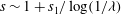
3.2.2 Outer region
We see from the global conservation of mass expression (2.16) that, provided that
 ${\it\alpha}\ll 1$
as
${\it\alpha}\ll 1$
as
 ${\it\lambda}\rightarrow 0$
, mass loss occurs on a longer time scale than capillary action (we note that we shall in fact shortly make a more restrictive assumption on
${\it\lambda}\rightarrow 0$
, mass loss occurs on a longer time scale than capillary action (we note that we shall in fact shortly make a more restrictive assumption on
 ${\it\alpha}$
, namely that
${\it\alpha}$
, namely that
 ${\it\alpha}=\mathit{O}({\it\lambda}^{1/2})$
as
${\it\alpha}=\mathit{O}({\it\lambda}^{1/2})$
as
 ${\it\lambda}\rightarrow 0$
). In the absence of mass transfer, it has been shown that the contact line moves an order-unity distance on a longer time scale
${\it\lambda}\rightarrow 0$
). In the absence of mass transfer, it has been shown that the contact line moves an order-unity distance on a longer time scale
 $t=\mathit{O}(\log (1/{\it\lambda}))$
as
$t=\mathit{O}(\log (1/{\it\lambda}))$
as
 ${\it\lambda}\rightarrow 0$
(Lacey Reference Lacey1982; Hocking Reference Hocking1983). We therefore expand
${\it\lambda}\rightarrow 0$
(Lacey Reference Lacey1982; Hocking Reference Hocking1983). We therefore expand
 $h\sim h_{0}$
,
$h\sim h_{0}$
,
 $s\sim 1+s_{1}/\log (1/{\it\lambda})$
as
$s\sim 1+s_{1}/\log (1/{\it\lambda})$
as
 ${\it\lambda}\rightarrow 0$
. In the outer region in which
${\it\lambda}\rightarrow 0$
. In the outer region in which
 $(s-r),~h=\mathit{O}(1)$
, the evolution of the leading-order film profile
$(s-r),~h=\mathit{O}(1)$
, the evolution of the leading-order film profile
 $h_{0}(r,t)$
is governed by the thin-film equation given by
$h_{0}(r,t)$
is governed by the thin-film equation given by
 $$\begin{eqnarray}\frac{\partial h_{0}}{\partial t}+\frac{1}{r}\frac{\partial }{\partial r}(rh_{0}\bar{u}_{0})=0,\quad \bar{u}_{0}=h_{0}^{2}\frac{\partial }{\partial r}\left[\frac{1}{r}\frac{\partial }{\partial r}\left(r\frac{\partial h_{0}}{\partial r}\right)\right],\quad \text{for}~0<r<1.\end{eqnarray}$$
This is to be solved subject to the boundary conditions
 $$\begin{eqnarray}\frac{\partial h_{0}}{\partial r}=0,\quad rh_{0}\bar{u}_{0}=0\quad \text{at}~r=0^{+};\quad h_{0}=0,\quad -\frac{\partial h_{0}}{\partial r}={\it\theta}_{0}\quad \text{at}~r=1^{-},\end{eqnarray}$$
where a degree-of-freedom count reveals that the leading-order macroscopic contact angle
 ${\it\theta}_{0}(t)$
is determined as part of the solution. The leading-order outer problem is closed by the initial condition
${\it\theta}_{0}(t)$
is determined as part of the solution. The leading-order outer problem is closed by the initial condition
 $$\begin{eqnarray}h_{0}(r,0)=\mathscr{H}(r)\quad \text{for}~0\leqslant r\leqslant 1.\end{eqnarray}$$
The boundary conditions (3.2c,d ) imply that there is no flux of liquid through the contact line (as described by, for example, Oliver et al. (Reference Oliver, Whiteley, Saxton, Vella, Zubkov and King2015) for the two-dimensional version of the problem). We then deduce that the global conservation of mass condition is given by
 $$\begin{eqnarray}2{\rm\pi}\int _{0}^{1}rh_{0}(r,t)\,\text{d}r=V_{\ast },\end{eqnarray}$$
where
 $V_{\ast }:=V(0)$
is the initial (dimensionless) volume of the drop.
$V_{\ast }:=V(0)$
is the initial (dimensionless) volume of the drop.
We note that (3.1)–(3.2c
) has a steady solution
 $h_{0}=2V_{\ast }(1-r^{2})/{\rm\pi}$
, which has constant mean curvature (to leading order in the thin-film limit). We therefore postulate that this constant-curvature profile is a large-time attractor and that the correctly specified problem (3.1)–(3.3) governs the relaxation of the profile under surface tension from its prescribed initial value (3.3) to this state. We note that this is what happens in the numerical simulations of Oliver et al. (Reference Oliver, Whiteley, Saxton, Vella, Zubkov and King2015) for the analogous two-dimensional case in which the evaporation rate is uniform and of size
$h_{0}=2V_{\ast }(1-r^{2})/{\rm\pi}$
, which has constant mean curvature (to leading order in the thin-film limit). We therefore postulate that this constant-curvature profile is a large-time attractor and that the correctly specified problem (3.1)–(3.3) governs the relaxation of the profile under surface tension from its prescribed initial value (3.3) to this state. We note that this is what happens in the numerical simulations of Oliver et al. (Reference Oliver, Whiteley, Saxton, Vella, Zubkov and King2015) for the analogous two-dimensional case in which the evaporation rate is uniform and of size
 $\mathit{O}(1/\log (1/{\it\lambda}))$
as
$\mathit{O}(1/\log (1/{\it\lambda}))$
as
 ${\it\lambda}\rightarrow 0$
. We therefore expect the large-time attractors to be given by
${\it\lambda}\rightarrow 0$
. We therefore expect the large-time attractors to be given by
 $$\begin{eqnarray}h_{0}(r,t)\rightarrow \frac{2V_{\ast }}{{\rm\pi}}(1-r^{2}),\quad {\it\theta}_{0}(t)\rightarrow \frac{4V_{\ast }}{{\rm\pi}}\quad \text{as}~t\rightarrow \infty .\end{eqnarray}$$
We solve numerically the problem (3.1)–(3.3) using a finite-element code analogous to the one used to solve the full problem (described in appendix A). We use a candidate initial condition of the form
 $$\begin{eqnarray}\mathscr{H}(r)=\frac{(6V_{\ast }-{\rm\pi})}{{\rm\pi}}(1-r^{2})+\frac{3({\rm\pi}-4V_{\ast })}{4{\rm\pi}}(1-r^{4})\quad \text{for}~0\leqslant r\leqslant 1.\end{eqnarray}$$
The initial condition (3.6) satisfies the boundary conditions (2.14a−e
) but requires
 $V_{\ast }>{\rm\pi}/12$
for the initial profile to be positive throughout
$V_{\ast }>{\rm\pi}/12$
for the initial profile to be positive throughout
 $0\leqslant r<1$
. We note that even for moderate values of
$0\leqslant r<1$
. We note that even for moderate values of
 $(V_{\ast }-{\rm\pi}/4)$
(including the value
$(V_{\ast }-{\rm\pi}/4)$
(including the value
 $V_{\ast }=1$
used in the majority of our simulations), the initial condition (3.6) is significantly different from a parabola.
$V_{\ast }=1$
used in the majority of our simulations), the initial condition (3.6) is significantly different from a parabola.
Our numerical simulations suggest that (3.5) is indeed the global attractor for sufficiently smooth initial profiles
 $\mathscr{H}$
satisfying the boundary conditions (2.14). For example, we plot the numerical predictions for the fast-time-scale leading-order drop profile
$\mathscr{H}$
satisfying the boundary conditions (2.14). For example, we plot the numerical predictions for the fast-time-scale leading-order drop profile
 $h_{0}(r,t)$
and the leading-order macroscopic contact angle
$h_{0}(r,t)$
and the leading-order macroscopic contact angle
 ${\it\theta}_{0}(t)$
in figure 2 alongside the theoretically predicted large-time attractors (3.5) for
${\it\theta}_{0}(t)$
in figure 2 alongside the theoretically predicted large-time attractors (3.5) for
 $V_{\ast }=1$
and
$V_{\ast }=1$
and
 $V_{\ast }=0.4$
. We see that both solutions converge to the large-time attractor (3.5), but with the relaxation being much slower for the case
$V_{\ast }=0.4$
. We see that both solutions converge to the large-time attractor (3.5), but with the relaxation being much slower for the case
 $V_{\ast }=0.4$
, in which the prescribed initial condition is further from a parabola.
$V_{\ast }=0.4$
, in which the prescribed initial condition is further from a parabola.

Figure 2. (a) The drop profile
 $h_{0}(r,t)$
as a function of
$h_{0}(r,t)$
as a function of
 $r$
for
$r$
for
 $V_{\ast }=1$
(upper three curves) and
$V_{\ast }=1$
(upper three curves) and
 $V_{\ast }=0.4$
(lower three curves). The dotted curves are the prescribed initial conditions (3.6); we see that the initial condition for
$V_{\ast }=0.4$
(lower three curves). The dotted curves are the prescribed initial conditions (3.6); we see that the initial condition for
 $V_{\ast }=0.4$
is much further from a parabola than the initial condition for
$V_{\ast }=0.4$
is much further from a parabola than the initial condition for
 $V_{\ast }=1$
. The dashed curves are the predicted large-time attractors (3.5) and the solid curves are the numerical solution at time
$V_{\ast }=1$
. The dashed curves are the predicted large-time attractors (3.5) and the solid curves are the numerical solution at time
 $t=10$
of the leading-order outer problem (3.1)–(3.3); we see that the numerical solution is in excellent agreement with the theoretically predicted large-time attractors (3.5) at this time. We also plot the fast-time-scale leading-order macroscopic contact angle
$t=10$
of the leading-order outer problem (3.1)–(3.3); we see that the numerical solution is in excellent agreement with the theoretically predicted large-time attractors (3.5) at this time. We also plot the fast-time-scale leading-order macroscopic contact angle
 ${\it\theta}_{0}(t)$
as a function of
${\it\theta}_{0}(t)$
as a function of
 $t$
for (b)
$t$
for (b)
 $V_{\ast }=1$
and (c)
$V_{\ast }=1$
and (c)
 $V_{\ast }=0.4$
. The dashed lines are the predicted large-time attractors (3.5) and the solid curves are the results of numerical simulations.
$V_{\ast }=0.4$
. The dashed lines are the predicted large-time attractors (3.5) and the solid curves are the results of numerical simulations.
3.2.3 Inner region
In the inner region of size
 $\mathit{O}({\it\lambda})$
near the contact line, we set
$\mathit{O}({\it\lambda})$
near the contact line, we set
 $h={\it\lambda}H$
,
$h={\it\lambda}H$
,
 $r=s-{\it\lambda}X$
and expand
$r=s-{\it\lambda}X$
and expand
 $H\sim H_{0}$
,
$H\sim H_{0}$
,
 $s\sim 1+s_{1}/\log (1/{\it\lambda})$
as
$s\sim 1+s_{1}/\log (1/{\it\lambda})$
as
 ${\it\lambda}\rightarrow 0$
. Integrating the resulting leading-order thin-film equation once with respect to
${\it\lambda}\rightarrow 0$
. Integrating the resulting leading-order thin-film equation once with respect to
 $X$
and applying the condition of no flux of liquid through the contact line gives
$X$
and applying the condition of no flux of liquid through the contact line gives
 $$\begin{eqnarray}(H_{0}^{3}+H_{0}^{n})\frac{\partial ^{3}H_{0}}{\partial X^{3}}=-\mathscr{E}X^{1/2}\quad \text{for}~X>0,\end{eqnarray}$$
where the dimensionless parameter
 $\mathscr{E}$
is given by
$\mathscr{E}$
is given by
 $$\begin{eqnarray}\mathscr{E}=\frac{2^{1/2}{\it\alpha}}{{\it\lambda}^{1/2}}=\frac{2^{3/2}3^{(5/2-n)/(3-n)}{\it\mu}DM(c_{e}-c_{\infty })}{{\rm\pi}{\it\Psi}^{7/2}{\it\Lambda}_{0}^{1/2}{\it\gamma}{\it\rho}R^{1/2}};\end{eqnarray}$$
we note that
 $\mathscr{E}$
may be viewed as a capillary number based on the liquid velocity induced by the evaporative flux in the inner region. For brevity, we shall hereafter refer to this evaporation-induced capillary number
$\mathscr{E}$
may be viewed as a capillary number based on the liquid velocity induced by the evaporative flux in the inner region. For brevity, we shall hereafter refer to this evaporation-induced capillary number
 $\mathscr{E}$
as the evaporation rate. The thin-film equation (3.7) is to be solved subject to the conditions
$\mathscr{E}$
as the evaporation rate. The thin-film equation (3.7) is to be solved subject to the conditions
 $$\begin{eqnarray}H_{0}=0,\quad \frac{\partial H_{0}}{\partial X}=1\quad \text{at}~X=0^{+};\quad \frac{\partial H_{0}}{\partial X}\rightarrow {\it\Phi}_{0}(\mathscr{E},n)\quad \text{as}~X\rightarrow \infty ,\end{eqnarray}$$
where
 ${\it\Phi}_{0}$
is the leading-order far-field microscopic contact angle.
${\it\Phi}_{0}$
is the leading-order far-field microscopic contact angle.
The balance of all terms in the leading-order inner equation (3.7) tells us that there is a distinguished limit when
 $\mathscr{E}=\mathit{O}(1)$
as
$\mathscr{E}=\mathit{O}(1)$
as
 ${\it\lambda}\rightarrow 0$
: if
${\it\lambda}\rightarrow 0$
: if
 $\mathscr{E}\ll 1$
as
$\mathscr{E}\ll 1$
as
 ${\it\lambda}\rightarrow 0$
, the leading-order problem on the time scale of capillary action will be the same as if there were no mass transfer. This suggests that the
${\it\lambda}\rightarrow 0$
, the leading-order problem on the time scale of capillary action will be the same as if there were no mass transfer. This suggests that the
 $d^{2}$
-law will be valid if
$d^{2}$
-law will be valid if
 ${\it\alpha}$
is such that
${\it\alpha}$
is such that
 $\mathscr{E}\ll 1$
as
$\mathscr{E}\ll 1$
as
 ${\it\lambda}\rightarrow 0$
. To test whether the
${\it\lambda}\rightarrow 0$
. To test whether the
 $d^{2}$
-law breaks down when this condition does not hold, we analyse the distinguished limit
$d^{2}$
-law breaks down when this condition does not hold, we analyse the distinguished limit
 $\mathscr{E}=\mathit{O}(1)$
as
$\mathscr{E}=\mathit{O}(1)$
as
 ${\it\lambda}\rightarrow 0$
and check whether a different close-to-extinction scaling behaviour emerges. (We will check that in the sub-limit
${\it\lambda}\rightarrow 0$
and check whether a different close-to-extinction scaling behaviour emerges. (We will check that in the sub-limit
 $\mathscr{E}\rightarrow 0$
, the
$\mathscr{E}\rightarrow 0$
, the
 $d^{2}$
-law is recovered.) The values of
$d^{2}$
-law is recovered.) The values of
 $\mathscr{E}$
for several liquids are shown in table 2. We see that the distinguished limit
$\mathscr{E}$
for several liquids are shown in table 2. We see that the distinguished limit
 $\mathscr{E}=\mathit{O}(1)$
as
$\mathscr{E}=\mathit{O}(1)$
as
 ${\it\lambda}\rightarrow 0$
is the physically relevant one for some liquids, but that
${\it\lambda}\rightarrow 0$
is the physically relevant one for some liquids, but that
 $\mathscr{E}\ll 1$
as
$\mathscr{E}\ll 1$
as
 ${\it\lambda}\rightarrow 0$
for others (provided these liquids satisfy the modelling assumptions).
${\it\lambda}\rightarrow 0$
for others (provided these liquids satisfy the modelling assumptions).
In appendix B we show that
 ${\it\Phi}_{0}$
is a degree of freedom belonging to the leading-order inner problem given by (3.7) and (3.9). We also describe how the dependence of
${\it\Phi}_{0}$
is a degree of freedom belonging to the leading-order inner problem given by (3.7) and (3.9). We also describe how the dependence of
 ${\it\Phi}_{0}$
on
${\it\Phi}_{0}$
on
 $\mathscr{E}$
is determined numerically for
$\mathscr{E}$
is determined numerically for
 $n=1$
and
$n=1$
and
 $n=2$
, and we derive the asymptotes
$n=2$
, and we derive the asymptotes
 $$\begin{eqnarray}\displaystyle & \displaystyle {\it\Phi}_{0}(\mathscr{E},n)\sim 1+{\it\Phi}_{01}(n)\mathscr{E}\quad \text{as}~\mathscr{E}\rightarrow 0, & \displaystyle\end{eqnarray}$$
 $$\begin{eqnarray}\displaystyle & \displaystyle {\it\Phi}_{0}(\mathscr{E},n)\sim {\it\Phi}_{\infty }(n)\mathscr{E}^{2/7}\quad \text{as}~\mathscr{E}\rightarrow \infty , & \displaystyle\end{eqnarray}$$
 ${\it\Phi}_{01}(1)={\rm\pi}/\sqrt{2}$
,
${\it\Phi}_{01}(1)={\rm\pi}/\sqrt{2}$
,
 ${\it\Phi}_{01}(2)={\rm\pi}$
,
${\it\Phi}_{01}(2)={\rm\pi}$
,
 ${\it\Phi}_{\infty }(1)\approx 1.750$
and
${\it\Phi}_{\infty }(1)\approx 1.750$
and
 ${\it\Phi}_{\infty }(2)\approx 1.939$
(the last two quantities being determined numerically as described in appendix B). We plot the numerical solution of the boundary-value problem (3.7) and (3.9) for
${\it\Phi}_{\infty }(2)\approx 1.939$
(the last two quantities being determined numerically as described in appendix B). We plot the numerical solution of the boundary-value problem (3.7) and (3.9) for
 ${\it\Phi}_{0}$
as a function of
${\it\Phi}_{0}$
as a function of
 $\mathscr{E}$
for
$\mathscr{E}$
for
 $n=1$
and
$n=1$
and
 $n=2$
in figure 3. We also plot the small-
$n=2$
in figure 3. We also plot the small-
 $\mathscr{E}$
and large-
$\mathscr{E}$
and large-
 $\mathscr{E}$
asymptotes to
$\mathscr{E}$
asymptotes to
 ${\it\Phi}_{0}$
, (3.10) and (3.11) respectively. We see excellent agreement of the numerical solution of the boundary-value problem with the asymptotes in the expected range of validity.
${\it\Phi}_{0}$
, (3.10) and (3.11) respectively. We see excellent agreement of the numerical solution of the boundary-value problem with the asymptotes in the expected range of validity.
We note that
 ${\it\Phi}_{0}$
is a monotone increasing function of the evaporation rate
${\it\Phi}_{0}$
is a monotone increasing function of the evaporation rate
 $\mathscr{E}$
; loosely speaking, the evaporative singularity pulls the contact line toward the liquid in a manner that increases with the evaporation rate (in the sense that the drop profile is thicker in the inner region for a larger evaporation rate). We also note that the leading-order far-field microscopic contact angle
$\mathscr{E}$
; loosely speaking, the evaporative singularity pulls the contact line toward the liquid in a manner that increases with the evaporation rate (in the sense that the drop profile is thicker in the inner region for a larger evaporation rate). We also note that the leading-order far-field microscopic contact angle
 ${\it\Phi}_{0}(\mathscr{E},n)$
takes similar values for
${\it\Phi}_{0}(\mathscr{E},n)$
takes similar values for
 $n=1$
and
$n=1$
and
 $n=2$
, and that for each of these values it may be approximated to within
$n=2$
, and that for each of these values it may be approximated to within
 $2\,\%$
by
$2\,\%$
by
 $$\begin{eqnarray}{\it\Phi}_{0}(\mathscr{E},n)\approx [1+{\it\Phi}_{\infty }(n)^{7/2}\mathscr{E}]^{2/7};\end{eqnarray}$$
however, we do not use this approximation in what follows.

Figure 3. (a) Dependence of the leading-order far-field microscopic contact angle
 ${\it\Phi}_{0}(\mathscr{E},n)$
on the evaporation rate
${\it\Phi}_{0}(\mathscr{E},n)$
on the evaporation rate
 $\mathscr{E}$
for
$\mathscr{E}$
for
 $n=1$
and
$n=1$
and
 $n=2$
. In (b) we plot
$n=2$
. In (b) we plot
 $({\it\Phi}_{0}-1)$
together with the small-
$({\it\Phi}_{0}-1)$
together with the small-
 $\mathscr{E}$
asymptotes (dotted lines) and large-
$\mathscr{E}$
asymptotes (dotted lines) and large-
 $\mathscr{E}$
asymptotes (dashed curves), (3.10) and (3.11), respectively.
$\mathscr{E}$
asymptotes (dashed curves), (3.10) and (3.11), respectively.
3.2.4 Intermediate region and matching
In the intermediate region, we follow, for example, Hocking (Reference Hocking1983) and Oliver et al. (Reference Oliver, Whiteley, Saxton, Vella, Zubkov and King2015) by setting
 $h=(s-r)K({\it\xi},t)$
,
$h=(s-r)K({\it\xi},t)$
,
 $(s-r)={\it\lambda}^{(1-{\it\xi})}$
and expanding
$(s-r)={\it\lambda}^{(1-{\it\xi})}$
and expanding
 $K\sim K_{0}$
,
$K\sim K_{0}$
,
 $s\sim 1+s_{1}/\log (1/{\it\lambda})$
as
$s\sim 1+s_{1}/\log (1/{\it\lambda})$
as
 ${\it\lambda}\rightarrow 0$
with
${\it\lambda}\rightarrow 0$
with
 ${\it\xi}=\mathit{O}(1)$
,
${\it\xi}=\mathit{O}(1)$
,
 $0<{\it\xi}<1$
. We find that, since
$0<{\it\xi}<1$
. We find that, since
 ${\it\alpha}=\mathit{O}({\it\lambda}^{1/2})$
as
${\it\alpha}=\mathit{O}({\it\lambda}^{1/2})$
as
 ${\it\lambda}\rightarrow 0$
,
${\it\lambda}\rightarrow 0$
,
 $$\begin{eqnarray}\frac{\partial h}{\partial t}\sim -\frac{K_{0}}{\log (1/{\it\lambda})}\frac{\text{d}s_{1}}{\text{d}t},\quad \frac{1}{r}\frac{\partial }{\partial r}(rh\bar{u})\sim \frac{K_{0}^{3}}{\log (1/{\it\lambda})}\frac{\partial K_{0}}{\partial {\it\xi}},\quad \frac{{\it\alpha}}{(s^{2}-r^{2})^{1/2}}=\mathit{O}({\it\lambda}^{{\it\xi}/2})\end{eqnarray}$$
as
 ${\it\lambda}\rightarrow 0$
with
${\it\lambda}\rightarrow 0$
with
 ${\it\xi}=\mathit{O}(1)$
,
${\it\xi}=\mathit{O}(1)$
,
 $0<{\it\xi}<1$
. Thus, the leading-order mesoscopic contact angle
$0<{\it\xi}<1$
. Thus, the leading-order mesoscopic contact angle
 $K_{0}({\it\xi},t)$
satisfies the equation
$K_{0}({\it\xi},t)$
satisfies the equation
 $$\begin{eqnarray}K_{0}^{2}\frac{\partial K_{0}}{\partial {\it\xi}}=\frac{\text{d}s_{1}}{\text{d}t}\quad \text{for}~0<{\it\xi}<1.\end{eqnarray}$$
Matching with the outer region (as
 ${\it\xi}\rightarrow 1^{-}$
) and the inner region (as
${\it\xi}\rightarrow 1^{-}$
) and the inner region (as
 ${\it\xi}\rightarrow 0^{+}$
) reveals that (3.14) is to be solved subject to the conditions
${\it\xi}\rightarrow 0^{+}$
) reveals that (3.14) is to be solved subject to the conditions
 $$\begin{eqnarray}K_{0}(0,t)={\it\Phi}_{0}(\mathscr{E},n),\quad K_{0}(1,t)={\it\theta}_{0}(t).\end{eqnarray}$$
We deduce immediately from the consistency condition for the leading-order intermediate problem (3.14) and (3.15) that the asymptote for the contact-line law as
 ${\it\lambda}\rightarrow 0$
is given by
${\it\lambda}\rightarrow 0$
is given by
 $$\begin{eqnarray}\frac{\text{d}s}{\text{d}t}\sim \frac{1}{\log (1/{\it\lambda})}\frac{\text{d}s_{1}}{\text{d}t}=\frac{{\it\theta}_{0}(t)^{3}-{\it\Phi}_{0}(\mathscr{E},n)^{3}}{3\log (1/{\it\lambda})}\quad \text{as}~{\it\lambda}\rightarrow 0.\end{eqnarray}$$
This tells us that the contact line moves an order-unity distance on a longer time scale,
 $t=\mathit{O}(\log (1/{\it\lambda}))$
as
$t=\mathit{O}(\log (1/{\it\lambda}))$
as
 ${\it\lambda}\rightarrow 0$
, just as in the cases of no mass transfer (Lacey Reference Lacey1982; Hocking Reference Hocking1983) and uniform mass transfer of size
${\it\lambda}\rightarrow 0$
, just as in the cases of no mass transfer (Lacey Reference Lacey1982; Hocking Reference Hocking1983) and uniform mass transfer of size
 $\mathit{O}(1/\log (1/{\it\lambda}))$
as
$\mathit{O}(1/\log (1/{\it\lambda}))$
as
 ${\it\lambda}\rightarrow 0$
(Oliver et al.
Reference Oliver, Whiteley, Saxton, Vella, Zubkov and King2015). We compare (3.16) to Tanner’s law for the spreading of a drop in the absence of mass loss, namely that
${\it\lambda}\rightarrow 0$
(Oliver et al.
Reference Oliver, Whiteley, Saxton, Vella, Zubkov and King2015). We compare (3.16) to Tanner’s law for the spreading of a drop in the absence of mass loss, namely that
 $$\begin{eqnarray}v(t)\propto {\it\theta}(t)^{3}-1,\end{eqnarray}$$
where
 $v(t)$
is the contact-line velocity and
$v(t)$
is the contact-line velocity and
 ${\it\theta}(t)$
is the macroscopic contact angle. Having identified the time scale of spreading as
${\it\theta}(t)$
is the macroscopic contact angle. Having identified the time scale of spreading as
 $t=\mathit{O}(\log (1/{\it\lambda}))$
as
$t=\mathit{O}(\log (1/{\it\lambda}))$
as
 ${\it\lambda}\rightarrow 0$
, we see that the contact-line law (3.16) is the generalization of Tanner’s law (3.17) with evaporation accounted for by replacing the microscopic contact angle with the leading-order far-field microscopic contact angle
${\it\lambda}\rightarrow 0$
, we see that the contact-line law (3.16) is the generalization of Tanner’s law (3.17) with evaporation accounted for by replacing the microscopic contact angle with the leading-order far-field microscopic contact angle
 ${\it\Phi}_{0}(\mathscr{E},n)$
. We therefore identify
${\it\Phi}_{0}(\mathscr{E},n)$
. We therefore identify
 ${\it\Phi}_{0}$
as an effective microscopic contact angle and shall henceforth refer to it as such.
${\it\Phi}_{0}$
as an effective microscopic contact angle and shall henceforth refer to it as such.
In summary, on the time scale of capillary action
 $t=\mathit{O}(1)$
as
$t=\mathit{O}(1)$
as
 ${\it\lambda}\rightarrow 0$
, mass is conserved and the contact line does not move, both to leading order. The leading-order drop profile relaxes under surface tension from its prescribed initial value to a steady-state profile with constant mean curvature (to leading order in the thin-film limit).
${\it\lambda}\rightarrow 0$
, mass is conserved and the contact line does not move, both to leading order. The leading-order drop profile relaxes under surface tension from its prescribed initial value to a steady-state profile with constant mean curvature (to leading order in the thin-film limit).
3.3 Time scale of spreading
The contact line begins to move an order-unity distance on the time scale
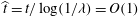 $\widehat{t}=t/\log (1/{\it\lambda})=\mathit{O}(1)$
as
$\widehat{t}=t/\log (1/{\it\lambda})=\mathit{O}(1)$
as
 ${\it\lambda}\rightarrow 0$
. The spatial asymptotic structure is the same as for the time scale of capillary action, though the details in each of the three regions are different, as we shall now describe. We begin with the outer region by expanding
${\it\lambda}\rightarrow 0$
. The spatial asymptotic structure is the same as for the time scale of capillary action, though the details in each of the three regions are different, as we shall now describe. We begin with the outer region by expanding
 $h(r,t)\sim \widehat{h}_{0}(r,\widehat{t}\,)$
and
$h(r,t)\sim \widehat{h}_{0}(r,\widehat{t}\,)$
and
 $s(t)\sim \widehat{s}_{0}(\widehat{t}\,)$
as
$s(t)\sim \widehat{s}_{0}(\widehat{t}\,)$
as
 ${\it\lambda}\rightarrow 0$
to find that the leading-order outer problem is quasi-steady with no mass loss. The solution is the constant-mean-curvature profile
${\it\lambda}\rightarrow 0$
to find that the leading-order outer problem is quasi-steady with no mass loss. The solution is the constant-mean-curvature profile
 $$\begin{eqnarray}\widehat{h}_{0}=\frac{\widehat{{\it\theta}}_{0}}{2\widehat{s}_{0}}(\widehat{s}_{0}^{\,2}-r^{2})\quad \text{for}~0<r<\widehat{s}_{0},\end{eqnarray}$$
where
 $\widehat{{\it\theta}}_{0}(\widehat{t}\,)$
is the leading-order macroscopic contact angle. We note that neither
$\widehat{{\it\theta}}_{0}(\widehat{t}\,)$
is the leading-order macroscopic contact angle. We note that neither
 $\widehat{{\it\theta}}_{0}(\widehat{t}\,)$
nor the leading-order contact-set radius
$\widehat{{\it\theta}}_{0}(\widehat{t}\,)$
nor the leading-order contact-set radius
 $\widehat{s}_{0}(\widehat{t}\,)$
are determined as part of the solution to the leading-order outer problem. The first of the two pieces of information needed to determine these quantities comes from the leading-order version of the global conservation of mass condition (2.16). Matching with the time scale of capillary action tells us that the initial leading-order drop volume is
$\widehat{s}_{0}(\widehat{t}\,)$
are determined as part of the solution to the leading-order outer problem. The first of the two pieces of information needed to determine these quantities comes from the leading-order version of the global conservation of mass condition (2.16). Matching with the time scale of capillary action tells us that the initial leading-order drop volume is
 $V_{\ast }$
. Using the leading-order outer solution (3.18), we find that, since
$V_{\ast }$
. Using the leading-order outer solution (3.18), we find that, since
 ${\it\alpha}=\mathit{O}({\it\lambda}^{1/2})$
as
${\it\alpha}=\mathit{O}({\it\lambda}^{1/2})$
as
 ${\it\lambda}\rightarrow 0$
, the conservation of mass condition (2.16) implies that
${\it\lambda}\rightarrow 0$
, the conservation of mass condition (2.16) implies that
 $$\begin{eqnarray}\frac{{\rm\pi}\widehat{{\it\theta}}_{0}\widehat{s}_{0}^{\,3}}{4}=V_{\ast }.\end{eqnarray}$$
This determines
 $\widehat{{\it\theta}}_{0}$
in terms of
$\widehat{{\it\theta}}_{0}$
in terms of
 $\widehat{s}_{0}$
, leaving us in need of an additional piece of information to determine
$\widehat{s}_{0}$
, leaving us in need of an additional piece of information to determine
 $\widehat{s}_{0}$
. We shall see that this piece of information is the condition for matching the contact angles between the outer and inner regions.
$\widehat{s}_{0}$
. We shall see that this piece of information is the condition for matching the contact angles between the outer and inner regions.
The leading-order inner problem is the same as for the time scale of capillary action, namely (3.7) and (3.9), except that the evaporation rate
 $\mathscr{E}$
appearing on the right-hand side of the thin-film equation (3.7) is replaced by
$\mathscr{E}$
appearing on the right-hand side of the thin-film equation (3.7) is replaced by
 $\mathscr{E}/\widehat{s}_{0}^{\,1/2}$
.
$\mathscr{E}/\widehat{s}_{0}^{\,1/2}$
.
In the intermediate region, we set
 $(s-r)={\it\lambda}^{(1-{\it\xi})}$
and expand
$(s-r)={\it\lambda}^{(1-{\it\xi})}$
and expand
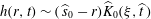 $h(r,t)\sim (\,\widehat{s}_{0}-r)\widehat{K}_{0}({\it\xi},\widehat{t}\,)$
,
$h(r,t)\sim (\,\widehat{s}_{0}-r)\widehat{K}_{0}({\it\xi},\widehat{t}\,)$
,
 $s(t)\sim \widehat{s}_{0}(\widehat{t}\,)$
as
$s(t)\sim \widehat{s}_{0}(\widehat{t}\,)$
as
 ${\it\lambda}\rightarrow 0$
with
${\it\lambda}\rightarrow 0$
with
 ${\it\xi}=\mathit{O}(1)$
,
${\it\xi}=\mathit{O}(1)$
,
 $0<{\it\xi}<1$
. We find that the leading-order mesoscopic contact angle
$0<{\it\xi}<1$
. We find that the leading-order mesoscopic contact angle
 $K_{0}({\it\xi},\widehat{t}\,)$
satisfies (3.14) and (3.15) but with
$K_{0}({\it\xi},\widehat{t}\,)$
satisfies (3.14) and (3.15) but with
 $\text{d}s_{1}/\text{d}t$
and
$\text{d}s_{1}/\text{d}t$
and
 $\mathscr{E}$
replaced by
$\mathscr{E}$
replaced by
 $\text{d}\widehat{s}_{0}/\text{d}t$
and
$\text{d}\widehat{s}_{0}/\text{d}t$
and
 $\mathscr{E}/\widehat{s}_{0}^{\,1/2}$
, respectively. We deduce immediately from the consistency condition for the resulting leading-order intermediate problem the leading-order contact-line law in the form
$\mathscr{E}/\widehat{s}_{0}^{\,1/2}$
, respectively. We deduce immediately from the consistency condition for the resulting leading-order intermediate problem the leading-order contact-line law in the form
 $$\begin{eqnarray}\frac{\text{d}\widehat{s}_{0}}{\text{d}\widehat{t}\,}=\frac{1}{3}\left[\left(\frac{4V_{\ast }}{{\rm\pi}\widehat{s}_{0}^{\,3}}\right)^{3}-{\it\Phi}_{0}\left(\frac{\mathscr{E}}{\widehat{s}_{0}^{\,1/2}},n\right)^{3}\right],\end{eqnarray}$$
where we have substituted for
 $\widehat{{\it\theta}}_{0}$
from the conservation of mass constraint (3.19). Thus, on the time scale of spreading, the effective microscopic contact angle is
$\widehat{{\it\theta}}_{0}$
from the conservation of mass constraint (3.19). Thus, on the time scale of spreading, the effective microscopic contact angle is
 ${\it\Phi}_{0}(\mathscr{E}/\widehat{s}_{0}^{\,1/2},n)$
.
${\it\Phi}_{0}(\mathscr{E}/\widehat{s}_{0}^{\,1/2},n)$
.

Figure 4. (a) The leading-order contact-line law (3.20) on the time scale of spreading for
 $n=1$
,
$n=1$
,
 $V_{\ast }=1$
and values of
$V_{\ast }=1$
and values of
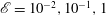 $\mathscr{E}=10^{-2},10^{-1},1$
(solid curves); the dashed curve is Tanner’s law (3.17). We see that the curves all intersect the
$\mathscr{E}=10^{-2},10^{-1},1$
(solid curves); the dashed curve is Tanner’s law (3.17). We see that the curves all intersect the
 $\widehat{s}_{0}$
-axis at a single point, corresponding to the steady state
$\widehat{s}_{0}$
-axis at a single point, corresponding to the steady state
 $\widehat{s}_{0}=s_{e}$
. (b) The leading-order contact-set radius
$\widehat{s}_{0}=s_{e}$
. (b) The leading-order contact-set radius
 $\widehat{s}_{0}$
as a function of time
$\widehat{s}_{0}$
as a function of time
 $\widehat{t}\,$
on the time scale of spreading for
$\widehat{t}\,$
on the time scale of spreading for
 $n=1$
,
$n=1$
,
 $\mathscr{E}=1$
and values of
$\mathscr{E}=1$
and values of
 $V_{\ast }=0.5,1,2,5$
, showing the evolution to the steady state
$V_{\ast }=0.5,1,2,5$
, showing the evolution to the steady state
 $\widehat{s}_{0}=s_{e}$
. (c) Dependence of the steady state
$\widehat{s}_{0}=s_{e}$
. (c) Dependence of the steady state
 $s_{e}$
on the initial drop volume
$s_{e}$
on the initial drop volume
 $V_{\ast }$
for
$V_{\ast }$
for
 $n=1$
and values of
$n=1$
and values of
 $\mathscr{E}=10^{-2},10^{-1},1,10$
(solid curves); the dashed curve is the steady state corresponding to Tanner’s law (3.17). The points marked on the curve for
$\mathscr{E}=10^{-2},10^{-1},1,10$
(solid curves); the dashed curve is the steady state corresponding to Tanner’s law (3.17). The points marked on the curve for
 $\mathscr{E}=1$
correspond to the value of
$\mathscr{E}=1$
correspond to the value of
 $\widehat{s}_{0}(1)$
for the given value of
$\widehat{s}_{0}(1)$
for the given value of
 $V_{\ast }$
, i.e. the points in (b).
$V_{\ast }$
, i.e. the points in (b).
We plot the leading-order contact-line law (3.20) in figure 4(a) for
 $n=1$
,
$n=1$
,
 $V_{\ast }=1$
and several values of
$V_{\ast }=1$
and several values of
 $\mathscr{E}$
. Matching with the time scale of capillary action gives an initial condition
$\mathscr{E}$
. Matching with the time scale of capillary action gives an initial condition
 $\widehat{s}_{0}(0)=1$
. The initial value problem (3.20) subject to
$\widehat{s}_{0}(0)=1$
. The initial value problem (3.20) subject to
 $\widehat{s}_{0}(0)=1$
is solved using matlab’s built-in solver ode113; we use a lookup table and spline interpolation for the function
$\widehat{s}_{0}(0)=1$
is solved using matlab’s built-in solver ode113; we use a lookup table and spline interpolation for the function
 ${\it\Phi}_{0}$
(see appendix B for details of how we compute
${\it\Phi}_{0}$
(see appendix B for details of how we compute
 ${\it\Phi}_{0}$
for given values of
${\it\Phi}_{0}$
for given values of
 $\mathscr{E}$
and
$\mathscr{E}$
and
 $n$
) and check convergence by increasing the number of terms in the lookup table and reducing the error tolerances. The solution of the initial value problem is plotted in figure 4(b) for
$n$
) and check convergence by increasing the number of terms in the lookup table and reducing the error tolerances. The solution of the initial value problem is plotted in figure 4(b) for
 $n=1$
,
$n=1$
,
 $\mathscr{E}=1$
and several values of
$\mathscr{E}=1$
and several values of
 $V_{\ast }$
. We see from these plots that the leading-order contact-set radius evolves to a steady state, with
$V_{\ast }$
. We see from these plots that the leading-order contact-set radius evolves to a steady state, with
 $$\begin{eqnarray}\widehat{s}_{0}(\widehat{t}\,)\rightarrow s_{e}\quad \text{as}~\widehat{t}\,\rightarrow \infty ,\end{eqnarray}$$
and note that both of the cases
 $s_{e}<1$
and
$s_{e}<1$
and
 $s_{e}>1$
are possible: the drop may either spread or retract on this time scale.
$s_{e}>1$
are possible: the drop may either spread or retract on this time scale.
The steady state
 $\widehat{s}_{0}=s_{e}$
must satisfy the equation
$\widehat{s}_{0}=s_{e}$
must satisfy the equation
 $$\begin{eqnarray}V_{\ast }=\frac{{\rm\pi}s_{e}^{3}}{4}{\it\Phi}_{0}\left(\frac{\mathscr{E}}{s_{e}^{1/2}},n\right).\end{eqnarray}$$
From our knowledge of the dependence of
 ${\it\Phi}_{0}$
on its first argument (illustrated by figure 3 and the asymptotes (3.10) and (3.11)), we deduce that
${\it\Phi}_{0}$
on its first argument (illustrated by figure 3 and the asymptotes (3.10) and (3.11)), we deduce that
 $V_{\ast }$
is a continuous, monotone increasing function of
$V_{\ast }$
is a continuous, monotone increasing function of
 $s_{e}$
and thus that there exists a function
$s_{e}$
and thus that there exists a function
 ${\it\Sigma}$
such that
${\it\Sigma}$
such that
 $s_{e}={\it\Sigma}(V_{\ast })$
. A lookup table for the function
$s_{e}={\it\Sigma}(V_{\ast })$
. A lookup table for the function
 ${\it\Sigma}$
, which gives the equilibrium contact-set radius
${\it\Sigma}$
, which gives the equilibrium contact-set radius
 $s_{e}$
for a given initial drop volume
$s_{e}$
for a given initial drop volume
 $V_{\ast }$
, is created by calculating the value of
$V_{\ast }$
, is created by calculating the value of
 $V_{\ast }$
that satisfies (3.22) for several values of
$V_{\ast }$
that satisfies (3.22) for several values of
 $s_{e}$
(using our lookup table for
$s_{e}$
(using our lookup table for
 ${\it\Phi}_{0}$
). A plot of
${\it\Phi}_{0}$
). A plot of
 $s_{e}$
against
$s_{e}$
against
 $V_{\ast }$
for
$V_{\ast }$
for
 $n=1$
and several values of the evaporation rate
$n=1$
and several values of the evaporation rate
 $\mathscr{E}$
is shown in figure 4(c).
$\mathscr{E}$
is shown in figure 4(c).
In summary, on the time scale of spreading
 $\widehat{t}\,=t/\log (1/{\it\lambda})=\mathit{O}(1)$
as
$\widehat{t}\,=t/\log (1/{\it\lambda})=\mathit{O}(1)$
as
 ${\it\lambda}\rightarrow 0$
, mass is conserved to leading order. The leading-order drop profile spreads under surface tension according to a generalization of Tanner’s law that accounts for mass transfer. The drop spreads while maintaining a profile with constant mean curvature (to leading order in the thin-film limit) and ultimately reaches an equilibrium contact-set radius such that the leading-order macroscopic contact angle is equal to the effective microscopic contact angle.
${\it\lambda}\rightarrow 0$
, mass is conserved to leading order. The leading-order drop profile spreads under surface tension according to a generalization of Tanner’s law that accounts for mass transfer. The drop spreads while maintaining a profile with constant mean curvature (to leading order in the thin-film limit) and ultimately reaches an equilibrium contact-set radius such that the leading-order macroscopic contact angle is equal to the effective microscopic contact angle.
We note that for an axisymmetric drop the non-local effects of evaporation on the contact-line law (3.20) manifest themselves in the form of the dependence of the effective microscopic contact angle on the contact-set radius, with the relevant evaporation-induced capillary number, namely
 $\mathscr{E}/\widehat{s}_{0}^{1/2}$
, being proportional to the coefficient of the inverse-square-root singularity in the rate of evaporation at the contact line. If the drop were not axisymmetric but had a smooth contact line, then to leading order the effective microscopic contact angle would vary with distance along the contact line and depend on the liquid flow solely through the geometry of the contact set (since this determines the coefficient of the inverse-square-root singularity in the rate of evaporation at the contact line in each plane perpendicular to the contact line).
$\mathscr{E}/\widehat{s}_{0}^{1/2}$
, being proportional to the coefficient of the inverse-square-root singularity in the rate of evaporation at the contact line. If the drop were not axisymmetric but had a smooth contact line, then to leading order the effective microscopic contact angle would vary with distance along the contact line and depend on the liquid flow solely through the geometry of the contact set (since this determines the coefficient of the inverse-square-root singularity in the rate of evaporation at the contact line in each plane perpendicular to the contact line).
3.4 Time scale of mass loss
The drop starts to lose an order-unity amount of mass on a longer time scale
 $T={\it\alpha}t=\mathit{O}(1)$
as
$T={\it\alpha}t=\mathit{O}(1)$
as
 ${\it\lambda}\rightarrow 0$
. The leading-order outer problem is quasi-steady (as for the spreading time scale) and hence has a constant-mean-curvature solution analogous to (3.18). However, mass loss now enters the global conservation of mass expression at leading order:
${\it\lambda}\rightarrow 0$
. The leading-order outer problem is quasi-steady (as for the spreading time scale) and hence has a constant-mean-curvature solution analogous to (3.18). However, mass loss now enters the global conservation of mass expression at leading order:
 $$\begin{eqnarray}\frac{\text{d}V_{0}}{\text{d}T}=-2{\rm\pi}S_{0};\quad V_{0}=\frac{{\rm\pi}{\it\Theta}_{0}S_{0}^{3}}{4},\end{eqnarray}$$
where
 $V_{0}(T)$
,
$V_{0}(T)$
,
 $S_{0}(T)$
and
$S_{0}(T)$
and
 ${\it\Theta}_{0}(T)$
denote the leading-order drop volume, contact-set radius and macroscopic contact angle respectively. The leading-order inner problem is the same as for the spreading time scale. An intermediate region is not required on this time scale as direct matching of the outer and inner solutions gives
${\it\Theta}_{0}(T)$
denote the leading-order drop volume, contact-set radius and macroscopic contact angle respectively. The leading-order inner problem is the same as for the spreading time scale. An intermediate region is not required on this time scale as direct matching of the outer and inner solutions gives
 $$\begin{eqnarray}{\it\Theta}_{0}={\it\Phi}_{0}\left(\frac{\mathscr{E}}{S_{0}^{1/2}},n\right):\end{eqnarray}$$
the equilibrium established on the time scale of spreading persists throughout the time scale of mass loss. Thus, the problem has been reduced to a single ordinary differential equation for
 $S_{0}$
, namely
$S_{0}$
, namely
 $$\begin{eqnarray}\frac{\text{d}}{\text{d}T}\left[\frac{{\rm\pi}S_{0}^{3}}{4}~{\it\Phi}_{0}\left(\frac{\mathscr{E}}{S_{0}^{1/2}},n\right)\right]=-2{\rm\pi}S_{0}.\end{eqnarray}$$
Matching with the time scale of spreading gives the initial condition
 $$\begin{eqnarray}S_{0}(0)=\lim _{\widehat{t}\,\rightarrow \infty }\widehat{s}_{0}(\widehat{t}\,)=s_{e}={\it\Sigma}(V_{\ast }).\end{eqnarray}$$
We now outline an efficient method to solve numerically the initial value problem (3.25) and (3.26). We note from (3.22), (3.23b
) and (3.24) that
 $S_{0}={\it\Sigma}(V_{0})$
, where
$S_{0}={\it\Sigma}(V_{0})$
, where
 ${\it\Sigma}$
is the same function that relates
${\it\Sigma}$
is the same function that relates
 $s_{e}$
to
$s_{e}$
to
 $V_{\ast }$
. We then deduce from (3.23a
) that the leading-order drop volume
$V_{\ast }$
. We then deduce from (3.23a
) that the leading-order drop volume
 $V_{0}(T)$
at time
$V_{0}(T)$
at time
 $T$
is given by
$T$
is given by
 $$\begin{eqnarray}T=\frac{1}{2{\rm\pi}}\int _{V_{0}(T)}^{V_{\ast }}\frac{\,\text{d}v}{{\it\Sigma}(v)}.\end{eqnarray}$$
In particular, the leading-order extinction time
 $T_{c}$
, such that
$T_{c}$
, such that
 $V_{0}(T_{c})=0$
and
$V_{0}(T_{c})=0$
and
 $t_{c}\sim T_{c}/{\it\alpha}$
as
$t_{c}\sim T_{c}/{\it\alpha}$
as
 ${\it\lambda}\rightarrow 0$
, is given by
${\it\lambda}\rightarrow 0$
, is given by
 $$\begin{eqnarray}T_{c}=\frac{1}{2{\rm\pi}}\int _{0}^{V_{\ast }}\frac{\,\text{d}v}{{\it\Sigma}(v)}.\end{eqnarray}$$
We will analyse the dependence of the extinction time on the parameters in our problem in § 3.7. We determine numerically the evolution of the leading-order contact-set radius and drop volume on the time scale of mass loss as follows. We begin by prescribing a range of values
 $V_{0}\in (0,V_{\ast }]$
. We then evaluate numerically the integral (3.27) to find the corresponding values of
$V_{0}\in (0,V_{\ast }]$
. We then evaluate numerically the integral (3.27) to find the corresponding values of
 $T$
(using a lookup table for
$T$
(using a lookup table for
 ${\it\Sigma}$
, spline interpolation and the function integral in Matlab with sufficiently small error tolerances to resolve the integrable singularity at
${\it\Sigma}$
, spline interpolation and the function integral in Matlab with sufficiently small error tolerances to resolve the integrable singularity at
 $v=0$
). Finally, the relationship
$v=0$
). Finally, the relationship
 $S_{0}={\it\Sigma}(V_{0})$
is used to determine the corresponding values of
$S_{0}={\it\Sigma}(V_{0})$
is used to determine the corresponding values of
 $S_{0}$
.
$S_{0}$
.

Figure 5. (a) The leading-order contact-set radius
 $S_{0}(T)$
as a function of time
$S_{0}(T)$
as a function of time
 $T$
on the mass-loss time scale for
$T$
on the mass-loss time scale for
 $\mathscr{E}=1$
,
$\mathscr{E}=1$
,
 $V_{\ast }=1$
with
$V_{\ast }=1$
with
 $n=1$
(solid curve) and
$n=1$
(solid curve) and
 $n=2$
(dashed curve); we see that the extinction with
$n=2$
(dashed curve); we see that the extinction with
 $n=2$
occurs slightly later. (b) A log–log plot of
$n=2$
occurs slightly later. (b) A log–log plot of
 $S_{0}$
against the time remaining until extinction
$S_{0}$
against the time remaining until extinction
 $(T_{c}-T)$
for
$(T_{c}-T)$
for
 $n=1$
,
$n=1$
,
 $\mathscr{E}=1$
,
$\mathscr{E}=1$
,
 $V_{\ast }=1$
; the solid curve is the numerical solution, obtained as described immediately after (3.28), while the dashed line is the
$V_{\ast }=1$
; the solid curve is the numerical solution, obtained as described immediately after (3.28), while the dashed line is the
 $d^{13/7}$
-law (3.30); we see that a
$d^{13/7}$
-law (3.30); we see that a
 $d^{13/7}$
-law, rather than a
$d^{13/7}$
-law, rather than a
 $d^{2}$
-law, is appropriate.
$d^{2}$
-law, is appropriate.
In figure 5(a), we plot a typical solution for the leading-order contact-set radius
 $S_{0}$
as a function of time
$S_{0}$
as a function of time
 $T$
for
$T$
for
 $n=1$
and
$n=1$
and
 $n=2$
and see that the extinction time for
$n=2$
and see that the extinction time for
 $n=2$
is slightly larger than the extinction time for
$n=2$
is slightly larger than the extinction time for
 $n=1$
. An explanation for this is as follows: the dependence of the mobility on
$n=1$
. An explanation for this is as follows: the dependence of the mobility on
 $n$
in the leading-order inner thin-film equation (3.7) means that the effective microscopic contact angle is larger for
$n$
in the leading-order inner thin-film equation (3.7) means that the effective microscopic contact angle is larger for
 $n=2$
than for
$n=2$
than for
 $n=1$
(as illustrated in figure 3
a). On the time scale of mass loss, the macroscopic and effective microscopic contact angles are equal so that to achieve a given drop volume, the contact-set radius must be smaller for
$n=1$
(as illustrated in figure 3
a). On the time scale of mass loss, the macroscopic and effective microscopic contact angles are equal so that to achieve a given drop volume, the contact-set radius must be smaller for
 $n=2$
than for
$n=2$
than for
 $n=1$
to compensate for the larger macroscopic contact angle. Since the global evaporation rate is proportional to the contact-set radius, this means that the evaporation rate for a given drop volume is smaller for
$n=1$
to compensate for the larger macroscopic contact angle. Since the global evaporation rate is proportional to the contact-set radius, this means that the evaporation rate for a given drop volume is smaller for
 $n=2$
than for
$n=2$
than for
 $n=1$
, resulting in a larger extinction time for
$n=1$
, resulting in a larger extinction time for
 $n=2$
. Since the evolution for
$n=2$
. Since the evolution for
 $n=1$
and
$n=1$
and
 $n=2$
is otherwise qualitatively similar, we shall hereafter focus on the case
$n=2$
is otherwise qualitatively similar, we shall hereafter focus on the case
 $n=1$
(for which it is easier to carry out numerical simulations of the full problem for reasons given in appendix A).
$n=1$
(for which it is easier to carry out numerical simulations of the full problem for reasons given in appendix A).
Close to extinction, the leading-order contact-set radius
 $S_{0}\rightarrow 0^{+}$
. Hence,
$S_{0}\rightarrow 0^{+}$
. Hence,
 $\mathscr{E}/S_{0}^{1/2}\rightarrow \infty$
and we deduce from the asymptote (3.11) for
$\mathscr{E}/S_{0}^{1/2}\rightarrow \infty$
and we deduce from the asymptote (3.11) for
 ${\it\Phi}_{0}$
that
${\it\Phi}_{0}$
that
 $$\begin{eqnarray}{\it\Phi}_{0}\left(\frac{\mathscr{E}}{S_{0}^{1/2}},n\right)\sim \frac{{\it\Phi}_{\infty }(n)\mathscr{E}^{2/7}}{S_{0}^{1/7}}\quad \text{as}~S_{0}\rightarrow 0^{+}.\end{eqnarray}$$
We note that the effective microscopic contact angle, and thus also the macroscopic contact angle, is unbounded as
 $T\rightarrow T_{c}^{-}$
, and therefore that the lubrication approximation breaks down when
$T\rightarrow T_{c}^{-}$
, and therefore that the lubrication approximation breaks down when
 $S_{0}=\mathit{O}({\it\Psi}^{7})$
as
$S_{0}=\mathit{O}({\it\Psi}^{7})$
as
 ${\it\Psi}\rightarrow 0$
. Since
${\it\Psi}\rightarrow 0$
. Since
 ${\it\Psi}^{7}\ll {\it\lambda}$
for the values given in table 2 and its caption, in practice we expect the small-slip asymptotics to break down before the lubrication approximation does, but we do not discuss further in this paper the details of the breakdown.
${\it\Psi}^{7}\ll {\it\lambda}$
for the values given in table 2 and its caption, in practice we expect the small-slip asymptotics to break down before the lubrication approximation does, but we do not discuss further in this paper the details of the breakdown.
We deduce from the evolution equation (3.25) and the asymptote (3.29) that
 $$\begin{eqnarray}S_{0}\sim A(T_{c}-T)^{7/13}\quad \text{as}~T\rightarrow T_{c}^{-},\end{eqnarray}$$
where the coefficient
 $A$
is given in terms of
$A$
is given in terms of
 ${\it\Phi}_{\infty }(n)$
and
${\it\Phi}_{\infty }(n)$
and
 $\mathscr{E}$
by
$\mathscr{E}$
by
 $$\begin{eqnarray}A=\left(\frac{26}{5{\it\Phi}_{\infty }(n)}\right)^{7/13}\mathscr{E}^{-2/13},\end{eqnarray}$$
and
 $T_{c}$
is given by (3.28). Equation (3.30) is our main result: rather than the
$T_{c}$
is given by (3.28). Equation (3.30) is our main result: rather than the
 $d^{2}$
-law, a (slightly modified) ‘
$d^{2}$
-law, a (slightly modified) ‘
 $d^{13/7}$
-law’ is appropriate in the distinguished limit
$d^{13/7}$
-law’ is appropriate in the distinguished limit
 $\mathscr{E}=\mathit{O}(1)$
as
$\mathscr{E}=\mathit{O}(1)$
as
 ${\it\lambda}\rightarrow 0$
. We plot the numerical solution of the initial value problem (3.25) and (3.26), together with the near-extinction asymptote (3.30), in figure 5(b); this clearly demonstrates a
${\it\lambda}\rightarrow 0$
. We plot the numerical solution of the initial value problem (3.25) and (3.26), together with the near-extinction asymptote (3.30), in figure 5(b); this clearly demonstrates a
 $d^{13/7}$
-law.
$d^{13/7}$
-law.
In summary, on the time scale of mass loss
 $T={\it\alpha}t=\mathit{O}(1)$
as
$T={\it\alpha}t=\mathit{O}(1)$
as
 ${\it\lambda}\rightarrow 0$
, the drop starts to lose an order-unity amount of mass. The leading-order drop profile has constant mean curvature (to leading order in the thin-film limit), as on the time scale of spreading, and the leading-order macroscopic contact angle is equal to the effective microscopic contact angle throughout the mass-loss time scale. The contact line recedes from the equilibrium position it reached on the time scale of spreading until the drop becomes extinct at some finite time. Close to extinction, the leading-order contact-set radius evolves as the time remaining until extinction raised to the power 7/13: a
${\it\lambda}\rightarrow 0$
, the drop starts to lose an order-unity amount of mass. The leading-order drop profile has constant mean curvature (to leading order in the thin-film limit), as on the time scale of spreading, and the leading-order macroscopic contact angle is equal to the effective microscopic contact angle throughout the mass-loss time scale. The contact line recedes from the equilibrium position it reached on the time scale of spreading until the drop becomes extinct at some finite time. Close to extinction, the leading-order contact-set radius evolves as the time remaining until extinction raised to the power 7/13: a
 $d^{13/7}$
-law. The
$d^{13/7}$
-law. The
 $d^{2}$
-law is not valid in the distinguished limit in which
$d^{2}$
-law is not valid in the distinguished limit in which
 $\mathscr{E}=\mathit{O}(1)$
as
$\mathscr{E}=\mathit{O}(1)$
as
 ${\it\lambda}\rightarrow 0$
, although we note that the
${\it\lambda}\rightarrow 0$
, although we note that the
 $d^{13/7}$
-law is only a slight modification.
$d^{13/7}$
-law is only a slight modification.
3.5 Small-
 $\mathscr{E}$
sub-limit
$\mathscr{E}$
sub-limit

The analysis of §§ 3.2–3.4 pertains to the distinguished limit in which
 $\mathscr{E}=\mathit{O}(1)$
as
$\mathscr{E}=\mathit{O}(1)$
as
 ${\it\lambda}\rightarrow 0$
. We saw that the
${\it\lambda}\rightarrow 0$
. We saw that the
 $d^{2}$
-law was not valid in this limit. We now consider the sub-limit
$d^{2}$
-law was not valid in this limit. We now consider the sub-limit
 $\mathscr{E}\rightarrow 0$
as
$\mathscr{E}\rightarrow 0$
as
 ${\it\lambda}\rightarrow 0$
. In this case the time scale of spreading is sufficiently small compared to the time scale of mass loss that the effects of evaporation do not enter the inner region to leading order. In § 1, we argued physically that in this case we should expect the
${\it\lambda}\rightarrow 0$
. In this case the time scale of spreading is sufficiently small compared to the time scale of mass loss that the effects of evaporation do not enter the inner region to leading order. In § 1, we argued physically that in this case we should expect the
 $d^{2}$
-law to be valid. We now show that this result is recovered from the distinguished limit in which
$d^{2}$
-law to be valid. We now show that this result is recovered from the distinguished limit in which
 $\mathscr{E}=\mathit{O}(1)$
as
$\mathscr{E}=\mathit{O}(1)$
as
 ${\it\lambda}\rightarrow 0$
.
${\it\lambda}\rightarrow 0$
.
From the asymptote (3.10) for
 ${\it\Phi}_{0}$
, we have that
${\it\Phi}_{0}$
, we have that
 $$\begin{eqnarray}{\it\Phi}_{0}\left(\frac{\mathscr{E}}{\widehat{s}_{0}^{\,1/2}},n\right)\sim 1\quad \text{as}~\mathscr{E}\rightarrow 0~\text{with}~\mathscr{E}\ll \widehat{s}_{0}^{\,1/2}.\end{eqnarray}$$
Since
 $\widehat{s}_{0}=\mathit{O}(1)$
on the time scale of spreading, (3.32) tells us that the time scale of capillary action and the time scale of spreading for this sub-limit are identical to those for the distinguished limit in which
$\widehat{s}_{0}=\mathit{O}(1)$
on the time scale of spreading, (3.32) tells us that the time scale of capillary action and the time scale of spreading for this sub-limit are identical to those for the distinguished limit in which
 $\mathscr{E}=\mathit{O}(1)$
as
$\mathscr{E}=\mathit{O}(1)$
as
 ${\it\lambda}\rightarrow 0$
, but with the effective microscopic contact angle
${\it\lambda}\rightarrow 0$
, but with the effective microscopic contact angle
 ${\it\Phi}_{0}$
replaced by the true microscopic contact angle, namely 1. Hence, the contact-line law for the time scale of spreading is now precisely Tanner’s law (3.17). We may solve exactly the leading-order version of (3.22) for the steady state attained on the time scale of spreading to give
${\it\Phi}_{0}$
replaced by the true microscopic contact angle, namely 1. Hence, the contact-line law for the time scale of spreading is now precisely Tanner’s law (3.17). We may solve exactly the leading-order version of (3.22) for the steady state attained on the time scale of spreading to give
 $$\begin{eqnarray}s_{e}\sim \left(\frac{4V_{\ast }}{{\rm\pi}}\right)^{1/3}\quad \text{as}~\mathscr{E}\rightarrow 0.\end{eqnarray}$$
On the time scale of mass loss, we begin with
 $S_{0}=\mathit{O}(1)$
and may therefore use the asymptote (3.32) for
$S_{0}=\mathit{O}(1)$
and may therefore use the asymptote (3.32) for
 ${\it\Phi}_{0}$
. However, we note that the analysis will break down when
${\it\Phi}_{0}$
. However, we note that the analysis will break down when
 $S_{0}=\mathit{O}(\mathscr{E}^{2})$
, at which point the assumption that
$S_{0}=\mathit{O}(\mathscr{E}^{2})$
, at which point the assumption that
 $\mathscr{E}/S_{0}^{1/2}\ll 1$
becomes invalid. While this assumption remains valid, the matching condition between the outer and inner regions (3.24) implies that the drop evolves with a constant macroscopic contact angle equal to its microscopic value, i.e.
$\mathscr{E}/S_{0}^{1/2}\ll 1$
becomes invalid. While this assumption remains valid, the matching condition between the outer and inner regions (3.24) implies that the drop evolves with a constant macroscopic contact angle equal to its microscopic value, i.e.
 ${\it\Theta}_{0}(T)\equiv 1$
. The leading-order version of the initial value problem (3.25) and (3.26) for the drop radius may then be solved exactly to give
${\it\Theta}_{0}(T)\equiv 1$
. The leading-order version of the initial value problem (3.25) and (3.26) for the drop radius may then be solved exactly to give
 $$\begin{eqnarray}S_{0}(T)\sim A_{0}(T_{c0}-T)^{1/2}\quad \text{as}~\mathscr{E}\rightarrow 0,\quad A_{0}=\frac{4}{\sqrt{3}},\quad T_{c0}=\frac{3}{16}\left(\frac{4V_{\ast }}{{\rm\pi}}\right)^{2/3}.\end{eqnarray}$$
We therefore do indeed recover the
 $d^{2}$
-law in the limit
$d^{2}$
-law in the limit
 $\mathscr{E}\rightarrow 0$
as
$\mathscr{E}\rightarrow 0$
as
 ${\it\lambda}\rightarrow 0$
. Moreover, this behaviour is valid for the entire mass-loss time scale and not just close to extinction.
${\it\lambda}\rightarrow 0$
. Moreover, this behaviour is valid for the entire mass-loss time scale and not just close to extinction.
The leading-order solution (3.34) implies that the assumption that
 $\mathscr{E}/S_{0}^{1/2}\ll 1$
becomes invalid on the time scale
$\mathscr{E}/S_{0}^{1/2}\ll 1$
becomes invalid on the time scale
 $\overline{T}=(T-T_{c0})/\mathscr{E}^{4}=\mathit{O}(1)$
as
$\overline{T}=(T-T_{c0})/\mathscr{E}^{4}=\mathit{O}(1)$
as
 $\mathscr{E}\rightarrow 0$
, before the drop is extinct. To examine the near-extinction evolution on this time scale, we use the solution (3.34) to motivate scaling
$\mathscr{E}\rightarrow 0$
, before the drop is extinct. To examine the near-extinction evolution on this time scale, we use the solution (3.34) to motivate scaling
 $r$
,
$r$
,
 $s$
and
$s$
and
 $h$
with
$h$
with
 $\mathscr{E}^{2}$
both in the thin-film equation given by (2.11) and (2.12) and in the boundary conditions (2.14), but on the time scale of mass loss (so that
$\mathscr{E}^{2}$
both in the thin-film equation given by (2.11) and (2.12) and in the boundary conditions (2.14), but on the time scale of mass loss (so that
 $\partial h/\partial t$
is replaced by
$\partial h/\partial t$
is replaced by
 ${\it\alpha}\,\partial h/\partial T$
in (2.11)). We find that the resulting versions of (2.11), (2.12) and (2.14) are unchanged upon replacing
${\it\alpha}\,\partial h/\partial T$
in (2.11)). We find that the resulting versions of (2.11), (2.12) and (2.14) are unchanged upon replacing
 ${\it\alpha}$
and
${\it\alpha}$
and
 ${\it\lambda}$
with
${\it\lambda}$
with
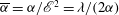 $\overline{{\it\alpha}}={\it\alpha}/\mathscr{E}^{2}={\it\lambda}/(2{\it\alpha})$
and
$\overline{{\it\alpha}}={\it\alpha}/\mathscr{E}^{2}={\it\lambda}/(2{\it\alpha})$
and
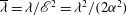 $\overline{{\it\lambda}}={\it\lambda}/\mathscr{E}^{2}={\it\lambda}^{2}/(2{\it\alpha}^{2})$
, respectively. Hence, if
$\overline{{\it\lambda}}={\it\lambda}/\mathscr{E}^{2}={\it\lambda}^{2}/(2{\it\alpha}^{2})$
, respectively. Hence, if
 ${\it\lambda}\ll {\it\alpha}$
as
${\it\lambda}\ll {\it\alpha}$
as
 ${\it\lambda}\rightarrow 0$
(in addition to the assumption that
${\it\lambda}\rightarrow 0$
(in addition to the assumption that
 ${\it\alpha}\ll {\it\lambda}^{1/2}$
as
${\it\alpha}\ll {\it\lambda}^{1/2}$
as
 ${\it\lambda}\rightarrow 0$
, corresponding to being in the small-
${\it\lambda}\rightarrow 0$
, corresponding to being in the small-
 $\mathscr{E}$
regime), then
$\mathscr{E}$
regime), then
 $\overline{{\it\alpha}}\ll 1$
and
$\overline{{\it\alpha}}\ll 1$
and
 $\overline{{\it\lambda}}\ll 1$
, and we deduce immediately that the asymptotic analysis in § 3.4 pertains: the evolution of the contact-set radius
$\overline{{\it\lambda}}\ll 1$
, and we deduce immediately that the asymptotic analysis in § 3.4 pertains: the evolution of the contact-set radius
 $\overline{S}(\overline{T}\,)=S(T)/\mathscr{E}^{2}$
is governed to leading order by (3.25) but with
$\overline{S}(\overline{T}\,)=S(T)/\mathscr{E}^{2}$
is governed to leading order by (3.25) but with
 $S_{0}$
,
$S_{0}$
,
 $T$
and
$T$
and
 $\mathscr{E}$
replaced by
$\mathscr{E}$
replaced by
 $\overline{S}_{0}$
,
$\overline{S}_{0}$
,
 $\overline{T}$
and
$\overline{T}$
and
 $\overline{\mathscr{E}}=(2/\overline{{\it\lambda}})^{1/2}\overline{{\it\alpha}}=1$
, respectively (thus, this regime corresponds to the dimensional contact-set radius
$\overline{\mathscr{E}}=(2/\overline{{\it\lambda}})^{1/2}\overline{{\it\alpha}}=1$
, respectively (thus, this regime corresponds to the dimensional contact-set radius
 $s^{\ast }$
being comparable to
$s^{\ast }$
being comparable to
 $R_{crit}$
). Matching with the leading-order solution (3.34) on the time scale of mass loss then yields the matching condition that
$R_{crit}$
). Matching with the leading-order solution (3.34) on the time scale of mass loss then yields the matching condition that
 $\overline{S}_{0}(\overline{T}\,)\sim A_{0}(-\overline{T}\,)^{1/2}$
as
$\overline{S}_{0}(\overline{T}\,)\sim A_{0}(-\overline{T}\,)^{1/2}$
as
 $\overline{T}\rightarrow -\infty$
. Thus, in the regime in which
$\overline{T}\rightarrow -\infty$
. Thus, in the regime in which
 ${\it\lambda}\ll {\it\alpha}\ll {\it\lambda}^{1/2}$
as
${\it\lambda}\ll {\it\alpha}\ll {\it\lambda}^{1/2}$
as
 ${\it\lambda}\rightarrow 0$
, a
${\it\lambda}\rightarrow 0$
, a
 $d^{13/7}$
-law is appropriate close to extinction. We note that if
$d^{13/7}$
-law is appropriate close to extinction. We note that if
 ${\it\alpha}=\mathit{O}({\it\lambda})$
as
${\it\alpha}=\mathit{O}({\it\lambda})$
as
 ${\it\lambda}\rightarrow 0$
, then the evolution close to extinction is instead governed by the full balance of terms in (2.11) and (2.12), a regime that we do not consider further in this paper.
${\it\lambda}\rightarrow 0$
, then the evolution close to extinction is instead governed by the full balance of terms in (2.11) and (2.12), a regime that we do not consider further in this paper.
In summary, if the ratio
 ${\it\alpha}$
of the time scales of capillary action and mass loss satisfies the condition
${\it\alpha}$
of the time scales of capillary action and mass loss satisfies the condition
 $$\begin{eqnarray}{\it\lambda}\ll {\it\alpha}\ll {\it\lambda}^{1/2}\quad \text{as}~{\it\lambda}\rightarrow 0,\end{eqnarray}$$
then the
 $d^{2}$
-law is valid for the whole time scale of mass loss, except in a small temporal boundary layer close to extinction where a
$d^{2}$
-law is valid for the whole time scale of mass loss, except in a small temporal boundary layer close to extinction where a
 $d^{13/7}$
-law should instead hold close to extinction. However, once
$d^{13/7}$
-law should instead hold close to extinction. However, once
 ${\it\alpha}$
is large enough that
${\it\alpha}$
is large enough that
 $\mathscr{E}=\mathit{O}(1)$
as
$\mathscr{E}=\mathit{O}(1)$
as
 ${\it\lambda}\rightarrow 0$
, our analysis predicts that the scaling behaviour changes and instead a
${\it\lambda}\rightarrow 0$
, our analysis predicts that the scaling behaviour changes and instead a
 $d^{13/7}$
-law is appropriate close to extinction on the time scale of mass loss. We note that our numerical simulations in fact suggest this law to be valid to a good approximation for the whole mass-loss time scale. A possible explanation for this extended validity of the
$d^{13/7}$
-law is appropriate close to extinction on the time scale of mass loss. We note that our numerical simulations in fact suggest this law to be valid to a good approximation for the whole mass-loss time scale. A possible explanation for this extended validity of the
 $d^{13/7}$
-law may be the following. We recall that the
$d^{13/7}$
-law may be the following. We recall that the
 $d^{13/7}$
-law came from the fact that, close to extinction,
$d^{13/7}$
-law came from the fact that, close to extinction,
 ${\it\Phi}_{0}$
could be replaced by its large-argument asymptote (3.11). Now consider the approximation (3.12) to
${\it\Phi}_{0}$
could be replaced by its large-argument asymptote (3.11). Now consider the approximation (3.12) to
 ${\it\Phi}_{0}$
; since
${\it\Phi}_{0}$
; since
 ${\it\Phi}_{\infty }(n)^{7/2}$
is (moderately) large (at least for
${\it\Phi}_{\infty }(n)^{7/2}$
is (moderately) large (at least for
 $n=1$
and
$n=1$
and
 $n=2$
), the approximation (3.12) may itself be approximated by
$n=2$
), the approximation (3.12) may itself be approximated by
 ${\it\Phi}_{\infty }(n)\mathscr{E}^{2/7}$
. This suggests that the asymptote (3.11) is a good approximation to
${\it\Phi}_{\infty }(n)\mathscr{E}^{2/7}$
. This suggests that the asymptote (3.11) is a good approximation to
 ${\it\Phi}_{0}(\mathscr{E},n)$
even for order-unity values of
${\it\Phi}_{0}(\mathscr{E},n)$
even for order-unity values of
 $\mathscr{E}$
, and consequently we do not need to be especially close to extinction for the
$\mathscr{E}$
, and consequently we do not need to be especially close to extinction for the
 $d^{13/7}$
-law to be valid. Finally, we note that if
$d^{13/7}$
-law to be valid. Finally, we note that if
 ${\it\alpha}$
were sufficiently large that evaporation entered the outer or intermediate region at leading order, the behaviour would change yet again, but we do not consider further these apparently physically unrealistic regimes.
${\it\alpha}$
were sufficiently large that evaporation entered the outer or intermediate region at leading order, the behaviour would change yet again, but we do not consider further these apparently physically unrealistic regimes.
3.6 Comparison to numerical results
In order to validate our asymptotic results, we solve numerically the full problem (2.11)–(2.15) using a finite-element method. A description of the method used is given in appendix A; we note in particular that the initial condition used for the simulations (3.6) is not close to that of a parabola and that we found it easier to use
 $n=1$
, rather than
$n=1$
, rather than
 $n=2$
, in our simulations, so that the pressure is not unbounded at the contact line.
$n=2$
, in our simulations, so that the pressure is not unbounded at the contact line.
We use our leading-order asymptotic results to construct additive composite expansions for the leading-order contact-set radius and leading-order drop volume across the three time scales. Since the leading-order drop volume is constant on the time scales of capillary action and spreading, the leading-order composite expansion for the drop volume is simply given by
 $V_{0}(T)$
. The leading-order contact-set radius is constant on the time scale of capillary action, so the leading-order composite expansion is obtained by adding together the solutions
$V_{0}(T)$
. The leading-order contact-set radius is constant on the time scale of capillary action, so the leading-order composite expansion is obtained by adding together the solutions
 $\widehat{s}_{0}$
and
$\widehat{s}_{0}$
and
 $S_{0}$
on the time scales of spreading and mass loss and then subtracting the ‘overlap’
$S_{0}$
on the time scales of spreading and mass loss and then subtracting the ‘overlap’
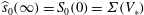 $\widehat{s}_{0}(\infty )=S_{0}(0)={\it\Sigma}(V_{\ast })$
.
$\widehat{s}_{0}(\infty )=S_{0}(0)={\it\Sigma}(V_{\ast })$
.

Figure 6. Comparison of our leading-order asymptotic predictions with the full numerical solutions with
 $n=1$
,
$n=1$
,
 $V_{\ast }=1$
,
$V_{\ast }=1$
,
 ${\it\lambda}=10^{-4}$
and values of
${\it\lambda}=10^{-4}$
and values of
 ${\it\alpha}$
chosen such that
${\it\alpha}$
chosen such that
 $\mathscr{E}=10^{-2},10^{-1},1,10$
. In (a), we plot the contact-set radius
$\mathscr{E}=10^{-2},10^{-1},1,10$
. In (a), we plot the contact-set radius
 $s$
as a function of time
$s$
as a function of time
 $t$
. In (b), we plot the drop volume
$t$
. In (b), we plot the drop volume
 $V$
as a function of time
$V$
as a function of time
 $t$
. The solid curves show the full numerical solutions and the dashed curves show the leading-order asymptotic solutions (which are obtained from an additive composite expansion over the three time scales, as described in the text); we see good agreement between the two methods. In (c) and (d), we plot
$t$
. The solid curves show the full numerical solutions and the dashed curves show the leading-order asymptotic solutions (which are obtained from an additive composite expansion over the three time scales, as described in the text); we see good agreement between the two methods. In (c) and (d), we plot
 $s^{13/7}$
and
$s^{13/7}$
and
 $V^{13/20}$
, respectively, as functions of the time remaining until extinction
$V^{13/20}$
, respectively, as functions of the time remaining until extinction
 $(t_{c}-t)$
. For the leading-order asymptotic solutions, the extinction time is computed via (3.28). All the curves look like straight lines through the origin close to extinction, which suggests that the
$(t_{c}-t)$
. For the leading-order asymptotic solutions, the extinction time is computed via (3.28). All the curves look like straight lines through the origin close to extinction, which suggests that the
 $d^{13/7}$
-law is valid close to extinction (if a
$d^{13/7}$
-law is valid close to extinction (if a
 $d^{2}$
-law were valid, the solutions would show a noticeable curve).
$d^{2}$
-law were valid, the solutions would show a noticeable curve).
The contact-set radius and drop volume as calculated by the full numerical solutions and the leading-order asymptotics are compared in figure 6(a,b) for
 $n=1$
,
$n=1$
,
 $V_{\ast }=1$
and several values of
$V_{\ast }=1$
and several values of
 $\mathscr{E}$
. The plots show good agreement between the numerics and asymptotics, particularly for smaller values of
$\mathscr{E}$
. The plots show good agreement between the numerics and asymptotics, particularly for smaller values of
 $\mathscr{E}$
. We can also see from these plots the presence of three distinct time scales in the evolution. Initially, there is a fast time scale on which the contact-set radius and drop volume are both constant. We then move to a longer time scale during which the drop volume remains constant but the contact-set radius begins to evolve: the contact line advances for smaller values of
$\mathscr{E}$
. We can also see from these plots the presence of three distinct time scales in the evolution. Initially, there is a fast time scale on which the contact-set radius and drop volume are both constant. We then move to a longer time scale during which the drop volume remains constant but the contact-set radius begins to evolve: the contact line advances for smaller values of
 $\mathscr{E}$
and recedes for larger values of
$\mathscr{E}$
and recedes for larger values of
 $\mathscr{E}$
. Physically, the drop is equilibrating under surface tension such that its macroscopic contact angle is equal to the effective microscopic contact angle (which depends on
$\mathscr{E}$
. Physically, the drop is equilibrating under surface tension such that its macroscopic contact angle is equal to the effective microscopic contact angle (which depends on
 $\mathscr{E}$
), and the contact-set radius adjusts to preserve volume. Finally, there is an even longer time scale on which both the contact-set radius and drop volume decrease monotonically with time until some finite time at which they both vanish. These three time scales correspond to the time scales of capillary action, spreading and mass loss that we identified as part of our asymptotic analysis.
$\mathscr{E}$
), and the contact-set radius adjusts to preserve volume. Finally, there is an even longer time scale on which both the contact-set radius and drop volume decrease monotonically with time until some finite time at which they both vanish. These three time scales correspond to the time scales of capillary action, spreading and mass loss that we identified as part of our asymptotic analysis.
From (3.23b
), (3.24), (3.29) and (3.30), we deduce that
 $V_{0}\sim B(T_{c}-T)^{13/20}$
as
$V_{0}\sim B(T_{c}-T)^{13/20}$
as
 $T\rightarrow T_{c}^{-}$
, for some constant
$T\rightarrow T_{c}^{-}$
, for some constant
 $B$
. Thus, the
$B$
. Thus, the
 $d^{13/7}$
-law has a corresponding
$d^{13/7}$
-law has a corresponding
 $V^{13/20}$
-law that states that, close to extinction, the time remaining until extinction is proportional to the drop volume raised to the power 13/20. In figure 6(c,d), we plot
$V^{13/20}$
-law that states that, close to extinction, the time remaining until extinction is proportional to the drop volume raised to the power 13/20. In figure 6(c,d), we plot
 $s^{13/7}$
and
$s^{13/7}$
and
 $V^{13/20}$
, respectively, as functions of the time remaining until extinction. We see that both the full numerical solutions and the leading-order asymptotic solutions look like straight lines through the origin close to extinction, which supports the claim that a
$V^{13/20}$
, respectively, as functions of the time remaining until extinction. We see that both the full numerical solutions and the leading-order asymptotic solutions look like straight lines through the origin close to extinction, which supports the claim that a
 $d^{13/7}$
-law is valid close to extinction.
$d^{13/7}$
-law is valid close to extinction.

Figure 7. (a) The extinction time
 $t_{c}\sim T_{c}/{\it\alpha}$
as a function of the parameter
$t_{c}\sim T_{c}/{\it\alpha}$
as a function of the parameter
 ${\it\alpha}$
calculated using the expression (3.28) for
${\it\alpha}$
calculated using the expression (3.28) for
 $n=1$
,
$n=1$
,
 ${\it\lambda}=10^{-4}$
and values of
${\it\lambda}=10^{-4}$
and values of
 $V_{\ast }=0.1,1,10$
. The points plotted on the curve for
$V_{\ast }=0.1,1,10$
. The points plotted on the curve for
 $V_{\ast }=1$
are values of
$V_{\ast }=1$
are values of
 $t_{c}$
calculated using the finite-element method; we see that these values give good agreement with the results of the reduced problem obtained using (3.28). (b)
$t_{c}$
calculated using the finite-element method; we see that these values give good agreement with the results of the reduced problem obtained using (3.28). (b)
 $T_{c}$
as a function of the initial drop volume
$T_{c}$
as a function of the initial drop volume
 $V_{\ast }$
for
$V_{\ast }$
for
 $n=1$
and values of
$n=1$
and values of
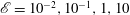 $\mathscr{E}=10^{-2},10^{-1},1,10$
(solid curves). The dashed curve is the small-
$\mathscr{E}=10^{-2},10^{-1},1,10$
(solid curves). The dashed curve is the small-
 $\mathscr{E}$
asymptote. (c) The relative error in
$\mathscr{E}$
asymptote. (c) The relative error in
 $T_{c}$
introduced by assuming that the effective microscopic contact angle is equal to unity, as a function of
$T_{c}$
introduced by assuming that the effective microscopic contact angle is equal to unity, as a function of
 $\mathscr{E}$
for
$\mathscr{E}$
for
 $n=1$
and values of
$n=1$
and values of
 $V_{\ast }=0.1,1,10$
.
$V_{\ast }=0.1,1,10$
.
The extinction times calculated from the full numerical solutions are plotted as functions of
 ${\it\alpha}$
in figure 7(a) (points), together with the dependence of
${\it\alpha}$
in figure 7(a) (points), together with the dependence of
 $t_{c}$
on
$t_{c}$
on
 ${\it\alpha}$
predicted by the leading-order asymptotics (about which more shortly). Once again we see excellent agreement between the two methods.
${\it\alpha}$
predicted by the leading-order asymptotics (about which more shortly). Once again we see excellent agreement between the two methods.
The agreement that we have found between our leading-order asymptotic predictions and the solution as calculated by the finite-element method gives us confidence that our asymptotic results are correct.
3.7 Extinction time
We shall now investigate the dependence of the extinction time
 $t_{c}$
on the initial drop volume
$t_{c}$
on the initial drop volume
 $V_{\ast }$
and the ratio
$V_{\ast }$
and the ratio
 ${\it\alpha}$
of the time scales of capillary action and mass loss (we shall take the slip exponent
${\it\alpha}$
of the time scales of capillary action and mass loss (we shall take the slip exponent
 $n$
to be equal to 1 for the reasons given in § 3.4). We shall then put our results into context by comparing them with the case in which the effective microscopic contact angle is assumed to be constant.
$n$
to be equal to 1 for the reasons given in § 3.4). We shall then put our results into context by comparing them with the case in which the effective microscopic contact angle is assumed to be constant.
We exploit the fact that our asymptotic analysis has essentially reduced the problem to a single ordinary differential equation to efficiently perform a parameter sweep of the extinction time
 $t_{c}$
. We plot
$t_{c}$
. We plot
 $t_{c}$
as a function of the ratio
$t_{c}$
as a function of the ratio
 ${\it\alpha}$
of the time scales of capillary action and mass loss in figure 7(a) for
${\it\alpha}$
of the time scales of capillary action and mass loss in figure 7(a) for
 $n=1$
and several values of
$n=1$
and several values of
 $V_{\ast }$
. We observe that
$V_{\ast }$
. We observe that
 $t_{c}$
is an increasing function of the initial drop volume
$t_{c}$
is an increasing function of the initial drop volume
 $V_{\ast }$
, in line with our physical intuition. We also observe that
$V_{\ast }$
, in line with our physical intuition. We also observe that
 $t_{c}$
is a decreasing function of
$t_{c}$
is a decreasing function of
 ${\it\alpha}$
, which also makes physical sense since
${\it\alpha}$
, which also makes physical sense since
 ${\it\alpha}$
is inversely proportional to the typical time scale of mass loss
${\it\alpha}$
is inversely proportional to the typical time scale of mass loss
 ${\it\tau}_{M}$
.
${\it\tau}_{M}$
.
Now let us put these results into context by considering the case in which the effective microscopic angle is assumed to be equal to unity. This assumption has been made in the literature when considering a ‘constant contact angle mode’ for the evaporation of a drop (see, for example, Erbil et al.
Reference Erbil, McHale and Newton2002; Hu & Larson Reference Hu and Larson2002; Stauber et al.
Reference Stauber, Wilson, Duffy and Sefiane2014). We saw in § 3.5 that this assumption should be valid when the evaporation rate
 $\mathscr{E}$
is small and found an exact expression (3.34c
) for the quantity
$\mathscr{E}$
is small and found an exact expression (3.34c
) for the quantity
 $T_{c0}$
such that
$T_{c0}$
such that
 $t_{c}\sim T_{c0}/{\it\alpha}$
as
$t_{c}\sim T_{c0}/{\it\alpha}$
as
 ${\it\lambda},~\mathscr{E}\rightarrow 0$
. In figure 7(b), we plot
${\it\lambda},~\mathscr{E}\rightarrow 0$
. In figure 7(b), we plot
 $T_{c}$
as a function of the initial drop volume
$T_{c}$
as a function of the initial drop volume
 $V_{\ast }$
for several values of
$V_{\ast }$
for several values of
 $\mathscr{E}$
, together with the small-
$\mathscr{E}$
, together with the small-
 $\mathscr{E}$
asymptote. We observe that the difference between the small-
$\mathscr{E}$
asymptote. We observe that the difference between the small-
 $\mathscr{E}$
asymptote (3.34c
) and the expression (3.28) for
$\mathscr{E}$
asymptote (3.34c
) and the expression (3.28) for
 $T_{c}$
is significant for
$T_{c}$
is significant for
 $\mathscr{E}$
of size order unity or larger. In figure 7(c), we plot the relative error
$\mathscr{E}$
of size order unity or larger. In figure 7(c), we plot the relative error
 $(T_{c}-T_{c0})/T_{c}$
as a function of
$(T_{c}-T_{c0})/T_{c}$
as a function of
 $\mathscr{E}$
for
$\mathscr{E}$
for
 $n=1$
and several values of
$n=1$
and several values of
 $V_{\ast }$
. We see that the relative error grows quickly with
$V_{\ast }$
. We see that the relative error grows quickly with
 $\mathscr{E}$
once the assumption that
$\mathscr{E}$
once the assumption that
 $\mathscr{E}$
is small ceases to be valid, with the relative error for
$\mathscr{E}$
is small ceases to be valid, with the relative error for
 $n=1$
,
$n=1$
,
 $V_{\ast }=1$
,
$V_{\ast }=1$
,
 $\mathscr{E}=1$
being just over 20 %.
$\mathscr{E}=1$
being just over 20 %.
4 Discussion
Our main aim in this paper was to analyse the dynamic evaporation of a liquid drop on a smooth, impermeable substrate. In particular, we considered the question of how disparate the time scale of spreading in the absence of mass transfer and the time scale of mass loss should be in order for the contact-set radius to evolve as the square root of the time remaining until extinction – the famous
 $d^{2}$
-law observed in many experiments. In § 2, we constructed a model in which the effects of viscous dissipation, capillarity, mass transfer and diffusion-dominated vapour transport were taken into account. The stress singularity at the contact line was resolved using a generalized Navier slip law in place of the usual no-slip boundary condition.
$d^{2}$
-law observed in many experiments. In § 2, we constructed a model in which the effects of viscous dissipation, capillarity, mass transfer and diffusion-dominated vapour transport were taken into account. The stress singularity at the contact line was resolved using a generalized Navier slip law in place of the usual no-slip boundary condition.
In § 3, within the framework of this model, we exploited the smallness of the slip coefficient to perform a systematic asymptotic analysis. We found that the spatial asymptotic structure on the time scale of capillary action consisted of an outer region away from the contact line, an inner region near the contact line in which the effects of slip become important and an intermediate region, spanning all length scales between the outer and inner regions, which facilitates matching of the contact angles between them. We identified the distinguished limit in which the evaporation-induced capillary number
 $$\begin{eqnarray}\mathscr{E}:=\frac{2^{3/2}3^{(5/2-n)/(3-n)}{\it\mu}DM(c_{e}-c_{\infty })}{{\rm\pi}{\it\Psi}^{7/2}{\it\Lambda}_{0}^{1/2}{\it\gamma}{\it\rho}R^{1/2}}=\mathit{O}(1)\quad \text{as}~{\it\lambda}\rightarrow 0,\end{eqnarray}$$
in which the effects of mass loss enter the inner region to leading order in
 ${\it\lambda}$
(but not the outer or intermediate regions), resulting in a leading-order far-field (effective) microscopic contact angle larger than the actual microscopic contact angle.
${\it\lambda}$
(but not the outer or intermediate regions), resulting in a leading-order far-field (effective) microscopic contact angle larger than the actual microscopic contact angle.
In our analysis of this distinguished limit, we identified three distinct time scales in the evolution of the drop. Initially, there is the aforementioned time scale of capillary action during which the contact line does not move and mass is conserved to leading order. On this time scale, the drop relaxes under surface tension from its prescribed initial shape to a steady-state profile with constant curvature. On a longer spreading time scale, the contact line begins to move an order-unity distance with mass still being conserved to leading order. The contact line advances or recedes according to a modified version of Tanner’s law in which the microscopic contact angle is a function of the evaporation rate
 $\mathscr{E}$
divided by the square root of the contact-set radius. The drop ultimately reaches a steady state with some equilibrium contact-set radius
$\mathscr{E}$
divided by the square root of the contact-set radius. The drop ultimately reaches a steady state with some equilibrium contact-set radius
 $s_{e}$
that makes its macroscopic contact angle equal to the effective microscopic contact angle. The equilibrium contact-set radius was found to be a continuous, monotone increasing function of the initial drop volume
$s_{e}$
that makes its macroscopic contact angle equal to the effective microscopic contact angle. The equilibrium contact-set radius was found to be a continuous, monotone increasing function of the initial drop volume
 $V_{\ast }$
and a decreasing function of the evaporation rate
$V_{\ast }$
and a decreasing function of the evaporation rate
 $\mathscr{E}$
. On an even longer mass-loss time scale, the drop starts to lose an order-unity amount of mass. The contact-set radius and drop volume both decrease monotonically with time, while the macroscopic contact angle remains equal to the effective microscopic contact angle. The contact-set radius and volume vanish at the extinction time
$\mathscr{E}$
. On an even longer mass-loss time scale, the drop starts to lose an order-unity amount of mass. The contact-set radius and drop volume both decrease monotonically with time, while the macroscopic contact angle remains equal to the effective microscopic contact angle. The contact-set radius and volume vanish at the extinction time
 $t_{c}$
. The slip exponent
$t_{c}$
. The slip exponent
 $n$
was found to have a small but noticeable influence on the extinction time, with the extinction time for
$n$
was found to have a small but noticeable influence on the extinction time, with the extinction time for
 $n=2$
(corresponding to a constant slip length) being slightly larger than the extinction time for
$n=2$
(corresponding to a constant slip length) being slightly larger than the extinction time for
 $n=1$
(corresponding to a slip length inversely proportional to the drop thickness); this is a consequence of the effective microscopic contact angle being slightly larger for
$n=1$
(corresponding to a slip length inversely proportional to the drop thickness); this is a consequence of the effective microscopic contact angle being slightly larger for
 $n=2$
than for
$n=2$
than for
 $n=1$
.
$n=1$
.
By analysing the evolution close to extinction with
 $\mathscr{E}=\mathit{O}(1)$
as
$\mathscr{E}=\mathit{O}(1)$
as
 ${\it\lambda}\rightarrow 0$
, we found that the behaviour of the leading-order contact-set radius satisfies a
${\it\lambda}\rightarrow 0$
, we found that the behaviour of the leading-order contact-set radius satisfies a
 $d^{13/7}$
-law (3.30). We next considered the sub-limit
$d^{13/7}$
-law (3.30). We next considered the sub-limit
 $\mathscr{E}\rightarrow 0$
of the problem and showed that the
$\mathscr{E}\rightarrow 0$
of the problem and showed that the
 $d^{2}$
-law (3.34a
) is valid for the entire mass-loss time scale, except for a small temporal boundary layer close to extinction, in which a
$d^{2}$
-law (3.34a
) is valid for the entire mass-loss time scale, except for a small temporal boundary layer close to extinction, in which a
 $d^{13/7}$
-law is appropriate close to extinction, subject to the condition (3.35). This answers our central question of how disparate the time scale of spreading in the absence of mass transfer and the time scale of mass loss should be in order for the
$d^{13/7}$
-law is appropriate close to extinction, subject to the condition (3.35). This answers our central question of how disparate the time scale of spreading in the absence of mass transfer and the time scale of mass loss should be in order for the
 $d^{2}$
-law to be valid. Our leading-order asymptotic results were validated by comparison with results generated by numerical solutions of the full problem, obtained using a finite-element method. Good agreement was found for a range of physically relevant parameter values, giving us confidence in our asymptotic predictions.
$d^{2}$
-law to be valid. Our leading-order asymptotic results were validated by comparison with results generated by numerical solutions of the full problem, obtained using a finite-element method. Good agreement was found for a range of physically relevant parameter values, giving us confidence in our asymptotic predictions.
In § 3.7, we analysed the dependence of the extinction time on the initial drop volume
 $V_{\ast }$
and the ratio
$V_{\ast }$
and the ratio
 ${\it\alpha}$
of the time scales of capillary action and mass loss. The extinction time was found to be an increasing function of the initial drop volume and a decreasing function of the ratio of the time scales of capillary action and mass loss. Our predictions for the extinction time were put into context by comparison with the case in which the effective microscopic contact angle is assumed to be constant.
${\it\alpha}$
of the time scales of capillary action and mass loss. The extinction time was found to be an increasing function of the initial drop volume and a decreasing function of the ratio of the time scales of capillary action and mass loss. Our predictions for the extinction time were put into context by comparison with the case in which the effective microscopic contact angle is assumed to be constant.
This paper only applies to the case in which a ‘lens’ evaporation model is appropriate, which requires that the diffusion of vapour in the gas phase be quasi-steady. If the typical time scale of diffusion,
 ${\it\tau}_{D}=R^{2}/D$
, is smaller than the time scale of capillary action
${\it\tau}_{D}=R^{2}/D$
, is smaller than the time scale of capillary action
 ${\it\tau}_{C}$
, Laplace’s equation must be replaced by the unsteady diffusion equation. The resulting problem for the vapour concentration has been solved analytically by Abdelrazaq (Reference Abdelrazaq2006); we expect the solution to converge in the long-time limit to the solution of the steady problem. Consequently, provided
${\it\tau}_{C}$
, Laplace’s equation must be replaced by the unsteady diffusion equation. The resulting problem for the vapour concentration has been solved analytically by Abdelrazaq (Reference Abdelrazaq2006); we expect the solution to converge in the long-time limit to the solution of the steady problem. Consequently, provided
 ${\it\tau}_{D}\ll {\it\tau}_{M}$
(an assumption that is generally true in practice), the conclusions regarding the
${\it\tau}_{D}\ll {\it\tau}_{M}$
(an assumption that is generally true in practice), the conclusions regarding the
 $d^{13/7}$
-law should still hold, although the details of the earlier evolution would be different. We note that the assumption
$d^{13/7}$
-law should still hold, although the details of the earlier evolution would be different. We note that the assumption
 ${\it\tau}_{D}\ll {\it\tau}_{C}$
puts an upper bound on the initial contact-set radius
${\it\tau}_{D}\ll {\it\tau}_{C}$
puts an upper bound on the initial contact-set radius
 $R$
in order for our model to be valid. A more thorough study of vapour transport would be an interesting direction for future work.
$R$
in order for our model to be valid. A more thorough study of vapour transport would be an interesting direction for future work.
The lens model also assumes that the liquid–gas interface is at equilibrium. The equilibrium assumption is particularly questionable in cases where the substrate is much hotter than the atmosphere. If the interface is not at equilibrium, then the evaporation rate is limited by the transport of molecules across the interface, rather than by diffusion, and a different model for mass transfer is needed (for example, the NEOS model). A potential direction for future research is therefore the extension of the analysis of this paper to the NEOS model and other models for mass transfer.
The model on which our analysis is based retains only the key physics to facilitate mathematical tractability. While the physical effects we neglected may be expected to be less important than those we retained for certain liquids and certain sizes of drop, in other situations these effects may be crucial to the extinction time or to the validity of the
 $d^{2}$
-law. It would therefore be useful to carry out a similar analysis to that in this paper for a model that incorporates additional physics. We also note that the effects of vapour recoil and evaporative cooling will become important near the contact line, where the mass flux diverges. It is possible to identify a typical distance from the contact line within which these effects become important, so that they should be taken into account in future work. Nevertheless, we note that for the case in which these effects may be neglected in the bulk, we expect this typical distance to be smaller than the width of the inner region, so that the current analysis is valid.
$d^{2}$
-law. It would therefore be useful to carry out a similar analysis to that in this paper for a model that incorporates additional physics. We also note that the effects of vapour recoil and evaporative cooling will become important near the contact line, where the mass flux diverges. It is possible to identify a typical distance from the contact line within which these effects become important, so that they should be taken into account in future work. Nevertheless, we note that for the case in which these effects may be neglected in the bulk, we expect this typical distance to be smaller than the width of the inner region, so that the current analysis is valid.
The inverse-square-root singularity in the evaporative flux at the contact line was not regularized in this paper, since the resulting predictions for the drop volume and contact-set radius are well behaved. However, we do obtain a singularity in the depth-averaged radial velocity at the contact line:
 $$\begin{eqnarray}\bar{u}\sim \frac{2^{1/2}{\it\alpha}}{s^{1/2}(s-r)^{1/2}}\quad \text{as}~r\rightarrow s(t)^{-}.\end{eqnarray}$$
This is needed to supply the diverging evaporative flux at the contact line, but it is not physical. It would be informative to analyse a model in which this singularity is regularized and in particular to investigate what effect, if any, such a regularization has on the near-extinction behaviour.
We regularized the force singularity at the contact line by replacing the usual no-slip boundary condition with a generalized Navier slip law. Another popular regularization is to assume that there is a precursor film that wets the substrate ahead of the drop. Another area of interest would be to see what aspects of the analysis in this paper carry over to a model with a precursor regularization and to examine the near-extinction behaviour that may be extracted from such a model.
The correction terms in our asymptotic analysis are of size
 $\mathit{O}(1/\text{log}(1/{\it\lambda}))$
: they are only logarithmically smaller than the leading-order terms. It would therefore be useful to undertake an error analysis to determine the accuracy of our asymptotic predictions for the contact-set radius, drop volume and extinction time as
$\mathit{O}(1/\text{log}(1/{\it\lambda}))$
: they are only logarithmically smaller than the leading-order terms. It would therefore be useful to undertake an error analysis to determine the accuracy of our asymptotic predictions for the contact-set radius, drop volume and extinction time as
 ${\it\lambda}\rightarrow 0$
. We observed that the slip exponent
${\it\lambda}\rightarrow 0$
. We observed that the slip exponent
 $n$
affects the leading-order asymptotic predictions, but considered only the cases
$n$
affects the leading-order asymptotic predictions, but considered only the cases
 $n=1$
and
$n=1$
and
 $n=2$
and did not predict a general trend for how the contact-set radius, drop volume and extinction time depend on
$n=2$
and did not predict a general trend for how the contact-set radius, drop volume and extinction time depend on
 $n$
. This would also be an interesting direction for future analysis.
$n$
. This would also be an interesting direction for future analysis.
We noted in the introduction that near-extinction behaviour differing slightly from the
 $d^{2}$
-law has been observed experimentally. However, it is not clear whether this behaviour is systematic or an artefact of experiments. In particular, Shahidzadeh-Bonn et al. (Reference Shahidzadeh-Bonn, Rafaï, Azouni and Bonn2006) saw power-law behaviour of the form
$d^{2}$
-law has been observed experimentally. However, it is not clear whether this behaviour is systematic or an artefact of experiments. In particular, Shahidzadeh-Bonn et al. (Reference Shahidzadeh-Bonn, Rafaï, Azouni and Bonn2006) saw power-law behaviour of the form
 $s(t)\sim A(t_{c}-t)^{{\it\beta}}$
as
$s(t)\sim A(t_{c}-t)^{{\it\beta}}$
as
 $t\rightarrow t_{c}^{-}$
, with
$t\rightarrow t_{c}^{-}$
, with
 ${\it\beta}\approx 0.47$
for hexane and
${\it\beta}\approx 0.47$
for hexane and
 ${\it\beta}\approx 0.6$
for water (for comparison,
${\it\beta}\approx 0.6$
for water (for comparison,
 $7/13\approx 0.54$
). For hexane, we predicted that the physically relevant regime is
$7/13\approx 0.54$
). For hexane, we predicted that the physically relevant regime is
 $\mathscr{E}\ll 1$
, so that the
$\mathscr{E}\ll 1$
, so that the
 $d^{2}$
-law should be valid, while we have already noted that our model is not expected to apply to water drops. We have therefore not been able to answer the question of whether these results are artefacts of experiment. However, we have predicted that different systematic behaviour slightly deviating from a
$d^{2}$
-law should be valid, while we have already noted that our model is not expected to apply to water drops. We have therefore not been able to answer the question of whether these results are artefacts of experiment. However, we have predicted that different systematic behaviour slightly deviating from a
 $d^{2}$
-law is possible, and so further investigation of these and similar experimental results is an interesting topic for future research.
$d^{2}$
-law is possible, and so further investigation of these and similar experimental results is an interesting topic for future research.
We note that it would be extremely difficult to differentiate experimentally between a
 $d^{2}$
-law and a
$d^{2}$
-law and a
 $d^{13/7}$
-law since the latter is only expected to be valid near extinction; during this small period of time, the difference in predicted contact-set radii for two similar power-law exponents is expected to be too small to be measured. Fitting the power-law coefficient
$d^{13/7}$
-law since the latter is only expected to be valid near extinction; during this small period of time, the difference in predicted contact-set radii for two similar power-law exponents is expected to be too small to be measured. Fitting the power-law coefficient
 $A$
, given by (3.31), is not a solution to this problem, since it has only a weak dependence on
$A$
, given by (3.31), is not a solution to this problem, since it has only a weak dependence on
 $\mathscr{E}$
. However, a worthwhile direction for future work would be to compare with experimental data the predictions of our model for the contact-set radius and drop volume over the time scale of mass loss, as well as for the extinction time; our model predicts that these three quantities differ appreciably with
$\mathscr{E}$
. However, a worthwhile direction for future work would be to compare with experimental data the predictions of our model for the contact-set radius and drop volume over the time scale of mass loss, as well as for the extinction time; our model predicts that these three quantities differ appreciably with
 $\mathscr{E}$
. Another avenue for future work would be the use of molecular dynamics simulations to study independently the evaporation rate at times close to extinction.
$\mathscr{E}$
. Another avenue for future work would be the use of molecular dynamics simulations to study independently the evaporation rate at times close to extinction.
Acknowledgements
M.A.S. was supported by studentship BK/11/22 made by the Mathematical Institute, University of Oxford on behalf of the Engineering and Physical Sciences Research Council (EPSRC). In compliance with the open access initiative of the EPSRC, the data in this paper, and the Matlab codes which generated the figures, are available from 10.5287/bodleian:w48Xavwy4. The authors are grateful to Professor S. J. Chapman, Professor P. Colinet, Professor P. D. Howell, Dr E. Li, Professor S. D. Thoroddsen and Professor J. S. Wettlaufer for useful discussions relating to this work. We also thank the anonymous referees for their helpful comments that significantly improved the paper.
Appendix A. The full problem
In this appendix we perform a local analysis to check that the full problem (2.11)–(2.15) is correctly specified and describe how the problem may be solved numerically with a finite-element method.
A.1 Local analysis
To check that the problem is correctly specified, we consider the local expansion of the drop thickness at each of the two boundaries of the domain and then check that the total number of degrees of freedom in these two expansions is equal to the order of the thin-film equation. In doing so, we will determine the degrees of freedom for the problem and thereby establish, in particular, that the contact-set radius
 $s(t)$
is determined as part of the solution.
$s(t)$
is determined as part of the solution.
From (2.11), (2.12) and (2.14a,b ), we deduce that the local expansion of the solution near the line of symmetry is
 $$\begin{eqnarray}h\sim a_{1}+a_{2}r^{2}\quad \text{as}~r\rightarrow 0^{+},\end{eqnarray}$$
where
 $a_{1}(t)$
and
$a_{1}(t)$
and
 $a_{2}(t)$
are degrees of freedom (in the sense that they are globally, rather than locally, determined).
$a_{2}(t)$
are degrees of freedom (in the sense that they are globally, rather than locally, determined).
Near the contact line a local analysis of (2.11) and (2.12) subject to the boundary conditions (2.14c,d
) in a frame moving with the contact line implies that
 $h\sim (s-r)+{\hat{h}}$
as
$h\sim (s-r)+{\hat{h}}$
as
 $r\rightarrow s^{-}$
, with
$r\rightarrow s^{-}$
, with
 $$\begin{eqnarray}-\frac{\text{d}s}{\text{d}t}(s-r)+{\it\lambda}^{3-n}(s-r)^{n}\frac{\partial ^{3}{\hat{h}}}{\partial r^{3}}\sim \frac{2^{1/2}{\it\alpha}}{s^{1/2}}(s-r)^{1/2}+Q\quad \text{as}~r\rightarrow s^{-},\end{eqnarray}$$
where
 $Q(t)$
is the flux of liquid through the contact line and we have integrated once with respect to
$Q(t)$
is the flux of liquid through the contact line and we have integrated once with respect to
 $r$
. However, at this stage we have not yet applied the no-flux condition (2.14e
) to set
$r$
. However, at this stage we have not yet applied the no-flux condition (2.14e
) to set
 $Q=0$
in order to make the following technical point: it follows from (A 2) that, for
$Q=0$
in order to make the following technical point: it follows from (A 2) that, for
 $2\leqslant n<5/2$
, the local expansion for
$2\leqslant n<5/2$
, the local expansion for
 $h$
can only be asymptotic (with
$h$
can only be asymptotic (with
 ${\hat{h}}=o(s-r)$
as
${\hat{h}}=o(s-r)$
as
 $r\rightarrow s^{-}$
) if
$r\rightarrow s^{-}$
) if
 $Q=0$
; thus, the no-flux condition (2.14e
) is in fact redundant for
$Q=0$
; thus, the no-flux condition (2.14e
) is in fact redundant for
 $2\leqslant n<5/2$
and need only be imposed for
$2\leqslant n<5/2$
and need only be imposed for
 $n<2$
. Setting
$n<2$
. Setting
 $Q=0$
for all
$Q=0$
for all
 $n<5/2$
, we can now use (A 2) to deduce that the local expansion is given by
$n<5/2$
, we can now use (A 2) to deduce that the local expansion is given by
 $$\begin{eqnarray}h\sim (s-r)+\left\{\begin{array}{@{}ll@{}}\displaystyle a_{3}(s-r)^{2}+c_{1}(s-r)^{7/2-n} & \text{for}~n<3/2,\\ \displaystyle [c_{2}\log (s-r)+a_{3}](s-r)^{2} & \text{for}~n=3/2,\\ \displaystyle c_{1}(s-r)^{7/2-n}+a_{3}(s-r)^{2} & \text{for}~3/2<n<5/2,\end{array}\right.\end{eqnarray}$$
as
 $r\rightarrow s(t)^{-}$
, where
$r\rightarrow s(t)^{-}$
, where
 $a_{3}(t)$
is a degree of freedom and
$a_{3}(t)$
is a degree of freedom and
 $$\begin{eqnarray}c_{1}(t)=\frac{2^{1/2}{\it\alpha}}{s^{1/2}{\it\lambda}^{3-n}(n-3/2)(5/2-n)(7/2-n)},\quad c_{2}(t)=-\frac{2^{1/2}{\it\alpha}}{s^{1/2}{\it\lambda}^{3/2}}.\end{eqnarray}$$
There are therefore a total of four degrees of freedom (namely
 $a_{1}(t)$
,
$a_{1}(t)$
,
 $a_{2}(t)$
,
$a_{2}(t)$
,
 $a_{3}(t)$
and
$a_{3}(t)$
and
 $s(t)$
) in the two expansions (A 1) and (A 3), which equals the order of the thin-film equation (2.11). Thus, the full problem (2.11)–(2.15) is correctly specified with the contact-set radius
$s(t)$
) in the two expansions (A 1) and (A 3), which equals the order of the thin-film equation (2.11). Thus, the full problem (2.11)–(2.15) is correctly specified with the contact-set radius
 $s(t)$
being determined as part of the solution.
$s(t)$
being determined as part of the solution.
Our local analysis at the contact line allows us to make the following remarks. Firstly, we note that the depth-averaged radial velocity is unbounded at the contact line (4.2). Secondly, at the contact line, the pressure
 $$\begin{eqnarray}p=-\frac{1}{r}\frac{\partial }{\partial r}\left(r\frac{\partial h}{\partial r}\right)\end{eqnarray}$$
is zero for
 $n<3/2$
, finite for
$n<3/2$
, finite for
 $n=3/2$
and unbounded for
$n=3/2$
and unbounded for
 $n>3/2$
. Finally, a moving-boundary condition may be expressed in the form
$n>3/2$
. Finally, a moving-boundary condition may be expressed in the form
 $$\begin{eqnarray}\frac{\text{d}s}{\text{d}t}=\lim _{r\rightarrow s(t)^{-}}\left({\it\lambda}^{3-n}h^{n-1}\frac{\partial ^{3}h}{\partial r^{3}}-\frac{2^{1/2}{\it\alpha}}{s^{1/2}(s-r)^{1/2}}\right).\end{eqnarray}$$
A.2 Numerical solution of the full problem
The full problem (2.11)–(2.15) may be solved numerically using a finite-element method. The contact set
 $0<r<s(t)$
is mapped to a fixed computational domain
$0<r<s(t)$
is mapped to a fixed computational domain
 $0<{\it\zeta}<1$
by setting
$0<{\it\zeta}<1$
by setting
 $r=s(t){\it\zeta}$
. We also set
$r=s(t){\it\zeta}$
. We also set
 $h(r,t)={\it\eta}({\it\zeta},t)/s(t)^{2}$
to enable the resulting thin-film equation to be written in conservative form. The resulting version of the thin-film equation (2.11) is then written as a system of two second-order partial differential equations, namely,
$h(r,t)={\it\eta}({\it\zeta},t)/s(t)^{2}$
to enable the resulting thin-film equation to be written in conservative form. The resulting version of the thin-film equation (2.11) is then written as a system of two second-order partial differential equations, namely,
 $$\begin{eqnarray}\frac{\partial {\it\eta}}{\partial t}-\frac{1}{{\it\zeta}}\frac{\partial }{\partial {\it\zeta}}\left[{\it\zeta}\left(\frac{{\it\eta}^{3}}{s^{10}}+{\it\lambda}^{3-n}\frac{{\it\eta}^{n}}{s^{2n+4}}\right)\frac{\partial P}{\partial {\it\zeta}}+\frac{{\it\zeta}^{2}{\it\eta}}{s}\frac{\text{d}s}{\text{d}t}\right]=-\frac{{\it\alpha}s}{(1-{\it\zeta}^{2})^{1/2}}\end{eqnarray}$$
and
 $$\begin{eqnarray}P=-\frac{1}{{\it\zeta}}\frac{\partial }{\partial {\it\zeta}}\left({\it\zeta}\frac{\partial {\it\eta}}{\partial {\it\zeta}}\right),\end{eqnarray}$$
for
 $0<{\it\zeta}<1$
. The boundary conditions (2.14a−e
) give
$0<{\it\zeta}<1$
. The boundary conditions (2.14a−e
) give
 $$\begin{eqnarray}\frac{\partial {\it\eta}}{\partial {\it\zeta}}=0,\quad \frac{\partial P}{\partial {\it\zeta}}=0\quad \text{at}~{\it\zeta}=0;\quad {\it\eta}=0,\quad -\frac{\partial {\it\eta}}{\partial {\it\zeta}}=s^{3},\quad {\it\eta}^{n}\frac{\partial P}{\partial {\it\zeta}}=0\quad \text{at}~{\it\zeta}=1^{-}.\end{eqnarray}$$
We note that the boundary conditions (A 9b,e
) for
 $P$
are obtained from the no-flux boundary conditions (2.14b,e
) by considering the local expansions (A 1) and (A 3) of the solution near
$P$
are obtained from the no-flux boundary conditions (2.14b,e
) by considering the local expansions (A 1) and (A 3) of the solution near
 $r=0$
and
$r=0$
and
 $r=s(t)^{-}$
, respectively. We use an initial condition of the form (3.6), with
$r=s(t)^{-}$
, respectively. We use an initial condition of the form (3.6), with
 ${\it\eta}({\it\zeta},0)=\mathscr{H}({\it\zeta})$
for
${\it\eta}({\it\zeta},0)=\mathscr{H}({\it\zeta})$
for
 $0\leqslant {\it\zeta}\leqslant 1$
and
$0\leqslant {\it\zeta}\leqslant 1$
and
 $s(0)=1$
, with
$s(0)=1$
, with
 $V_{\ast }$
, the initial drop volume, as an input parameter.
$V_{\ast }$
, the initial drop volume, as an input parameter.
At each time step, we solve the system (A 7) and (A 8) subject to the boundary conditions (A 9a–c,e
). The remaining boundary condition (A 9d
) is used to determine implicitly the contact-set radius
 $s(t)$
. The finite-element method used is implicit in time and uses a linear approximation of the solution on each element. The spatial grid is piecewise-uniform; the grid points are more densely packed close to the contact line in order to achieve the necessary resolution in that region. We check that our simulations have converged in the usual way by refining the spatial mesh and decreasing the time step.
$s(t)$
. The finite-element method used is implicit in time and uses a linear approximation of the solution on each element. The spatial grid is piecewise-uniform; the grid points are more densely packed close to the contact line in order to achieve the necessary resolution in that region. We check that our simulations have converged in the usual way by refining the spatial mesh and decreasing the time step.
Appendix B. The leading-order inner problem
In this section we analyse the leading-order inner problem (3.7) and (3.9). We begin by showing that the problem is correctly specified with the leading-order far-field microscopic contact angle
 ${\it\Phi}_{0}(\mathscr{E},n)$
being determined as part of the solution for
${\it\Phi}_{0}(\mathscr{E},n)$
being determined as part of the solution for
 $n<5/2$
. We then describe how the boundary-value problem (3.7) and (3.9) is solved numerically. Finally we consider the small-
$n<5/2$
. We then describe how the boundary-value problem (3.7) and (3.9) is solved numerically. Finally we consider the small-
 $\mathscr{E}$
and large-
$\mathscr{E}$
and large-
 $\mathscr{E}$
limits of the problem.
$\mathscr{E}$
limits of the problem.
B.1 Local and far-field analysis
The local expansion of the solution near the contact line is given by
 $$\begin{eqnarray}H_{0}\sim X+\left\{\begin{array}{@{}ll@{}}\displaystyle B_{1}X^{2}+C_{1}X^{7/2-n} & \text{for}~n<3/2,\\ \displaystyle [C_{2}\log (1/X)+B_{1}]X^{2} & \text{for}~n=3/2,\\ \displaystyle C_{1}X^{7/2-n}+B_{1}X^{2} & \text{for}~3/2<n<5/2,\end{array}\right.\end{eqnarray}$$
as
 $X\rightarrow 0^{+}$
, where
$X\rightarrow 0^{+}$
, where
 $B_{1}(\mathscr{E},n)$
is a degree of freedom and
$B_{1}(\mathscr{E},n)$
is a degree of freedom and
 $$\begin{eqnarray}C_{1}(\mathscr{E},n)=\frac{\mathscr{E}}{(n-3/2)(5/2-n)(7/2-n)},\quad C_{2}(\mathscr{E})=\frac{\mathscr{E}}{2}.\end{eqnarray}$$
For
 $n<5/2$
, the far-field expansion of the solution is given by
$n<5/2$
, the far-field expansion of the solution is given by
 $$\begin{eqnarray}H_{0}\sim {\it\Phi}_{0}X-\frac{8\mathscr{E}}{3{\it\Phi}_{0}^{3}}X^{1/2}-\frac{4\mathscr{E}^{2}}{{\it\Phi}_{0}^{7}}\log (X)+B_{2},\end{eqnarray}$$
as
 $X\rightarrow \infty$
, where
$X\rightarrow \infty$
, where
 $B_{2}(\mathscr{E},n)$
is a degree of freedom. There are therefore a total of three degrees of freedom (namely
$B_{2}(\mathscr{E},n)$
is a degree of freedom. There are therefore a total of three degrees of freedom (namely
 $B_{1}(\mathscr{E},n)$
,
$B_{1}(\mathscr{E},n)$
,
 $B_{2}(\mathscr{E},n)$
and
$B_{2}(\mathscr{E},n)$
and
 ${\it\Phi}_{0}(\mathscr{E},n)$
) in the two expansions (B 1) and (B 3), which is equal to the order of equation (3.7). Thus, the problem (3.7) and (3.9) is correctly specified with the effective microscopic contact angle
${\it\Phi}_{0}(\mathscr{E},n)$
) in the two expansions (B 1) and (B 3), which is equal to the order of equation (3.7). Thus, the problem (3.7) and (3.9) is correctly specified with the effective microscopic contact angle
 ${\it\Phi}_{0}(\mathscr{E},n)$
being determined as part of the solution for
${\it\Phi}_{0}(\mathscr{E},n)$
being determined as part of the solution for
 $n<5/2$
.
$n<5/2$
.
B.2 Numerical solution of the boundary-value problem
We write the leading-order inner thin-film equation (3.7) as the first-order system of equations
 $$\begin{eqnarray}\frac{\text{d}H_{0}}{\text{d}X}=Q,\quad \frac{\text{d}Q}{\text{d}X}=R,\quad \frac{\text{d}R}{\text{d}X}=-\frac{\mathscr{E}X^{1/2}}{H_{0}^{3}+H_{0}^{n}}\quad \text{for}~X>0.\end{eqnarray}$$
This system is solved subject to the boundary conditions
 $$\begin{eqnarray}H_{0}(0)=0,\quad Q(0)=1,\quad R(\infty )=0.\end{eqnarray}$$
The computational domain is truncated to
 $0<X<X_{N}$
and then partitioned into
$0<X<X_{N}$
and then partitioned into
 $N$
equally sized intervals bounded by the nodes
$N$
equally sized intervals bounded by the nodes
 $X_{0},X_{1},\ldots ,X_{N}$
. We calculate
$X_{0},X_{1},\ldots ,X_{N}$
. We calculate
 $H_{0}$
numerically by an iterative relaxation procedure as follows. An initial guess
$H_{0}$
numerically by an iterative relaxation procedure as follows. An initial guess
 $H_{0}=X$
is used to seed the iterative process. On each iteration we use the previous iterate for
$H_{0}=X$
is used to seed the iterative process. On each iteration we use the previous iterate for
 $H_{0}$
to first compute
$H_{0}$
to first compute
 $R$
by solving (B 4c
) subject to the boundary condition
$R$
by solving (B 4c
) subject to the boundary condition
 $R(X_{N})=0$
by integrating backwards from
$R(X_{N})=0$
by integrating backwards from
 $X=X_{N}$
. We note that
$X=X_{N}$
. We note that
 $R$
blows up as
$R$
blows up as
 $X\rightarrow 0^{+}$
, so we stop solving at
$X\rightarrow 0^{+}$
, so we stop solving at
 $X=X_{1}$
, the first spatial node away from the origin. We then use the solution for
$X=X_{1}$
, the first spatial node away from the origin. We then use the solution for
 $R$
to solve (B 4a,b
) as initial value problems subject to the initial conditions (B 5a,b
) to give an updated
$R$
to solve (B 4a,b
) as initial value problems subject to the initial conditions (B 5a,b
) to give an updated
 $H_{0}$
. This is done using the backward Euler method, so that the first value of
$H_{0}$
. This is done using the backward Euler method, so that the first value of
 $R$
needed is at the node
$R$
needed is at the node
 $X=X_{1}$
, rather than at the origin. We complete our iterative step by relaxing the solution for
$X=X_{1}$
, rather than at the origin. We complete our iterative step by relaxing the solution for
 $H_{0}$
, that is, taking
$H_{0}$
, that is, taking
 $H_{0}$
to be some weighted average of the previous iterate and the updated
$H_{0}$
to be some weighted average of the previous iterate and the updated
 $H_{0}$
. This iterative procedure is continued until convergence has been reached; we check that our simulations have converged in the usual way by refining the spatial mesh and also by increasing the value of
$H_{0}$
. This iterative procedure is continued until convergence has been reached; we check that our simulations have converged in the usual way by refining the spatial mesh and also by increasing the value of
 $X_{N}$
.
$X_{N}$
.
B.3 Small-
$\mathscr{E}$
limit

We now consider the small-
 $\mathscr{E}$
limit. We expand
$\mathscr{E}$
limit. We expand
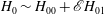 $H_{0}\sim H_{00}+\mathscr{E}H_{01}$
,
$H_{0}\sim H_{00}+\mathscr{E}H_{01}$
,
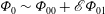 ${\it\Phi}_{0}\sim {\it\Phi}_{00}+\mathscr{E}{\it\Phi}_{01}$
as
${\it\Phi}_{0}\sim {\it\Phi}_{00}+\mathscr{E}{\it\Phi}_{01}$
as
 $\mathscr{E}\rightarrow 0$
. It follows from the leading-order problem that
$\mathscr{E}\rightarrow 0$
. It follows from the leading-order problem that
 $$\begin{eqnarray}H_{00}=X,\quad {\it\Phi}_{00}=1.\end{eqnarray}$$
Thus, for small values of
 $\mathscr{E}$
the effective microscopic contact angle is approximately equal to the microscopic contact angle. We find that the
$\mathscr{E}$
the effective microscopic contact angle is approximately equal to the microscopic contact angle. We find that the
 $\mathit{O}(\mathscr{E})$
-correction to the effective microscopic contact angle is given by
$\mathit{O}(\mathscr{E})$
-correction to the effective microscopic contact angle is given by
 $$\begin{eqnarray}{\it\Phi}_{01}(n)=\int _{0}^{\infty }\int _{v}^{\infty }\frac{u^{1/2}}{u^{3}+u^{n}}\,\text{d}u\,\text{d}v,\end{eqnarray}$$
the integral being finite for
 $n<5/2$
. In particular, we have that
$n<5/2$
. In particular, we have that
 $$\begin{eqnarray}{\it\Phi}_{01}(1)=\frac{{\rm\pi}}{\sqrt{2}},\quad {\it\Phi}_{01}(2)={\rm\pi}.\end{eqnarray}$$
The small-
 $\mathscr{E}$
asymptote is plotted alongside the numerical solution of the boundary-value problem (3.7)–(3.9) in figure 3(b) for
$\mathscr{E}$
asymptote is plotted alongside the numerical solution of the boundary-value problem (3.7)–(3.9) in figure 3(b) for
 $n=1$
and
$n=1$
and
 $n=2$
; we see excellent agreement with the asymptotes in their expected region of validity.
$n=2$
; we see excellent agreement with the asymptotes in their expected region of validity.
B.4 Large-
$\mathscr{E}$
limit

Next we consider the large-
 $\mathscr{E}$
limit. The asymptotic structure consists of three regions. Mass loss enters in a region where
$\mathscr{E}$
limit. The asymptotic structure consists of three regions. Mass loss enters in a region where
 $X=\mathit{O}(\mathscr{E}^{-2/7})$
as
$X=\mathit{O}(\mathscr{E}^{-2/7})$
as
 $\mathscr{E}\rightarrow \infty$
. There is also a region where
$\mathscr{E}\rightarrow \infty$
. There is also a region where
 $X=\mathit{O}(1)$
as
$X=\mathit{O}(1)$
as
 $\mathscr{E}\rightarrow \infty$
and a boundary layer in which the contact-line boundary conditions are satisfied.
$\mathscr{E}\rightarrow \infty$
and a boundary layer in which the contact-line boundary conditions are satisfied.
We begin with the region in which mass loss enters the leading-order balance as
 $\mathscr{E}\rightarrow \infty$
. We scale
$\mathscr{E}\rightarrow \infty$
. We scale
 $X=\mathscr{E}^{-2/7}\overline{X}$
and expand
$X=\mathscr{E}^{-2/7}\overline{X}$
and expand
 $H_{0}(X)\sim H_{\infty }(\overline{X})$
as
$H_{0}(X)\sim H_{\infty }(\overline{X})$
as
 $\mathscr{E}\rightarrow \infty$
. The leading-order thin-film equation is given by
$\mathscr{E}\rightarrow \infty$
. The leading-order thin-film equation is given by
 $$\begin{eqnarray}(H_{\infty }^{3}+H_{\infty }^{n})\frac{\partial ^{3}H_{\infty }}{\partial \overline{X}^{3}}=-\overline{X}^{1/2}\quad \text{for}~\overline{X}>0.\end{eqnarray}$$
This is to be solved subject to the matching conditions
 $$\begin{eqnarray}H_{\infty }=0,\quad \frac{\partial H_{\infty }}{\partial \overline{X}}=0\quad \text{at}~\overline{X}=0^{+};\quad \frac{\partial H_{\infty }}{\partial \overline{X}}\rightarrow {\it\Phi}_{\infty }(n)\quad \text{as}~\overline{X}\rightarrow \infty .\end{eqnarray}$$
The far-field expansion of the solution is analogous to that of the
 $\mathscr{E}=\mathit{O}(1)$
problem (B 3), with (for
$\mathscr{E}=\mathit{O}(1)$
problem (B 3), with (for
 $n<5/2$
)
$n<5/2$
)
 $$\begin{eqnarray}H_{\infty }\sim {\it\Phi}_{\infty }\overline{X}-\frac{8}{3{\it\Phi}_{\infty }^{3}}\overline{X}^{1/2}-\frac{4}{{\it\Phi}_{\infty }^{7}}\log (\overline{X})+\overline{B}_{2}\quad \text{as}~\overline{X}\rightarrow \infty ,\end{eqnarray}$$
where
 ${\it\Phi}_{\infty }(n)$
and
${\it\Phi}_{\infty }(n)$
and
 $\overline{B}_{2}(n)$
are degrees of freedom. The near-field expansion is different due to the boundary condition (B 10b
); we find that
$\overline{B}_{2}(n)$
are degrees of freedom. The near-field expansion is different due to the boundary condition (B 10b
); we find that
 $$\begin{eqnarray}H_{\infty }\sim \left\{\begin{array}{@{}ll@{}}\displaystyle \overline{B}_{3}\overline{X}^{2}+A_{1}\overline{X}^{7/2-2n}\quad & \text{for}~n<3/4,\\ \displaystyle [A_{2}\log ^{4/7}(1/\overline{X})+\overline{B}_{3}]\overline{X}^{2}\quad & \text{for}~n=3/4,\\ \displaystyle A_{3}\overline{X}^{m}+\overline{B}_{3}\overline{X}^{p_{3}}\quad & \text{for}~3/4<n<5/2,\end{array}\right.\end{eqnarray}$$
as
 $\overline{X}\rightarrow 0^{+}$
, where
$\overline{X}\rightarrow 0^{+}$
, where
 $\overline{B}_{3}(n)$
is a degree of freedom; the coefficients
$\overline{B}_{3}(n)$
is a degree of freedom; the coefficients
 $A_{1}(n)$
and
$A_{1}(n)$
and
 $A_{2}(n)$
appearing in the expansions for
$A_{2}(n)$
appearing in the expansions for
 $n<3/4$
and
$n<3/4$
and
 $n=3/4$
, respectively, are given by
$n=3/4$
, respectively, are given by
 $$\begin{eqnarray}A_{1}=-\frac{1}{\overline{B}_{3}^{n}(3/2-2n)(5/2-2n)(7/2-2n)},\quad A_{2}=\left(\frac{7}{8}\right)^{4/7};\end{eqnarray}$$
the coefficient
 $A_{3}(n)$
and the exponent
$A_{3}(n)$
and the exponent
 $m(n)$
appearing in the expansion for
$m(n)$
appearing in the expansion for
 $3/4<n<5/2$
are given by
$3/4<n<5/2$
are given by
 $$\begin{eqnarray}A_{3}=\left[\frac{7(n-3/4)(5/2-n)}{(n+1)^{3}}\right]^{-1/(n+1)},\quad m=\frac{7}{2(n+1)};\end{eqnarray}$$
and
 $p_{3}(n)$
is the real root, satisfying
$p_{3}(n)$
is the real root, satisfying
 $p_{3}>2$
, of the cubic equation in
$p_{3}>2$
, of the cubic equation in
 $p$
,
$p$
,
 $$\begin{eqnarray}p(p-1)(p-2)=\frac{7n(n-3/4)(5/2-n)}{(n+1)^{3}}.\end{eqnarray}$$
Thus, the boundary-value problem (B 9)–(B 10) is correctly specified.
Next we consider the region where
 $X=\mathit{O}(1)$
as
$X=\mathit{O}(1)$
as
 $\mathscr{E}\rightarrow \infty$
. We find that
$\mathscr{E}\rightarrow \infty$
. We find that
 $$\begin{eqnarray}H_{0}(X)\sim \mathscr{E}^{2/7}{\it\Phi}_{\infty }(n)X\quad \text{as}~\mathscr{E}\rightarrow \infty ,\end{eqnarray}$$
so that
 $$\begin{eqnarray}{\it\Phi}_{0}(\mathscr{E},n)\sim {\it\Phi}_{\infty }(n)\mathscr{E}^{2/7}\quad \text{as}~\mathscr{E}\rightarrow \infty .\end{eqnarray}$$
It is the result (B 17) that is key in deriving the
 $7/13$
exponent in the behaviour of the contact-set radius close to extinction (3.30). The large-
$7/13$
exponent in the behaviour of the contact-set radius close to extinction (3.30). The large-
 $\mathscr{E}$
asymptote (B 17) is plotted alongside the numerical solution of the boundary-value problem (3.7) and (3.9) in figure 3(b) for
$\mathscr{E}$
asymptote (B 17) is plotted alongside the numerical solution of the boundary-value problem (3.7) and (3.9) in figure 3(b) for
 $n=1$
and
$n=1$
and
 $n=2$
(with
$n=2$
(with
 ${\it\Phi}_{\infty }(1)$
and
${\it\Phi}_{\infty }(1)$
and
 ${\it\Phi}_{\infty }(2)$
calculated numerically using a similar method to that described in § B.2); we see excellent agreement with the asymptotes in their expected region of validity.
${\it\Phi}_{\infty }(2)$
calculated numerically using a similar method to that described in § B.2); we see excellent agreement with the asymptotes in their expected region of validity.
To be sure that this large-
 $\mathscr{E}$
asymptote is correct, we must consider the boundary layer in which the contact-line boundary conditions are satisfied and check that the leading-order problem in this region is correctly specified. The scalings for this region are obtained by matching with the near-field expansion of the region in which mass loss enters (B 12) and therefore are different for the three cases
$\mathscr{E}$
asymptote is correct, we must consider the boundary layer in which the contact-line boundary conditions are satisfied and check that the leading-order problem in this region is correctly specified. The scalings for this region are obtained by matching with the near-field expansion of the region in which mass loss enters (B 12) and therefore are different for the three cases
 $n<3/4$
,
$n<3/4$
,
 $n=3/4$
and
$n=3/4$
and
 $3/4<n<5/2$
. If
$3/4<n<5/2$
. If
 $n<3/4$
, we find that
$n<3/4$
, we find that
 $$\begin{eqnarray}H_{0}(X)\sim \mathscr{E}^{-4/7}(\widetilde{X}+\overline{B}_{3}\widetilde{X}^{2})\quad \text{as}~\mathscr{E}\rightarrow \infty ,~\text{with}~\widetilde{X}=\mathscr{E}^{4/7}X=\mathit{O}(1).\end{eqnarray}$$
If
 $n=3/4$
, we find that
$n=3/4$
, we find that
 $$\begin{eqnarray}\displaystyle & \displaystyle H_{0}(X)\sim (\mathscr{E}\log \mathscr{E})^{-4/7}(\widetilde{X}+2^{-8/7}\widetilde{X}^{2})\quad \text{as}~\mathscr{E}\rightarrow \infty ,~\text{with}~\widetilde{X}=(\mathscr{E}\log \mathscr{E})^{4/7}X=\mathit{O}(1). & \displaystyle \nonumber\\ \displaystyle & & \displaystyle\end{eqnarray}$$
If
 $3/4<n<5/2$
, the problem is more complicated. We set
$3/4<n<5/2$
, the problem is more complicated. We set
 $X=\mathscr{E}^{-1/(5/2-n)}\widetilde{X}$
and expand
$X=\mathscr{E}^{-1/(5/2-n)}\widetilde{X}$
and expand
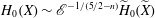 $H_{0}(X)\sim \mathscr{E}^{-1/(5/2-n)}\widetilde{H}_{0}(\widetilde{X})$
as
$H_{0}(X)\sim \mathscr{E}^{-1/(5/2-n)}\widetilde{H}_{0}(\widetilde{X})$
as
 $\mathscr{E}\rightarrow \infty$
. The leading-order problem is
$\mathscr{E}\rightarrow \infty$
. The leading-order problem is
 $$\begin{eqnarray}\widetilde{H}_{0}^{n}\frac{\partial ^{3}\widetilde{H}_{0}}{\partial \widetilde{X}^{3}}=-\widetilde{X}^{1/2}\quad \text{for}~\widetilde{X}>0,\end{eqnarray}$$
subject to
 $$\begin{eqnarray}\widetilde{H}_{0}=0,\quad \frac{\partial \widetilde{H}_{0}}{\partial \widetilde{X}}=1\quad \text{at}~\widetilde{X}=0^{+};\quad \widetilde{H}_{0}\sim A_{1}\widetilde{X}^{m}\quad \text{as}~\widetilde{X}\rightarrow \infty .\end{eqnarray}$$
The near-field expansion of the solution is analogous to that of the
 $\mathscr{E}=\mathit{O}(1)$
problem (B 1), with
$\mathscr{E}=\mathit{O}(1)$
problem (B 1), with
 $$\begin{eqnarray}\widetilde{H}_{0}\sim \widetilde{X}+\left\{\begin{array}{@{}ll@{}}\displaystyle \widetilde{B}_{1}\widetilde{X}^{2}+C_{1}\widetilde{X}^{7/2-n} & \text{for}~3/4<n<3/2,\\ \displaystyle (C_{2}\log (1/\widetilde{X})+\widetilde{B}_{1})\widetilde{X}^{2} & \text{for}~n=3/2,\\ \displaystyle C_{1}\widetilde{X}^{7/2-n}+\widetilde{B}_{1}\widetilde{X}^{2} & \text{for}~3/2<n<5/2,\end{array}\right.\end{eqnarray}$$
as
 $\widetilde{X}\rightarrow 0^{+}$
, where
$\widetilde{X}\rightarrow 0^{+}$
, where
 $\widetilde{B}_{1}(n)$
is a degree of freedom and the coefficients
$\widetilde{B}_{1}(n)$
is a degree of freedom and the coefficients
 $C_{1}(n)$
and
$C_{1}(n)$
and
 $C_{2}$
are defined as in (B 2) but with
$C_{2}$
are defined as in (B 2) but with
 $\mathscr{E}=1$
. The far-field expansion is
$\mathscr{E}=1$
. The far-field expansion is
 $$\begin{eqnarray}\widetilde{H}_{0}\sim A_{1}\widetilde{X}^{m}+\left\{\begin{array}{@{}ll@{}}\displaystyle \widetilde{B}_{2}\widetilde{X}^{p_{2}}+\widetilde{B}_{3}\widetilde{X}^{p_{1}}\quad & \text{for}~3/4<n<n_{-}~\text{or}~n_{+}<n<5/2,\\ \displaystyle (\widetilde{B}_{2}\log \widetilde{X}+\widetilde{B}_{3})\widetilde{X}^{p_{c}}\quad & \text{for}~n=n_{-}~\text{or}~n=n_{+},\\ \displaystyle \widetilde{B}_{2}\widetilde{X}^{p_{r}}\cos (p_{i}\log \widetilde{X}+\widetilde{B}_{3})\quad & \text{for}~n_{-}<n<n_{+},\end{array}\right.\end{eqnarray}$$
as
 $\widetilde{X}\rightarrow \infty$
. Here
$\widetilde{X}\rightarrow \infty$
. Here
 $\widetilde{B}_{2}(n)$
and
$\widetilde{B}_{2}(n)$
and
 $\widetilde{B}_{3}(n)$
are degrees of freedom. The numbers
$\widetilde{B}_{3}(n)$
are degrees of freedom. The numbers
 $n_{-}$
and
$n_{-}$
and
 $n_{+}$
are the two roots satisfying
$n_{+}$
are the two roots satisfying
 $3/4<n_{-}<n_{+}<5/2$
of the cubic equation in
$3/4<n_{-}<n_{+}<5/2$
of the cubic equation in
 $n$
,
$n$
,
 $$\begin{eqnarray}7n(n-3/4)(5/2-n)=\frac{2}{\sqrt{27}}(n+1)^{3}.\end{eqnarray}$$
The real numbers
 $p_{1}(n)$
,
$p_{1}(n)$
,
 $p_{2}(n)$
,
$p_{2}(n)$
,
 $p_{c}(n)$
,
$p_{c}(n)$
,
 $p_{r}(n)$
and
$p_{r}(n)$
and
 $p_{i}(n)$
relate to the roots of the cubic equation (B 15) as follows. If
$p_{i}(n)$
relate to the roots of the cubic equation (B 15) as follows. If
 $3/4<n<n_{-}$
or
$3/4<n<n_{-}$
or
 $n_{+}<n<5/2$
, the cubic has three real roots
$n_{+}<n<5/2$
, the cubic has three real roots
 $p_{1}$
,
$p_{1}$
,
 $p_{2}$
and
$p_{2}$
and
 $p_{3}$
with
$p_{3}$
with
 $0<p_{1}<1-1/\sqrt{3}<p_{2}<1<m<2<p_{3}$
; if
$0<p_{1}<1-1/\sqrt{3}<p_{2}<1<m<2<p_{3}$
; if
 $n=n_{-}$
or
$n=n_{-}$
or
 $n=n_{+}$
, the cubic has a repeated real root
$n=n_{+}$
, the cubic has a repeated real root
 $p_{c}=1-1/\sqrt{3}$
and a third real root
$p_{c}=1-1/\sqrt{3}$
and a third real root
 $p_{3}>2$
; if
$p_{3}>2$
; if
 $n_{-}<n<n_{+}$
, the cubic has two complex-conjugate roots
$n_{-}<n<n_{+}$
, the cubic has two complex-conjugate roots
 $p_{r}\pm \text{i}p_{i}$
with
$p_{r}\pm \text{i}p_{i}$
with
 $0<p_{r}<1-1/\sqrt{3}$
and one real root
$0<p_{r}<1-1/\sqrt{3}$
and one real root
 $p_{3}>2$
. A more detailed analysis of the roots of the cubic equation (B 15) is given by Oliver et al. (Reference Oliver, Whiteley, Saxton, Vella, Zubkov and King2015), where the cubic arises in the analysis of the large-evaporation limit of their problem. We note that
$p_{3}>2$
. A more detailed analysis of the roots of the cubic equation (B 15) is given by Oliver et al. (Reference Oliver, Whiteley, Saxton, Vella, Zubkov and King2015), where the cubic arises in the analysis of the large-evaporation limit of their problem. We note that
 $n_{-}\approx 1.07$
and
$n_{-}\approx 1.07$
and
 $n_{+}\approx 1.88$
, so the particular values
$n_{+}\approx 1.88$
, so the particular values
 $n=1$
and
$n=1$
and
 $n=2$
both correspond to the first case. We deduce from (B 23) that there is a sensitive dependence of the solution on the parameter
$n=2$
both correspond to the first case. We deduce from (B 23) that there is a sensitive dependence of the solution on the parameter
 $n$
: there is a transition from monotonic behaviour to weak capillary ripples as
$n$
: there is a transition from monotonic behaviour to weak capillary ripples as
 $n$
increases through
$n$
increases through
 $n_{-}$
and then a transition back to monotonic behaviour as
$n_{-}$
and then a transition back to monotonic behaviour as
 $n$
increases through
$n$
increases through
 $n_{+}$
. A similar transition of behaviour is found (when a different parameter is varied) in the analysis of evaporation-driven Stokes flow in a wedge (Gelderblom, Bloemen & Snoeijer Reference Gelderblom, Bloemen and Snoeijer2012).
$n_{+}$
. A similar transition of behaviour is found (when a different parameter is varied) in the analysis of evaporation-driven Stokes flow in a wedge (Gelderblom, Bloemen & Snoeijer Reference Gelderblom, Bloemen and Snoeijer2012).
The near- and far-field expansions (B 22) and (B 23) contain a total of three degrees of freedom (namely
 $\widetilde{B}_{1}(n)$
,
$\widetilde{B}_{1}(n)$
,
 $\widetilde{B}_{2}(n)$
and
$\widetilde{B}_{2}(n)$
and
 $\widetilde{B}_{3}(n)$
). This is equal to the order of equation (B 20), so the boundary-layer problem is correctly specified for
$\widetilde{B}_{3}(n)$
). This is equal to the order of equation (B 20), so the boundary-layer problem is correctly specified for
 $3/4<n<5/2$
and thus for all
$3/4<n<5/2$
and thus for all
 $n$
in the range
$n$
in the range
 $n<5/2$
.
$n<5/2$
.


