


1 Introduction
When a moving shock encounters an oblique wedge, shock reflection will occur on the wedge. Two types of wave configurations, including regular reflection (RR) and Mach reflection (MR), were first found by Mach (Reference Mach1878). Since then, more wave configurations such as transitional-Mach reflection (Smith Reference Smith1945) and weak shock reflection (Colella & Henderson Reference Colella and Henderson1990; Vasilev, Elperin & Ben-Dor Reference Vasilev, Elperin and Ben-Dor2008; Skews, Li & Paton Reference Skews, Li and Paton2009) have been found in pseudo-steady shock reflection, while only RR and single-Mach reflection have been observed in steady shock reflection, because the pseudo-steady shock reflection is constituted by two subprocesses, i.e. shock reflection and shock-induced flow deflection (Li & Ben-Dor Reference Li and Ben-Dor1995), whereas the steady shock reflection is a pure shock reflection process. The transitions between RR and irregular reflections are very important in shock reflection studies. von Neumann (Reference von Neumann1943a,Reference von Neumannb) first proposed the detachment criterion which argues that the  $\text{RR}\rightarrow \text{MR}$ transition occurs when the flow deflected angle through the incident shock exceeds the maximum flow deflected angle through the reflected shock. The sonic criterion argues that the
  $\text{RR}\rightarrow \text{MR}$ transition occurs when the corner-generated signals manage to overtake the reflection point. The difference between the predictions from the sonic criterion and the detachment criterion is very small, and it is difficult to distinguish them.
The shock reflection in unsteady flow is more complicated. During a planar shock moving along a double wedge or curved wedge, the wedge angle changes suddenly or continuously, which may cause the wave transition. A systematic study of a planar shock reflection over a plane double wedge was conducted by Ben-Dor, Dewey & Takayama (Reference Ben-Dor, Dewey and Takayama1987), wherein several complicated wave configurations were observed and their transitions discussed. Further studies on the reflection of a planar shock over different kinds of plane double wedge have been performed (Ben-Dor et al. Reference Ben-Dor, Dewey, McMillin and Takayama1988; Li & Ben-Dor Reference Li and Ben-Dor1999; Xie, Han & Takayama Reference Xie, Han and Takayama2005; Yin, Ding & Luo Reference Yin, Ding and Luo2018). The  $\text{RR}\rightarrow \text{MR}$ transition in the reflection of a planar shock over a cylindrical convex wedge was investigated theoretically (Heilig Reference Heilig1969; Itoh, Okazaki & Itaya Reference Itoh, Okazaki and Itaya1981; Suzuki, Adachi & Kobayashi Reference Suzuki, Adachi and Kobayashi1997). These models assumed that the wave transition is determined only by local flow conditions, and the preceding history of the reflection is neglected. However, the theoretical results from these models deviate from the prediction of the pseudo-steady criterion. The
  $\text{RR}\rightarrow \text{MR}$ transition on a convex wedge has also been investigated experimentally (Takayama & Sasaki Reference Takayama and Sasaki1983; Skews & Kleine Reference Skews and Kleine2009, Reference Skews and Kleine2010), and the results showed that the
  $\text{RR}\rightarrow \text{MR}$ transition occurs at markedly smaller angles than those predicted by the known criteria. Inviscid numerical simulations were performed to study the
  $\text{RR}\rightarrow \text{MR}$ transition on a convex wedge (Hakkaki-Fard & Timofeev Reference Hakkaki-Fard and Timofeev2012). Three techniques, including the Mach-number-based technique, the characteristic-based technique and the perturbation technique, were adopted to determine the transition. The results of the Mach-number-based and characteristic-based techniques showed that the sound speed and flow velocity behind the reflected shock are the same as those predicted by two-shock theory, which was originally proposed by von Neumann (Reference von Neumann1943a,Reference von Neumannb) to solve the flow in the vicinity of the reflection point. The results of the perturbation technique showed that the disturbances generated earlier cannot reach the reflection point before the wave transition takes place. As a result, the flow in the vicinity of the reflection point will not be influenced by the preceding history of the reflection off the cylinder, and the
  $\text{RR}\rightarrow \text{MR}$ transition can be predicted by the pseudo-steady criterion. The difference between the experimental and inviscid numerical results was ascribed to the limitation of the temporal and spatial resolutions of the camera (Hakkaki-Fard & Timofeev Reference Hakkaki-Fard and Timofeev2012) and the viscous effect (Kleine et al. Reference Kleine, Timofeev, Hakkaki-Fard and Skews2014).
Recently, high-resolution experiments and inviscid numerical simulations have been conducted to study the  $\text{RR}\rightarrow \text{MR}$ transition on convex surfaces (Geva, Ram & Sadot Reference Geva, Ram and Sadot2018). The authors stated that, different from the shock reflection in pseudo-steady flow, in which the reflected shock wave has only a translation motion along the surface, the reflected shock wave in unsteady shock reflection not only translates but also rotates about the reflection point. The rotation of the reflected shock has an effect on its orientation while the orientation of the reflected shock plays an important role in the reflection process. As a result, the
  $\text{RR}\rightarrow \text{MR}$ transition in unsteady flow is different from that in pseudo-steady flow and cannot be predicted by the pseudo-steady criterion. Further, they concluded that the
  $\text{RR}\rightarrow \text{MR}$ transition occurs when the reflected shock is perpendicular to the incident shock. Besides a single curved surface, the reflection of a planar shock over coupled surfaces has been investigated (Skews & Blitteswijk Reference Skews and Blitteswijk2011; Geva, Ram & Sadot Reference Geva, Ram and Sadot2013; Ram, Geva & Sadot Reference Ram, Geva and Sadot2015; Soni et al. Reference Soni, Hadjadj, Chaudhuri and Ben-Dor2017). These results showed that the wave transition on the second surface will be influenced by the history of the reflection process on the first surface.
To observe the  $\text{RR}\rightarrow \text{MR}$ transition, previous work has primarily concentrated on a planar shock reflection off a convex wedge, in which the shock intensity is constant and only the wedge angle reduces. As we know, the change of the shock intensity will also influence the
  $\text{RR}\rightarrow \text{MR}$ transition. Whether the pseudo-steady criterion can predict the
  $\text{RR}\rightarrow \text{MR}$ transition when a converging or diverging shock reflects off a wedge also needs verification. Besides, the mechanism of the disturbance propagation when a shock propagates along a convex wedge has not been interpreted well, which motivates the current work. In this work, the possible cases for the
  $\text{RR}\rightarrow \text{MR}$ transition when a converging or diverging shock reflects off a wedge are first discussed. The mechanisms of the disturbance propagation over a convex wedge and a straight wedge are interpreted. Extensive inviscid numerical simulations are performed for validation.
2 Classification of the  $\text{RR}\rightarrow \text{MR}$ transition

For a shock reflection over a wedge in perfect air, the shock Mach number and the wedge angle are two crucial factors that influence the reflection type. Several different cases can be classified according to the type of shock and the shape of the wedge. The type of shock can be planar, converging or diverging, while the shape of the wedge can be planar, convex or concave. For a planar shock reflection, the wedge must be convex to observe the  $\text{RR}\rightarrow \text{MR}$ transition in the flow according to previous work.
Except for a planar shock reflection over a convex wedge, the  $\text{RR}\rightarrow \text{MR}$ transition may also occur for a curved shock reflection. Here the reflection of a shock with varied Mach number (including a cylindrically converging shock and a cylindrically diverging shock) off a wedge will be considered. Hornung, Oertel & Sandeman (Reference Hornung, Oertel and Sandeman1979) and Lock & Dewey (Reference Lock and Dewey1989) stated that the sonic criterion is more accurate than the detachment criterion in pseudo-steady shock reflection. However, Geva et al. (Reference Geva, Ram and Sadot2018) proposed that the sonic criterion is necessary but not sufficient whereas the detachment criterion is sufficient in pseudo-steady flow. So far, which criterion is more accurate is still controversial. In this work, the detachment criterion is adopted as the indicator for the
  $\text{RR}\rightarrow \text{MR}$ transition. Note that the present work concentrates on whether the
  $\text{RR}\rightarrow \text{MR}$ transition in unsteady flow would occur under the same condition as that in pseudo-steady flow, and we do not focus on which criterion is more accurate in pseudo-steady flow. We emphasize that the real gas effect is ignored when the shock Mach number is high, and the analysis is restricted to the region where the gas still behaves as a perfect gas. From the detachment criterion, one can calculate that
  $\text{d}\unicode[STIX]{x1D714}_{c}^{d}/\text{d}M_{s}>0$ when
  $M_{s}<2.49$, while
  $\text{d}\unicode[STIX]{x1D714}_{c}^{d}/\text{d}M_{s}<0$ when
  $M_{s}>2.49$ (here
  $\unicode[STIX]{x1D714}_{c}$ is the critical wedge angle when wave transition occurs and the superscript ‘
 $d$’ means the result is determined by the detachment criterion, and
  $M_{s}$ is the shock Mach number). The decrease (increase) of the wedge angle will always promote (inhibit) the
  $\text{RR}\rightarrow \text{MR}$ transition. The increase (decrease) of the shock intensity will promote (inhibit) the
  $\text{RR}\rightarrow \text{MR}$ transition when
  $M_{s}<2.49$, but it will inhibit (promote) the
  $\text{RR}\rightarrow \text{MR}$ transition when
  $M_{s}>2.49$.

Figure 1. (a) Sketch of wedges that guarantee the wedge angle to be constant (i), to reduce (ii) and to increase (iii–v) for converging shock reflection; ICS is the incident converging shock. (b) Sketch of wedges that guarantee the wedge angle to be constant (i), to reduce (ii–iv) and to increase (v) for diverging shock reflection; IDS is the incident diverging shock.
For a converging shock reflection off a wedge, the shock is strengthened as it proceeds. As a result, when  $M_{s}<2.49$ the following subcases are involved for the possible
  $\text{RR}\rightarrow \text{MR}$ transition:
1. The wedge angle is constant. In this case, the wedge must be convex, as indicated by wedge i in figure 1(a), and it needs specific design (Wang et al. Reference Wang, Zhai, Luo, Yang and Lu2017). The increase of shock intensity will promote the
$\text{RR}\rightarrow \text{MR}$ transition.2. The wedge angle reduces. If the curved wedge has a larger curvature than the specific one, as indicated by wedge ii in figure 1(a), the wedge angle will reduce as the converging shock propagates inwards. Both the increase of shock intensity and the reduction of wedge angle will promote the
$\text{RR}\rightarrow \text{MR}$ transition.3. The wedge angle increases. If the wedge is convex with a smaller curvature than the specific one, straight or concave, as indicated by wedges iii, iv and v in figure 1(a), respectively, the wedge angle will increase as the converging shock propagates. Whether the
$\text{RR}\rightarrow \text{MR}$ transition will occur depends on which has a more prominent effect on the wave transition between the increase of shock Mach number and the increase of wedge angle.


When  $M_{s}>2.49$, the increase of shock intensity will restrain the
  $\text{RR}\rightarrow \text{MR}$ transition; thus the wedge angle must reduce if the
  $\text{RR}\rightarrow \text{MR}$ transition is expected to occur, and only the subcase 2 above is possible. Whether the
  $\text{RR}\rightarrow \text{MR}$ transition will occur depends on which has a more prominent effect on the wave transition between the increase of shock Mach number and the reduction of wedge angle.
For a cylindrically diverging shock reflection, the shock is weakened as it propagates outwards. Similar to a converging shock reflection, a specific wedge can be designed to guarantee the constant of the wedge angle for a diverging shock reflection, and the specific wedge must be concave (the design of the specific wedge shape is neglected), as indicated by wedge i in figure 1(b). When  $M_{s}<2.49$, the reduction of shock intensity will restrain the
  $\text{RR}\rightarrow \text{MR}$ transition. Thus the wedge angle must reduce if the
  $\text{RR}\rightarrow \text{MR}$ transition is expected to occur. If the wedge is concave with a smaller curvature than the specific one, straight or convex, as indicated by wedges ii, iii and iv in figure 1(b), respectively, the wedge angle will decrease as the diverging shock propagates. Whether the
  $\text{RR}\rightarrow \text{MR}$ transition can occur depends upon which has a more prominent effect on the wave transition between the decrease of shock Mach number and the decrease of wedge angle.
When  $M_{s}>2.49$, the reduction of shock intensity will promote the
  $\text{RR}\rightarrow \text{MR}$ transition. Except for the subcase mentioned above, two additional subcases are involved for the possible
  $\text{RR}\rightarrow \text{MR}$ transition. When the wedge angle is constant, as indicated by wedge i in figure 1(b), the reduction of shock Mach number may result in the
  $\text{RR}\rightarrow \text{MR}$ transition. When the wedge angle increases (as long as the curvature of the concave wedge is larger than the specific one, as indicated by wedge v in figure 1(b)), whether the
  $\text{RR}\rightarrow \text{MR}$ transition will occur depends on which has a more prominent effect on the wave transition between the decrease of shock Mach number and the increase of wedge angle.
Table 1. Possible cases for the  $\text{RR}\rightarrow \text{MR}$ transition for converging shock reflection in perfect air. Here
  ${\checkmark}$ means possible and ✗ means impossible. The critical shock Mach number
  $M_{s}=2.49$ corresponds to the maximum detachment angle calculated from the detachment criterion for a planar shock reflection in perfect air.

Table 2. Possible cases for the  $\text{RR}\rightarrow \text{MR}$ transition for diverging shock reflection in perfect air. See table 1 for more details.

All possible cases for the occurrence of  $\text{RR}\rightarrow \text{MR}$ transition discussed theoretically from the detachment criterion are listed in tables 1 and 2. From the detachment criterion, when the shock Mach number is relatively low, although
  $\text{d}\unicode[STIX]{x1D714}_{c}^{d}/\text{d}M_{s}$ is significant, the shock Mach number changes quite slowly with the movement of the curved shock according to the Chester–Chisnell–Whitham (CCW) relations (Chester Reference Chester1954; Chisnell Reference Chisnell1957; Whitham Reference Whitham1957), which describe the relationships between the shock strength and the shock cross-sectional area. When the shock intensity is relatively strong, the shock Mach number changes rapidly with the movement of the curved shock; however,
  $\text{d}\unicode[STIX]{x1D714}_{c}^{d}/\text{d}M_{s}$ is very small. As a result, the effect of the shock intensity variation on the
  $\text{RR}\rightarrow \text{MR}$ transition can be considered as a second-order effect. This conclusion has already been reached by Vignati & Guardone (Reference Vignati and Guardone2017), and will be further proven in the appendix in this work by considering a converging shock reflecting over a straight wedge.
Based on this viewpoint, except for the extreme condition that the wedge angle changes quite slowly, the wedge angle variation can be considered to have more prominent effects on wave transition than the shock intensity variation. In other words, for the cases where the wedge angle increases in tables 1 and 2, the transition is impossible or it needs more rigorous initial conditions, and these cases are omitted in this work. According to the wedge shape, three categories, including a shock reflecting off a convex wedge, a curved shock reflecting off a straight and a concave wedge, can be obtained. In this work, the shock reflecting over a concave wedge is beyond the scope of the study, and we will focus on the reflection of a shock over a convex or a straight wedge. Besides a planar shock reflecting off a convex wedge, based on tables 1 and 2, four possible cases for the occurrence of the  $\text{RR}\rightarrow \text{MR}$ transition, including a converging shock reflecting over a convex wedge with constant or reduced wedge angle, and a diverging shock reflecting off a convex or straight wedge with reduced wedge angle, are involved to study the
  $\text{RR}\rightarrow \text{MR}$ transition from the flow-field analysis and numerical simulations.
3 Numerical method and validation
The two-dimensional vectorized adaptive solver (VAS2D) of Sun & Takayama (Reference Sun and Takayama1999), which has been well validated in shock–body interaction (Zhang et al. Reference Zhang, Si, Zhai, Luo, Yang and Lu2016; Wang et al. Reference Wang, Zhai, Luo, Yang and Lu2017) and shock–interface interaction (Zhai et al. Reference Zhai, Si, Luo and Yang2011, Reference Zhai, Wang, Si and Luo2014), is adopted. Two-dimensional compressible Euler equations are adopted as the governing equations. The finite volume method is used to discretize the conservation laws by applying them directly to each non-overlapping control volume. The (monotonic upwind scheme for conservation laws) MUSCL–Hancock approach is adopted to reach a second-order precision in both temporal and spatial scales. To refine the local complex areas and capture the wave configurations effectively, an unstructured adaptive mesh is used. The adaptation procedure refines the mesh in flow regions with large truncation errors and coarsens the grid in flow regions with small truncation errors, while the basis mesh is always retained. A measure for the truncation error at the edge is given by the ratio of the second derivative and the first derivative in the Taylor series expansion of the density. If this truncation error is larger than a specified threshold for refinement, then the cell will be refined; whereas the mesh will be coarsened if this error is smaller than a specified threshold for coarsening.

Figure 2. (a) Computational domain for grid convergence study; IS is the incident shock. (b) Pressure ratio  $p/p_{0}$ profiles with different mesh sizes along the line of
  $y=75~\text{mm}$ at
  $127~\unicode[STIX]{x03BC}\text{s}$ after the shock meets the wedge.
First, the validation of the mesh convergence is performed by considering a planar shock ( $M_{s}=1.3$) reflecting off a convex circular wedge. As sketched in figure 2(a), an inlet condition is applied to the left boundary while solid-wall conditions are applied to the other boundaries and the wedge. The ambient air is assumed to be a perfect gas, and the initial temperature and pressure are 293 K and 101.3 kPa, respectively, and similarly hereinafter. Uniform initial mesh sizes of 0.8, 0.4, 0.2 and 0.1 mm are adopted, respectively. The pressure profiles along
  $y=75~\text{mm}$ at
  $127~\unicode[STIX]{x03BC}\text{s}$ after the shock meets the wedge are extracted, as shown in figure 2(b). As the mesh size reduces, the results are convergent. In this work, to save computational time as much as possible on the premise of ensuring accuracy, the initial mesh size of 0.2 mm and the finest mesh size of
  $25~\unicode[STIX]{x03BC}\text{m}$ in the positions where greater density gradient exists are applied.

Figure 3. Numerical schlieren images of the reflection (a) and zoomed-in images near the reflection point (b): RS, reflected shock; RP, reflection point; PTP, pseudo-triple point; TP, triple point; MS, Mach stem; S, slip line.
To validate the reliability of the pseudo-steady criterion to unsteady shock reflection, it is crucial to determine the moment of triple point formation. As we know, the intersection point of the incident shock with the reflected shock is the reflection point for RR, while it is the triple point for MR. The numerical schlieren images of a planar shock reflecting off a convex circular wedge at early stages are presented in figure 3. To distinguish the triple point, the flows near the reflection point are zoomed in. Before  $t=43~\unicode[STIX]{x03BC}\text{s}$, the intersection point of the incident shock with the reflected shock is located at the wedge and RR occurs. At
  $t=52~\unicode[STIX]{x03BC}\text{s}$, although the intersection point separates from the wedge (the distance between the intersection point and the reflection point is less than half the mesh size, i.e.
  $12.5~\unicode[STIX]{x03BC}\text{m}$), the wave configurations are still similar to that at
  $t=43~\unicode[STIX]{x03BC}\text{s}$, and RR persists. Such an intersection point is defined as the pseudo-triple point (PTP), which is believed to be caused by intrinsic numerical error, and the error must be eliminated for the measurement of Mach stem length. At
  $t=53~\unicode[STIX]{x03BC}\text{s}$, the distance between the intersection point and the reflection point is greater than half the mesh size, and a slip line (S) emerges, indicating the formation of MR. Subsequently, the intersection point moves farther away from the wedge and the Mach stem (MS) is easy to distinguish (
 $t=58~\unicode[STIX]{x03BC}\text{s}$). As a result, when the intersection point of the incident shock with the reflected shock exceeds half the mesh size away from the wedge, it is defined as the triple point and RR transits into MR.

Figure 4. (a) Shock polar plots of a planar shock reflecting over a convex wedge for  $M_{s}=1.3$. (b) Zoomed-in image near the position where the reflected shock polar intersects with the
  $p/p_{0}$ axis. Here
  $\unicode[STIX]{x1D703}$ is the deflection angle; I-1, I-2 and I-3 represent the incident shock polar plots for
  $\unicode[STIX]{x1D714}=65^{\circ }$,
  $60^{\circ }$ and
  $50^{\circ }$, respectively; and R-1, R-2 and R-3 represent the reflected shock polar plots, accordingly.
4 Reflection of shock over a convex wedge
4.1 Mechanism of disturbance propagation over a convex wedge
The perturbation technique, which was first proposed by Skews & Kleine (Reference Skews and Kleine2009), and further used by Hakkaki-Fard & Timofeev (Reference Hakkaki-Fard and Timofeev2012), is a powerful method to study how disturbances affect the flow and the region of the disturbed flow. The basic principle of the perturbation technique is that the disturbance propagates at a velocity that is the vector sum of the flow speed and the sonic speed ahead, which tells that the propagation of the disturbance is highly related to the type of disturbance (compression or rarefaction wave) and the property of flow behind the reflected shock (supersonic or subsonic flow). As proposed by Ben-Dor et al. (Reference Ben-Dor, Dewey and Takayama1987), if the reflection process changes from RR with higher pressures (the pressure behind the reflected shock is  $p_{2}$) to RR with lower pressures, a shock or compression wave will be generated. In the opposite situation, a rarefaction wave will be generated. Taking a planar shock (
 $M_{s}=1.3$) reflecting off a convex wedge in inviscid perfect air, where the wedge angle monotonically reduces while the shock intensity remains unchanged, as an example, figure 4(a) shows the shock polar plots at different wedge angles. To illustrate the variation of
  $p_{2}$, the local region where the reflected shock polar intersects with the
  $p/p_{0}$ axis is zoomed-in as shown in figure 4(b) (
 $p_{0}$ is the pressure in front of the incident shock). It can be found that
  $p_{2}$ changes non-monotonically with the reduction of the wedge angle.
To show the variation of pressure ratio ( $p_{2}/p_{0}$) with wedge angle in detail, assuming that the air is perfect, the exact expression of two-shock theory is adopted, which can be simplified as (Henderson Reference Henderson1982)
 $$\begin{eqnarray}M_{r}^{2}=\frac{C_{1}\pm (C_{1}^{2}-4C_{0})^{1/2}}{2},\end{eqnarray}$$
 with  $C_{0}$ and
  $C_{1}$ given by
 $$\begin{eqnarray}\displaystyle & \displaystyle C_{0}=1-\frac{4(1-\unicode[STIX]{x1D709})^{2}\sin ^{2}\unicode[STIX]{x1D714}}{[(\unicode[STIX]{x1D6FE}-1)+(\unicode[STIX]{x1D6FE}+1)\unicode[STIX]{x1D709}]^{2}}+\frac{[(\unicode[STIX]{x1D6FE}+1)+(\unicode[STIX]{x1D6FE}-1)\unicode[STIX]{x1D709}]^{2}\tan ^{2}\unicode[STIX]{x1D714}}{[(\unicode[STIX]{x1D6FE}-1)+(\unicode[STIX]{x1D6FE}+1)\unicode[STIX]{x1D709}]^{2}}, & \displaystyle\end{eqnarray}$$
 $$\begin{eqnarray}\displaystyle & \displaystyle C_{1}=2+\frac{2(1-\unicode[STIX]{x1D709})^{2}\sin ^{2}\unicode[STIX]{x1D714}}{[(\unicode[STIX]{x1D6FE}-1)+(\unicode[STIX]{x1D6FE}+1)\unicode[STIX]{x1D709}]}+\frac{[(\unicode[STIX]{x1D6FE}+1)+(\unicode[STIX]{x1D6FE}-1)\unicode[STIX]{x1D709}]^{2}\tan ^{2}\unicode[STIX]{x1D714}}{2\unicode[STIX]{x1D6FE}[(\unicode[STIX]{x1D6FE}-1)+(\unicode[STIX]{x1D6FE}+1)\unicode[STIX]{x1D709}]}. & \displaystyle\end{eqnarray}$$
 Here  $M_{r}$ and
  $\unicode[STIX]{x1D714}$ are the reflected shock Mach number and wedge angle, respectively;
  $\unicode[STIX]{x1D709}=p_{0}/p_{1}$, with
  $p_{1}$ the pressure behind the incident shock; and
  $\unicode[STIX]{x1D6FE}$ is the specific heat ratio, which equals 1.4 for perfect air. The positive sign in (4.1) refers to the strong solution while the negative sign refers to the weak solution, which usually occurs (Ben-Dor Reference Ben-Dor2007). As long as
  $M_{r}$ is known, the flow in the vicinity of the reflection point can be completely solved. Provided that the incident shock Mach number
  $M_{s}=1.3$, the variation of
  $p_{2}/p_{0}$ with
  $\unicode[STIX]{x1D714}$ is calculated, as shown in figure 5(a). The specific wedge angle (
 $\unicode[STIX]{x1D714}_{p}^{p}=59.4^{\circ }$, with
  $\unicode[STIX]{x1D714}_{p}$ the wedge angle at which the pressure behind the reflected shock is minimum, and the superscript ‘
 $p$’ denotes planar shock reflection) at which the minimum pressure is reached determines the type of disturbance. From
  $\unicode[STIX]{x1D714}=90^{\circ }$ to
  $\unicode[STIX]{x1D714}=\unicode[STIX]{x1D714}_{p}^{p}=59.4^{\circ }$,
  $p_{2}/p_{0}$ keeps decreasing and the disturbances generated are compression waves (
 $p_{2}$ changes continuously and the disturbance cannot be a shock). From
  $\unicode[STIX]{x1D714}=\unicode[STIX]{x1D714}_{p}^{p}=59.4^{\circ }$ to
  $\unicode[STIX]{x1D714}=\unicode[STIX]{x1D714}_{c}^{d}=46.4^{\circ }$ (the detachment angle that separates RR from MR),
  $p_{2}/p_{0}$ keeps increasing and the disturbances generated are rarefaction waves. The variation of
  $\unicode[STIX]{x1D714}_{p}^{p}$ with
  $M_{s}$ is obtained, as shown in figure 5(b). The angle
  $\unicode[STIX]{x1D714}_{p}^{p}$ reduces as the shock is strengthened.

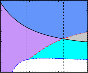
Figure 5. (a) Variation of pressure ratio ( $p_{2}/p_{0}$) with wedge angle when a planar shock with
  $M_{s}=1.3$ moves along a convex wedge. (b) Variations of
  $\unicode[STIX]{x1D714}_{p}^{p}$ (the wedge angle separating the compression wave from the rarefaction wave for planar shock reflection),
  $\unicode[STIX]{x1D714}_{s}$ (the wedge angle separating the subsonic flow from the supersonic flow) and
  $\unicode[STIX]{x1D714}_{c}^{d}$ (the critical wedge angle determined by the detachment criterion) with shock Mach number. Labels I, II, III and IV stand for four different flow regions: I, subsonic flow plus rarefaction wave; II, subsonic flow plus compression wave; III, supersonic flow plus rarefaction wave; and IV, supersonic flow plus compression wave.
The flow properties behind the reflected shock can be calculated by two-shock theory. For  $M_{s}<1.87$, the flow is always subsonic in the laboratory reference frame. For
  $M_{s}>1.87$, the flow properties are dependent on the wedge angle. The variation of wedge angle (
 $\unicode[STIX]{x1D714}_{s}$), determining whether the flow is supersonic or subsonic with shock Mach number, is calculated as shown in figure 5(b). When
  $\unicode[STIX]{x1D714}<\unicode[STIX]{x1D714}_{s}$, the flow is supersonic. When
  $\unicode[STIX]{x1D714}>\unicode[STIX]{x1D714}_{s}$, the flow is subsonic. In particular,
  $\unicode[STIX]{x1D714}_{p}^{p}=\unicode[STIX]{x1D714}_{s}$ when
  $M_{s}=3.16$. Based on the discussion above, the reflection process can be classified according to the shock Mach number
  $M_{s}$.
When  $M_{s}<1.87$, the flow is always subsonic. If
  $\unicode[STIX]{x1D714}<\unicode[STIX]{x1D714}_{p}^{p}$, the disturbance generated is a rarefaction wave, and we classify this as case I (subsonic flow plus rarefaction wave); if
  $\unicode[STIX]{x1D714}>\unicode[STIX]{x1D714}_{p}^{p}$, the disturbance generated is a compression wave, and we classify this as case II (subsonic flow plus compression wave). The reflection process changes from case II to case I as the wedge angle reduces.
When  $1.87<M_{s}<3.16$,
  $\unicode[STIX]{x1D714}_{p}^{p}>\unicode[STIX]{x1D714}_{s}$. If
  $\unicode[STIX]{x1D714}>\unicode[STIX]{x1D714}_{p}^{p}$, the flow is subsonic and the disturbance generated is a compression wave (case II); if
  $\unicode[STIX]{x1D714}_{s}<\unicode[STIX]{x1D714}<\unicode[STIX]{x1D714}_{p}^{p}$, the flow is subsonic and the disturbance generated is a rarefaction wave (case I); if
  $\unicode[STIX]{x1D714}<\unicode[STIX]{x1D714}_{s}$, the flow is supersonic and the disturbance generated is a rarefaction wave, and we classify this as case III (supersonic flow plus rarefaction wave). The reflection process changes from case II to case I and then to case III as the wedge angle reduces.
When  $M_{s}>3.16$,
  $\unicode[STIX]{x1D714}_{s}>\unicode[STIX]{x1D714}_{p}^{p}$. If
  $\unicode[STIX]{x1D714}>\unicode[STIX]{x1D714}_{s}$, the flow is subsonic and the disturbance generated is a compression wave (case II); if
  $\unicode[STIX]{x1D714}_{p}^{p}<\unicode[STIX]{x1D714}<\unicode[STIX]{x1D714}_{s}$, the flow is supersonic and the disturbance generated is a compression wave, and we classify this as case IV (supersonic flow plus compression wave); if
  $\unicode[STIX]{x1D714}<\unicode[STIX]{x1D714}_{p}^{p}$, the flow is supersonic and the disturbance generated is a rarefaction wave (case III). The reflection process changes from case II to case IV and then to case III as the wedge angle reduces.
For a planar shock reflecting off a convex wedge, the wedge angle reduces during the shock propagation. According to the work of Li & Ben-Dor (Reference Li and Ben-Dor1995), the reflection contains two subprocesses: the shock reflection process and the shock-induced flow deflection process. In the following discussion, these two subprocesses will be considered and the perturbation propagation in the four different regions described above will be studied in turn. For simplicity, the smooth convex wedge is assumed to be formed by infinitely many small straight wedges.

Figure 6. The reflection process of a shock over a convex wedge for various cases: SR, shock-induced rarefaction wave; FR, flow-induced rarefaction wave; SC, shock-induced compression wave; ML, Mach line. The subscripts 1 and 2 represent the first and second waves, respectively.
Case I
The reflection process is shown in figure 6(a,b). Assume AB is the first straight wedge and RR persists during the incident shock (IS) moving along it. When IS meets the first corner B, the wedge angle suddenly reduces and the first shock-induced rarefaction wave ( $\text{SR}_{1}$) is generated. As we know, the velocity of disturbance is the vector sum of the flow speed (
 $u$) and the sonic speed (
 $a$) ahead. If the disturbance moves along the wedge, both
  $u$ and
  $a$ are parallel to the wedge. As a result,
  $\text{SR}_{1}$ would move forward at the speed of
  $u_{2}+a_{2}$ (
 $u_{2}$ and
  $a_{2}$ are the flow and sound speeds behind the reflected shock). When the flow propagates from wedge AB to wedge BC, the variation of wedge angle will result in the generation of rarefaction waves to match the boundary conditions of wedge BC. These rarefaction waves are generated by the flow diffraction around the corner, and are called flow-induced rarefaction waves (
 $\text{FR}_{1}$) to distinguish them from
  $\text{SR}_{1}$. The wave
  $\text{FR}_{1}$ can be divided into forward-facing parts moving forwards and the backward-facing parts moving backwards because the flow is subsonic. From gas dynamics theory, a rarefaction wave cannot overtake the other rarefaction wave ahead, i.e.
  $\text{FR}_{1}$ cannot overtake
  $\text{SR}_{1}$. In other words, the diffraction of the subsonic flow which takes place at the first corner B does not change the velocity of
  $\text{SR}_{1}$.
When IS meets the second corner C, a second shock-induced rarefaction wave ( $\text{SR}_{2}$) and second flow-induced rarefaction wave (
 $\text{FR}_{2}$) will be generated successively from the corner C. The movement of
  $\text{SR}_{2}$ is also unaffected by
  $\text{FR}_{2}$. When RR persists,
  $\text{SR}_{1}$ cannot overtake the reflection point. As a result, shortly after
  $\text{FR}_{2}$ formation, the backward-facing parts of
  $\text{FR}_{2}$ do not meet
  $\text{SR}_{1}$ at the wedge BC and the velocity of
  $\text{SR}_{1}$ remains unchanged. Subsequently,
  $\text{SR}_{1}$ will encounter the backward-facing parts of
  $\text{FR}_{2}$ before it arrives at corner C. Note that when the flow and rarefaction wave move in opposite directions, the sound speed reduces while the flow velocity increases after the flow passes through the rarefaction wave, and the relationship of the changes of
  $a$ and
  $u$ is
  $\text{d}a/\text{d}u=-(\unicode[STIX]{x1D6FE}-1)/2$. For perfect air with
  $\unicode[STIX]{x1D6FE}=1.4$, the ratio of changes of
  $a$ and
  $u$ is
  $1:5$. Since the velocity of disturbance is only dependent on the flow ahead,
  $\text{SR}_{1}$ is accelerated after it passes through the backward-facing parts of
  $\text{FR}_{2}$. After
  $\text{SR}_{1}$ passes across the corner C, it moves behind the forward-facing parts of
  $\text{FR}_{2}$ and
  $\text{SR}_{2}$. Because of the properties of rarefaction waves,
  $\text{SR}_{1}$ cannot overtake the forward-facing parts of
  $\text{FR}_{2}$ and
  $\text{SR}_{2}$. As a result, the shock-induced disturbances generated earlier cannot overtake those generated later. In other words, the unsteady flow generated earlier will not influence the flow in the vicinity of the reflection point, and the wave transition is determined by local flow conditions, i.e. the local wedge angle and shock intensity.
Case II
The shock-induced disturbance is a compression wave (SC) and the flow-induced disturbances are rarefaction waves at each corner. Note that the rarefaction wave can overtake the compression wave ahead and the latter will be weakened in strength. However, the velocity of the compression wave remains the same. According to figure 5(a),  $p_{2}/p_{0}$ varies quite slowly when
  $\unicode[STIX]{x1D714}$ reduces from
  $90^{\circ }$ to
  $\unicode[STIX]{x1D714}_{p}^{p}$ (the variation of pressure is only 2 % for
  $M_{s}=1.3$), and therefore the shock-induced compression wave is extremely weak. Further weakened by the rarefaction waves, the compression wave will degenerate to a Mach wave, and the rarefaction waves generated at late stages cannot overtake the Mach wave any more. As indicated in figure 6(c,d), when the Mach wave generated at corner B interacts with the backward-facing parts of the rarefaction waves generated at corner C, the Mach wave will speed up. However, when the Mach wave passes across the corner C, a region of forward-moving rarefaction waves exists between the Mach waves generated at two neighbouring corners. Therefore, the disturbance generated earlier cannot overtake the disturbance generated later, and the flow in the vicinity of the reflection point can be taken as transient pseudo-steady.
Case III
The flow is supersonic and the shock-induced disturbance is a rarefaction wave. At the first corner B as shown in figure 6(e), even the backward-facing parts of the flow-induced rarefaction waves ( $\text{FR}_{1}$) move forwards. As a result, a Mach line (
 $ML_{1}$) will be formed to separate the disturbed region from the undisturbed one. The wave
  $\text{FR}_{1}$ still cannot influence the movement of
  $\text{SR}_{1}$. At the second corner C, similarly,
  $\text{SR}_{2}$ and
  $\text{FR}_{2}$ will be generated. After passing across corner C,
  $\text{SR}_{1}$ will interact with the backward-facing parts of
  $\text{FR}_{2}$, and is accelerated, even though
  $\text{SR}_{1}$ cannot overtake
  $\text{SR}_{2}$ because the rarefaction waves exist between them. As a result, the disturbance generated earlier cannot overtake the disturbance generated later.
Case IV
The shock-induced disturbance is a weak compression wave (SC). As indicated in figure 6(g,h), the backward-facing parts of the flow-induced rarefaction waves (FR) move forwards, and a Mach line is formed. Weakened by FR, SC will finally become a Mach wave. However, the velocity of the Mach wave is unvaried and the flow ahead is unaffected. The forward-facing part of FR generated at a late stage cannot overtake the Mach wave any more. Once the Mach wave generated at the former corner passes through the later corner, it will be accelerated by the backward-facing parts of FR generated at the later corner. However, a region of rarefaction waves still exists between Mach waves generated at two neighbouring corners, and the Mach wave generated earlier cannot overtake the one generated later. In other words, the disturbances generated earlier will not influence the flow in the vicinity of the reflection point.
The analysis tells us that for the reflection of a planar shock over a wedge, as long as the wedge is convex, the flow-induced rarefaction waves always exist between two shock-induced disturbances generated at neighbouring corners. In other words, the flow in the vicinity of the reflection point will not be affected by the unsteady flow caused by the wedge angle variation, and can be taken as transient pseudo-steady. As a result, the  $\text{RR}\rightarrow \text{MR}$ transition can be predicted by the pseudo-steady criterion, regardless of shock intensity, the wedge curvature and the initial wedge angle. In the previous work, the initial wedge angle has already been verified to have no effect on the transition (Skews & Kleine Reference Skews and Kleine2010; Geva et al. Reference Geva, Ram and Sadot2018), which is consistent with the present analysis, and the corresponding validation is omitted in this work. The curvature of a convex wedge was considered to have an effect on the transition (Takayama & Sasaki Reference Takayama and Sasaki1983; Geva et al. Reference Geva, Ram and Sadot2018). However, Kleine et al. (Reference Kleine, Timofeev, Hakkaki-Fard and Skews2014) stated that, when the flow is inviscid or the Reynolds number is very high, the radius of the convex wedge does not affect the
  $\text{RR}\rightarrow \text{MR}$ transition, and the difference between the experimental results (Takayama & Sasaki Reference Takayama and Sasaki1983; Geva et al. Reference Geva, Ram and Sadot2013) and the prediction from the pseudo-steady criterion can largely be attributed to insufficient spatial and temporal resolutions in the experiments. As a result, the effect of wedge curvature on the transition is still controversial.
4.2 Reflection of planar shock over a convex wedge

Figure 7. Computational domains for different models: (a) a convex circular wedge with initial wedge angle  $\unicode[STIX]{x1D714}_{0}=90^{\circ }$; and (b) a convex elliptical wedge. Here
  $R_{1}$ and
  $R_{2}$ are the horizontal and vertical axis radii of the elliptical convex wedge, respectively.
Table 3. The parameters of different models and the corresponding transition wedge angles. Here  $\unicode[STIX]{x1D714}_{c1}^{n}$,
  $\unicode[STIX]{x1D714}_{c2}^{n}$ and
  $\unicode[STIX]{x1D714}_{c3}^{n}$ are the transition wedge angles obtained from numerical simulations for
  $M_{s}=1.5$, 2.5 and 3.5, respectively.

In this section, the dependence of the theory described above on the initial conditions, including the initial shock intensity and the curvature of the convex wedge, will be validated numerically. To investigate the effect of shock intensity on the transition, three different initial shock Mach numbers  $M_{s}=1.5$, 2.5 and 3.5, corresponding to
  $M_{s}<1.87$,
  $1.87<M_{s}<3.16$ and
  $M_{s}>3.16$, respectively, are adopted. To investigate the effect of curvature of the convex wedge, two convex circular wedges with different radii (100 mm for model 1, and 300 mm for model 2) and four different elliptical convex wedges (models 3–6, for which the parameters are listed in table 3) are considered, as shown in figure 7(a,b). Note that the geometrical parameters are chosen with no special purpose in mind. For models 1–6, three shock Mach numbers are all involved to calculate, and the transition wedge angle for each model and each shock Mach number is listed in table 3. The wedge angles just before and after the transition moment are calculated to determine the error. For the shock Mach numbers
  $M_{s}=1.5$, 2.5 and 3.5, the corresponding transition wedge angles determined by the detachment criterion are
  $\unicode[STIX]{x1D714}_{c}^{d}=49.0^{\circ }$,
  $50.8^{\circ }$ and
  $50.6^{\circ }$, respectively. We find that the transition wedge angles obtained from the numerical simulations are slightly smaller than
  $\unicode[STIX]{x1D714}_{c}^{d}$. In the numerical simulations, it is assumed that the transition happens at the moment when the Mach stem can be observed, which is always delayed compared with the moment of Mach stem formation. For different models, the transition wedge angles
  $\unicode[STIX]{x1D714}_{c1}^{n}$,
  $\unicode[STIX]{x1D714}_{c2}^{n}$ and
  $\unicode[STIX]{x1D714}_{c3}^{n}$ (the superscript ‘
 $n$’ means the result is obtained from numerical simulation) for
  $M_{s}=1.5$, 2.5 and 3.5 are, respectively, within
  $48.2\pm 0.5^{\circ }$,
  $48.8\pm 0.5^{\circ }$ and
  $48.1\pm 0.7^{\circ }$. We may conclude that the wave transition can be predicted by the pseudo-steady criterion, regardless of the curvature of the convex wedge and the initial shock Mach number.
4.3 Reflection of converging shock off a convex wedge with constant wedge angle

Figure 8. (a) Process of a converging shock reflecting over a convex wedge with constant wedge angle. Here RPL is the reflection process line, which is used to illustrate the reflection process in the ( $M_{s},\unicode[STIX]{x1D714}$) plane. (b) Shock polar plots of a converging shock reflecting off a convex wedge with constant wedge angle for
  $\unicode[STIX]{x1D714}=50^{\circ }$ at three different moments.
In previous work (Wang et al. Reference Wang, Zhai, Luo, Yang and Lu2017), a converging shock reflection over a curved wedge with constant wedge angle was investigated experimentally and numerically, and both RR and MR were observed. Unfortunately, due to the restricted test section, the effect of shock intensity variation on the development of the Mach stem and wave patterns can hardly be highlighted. The previous work showed that if MR occurs initially when  $M_{s}<2.49$, it will persist because the enhancement of shock strength will promote MR formation. Instead, if RR occurs initially when
  $M_{s}<2.49$, it may transit into MR as the shock converges. Because the shock is strengthened and the wedge angle is constant, the reflection process can be expressed as a straight line that is parallel to the
  $M_{s}$ axis in the (
 $M_{s},\unicode[STIX]{x1D714}$) plane, as shown in figure 8(a). Based on the variation trend of
  $\unicode[STIX]{x1D714}$ with
  $M_{s}$, the
  $\text{RR}\rightarrow \text{MR}$ transition is only possible when
  $M_{s}<2.49$ and the flow regions are located in case I and case III. On the other hand, we have stated that the distributions of the regions of rarefaction wave and compression wave depend on the variation of
  $p_{2}$ during the reflection process, while the distributions of the regions of subsonic flow and supersonic flow are unrelated to the reflection process. Figure 8(b) shows the shock polar plots of a converging shock reflecting over a convex wedge with constant wedge angle for
  $\unicode[STIX]{x1D714}=50^{\circ }$ at three different moments. It can be seen that
  $p_{2}$ increases as the shock Mach number increases, which means that the shock-induced disturbances generated are always rarefaction waves. Thus, only two flow regions exist: subsonic flow plus rarefaction wave (case I), and supersonic flow plus rarefaction wave (case III). According to the discussion in § 4.1, as long as the wedge is convex, flow-induced rarefaction waves always exist between two shock-induced disturbances generated at neighbouring corners. As a result, the
  $\text{RR}\rightarrow \text{MR}$ transition that occurs during the reflection process of a converging shock off a convex wedge with constant wedge angle can be predicted by the pseudo-steady criterion.

Figure 9. (a) Computational domain in numerical simulation. (b) Comparison of critical shock Mach number between the numerical results and the predictions by the detachment criterion.
For validation, numerical simulations are performed. As we know, the pseudo-steady criterion can predict the initial wave configuration, and it shows that, when the wedge angle is small, the critical shock Mach number  $M_{c}^{d}$ (here
  $M_{c}$ is the shock Mach number when the wave transition occurs, and the superscript ‘
 $d$’ means the result is determined by the detachment criterion) is small and changes very slowly with the wedge angle. For such a small wedge angle, the initial shock Mach number (
 $M_{s}$) must be smaller than
  $M_{c}^{d}$ if RR is expected to occur at the beginning. According to the CCW relations, if
  $M_{s}$ is small, the converging shock varies slowly in strength especially with a large shock radius, and the unsteady effect induced by shock strength variation is limited. Moreover, after the
  $\text{RR}\rightarrow \text{MR}$ transition occurs, the Mach stem would grow too slowly to be observed, and the wave transition cannot be precisely observed. Thus the wedge angle should not be too small. To guarantee enough space for shock convergence and Mach stem growth, a large computational domain as sketched in figure 9(a) is adopted, in which the radius and the polar angle of the leading edge in the polar coordinate system are
  $r_{0}=800~\text{mm}$ and
  $\unicode[STIX]{x1D703}_{0}=60^{\circ }$, respectively. The shape of the curved wedge is designed according to our previous work (Wang et al. Reference Wang, Zhai, Luo, Yang and Lu2017). The position of the initial converging shock is set at 810 mm away from the converging centre. Solid-wall conditions are applied to the upper and lower boundaries and the curved wedge, while an inlet condition is applied to the right boundary. The initial post-shock flow is regarded as uniform. Thirteen different initial wedge angles,
  $35^{\circ }$,
  $40^{\circ }$ to
  $50^{\circ }$ with
  $1^{\circ }$ increments and
  $50.5^{\circ }$, are adopted. For each case, the critical shock Mach number obtained by the detachment criterion
  $M_{c}^{d}$ is shown in table 4. To capture the
  $\text{RR}\rightarrow \text{MR}$ transition, the initial shock Mach numbers that are smaller than the corresponding critical ones are chosen and listed in table 4.
We have numerically simulated the converging shock reflection off the curved wedge for each case. The definition and identification of the triple point are the same as in the planar shock case because both the incident converging shock and the reflected shock can be considered as planar in local regions. After the transition position is determined, the shock Mach number at the transition position can be obtained through the CCW relations. For all wedge angles, the corresponding critical shock Mach numbers determined from the numerical simulations  $M_{c}^{n}$ are shown in figure 9(b). It is found that the numerical results are in good agreement with the predictions by the detachment criterion. In other words, the pseudo-steady criterion can predict the unsteady
  $\text{RR}\rightarrow \text{MR}$ transition.
4.4 Reflection of converging shock over a curved wedge with reduced wedge angle
The discussion above shows that the  $\text{RR}\rightarrow \text{MR}$ transition in unsteady flow caused by the variation of either wedge angle or shock intensity can be predicted by the pseudo-steady criterion. When a converging shock reflects off a general convex wedge, both the shock strength and the wedge angle change. Whether the
  $\text{RR}\rightarrow \text{MR}$ transition can be predicted by the pseudo-steady criterion in such an unsteady flow needs consideration. In this section, the reflection of a converging shock over a curved wedge with reduced wedge angle is considered. A curved wedge that guarantees the wedge angle constant can be considered as a planar one if the converging shock is approximately treated as a planar shock. To ensure the reduction of the wedge angle, the specified wedge in polar coordinates is designed by transforming the convex circular wedge in Cartesian coordinates.

Figure 10. (a) Schematic of a planar shock reflecting over a convex circular wedge with  $\unicode[STIX]{x1D714}_{0}<90^{\circ }$. (b) Schematic of designing the specified curved wedge based on the polar coordinate system centred on convergence centre O.
Table 4. The critical shock Mach number obtained by the detachment criterion  $M_{c}^{d}$ and the initial shock Mach number
  $M_{s}$ for different wedge angles.
For a planar shock reflection over a convex circular wedge with  $\unicode[STIX]{x1D714}_{0}<90^{\circ }$, as shown in figure 10(a), when the shock moves a distance of
  $l$ from the leading edge of the convex wedge, the corresponding wedge angle is
  $\unicode[STIX]{x1D714}=\arcsin [(R\sin \unicode[STIX]{x1D714}_{0}-l)/R]$. To transform the convex circular wedge from the Cartesian coordinate system to the polar one, when the converging shock moves a distance of
  $r_{0}-r=l$ from the leading edge, the corresponding wedge angle must be the same as that in Cartesian coordinates, i.e.
 $$\begin{eqnarray}\unicode[STIX]{x1D714}=\arcsin \left[\frac{R\sin \unicode[STIX]{x1D714}_{0}-(r_{0}-r)}{R}\right].\end{eqnarray}$$
 For given  $\unicode[STIX]{x1D714}_{0}$,
  $R$ and
  $r_{0}$,
  $\unicode[STIX]{x1D714}$ is only related to
  $r$. The curved wedge in polar coordinates can be divided into an enormous number of small parts, and each part can be considered to be straight as long as it is short enough. Assume that AB is the first part of the wedge, as shown in figure 10(b); the positions of points A and B can be expressed as (
 $r_{0},\unicode[STIX]{x1D703}_{0}$) and (
 $r_{1},\unicode[STIX]{x1D703}_{1}$), respectively, in polar coordinates with
  $r_{0}$ (
 $r_{1}$) and
  $\unicode[STIX]{x1D703}_{0}$ (
 $\unicode[STIX]{x1D703}_{1}$) the radius and polar angle of point A (B), respectively. Provided that the converging shock moves a distance of
  $\text{d}r$ from point A to B, i.e.
  $r_{1}=r_{0}-\text{d}r$, the polar angle of point B (
 $\unicode[STIX]{x1D703}_{1}$) can be obtained by the geometrical relation
 $$\begin{eqnarray}\unicode[STIX]{x1D703}_{1}=\unicode[STIX]{x1D703}_{0}-\text{d}\unicode[STIX]{x1D703}_{1}\approx \unicode[STIX]{x1D703}_{0}-\frac{1}{r_{0}\cot \unicode[STIX]{x1D714}_{0}}\,\text{d}r=\unicode[STIX]{x1D703}_{0}-\frac{R\sin \unicode[STIX]{x1D714}_{0}-(r_{0}-r_{0})}{r_{0}\sqrt{R^{2}-[R\sin \unicode[STIX]{x1D714}_{0}-(r_{0}-r_{0})]^{2}}}\,\text{d}r.\end{eqnarray}$$
 Similarly, for the converging shock wave moving a distance of  $\text{d}r$ from point B to C, i.e.
  $r_{2}=r_{1}-\text{d}r$, the polar angle of point C (
 $\unicode[STIX]{x1D703}_{2}$) can be obtained by the similar relation
 $$\begin{eqnarray}\unicode[STIX]{x1D703}_{2}=\unicode[STIX]{x1D703}_{1}-\text{d}\unicode[STIX]{x1D703}_{2}\approx \unicode[STIX]{x1D703}_{1}-\frac{1}{r_{1}\cot \unicode[STIX]{x1D714}_{1}}\,\text{d}r=\unicode[STIX]{x1D703}_{1}-\frac{R\sin \unicode[STIX]{x1D714}_{0}-(r_{0}-r_{1})}{r_{1}\sqrt{R^{2}-[R\sin \unicode[STIX]{x1D714}_{0}-(r_{0}-r_{1})]^{2}}}\,\text{d}r.\end{eqnarray}$$
The geometrical relations above can be extended to obtain the final shape of the curved wedge.

Figure 11. The process of a converging shock reflecting off a specified convex wedge with  $r_{0}=180~\text{mm}$,
  $\unicode[STIX]{x1D703}_{0}=25^{\circ }$,
  $R=275~\text{mm}$ and
  $\unicode[STIX]{x1D714}_{0}=70^{\circ }$ for
  $M_{1}=1.68$.

Figure 12. (a) Shock polar plots and (b) variation of  $p_{2}/p_{0}$ with
  $\unicode[STIX]{x1D714}$ of converging shock off a specified convex wedge with
  $r_{0}=180~\text{mm}$,
  $\unicode[STIX]{x1D703}_{0}=25^{\circ }$,
  $R=275~\text{mm}$ and
  $\unicode[STIX]{x1D714}_{0}=70^{\circ }$ for
  $M_{1}=1.68$.
When a converging shock reflects over a convex wedge with reduced wedge angle, the reflection process can be expressed by a curved line in the ( $M_{s},\unicode[STIX]{x1D714}$) plane, as indicated in figure 11 because the wedge angle reduces as the shock Mach number increases (
 $M_{s}$ at each position is calculated by the CCW relations). Assuming that
  $M_{1}=1.68$ (
 $M_{1}$ is the shock Mach number when the shock meets the wedge),
  $r_{0}=180~\text{mm}$,
  $\unicode[STIX]{x1D703}_{0}=25^{\circ }$,
  $R=275~\text{mm}$ and
  $\unicode[STIX]{x1D714}_{0}=70^{\circ }$, because the initial
  $\unicode[STIX]{x1D714}_{0}$ is greater than
  $\unicode[STIX]{x1D714}_{p}^{p}$, the curved line representing the reflection process will intersect with the
  $\unicode[STIX]{x1D714}_{p}^{p}$ line in the (
 $M_{s},\unicode[STIX]{x1D714}$) plane. For the case studied, the intersection point can be calculated as (
 $1.72,57.4^{\circ }$). For a planar shock with
  $M_{s}=1.72$ reflection over a convex circular wedge, the minimum pressure is reached when
  $\unicode[STIX]{x1D714}=57.4^{\circ }$. However, for a converging shock reflection, when the shock Mach number
  $M_{s}=1.72$ and the wedge angle
  $\unicode[STIX]{x1D714}=57.4^{\circ }$, the minimum pressure is not reached, as shown in figure 12(a), in which the shock polar plots are drawn for three shock Mach numbers and corresponding wedge angles. This fact shows that the distribution of the flow regions in the reflection of a converging shock over a convex wedge with reduced wedge angle is different from that in planar shock case, because the variation of shock Mach number also changes the pressure behind the reflected shock wave.
The variation of  $p_{2}/p_{0}$ with
  $\unicode[STIX]{x1D714}$ during the converging shock reflection process is given in figure 12(b), from which
  $p_{2}$ always increases with the reduction of the wedge angle, i.e. the shock-induced disturbances generated are always rarefaction waves. Before the reflection process line meets the
  $\unicode[STIX]{x1D714}_{p}^{p}$ line, the reduction of the wedge angle restrains the growth of pressure
  $p_{2}$ while the enhancement of shock Mach number promotes the growth of pressure
  $p_{2}$. The continuous growth of
  $p_{2}$ observed from figure 12(b) means that the increase of shock Mach number has a more prominent effect on the variation of
  $p_{2}$ than the reduction of the wedge angle. After the reflection process line meets the line
  $\unicode[STIX]{x1D714}_{p}^{p}$, both the reduction of the wedge angle and the increase of the shock Mach number promote the growth of
  $p_{2}$. As a result, for a converging shock reflection with reduced wedge angle, if
  $p_{2}$ has a minimum value, the corresponding wedge angle must be larger than the wedge angle at which the reflection process line intersects with the
  $\unicode[STIX]{x1D714}_{p}^{p}$ line.
Although the distribution of the flow regions in the converging shock case differs from that in the planar shock case, all the possible flow regions are included in those proposed above, and the analysis for the planar shock case can be applied to the curved shock case as long as the wedge is convex. Therefore, the  $\text{RR}\rightarrow \text{MR}$ transition in the reflection of a converging shock off a convex wedge with reduced wedge angle can be predicted by the pseudo-steady criterion. For numerical validation, six different cases as shown in table 5 are chosen. For all cases, the shock Mach number is 1.68 when the converging shock meets the wedge, and
  $r_{0}=180~\text{mm}$,
  $\unicode[STIX]{x1D703}_{0}=25^{\circ }$. The computational domain and boundary conditions are the same as those adopted in our previous work (Wang et al. Reference Wang, Zhai, Luo, Yang and Lu2017). The transition wedge angles
  $\unicode[STIX]{x1D714}_{c}^{n}$ and the corresponding shock Mach number obtained from the computations
  $M_{c}^{n}$, as well as the critical wedge angle determined by the detachment criterion
  $\unicode[STIX]{x1D714}_{c}^{d}$, are shown in table 5. It is found that the
  $\text{RR}\rightarrow \text{MR}$ transition can be predicted by the pseudo-steady criterion, and is unrelated to the curvature of the convex wedge and the initial wedge angle.

Figure 13. (a) The process of a diverging shock reflecting off a specified convex wedge and (b) the variation of  $p_{2}/p_{0}$ with
  $\unicode[STIX]{x1D714}$. Here
  $r_{0}=100~\text{mm}$,
  $\unicode[STIX]{x1D703}_{0}=25^{\circ }$,
  $R=150~\text{mm}$ and
  $\unicode[STIX]{x1D714}_{0}=60^{\circ }$ for
  $M_{1}=2.0$.
Table 5. The parameters of six different specified curved wedges and the values of the transition wedge angles as well as the corresponding shock Mach numbers.

4.5 Reflection of diverging shock over a curved wedge with reduced wedge angle
Similar to a cylindrically converging shock reflection, a concave wedge can be designed for a cylindrically diverging shock reflection to guarantee the constancy of the wedge angle. Here we focus on the reflection of a diverging shock on a convex wedge, in which the wedge angle reduces and the  $\text{RR}\rightarrow \text{MR}$ transition is possible. Again, a convex circular wedge in the Cartesian coordinate system is transformed into a special one in the polar coordinate system. The design of the specified curved wedge is similar to that in the converging case, and is neglected. If
  $r_{0}$,
  $\unicode[STIX]{x1D703}_{0}$,
  $R$ and
  $\unicode[STIX]{x1D714}_{0}$ are given, the shape of the special convex wedge can be determined. As indicated in converging shock reflection, the increase of shock intensity will change the distribution of the flow regions. In this section, we will consider the effect of shock intensity reduction on the distribution of the flow regions.

Figure 14. (a) Shock polar plots of the reflection process of a diverging shock off a specified convex wedge with  $r_{0}=100~\text{mm}$,
  $\unicode[STIX]{x1D703}_{0}=25^{\circ }$,
  $R=150~\text{mm}$ and
  $\unicode[STIX]{x1D714}_{0}=60^{\circ }$ for
  $M_{1}=2.0$. (b) The zoomed in image near the position where the R polar meets the
  $p/p_{0}$ axis.
Assuming that the initial conditions are  $r_{0}=100~\text{mm}$,
  $\unicode[STIX]{x1D703}_{0}=25^{\circ }$,
  $R=150~\text{mm}$,
  $\unicode[STIX]{x1D714}_{0}=60^{\circ }$ and
  $M_{1}=2$, the process of a diverging shock reflecting off a convex wedge can also be expressed as a curved line in the (
 $M_{s},\unicode[STIX]{x1D714}$) plane, as shown in figure 13(a). The position where the reflection process line intersects with the
  $\unicode[STIX]{x1D714}_{p}^{p}$ line is obtained from figure 13 as (
 $1.99,56.5^{\circ }$). Figure 14(a) shows the shock polar plots of the reflection process at three different positions. To illustrate the variation of
  $p_{2}$, the local area near the position where the
  $R$ polar meets the
  $p/p_{0}$ axis is zoomed-in as shown in figure 14(b). It is found that
  $p_{2}$ continues to reduce after the reflection process line meets the
  $\unicode[STIX]{x1D714}_{p}^{p}$ line and subsequently increases. In other words, the wedge angle at which
  $p_{2}$ reaches the minimum value is smaller than the wedge angle at which the reflection process line meets the
  $\unicode[STIX]{x1D714}_{p}^{p}$ line. The variation of
  $p_{2}/p_{0}$ with
  $\unicode[STIX]{x1D714}$ during the reflection process is given in figure 13(b), from which
  $p_{2}$ keeps decreasing until
  $\unicode[STIX]{x1D714}=\unicode[STIX]{x1D714}_{p}^{d}=53.8^{\circ }$ (
 $\unicode[STIX]{x1D714}_{p}^{d}$ with the superscript ‘
 $d$’ denoting the diverging shock case). Before the reflection process line meets the
  $\unicode[STIX]{x1D714}_{p}^{p}$ line, both the decrease of wedge angle and the decrease of shock Mach number restrain the growth of
  $p_{2}$. After the reflection process line meets the
  $\unicode[STIX]{x1D714}_{p}^{p}$ line, the decrease of wedge angle promotes the growth of
  $p_{2}$ while the decrease of shock Mach number restrains the growth of
  $p_{2}$, and their effects are offset when
  $\unicode[STIX]{x1D714}=\unicode[STIX]{x1D714}_{p}^{d}=53.8^{\circ }$. After this moment, the effect of reduction of the wedge angle on the variation of
  $p_{2}$ becomes stronger, resulting in the increase of
  $p_{2}$. For the diverging shock reflection, regions of both rarefaction and compression waves exist. The analysis for planar shock reflection can be applied to the diverging shock case as long as the wedge is convex, and thus the
  $\text{RR}\rightarrow \text{MR}$ transition during the reflection of a diverging shock off a convex wedge with reduced wedge angle can be predicted by the pseudo-steady criterion.
Numerical simulations are carried out for validation. The curved wedge and the computational domain are sketched in figure 15. The radius of the leading edge is  $r_{0}=100~\text{mm}$ and the polar angle of the trailing edge is
  $\unicode[STIX]{x1D703}_{0}=25^{\circ }$. The initial diverging shock is positioned at
  $r_{s}=90~\text{mm}$ away from the diverging centre and its Mach number is 2.0. To guarantee a convex wedge, six different
  $R$ and
  $\unicode[STIX]{x1D714}_{0}$ are chosen carefully, as shown in table 6. The transition wedge angles are obtained and shown in table 6, from which the
  $\text{RR}\rightarrow \text{MR}$ transition can still be predicted by the pseudo-steady criterion and is unrelated to the curvature of the convex wedge and the initial wedge angle.

Figure 15. Sketch of computational domain for diverging shock reflection.
Table 6. The parameters of six different specified curved wedges and the values of the transition wedge angles as well as the corresponding shock Mach numbers.

5 Reflection of cylindrically diverging shock over a straight wedge
For a diverging shock reflecting off a straight wedge, only shock-induced disturbances exist and flow-induced disturbances are absent. If the shock-induced disturbances generated at two neighbouring positions are rarefaction waves, no matter whether the flow is supersonic or subsonic, the rarefaction waves generated earlier cannot overtake those generated later. However, if the disturbances are compression waves, the compression waves can overtake each other to generate a stronger wave. It is necessary to figure out whether the superposition of the compression waves will affect the transition. The variation of  $p_{2}$ in this case is similar to that in the reflection of a diverging shock over a convex wedge with reduced wedge angle; both the wedge angle and the shock Mach number decrease during the reflection process, which leads to
  $\unicode[STIX]{x1D714}_{p}^{d}$ being always smaller than the wedge angle at which the reflection process line meets the
  $\unicode[STIX]{x1D714}_{p}^{p}$ line.

Figure 16. (a) Schematic of a cylindrically diverging shock reflection over a straight wedge. Point O is the diverging centre. (b) Variations of  $u_{R}$,
  $u_{sup}$ and
  $u_{R}-u_{sup}$ with diverging shock Mach number
  $M_{90}$ at
  $\unicode[STIX]{x1D714}=\unicode[STIX]{x1D714}_{90}$.
Assume that  $Q$ is the last point on the wedge with wedge angle greater than
  $\unicode[STIX]{x1D714}_{p}^{d}$ and
  $N$ is the first point on the wedge with wedge angle less than
  $\unicode[STIX]{x1D714}_{p}^{d}$, i.e. the last compression wave is generated at point
  $Q$ while the first rarefaction wave is generated at point
  $N$. The compression wave generated at point
  $Q$ will be strengthened by the compression waves generated earlier. If a stronger compression wave is generated by the superposition of the weak compression waves, as stated earlier, it will not overtake the rarefaction waves generated later, and thus will not affect the reflection point. Instead, if a shock wave is generated by the superposition of the weak compression waves, it will obtain the largest velocity at the position with
  $\unicode[STIX]{x1D714}=\unicode[STIX]{x1D714}_{p}^{d}$, because the rarefaction waves will be generated when
  $\unicode[STIX]{x1D714}<\unicode[STIX]{x1D714}_{p}^{d}$ and weaken the shock wave.
Here we will focus on the velocity relation between the reflection point and the disturbances along the wedge. Note that the shock wave is superimposed by a series of compression waves generated due to the pressure change behind the reflected shock as the wedge angle reduces from  $\unicode[STIX]{x1D714}=90^{\circ }$ to
  $\unicode[STIX]{x1D714}=\unicode[STIX]{x1D714}_{p}^{d}$. Assuming that the pressure dramatically drops from
  $p_{90}$ at
  $\unicode[STIX]{x1D714}=90^{\circ }$ to
  $p_{p}^{d}$ at
  $\unicode[STIX]{x1D714}=\unicode[STIX]{x1D714}_{p}^{d}$, according to one-dimensional gas dynamics theory, the Mach number of the shock (
 $M_{sup}$) created by the compression wave superposition at
  $\unicode[STIX]{x1D714}=\unicode[STIX]{x1D714}_{p}^{d}$ can be expressed as
 $$\begin{eqnarray}M_{sup}=\left[\frac{(\unicode[STIX]{x1D6FE}+1)p_{90}}{2\unicode[STIX]{x1D6FE}p_{p}^{d}}+\frac{\unicode[STIX]{x1D6FE}-1}{2\unicode[STIX]{x1D6FE}}\right]^{1/2}.\end{eqnarray}$$
 In this expression, the two quantities  $p_{p}^{d}$ and
  $p_{90}$ need to be solved. Note that
  $p_{90}$ is the pressure behind the reflected shock when
  $\unicode[STIX]{x1D714}$ approaches
  $90^{\circ }$ (
 $p_{2}$ is unsolvable when
  $\unicode[STIX]{x1D714}=90^{\circ }$). Assuming that
  $M_{90}$ and
  $R_{90}$ are the shock Mach number and radius of the diverging shock at
  $\unicode[STIX]{x1D714}=90^{\circ }$, then
  $p_{90}$ can be directly solved through the two-shock theory. Based on the geometric relation as shown in figure 16(a), the wedge angle
  $\unicode[STIX]{x1D714}$ at an arbitrary position can be obtained by
  $\unicode[STIX]{x1D714}=\arcsin (R_{90}/R)$ with
  $R$ being the radius of the diverging shock at an arbitrary position. According to the CCW relations, if
  $M_{90}$ and
  $R_{90}/R$ are known, the shock intensity at an arbitrary position (
 $M_{s}$) can be obtained. After the wedge angle and shock Mach number at an arbitrary position are known,
  $p_{2}$ can be calculated. By the iterative method,
  $p_{p}^{d}$,
  $\unicode[STIX]{x1D714}_{p}^{d}$ and the shock Mach number at
  $\unicode[STIX]{x1D714}=\unicode[STIX]{x1D714}_{p}^{d}$ (
 $M_{p}^{d}$) can be calculated. Subsequently, the maximum velocity of the shock wave created along the wedge can be expressed as
  $u_{sup}=u_{p}^{d}+M_{sup}a_{p}^{d}$ (with
  $u_{p}^{d}$ and
  $a_{p}^{d}$ the flow and sound speeds behind the reflected shock at
  $\unicode[STIX]{x1D714}=\unicode[STIX]{x1D714}_{p}^{d}$).
As the diverging shock moves outwards, both the shock velocity and the wedge angle reduce. The velocity of the reflection point is  $u_{R}=u_{s}/\cos \unicode[STIX]{x1D714}=M_{s}a_{0}/\cos \unicode[STIX]{x1D714}$, where
  $u_{s}$ is the velocity of the diverging shock, and
  $a_{0}$ is the sonic speed in front of the diverging shock. From the expression, the velocity of the reflection point gradually decreases as the shock diverges. As a result, the reflection point obtains the smallest velocity at the transition point with
  $\unicode[STIX]{x1D714}=\unicode[STIX]{x1D714}_{c}^{d}$. To acquire such a velocity, the wedge angle
  $\unicode[STIX]{x1D714}_{c}^{d}$ and the diverging shock Mach number
  $M_{c}^{d}$ at
  $\unicode[STIX]{x1D714}=\unicode[STIX]{x1D714}_{c}^{d}$ should be solved. As we know, as the shock Mach number reduces, the corresponding
  $\unicode[STIX]{x1D714}_{c}^{d}$ also changes. As described in the last paragraph, at an arbitrary position, the wedge angle
  $\unicode[STIX]{x1D714}$ and the shock Mach number
  $M_{s}$ can be obtained. Before the detachment criterion is reached,
  $\unicode[STIX]{x1D714}$ is larger than
  $\unicode[STIX]{x1D714}_{c}^{d}$. By the iterative method, the radius (
 $R_{c}^{d}$) and shock Mach number (
 $M_{c}^{d}$) of the diverging shock at
  $\unicode[STIX]{x1D714}=\unicode[STIX]{x1D714}_{c}^{d}$ can be obtained, and then the minimum velocity of the reflection point
  $u_{R}$ is known. The variations of
  $u_{R}$ and
  $u_{sup}$ with
  $M_{90}$ are shown in figure 16(b), from which
  $u_{R}$ is always larger than
  $u_{sup}$, and the velocity difference
  $u_{R}-u_{sup}$ is increasing with the increase of
  $M_{90}$. In other words, the maximum velocity of the disturbance is still smaller than the minimum velocity of the reflection point. As a result, the disturbances generated earlier cannot overtake the reflection point before the pseudo-steady criterion is reached, and will not exert any effect on the
  $\text{RR}\rightarrow \text{MR}$ transition.

Figure 17. Reflection processes for cases with different  $M_{1}$ and
  $\unicode[STIX]{x1D714}_{0}$: (a)
  $M_{1}=2.5$ and (b)
  $M_{1}=3.5$. The dashed lines represent the flow region II; the dotted lines represent the flow region I; the dash-dotted lines represent the flow region III; and the short dashed lines represent the flow region IV.
For the reflection of a diverging shock off a straight wedge, a similar computational domain as sketched in figure 15 is adopted. The curved wedge is substituted by a straight one, and  $\unicode[STIX]{x1D703}_{0}=45^{\circ }$. The other initial and boundary conditions are the same as those in § 4.5. Four different initial wedge angles
  $\unicode[STIX]{x1D714}_{0}=60^{\circ }$,
  $70^{\circ }$,
  $80^{\circ }$ and
  $90^{\circ }$ are adopted. Three different initial shock Mach numbers
  $M_{s}=1.52$, 2.55 and 3.57 are adopted. When the diverging shock meets the leading edge of the straight wedge, the shock Mach number reduces to
  $M_{1}=1.5$, 2.5 and 3.5, respectively. Taking
  $M_{1}=2.5$ and 3.5, for example, the variation of shock Mach number with wedge angle is shown in figure 17. With different
  $\unicode[STIX]{x1D714}_{0}$, the reflection process changes from case II to case I and then to case III for
  $M_{1}=2.5$, while the reflection process changes from case II to case IV and then to case III for
  $M_{1}=3.5$. As a result, three different reflection processes are all included. Figure 17 verifies that the distribution of the flow regions for a diverging shock reflection differs from that for a planar shock reflection. The transition wedge angle
  $\unicode[STIX]{x1D714}_{c}^{n}$ and the shock Mach number
  $M_{c}^{n}$ when the
  $\text{RR}\rightarrow \text{MR}$ transition happens are obtained and shown in table 7. We can conclude that the
  $\text{RR}\rightarrow \text{MR}$ transition can be predicted by the pseudo-steady criterion, and is unrelated to the initial wedge angle and shock intensity.
Table 7. The values of the transition wedge angles and the shock Mach numbers when the transition happens for cases with different  $M_{1}$ and
  $\unicode[STIX]{x1D714}_{0}$. Here
  $M_{1}$ is the shock Mach number when the diverging shock meets the leading edge of the straight wedge.

Table 8. The summary of the main results in the present work.

In summary, for a shock reflecting over a convex wedge in inviscid flow, the unsteady flow induced by the wedge angle variation or by the shock intensity variation will not influence the flow in the vicinity of the reflection point, because the disturbances generated earlier are isolated by the flow-induced rarefaction waves from the disturbances generated later. As a result, the  $\text{RR}\rightarrow \text{MR}$ transition can be predicted by the pseudo-steady criterion. For a diverging shock reflection over a straight wedge, the maximum velocity of the disturbance is still smaller than the minimum velocity of the reflection point; thus, the flow in the vicinity of the reflection point will not be influenced by the unsteady flow and the
  $\text{RR}\rightarrow \text{MR}$ transition can be predicted by the pseudo-steady criterion. Table 8 summarizes the main results of the present work, including the cases for the
  $\text{RR}\rightarrow \text{MR}$ transition and the reliability of the pseudo-steady criterion for predicting the transition.
6 Conclusions
The  $\text{RR}\rightarrow \text{MR}$ transition in inviscid perfect air for shock reflection over convex and straight wedges is investigated. The possible cases for the occurrence of the
  $\text{RR}\rightarrow \text{MR}$ transition are classified. According to the detachment criterion, a critical shock Mach number corresponding to the maximum detachment angle is obtained. Separated by the critical shock Mach number, the variation of the detachment wedge angle with the shock Mach number is different. Based on the fact that the variation of the shock Mach number has a second-order effect on the wave transition, if one expects to observe the
  $\text{RR}\rightarrow \text{MR}$ transition, except for a planar shock reflecting over a convex wedge, four other cases, including a converging shock reflecting over a convex wedge with constant or reduced wedge angle, and a diverging shock reflecting off a convex or straight wedge with reduced wedge angle, are involved.
For a shock reflection over a convex wedge, the mechanism of the disturbance propagation is discussed. The disturbance propagation is closely related to the type of disturbance (compression or rarefaction wave) and the property of the flow behind the reflected shock (supersonic or subsonic flow). According to the shock Mach number, four different flow regions are classified. For any flow region, as long as the wedge is convex, rarefaction waves will be generated as the flow diffracts around the convex wedge. No matter what the disturbance type and the flow property behind the reflected shock are, the disturbances generated earlier cannot overtake those generated later because a region of rarefaction waves exists between them and isolates them. In other words, the flow in the vicinity of the reflection point will not be influenced by the unsteady flow, and the wave transition is only determined by the local conditions, i.e. the local wedge angle and shock intensity.
For a curved shock reflection over a convex wedge, because the variation of shock Mach number will affect the pressure behind the reflected shock wave, it is found that the distributions of the flow regions of rarefaction wave and compression wave are different from those in planar shock reflection. The distribution is highly related to the reflection process. However, the analysis for planar shock reflection can be extended to curved shock reflection as long as the wedge is convex. When a diverging shock reflects off a straight wedge, flow-induced rarefaction waves are absent. The relation between the speeds of the reflection point and the disturbances is discussed. Although the shock-induced compression waves generated earlier can overtake the ones generated later, the disturbances cannot overtake the reflection point before the pseudo-steady criterion is reached. In all cases considered, the flow in the vicinity of the reflection point in inviscid flow can be taken as transient pseudo-steady and the  $\text{RR}\rightarrow \text{MR}$ transition can be predicted by the pseudo-steady criterion. This is clearly a local property of the shock–wall interaction, no matter what the history of the shock trajectory is. For validation, extensive inviscid numerical simulations are carried out, considering the effects of initial conditions. All the numerical results show the reliability of the pseudo-steady criterion for predicting the transition.
Acknowledgements
This work was supported by the National Natural Science Foundation of China (nos 11772329, 11625211 and 11621202).
Declaration of interests
The authors report no conflict of interest.
Appendix A. Reflection of converging shock over a straight wedge
Previous work (Zhang et al. Reference Zhang, Si, Zhai, Luo, Yang and Lu2016; Gray & Skews Reference Gray and Skews2017) has experimentally and numerically investigated a converging shock reflection over a straight wedge. The  $\text{MR}\rightarrow \text{RR}$ transition, and the persistence of RR or MR, were observed, but the
  $\text{RR}\rightarrow \text{MR}$ transition has never been observed. As discussed in § 2, if
  $M_{s}<2.46$ (
 $\text{d}\unicode[STIX]{x1D714}_{c}^{d}/\text{d}M_{s}>0$), even when the wedge angle increases, there is still a possibility for occurrence of the
  $\text{RR}\rightarrow \text{MR}$ transition provided that the increase of shock Mach number has a more prominent effect on the wave transition than the increase of wedge angle. In this appendix, we will consider the possibility of the
  $\text{RR}\rightarrow \text{MR}$ transition when a converging shock reflects over a straight wedge.

Figure 18. (a) Schematic of a cylindrically converging shock reflection over a straight wedge. (b) The variations of  $\text{d}\unicode[STIX]{x1D714}/\text{d}M_{s}$ and
  $\text{d}\unicode[STIX]{x1D714}_{c}^{d}/\text{d}M_{s}$ with
  $M_{s}$.
If the  $\text{RR}\rightarrow \text{MR}$ transition is expected to occur,
  $\text{d}\unicode[STIX]{x1D714}/\text{d}M_{s}$ during a converging shock propagation over a straight wedge must be smaller than
  $\text{d}\unicode[STIX]{x1D714}_{c}^{d}/\text{d}M_{s}$ when the detachment criterion is about to be satisfied. As shown in figure 18(a), we assume that
  $\unicode[STIX]{x1D714}$ and
  $M$ are the wedge angle and shock Mach number at point A, respectively. When a converging shock propagates to point B on the straight wedge, the wedge angle has an increment of
  $\text{d}\unicode[STIX]{x1D714}$. The radius of point B (
 $r_{1}$) can be calculated from the following geometrical relation:
 $$\begin{eqnarray}r_{1}=\frac{r_{0}\sin \unicode[STIX]{x1D714}}{\sin (\unicode[STIX]{x1D714}+\text{d}\unicode[STIX]{x1D714})}=r_{0}\,f(\unicode[STIX]{x1D714},\text{d}\unicode[STIX]{x1D714}),\end{eqnarray}$$
 where  $r_{0}$ is the radius of point A. From point A to point B, the shock Mach number changes from
  $M$ to
  $M+\text{d}M$. Based on the CCW relations
 $$\begin{eqnarray}\frac{2M\,\text{d}M}{(M^{2}-1)k(M)}+\frac{\text{d}A}{A}=0,\end{eqnarray}$$
 with  $k(M)$ given by
 $$\begin{eqnarray}\displaystyle & \displaystyle k(M)=\left[2(2\unicode[STIX]{x1D707}+1+M^{-2})^{-1}\left(1+\frac{2}{\unicode[STIX]{x1D6FE}+1}\frac{1-\unicode[STIX]{x1D707}^{2}}{\unicode[STIX]{x1D707}}\right)^{-1}\right], & \displaystyle\end{eqnarray}$$
 $$\begin{eqnarray}\displaystyle & \displaystyle \unicode[STIX]{x1D707}=\left[\frac{(\unicode[STIX]{x1D6FE}-1)M^{2}+2}{2\unicode[STIX]{x1D6FE}M^{2}-(\unicode[STIX]{x1D6FE}-1)}\right]^{1/2}. & \displaystyle\end{eqnarray}$$
 When the shock strength changes in a narrow region,  $k(M)$ can be taken as a constant and the CCW relations can be simplified as
 $$\begin{eqnarray}A(M^{2}-1)^{1/k}=\text{const}.\end{eqnarray}$$
Then we have
 $$\begin{eqnarray}\frac{(M^{2}-1)^{1/k}}{[(M+\text{d}M)^{2}-1]^{1/k}}=\frac{r_{1}}{r_{0}}=f(\unicode[STIX]{x1D714},\text{d}\unicode[STIX]{x1D714})\end{eqnarray}$$
 and  $\text{d}M$ can be expressed as
 $$\begin{eqnarray}\text{d}M=\left[\frac{M^{2}-1}{\,f(\unicode[STIX]{x1D714},\text{d}\unicode[STIX]{x1D714})^{k}}+1\right]^{1/2}-M.\end{eqnarray}$$
 Because  $\text{d}\unicode[STIX]{x1D714}$ is infinitesimal, based on the Taylor expansion and neglecting the higher-order terms,
  $1/f(\unicode[STIX]{x1D714},\text{d}\unicode[STIX]{x1D714})^{k}$ can be simplified to
 $$\begin{eqnarray}\frac{1}{f(\unicode[STIX]{x1D714},\text{d}\unicode[STIX]{x1D714})^{k}}=1+\frac{k\,\text{d}\unicode[STIX]{x1D714}}{\tan \unicode[STIX]{x1D714}}.\end{eqnarray}$$
 After simplification,  $\text{d}M$ can be expressed as
 $$\begin{eqnarray}\text{d}M=\frac{(M^{2}-1)k\,\text{d}\unicode[STIX]{x1D714}}{2M\tan \unicode[STIX]{x1D714}}.\end{eqnarray}$$
Finally, we have
 $$\begin{eqnarray}\frac{\text{d}\unicode[STIX]{x1D714}}{\text{d}M}=\frac{2M\tan \unicode[STIX]{x1D714}}{k(M^{2}-1)}.\end{eqnarray}$$
For each  $M_{s}$, the corresponding
  $\unicode[STIX]{x1D714}_{c}^{d}$ is known. According to (A 10), we calculate the
  $\text{d}\unicode[STIX]{x1D714}/\text{d}M_{s}$ assuming that
  $\unicode[STIX]{x1D714}$ equals
  $\unicode[STIX]{x1D714}_{c}^{d}$. The
  $\text{d}\unicode[STIX]{x1D714}_{c}^{d}/\text{d}M_{s}$ on the detachment criterion line has no analytic solution, and can be obtained based on a MATLAB procedure. It is noteworthy that
  $k$ for each
  $M_{s}$ is calculated to ensure accuracy. The variations of
  $\text{d}\unicode[STIX]{x1D714}/\text{d}M_{s}$ and
  $\text{d}\unicode[STIX]{x1D714}_{c}^{d}/\text{d}M_{s}$ with
  $M_{s}$ are shown in figure 18(b), from which
  $\text{d}\unicode[STIX]{x1D714}/\text{d}M_{s}$ is significantly larger than
  $\text{d}\unicode[STIX]{x1D714}_{c}^{d}/\text{d}M_{s}$, which means the
  $\text{RR}\rightarrow \text{MR}$ transition is impossible during the reflection of a converging shock over a straight wedge, coinciding with the previous observation (Zhang et al. Reference Zhang, Si, Zhai, Luo, Yang and Lu2016; Gray & Skews Reference Gray and Skews2017). In other words, the wedge angle variation usually has a more significant effect on the
  $\text{RR}\rightarrow \text{MR}$ transition than the shock intensity variation, verifying that the effect of the shock intensity variation on
  $\text{RR}\rightarrow \text{MR}$ transition is a second-order effect. As a result, we may conclude that, for converging shock reflection, the
  $\text{RR}\rightarrow \text{MR}$ transition can only occur on a convex wedge.


