


1. Introduction
Interest in the hydrodynamics of particles with permeable media is motivated by particle filtration processes, where suspended particles interact with a porous filter or frit or with a porous cake of captured particles (Belfort, Davis & Zydney Reference Belfort, Davis and Zydney1994; Civan Reference Civan2007; Hwang & Sz Reference Hwang and Sz2011). Permeable particles formed by flocculation of smaller particles and drops arise in applications such as waste water treatment (Le-Clech, Chen & Fane Reference Le-Clech, Chen and Fane2006; Wang et al. Reference Wang, Cahyadi, Wu, Pee, Fane and Chew2020). In other applications, permeable particles are used to enhance mass transport in packed bed (Rodrigues, Ahn & Zoulalian Reference Rodrigues, Ahn and Zoulalian1982) and fluidized catalytic reactors (Davis & Stone Reference Davis and Stone1993), and in chromatography columns (Liapis & McCoy Reference Liapis and McCoy1994; Blue & Jorgenson Reference Blue and Jorgenson2015). The design and construction of equipment for these applications requires an understanding of the hydrodynamic interactions of suspended permeable particles.
Fluid flow in a homogeneous, permeable material is usually described using Darcy's law (Darcy Reference Darcy1856). According to Darcy's law, the fluid velocity is proportional to the pressure gradient with proportionality  $k/\mu$, where
  $\mu$ is the viscosity of the fluid, and
  $k$ is the permeability of the material that typically scales with the square of the pore size. Darcy's law is appropriate when the length scale set by velocity gradients is much larger than the pore scale. Typically, this situation is realized in materials with a high solid-phase volume fraction, e.g. flow through a packing of solid particles where the pore scale is set by the particle size. Brinkman's equation, by contrast, is an appropriate description for permeable materials with very dilute solid networks where the pore scale tends to set the length scale of velocity gradients (James & Davis Reference James and Davis2001; Auriault Reference Auriault2009; Nield & Bejan Reference Nield and Bejan2013). An example of the latter is flow through a dilute fibrous packing where the pore scale, and scale of velocity gradients, are set by the distance between fibres, not their diameter.
Early works that relied on Darcy's law assumed that no-slip boundary conditions apply at the interface between the permeable material and the free fluid region (Gheorghitza Reference Gheorghitza1963; Joseph & Tao Reference Joseph and Tao1964). There have been several investigations of the appropriate boundary conditions at this interface (Beavers & Joseph Reference Beavers and Joseph1967; Saffman Reference Saffman1971; Neale & Nader Reference Neale and Nader1974; Ochoa-Tapia & Whitaker Reference Ochoa-Tapia and Whitaker1995; Bars & Woster Reference Bars and Woster2006; Cao et al. Reference Cao, Gunzburger, Hua and Wang2010). No-slip and slip-velocity boundary conditions are most frequently used. According to the slip-velocity boundary condition proposed by Beavers & Joseph (Reference Beavers and Joseph1967) and by Saffman (Reference Saffman1971), the tangential velocity on the boundary of a permeable material is proportional to the tangential stress.
A significant amount of work has focused on analyses of suspended spherical particles moving towards thin, permeable layers as a model for particle capture in filtration (Goren Reference Goren1979; Nir Reference Nir1981; Debbech, Elasmi & Feuillebois Reference Debbech, Elasmi and Feuillebois2010; Ramon & Hoek Reference Ramon and Hoek2012; Ramon et al. Reference Ramon, Huppert, Lister and Stone2013; Khabthani, Sellier & Feuillebois Reference Khabthani, Sellier and Feuillebois2019). In these studies, it was assumed that the fluid velocity normal to the permeable layer is proportional to the local pressure difference across the layer with proportionality  $k'/\mu$, where
  $k'$ is the permeance, a characteristic property of the layer. Radial flow within the permeable layer was neglected. An important finding in the foregoing studies is that permeable boundaries provide a cutoff for the lubrication resistance allowing contact under the action of a finite force. This is in contrast to the case for impermeable boundaries where contact is prevented by the singular lubrication resistance.
Hydrodynamic interactions between impermeable particles with permeable half-spaces (Sherwood Reference Sherwood1988; Michalopoulou, Burganos & Payatakes Reference Michalopoulou, Burganos and Payatakes1992); permeable particles and impermeable walls (Payatakes & Dassios Reference Payatakes and Dassios1987; Burganos et al. Reference Burganos, Michalopoulou, Dassios and Payatakes1992; Davis Reference Davis2001); between two permeable particles (Jones Reference Jones1978; Michalopoulou, Burganos & Payatakes Reference Michalopoulou, Burganos and Payatakes1993; Bäbler et al. Reference Bäbler, Sefcik, Morbidelli and Baldyga2006); and between permeable particles with impermeable cores (Chen Reference Chen1998; Chen & Cai Reference Chen and Cai1999) have been studied. A few of these works used Brinkman's equation to describe the flow inside the permeable medium (Chen Reference Chen1998; Chen & Cai Reference Chen and Cai1999; Davis Reference Davis2001), the remainder used Darcy's law; comparisons show that similar results were obtained (Chen Reference Chen1998). Several studies considered the axisymmetric near-contact motion of the particles. The results demonstrate non-singular lubrication resistance (Sherwood Reference Sherwood1988; Burganos et al. Reference Burganos, Michalopoulou, Dassios and Payatakes1992; Michalopoulou et al. Reference Michalopoulou, Burganos and Payatakes1992; Davis Reference Davis2001), as seen for particles interacting with thin permeable layers discussed in the preceding paragraph. However, the bispherical-coordinate calculations and the collocation method used for these studies converge slowly for near-contact configurations and become singular at contact. Calculations using tangent-sphere coordinates can provide the contact force but are limited to zero gap width (Sherwood Reference Sherwood1988).
The lubrication analysis presented herein provides a bridge between prior studies by providing efficient calculations for the lubrication resistance of near-contact and contact configurations of permeable particles. The flow in the permeable medium is governed by Darcy's law; no-slip and slip-velocity boundary conditions are considered on the boundary of the permeable medium. The formulation allows for arbitrary ratios of particle radii, permeabilities and slip coefficients. Accordingly, the analysis encompasses pairwise near-contact configurations of permeable and impermeable particles, and configurations of permeable particles with spherical drops. The zero-size-ratio limit describes the interactions of particles and drops with permeable half-spaces and fluid interfaces. Scaling arguments for the lubrication problem are presented in § 2, and the governing equations are derived in § 3. Section 4 contains analytical and numerical results. The lubrication resistance and contact force are compared with previous calculations in § 5.
2. Lubrication scaling
The scaling argument presented below for the lubrication flow between spherical particles explains the qualitative effect of particle permeability.
Lubrication theory is used to describe the axisymmetric near-contact motion between two permeable spheres in a fluid with viscosity  $\mu$. A cylindrical coordinate system
  $(r,z)$ is invoked with
  $z$-coordinate coinciding with the symmetry axis, and radial coordinate
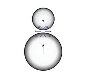
  $r$ is distance from the axis, as shown in figure 1. The spheres are separated by a gap
  $h_0$, and
  $W=-\textrm {d}h_0/\textrm {d}t$ is the magnitude of the relative velocity of the spheres.

Figure 1. Schematic showing (a) two particles with radii and permeabilities  $a_i$ and
  $k_i$
$k_i$  $(i=1,2)$, respectively, with velocities
  $\pm \frac {1}{2}W$, and separated by a gap
  $h_0$; (b) profile of near-contact region between the particles showing cylindrical coordinate system.
The gap width  $h_0$ sets the length scale for gradients of the fluid velocity in the
  $z$-direction, and
  $W$ sets the scale for the magnitude of the fluid velocity in the
  $z$-direction. A distinct lateral length scale
  $L$ describes variations of the fluid velocity in the radial direction,
 \begin{equation} a\gg L\gg h_0 . \end{equation}
Under this assumption, the radial velocity scale is  $W L/h_0$ according to the continuity equation, and, by the Navier–Stokes equations, the characteristic pressure in the gap is given by
 \begin{equation} p_c \sim \mu W a^{3} L^{{-}4} . \end{equation}
Close to the symmetry axis, the profile of the gap between spherical particles is approximately parabolic,
 \begin{equation} h=h_0+\frac{r^{2}}{2 a} , \end{equation}
where  $a_1$ and
  $a_2$ are the sphere radii, and
  $a$ is the reduced radius (
 $a^{-1}=a_1^{-1}+a_2^{-1}$). This geometry suggests the lateral length scale
 \begin{equation} L_0=\left(h_0 a\right)^{1/2} , \end{equation}
which lies in the range (2.1) required for lubrication theory and for the order of approximation of expansion (2.3), provided that  $(h_0/a)^{1/2}\ll 1$. For impermeable spheres, the appropriate lateral lubrication length scale is
  $L_0$.
The time scale for the near-contact motion is
 \begin{equation} t_0=\frac{h_0}{W} . \end{equation}
A second time scale enters the near-contact motion between permeable spheres given by  $t_k=h_0/j$, where
  $j$ is the magnitude of the flux according to Darcy's law,
  $j=k\boldsymbol {\nabla } \hat {p}/\mu$ and
  $\boldsymbol {\nabla }\hat {p}$ is the intraparticle pressure gradient. Inside the permeable particles, pressure variations are the same order of magnitude in the radial and axial directions, and by the continuity of the pressure across the particle surface,
  $\boldsymbol {\nabla }\hat {p}\sim p_c/L$, where
  $p_c$ is the characteristic pressure in the gap between the particles. Combining these estimates with the scaling (2.2) and taking
  $L=L_0$ for the lateral length scale, yields the second time scale,
 \begin{equation} t_k=t_0 K^{{-}1}\left(\frac{L_0}{a}\right)^{5} . \end{equation}
Here,  $K=k/a^{2}$ is the dimensionless permeability. This result can be re-written as
 \begin{equation} \frac{t_k}{t_0}=\left(\frac{L_0}{L_k}\right)^{5} , \end{equation}
thereby defining a second lateral length scale,
 \begin{equation} L_k= a K^{1/5} . \end{equation}
Herein, small permeabilities,
 \begin{equation} K^{1/5}\ll 1 \end{equation}
are assumed so that  $L_k$ lies in the required range (2.1). (Moreover,
  $L_k$ exceeds the pore scale,
  $a K^{1/2}$, as required for the use of Darcy's law.)
The ratio of the above time or length scales defines a parameter  $q$ that characterizes the near-contact motion of permeable spheres,
 \begin{equation} q = (t_k/t_0)^{2/5}=(L_0/L_k)^{2}=\frac{h_0}{a}K^{{-}2/5} . \end{equation}
The shortest of the two time scales, and correspondingly the longest of the two length scales, controls the near-contact motion. For  $q \gg 1$, near-contact motion results primarily by fluid flow from the gap between the particles; for
  $q \ll 1$, near-contact motion results primarily from fluid flow into the permeable particles. The cross-over between these regimes occurs for
  $q=O(1)$.
The last expression on the right side of (2.10), obtained by inserting (2.4) and (2.8), indicates that the parameter  $q$ can be interpreted as a re-scaled gap width, i.e.
  $h_0/a$ normalized by
  $K^{2/5}$. This interpretation indicates that particle permeability becomes important for
  $h_0/a < K^{2/5}$. Under the assumption of small permeabilities (2.9), this transition occurs within the lubrication regime.
Given that the force driving the near-contact motion is balanced by the pressure in the lubrication region,  $F\sim p_c L^{2}$, and using (2.2) yields
 \begin{equation} F \sim \mu W a^{3} L^{{-}2} , \end{equation}
where  $L= \max (L_0, L_k)$. Taking
  $L=L_0$ recovers the classical singular lubrication resistance that characterizes the near-contact motion of impermeable spheres,
 \begin{equation} F\sim \mu W a^{2} h_0^{{-}1} , \end{equation}
and thus  $W\sim F(\mu a)^{-1}(h_0/a)$, indicating that the gap decays exponentially in time under the action of a constant force but contact does not occur. Ultimately, however, when the gap between the particles diminishes so that
  $\max (L_0, L_k)=L_k$, the non-singular, gap-independent force is
 \begin{equation} F\sim \mu a W K^{{-}2/5} , \end{equation}
according to (2.8) and (2.11). Here,  $W\sim F(\mu a)^{-1}K^{2/5}$, indicating that the relative velocity between permeable spheres approaches a constant value under the action of a constant force and contact occurs in finite time.
3. Lubrication formulation
Here, a lubrication formulation is presented for the near-contact motion of two permeable particles. The formulation accounts for the fluid flux  $j$ into the particles described by Darcy's law with the Beavers–Joseph boundary condition to account for the slip at the interface of a permeable medium. The particle size ratio is arbitrary; hence the limiting case of a particle approaching a half-space is recovered. As shown below, it is convenient to define the mean permeability
 \begin{equation} k=\tfrac{1}{2}(k_1+k_2) \end{equation}
to accommodate particles with distinct permeabilities. Accordingly, the dimensionless mean permeability is defined as
 \begin{equation} K=k/a^{2} . \end{equation}
 Two sets of dimensionless lubrication variables are defined corresponding to the choice of characteristic length: (a) classical lubrication variables for impermeable spheres defined in terms of the length scale  $L_0$,
 \begin{equation} \bar{r}=\frac{r}{L_0} ,\quad \bar{z}=\frac{z a}{L_0^{2}} ,\quad \bar{v}=\frac{vL_0}{Wa} ,\quad \bar{w}=\frac{w}{W},\quad \bar{p}=\frac{p L_0^{4}}{\mu W a^{3}} ,\quad \bar{j}=\frac{j}{W}q^{5/2}, \end{equation}
and (b) permeable-sphere lubrication variables defined in terms of the length scale  $L_k$,
 \begin{equation} \tilde{r}=\frac{r}{L_k} ,\quad \tilde{z}=\frac{z a}{L_k^{2}} ,\quad \tilde{v}=\frac{vL_k}{Wa},\quad \tilde{w}=\frac{w}{W} ,\quad \tilde{p}=\frac{p L_k^{4}}{\mu W a^{3}} ,\quad \tilde{j}=\frac{j}{W} . \end{equation}
Here,  $(r,z)$ is the cylindrical coordinate system defined in figure 1;
  $v$ and
  $w$ are the corresponding radial and axial components of the fluid velocity in the lubrication region. The dimensionless axial velocity is unaffected by the characteristic length because it is non-dimensionalized by relative velocity of the particles,
  $W$. The parameter
  $q$ is defined by (2.10). The dimensionless intraparticle flux
  $\bar {j}$ or
  $\tilde {j}$ in (3.3a–f)–(3.4a–f) is obtained using the characteristic magnitude,
 \begin{equation} j\sim\frac{k}{\mu}\frac{p_c}{L} , \end{equation}
where  $p_c$ is given by (2.2) and
  $L$ is given by
  $L_0$ or
  $L_k$, respectively.
3.1. Formulation in classical lubrication variables
The formulation is presented here in terms of the classical lubrication variables for impermeable spheres (3.3a–f). The resulting leading-order lubrication equation that governs the pressure in the near-contact region between permeable particles is
 \begin{align} 2 q^{{-}5/2}\, \bar{j}[\bar{p}]-1=\frac{1}{\bar{r}}\frac{\textrm{d}}{\textrm{d}\bar{r}}\left[\bar{r}\frac{\textrm{d}\bar{ p}}{\textrm{d}\bar{r}}\frac{\bar{h}^{3}}{12}\, g\left(\frac{\hat{\alpha}_1}{q\bar{ h}},\frac{\hat{\alpha}_2}{q\bar{h}}\right) \right],\quad \left.\frac{\textrm{d}\bar{p}}{\textrm{d}\bar{ r}}\right\vert_{\bar{r}=0}=0 ,\quad \lim_{\bar{r}\to \infty}\bar{p}(\bar{r})=0 , \end{align}
where the dimensionless form of the gap profile (2.3) is
 \begin{equation} \bar{h}=1+\frac{\bar{r}^{2}}{2} , \end{equation}
and  $2\bar {j}$ is the total flux of fluid into the particles. The following paragraphs extend the description of the terms appearing in (3.6a–c).
The tangential fluid velocity on the permeable particle surfaces obeys the Beavers–Joseph slip-velocity boundary condition  $v_s=\alpha k^{1/2} \mu ^{-1} \tau$, where
  $\tau$ is the tangential stress on the particle surface, and
  $\alpha$ is the slip coefficient (Beavers & Joseph Reference Beavers and Joseph1967; Saffman Reference Saffman1971). The slip parameters
  $\hat {\alpha }_i$ (
 $i=1,2$) that appear in (3.6a–c) are defined as
 \begin{equation} \hat{\alpha}_i= \alpha_i K_i^{1/2} K^{{-}2/5} , \end{equation}
where  $\alpha _i$ and
  $K_i=k_i/a^{2}$, respectively, are the slip coefficient and dimensionless permeability of particle
  $i$, and
  $K$ is the dimensionless mean permeability (3.2). The radial velocity profile is derived in Appendix B, where it is shown that the term multiplying
  $\bar {r}$ in the square brackets on the right side of (3.6a–c) is the radial flux (B5) recast in dimensionless variables (3.3a–f). The function
  $g$, derived in Appendix B, accounts for velocity slip on the particle surfaces and is given by
 \begin{equation} g(x_1, x_2)= \frac{1+4x_1+4x_2+12 x_1 x_2}{1+x_1+x_2} . \end{equation}
For particles with equal slip parameters,  $\hat {\alpha }_2=\hat {\alpha }_1$, (3.9) reduces to
 \begin{equation} g=1+6 x_1 . \end{equation}
The total flux of fluid into the particle surfaces is given by Darcy's law,
 \begin{equation} 2 j=\frac{k_1}{\mu}\frac{\partial \hat{p}_1}{\partial n}+\frac{k_2}{\mu}\frac{\partial \hat{p}_2}{\partial n} , \end{equation}
where  $\hat {p}_1$ and
  $\hat {p}_2$ are the intraparticle pressure fields that satisfy Laplace's equation, the gradients are evaluated on the particle surfaces and
  $n$ is in the outward normal direction. Continuity of the pressure field across the particle surfaces imposes the length scale
  $L$ on the intraparticle pressure fields. Given that
  $L\ll a$, the intraparticle pressures decay quadratically to zero away from the particle surfaces according to (A5). Thus, to leading order, the intraparticle pressure fields obey Laplace's equation in a semi-infinite region.
Moreover, the intraparticle pressure fields  $\hat {p}_1$ and
  $\hat {p}_2$ are equal because they are forced only by the radial pressure distribution in the gap and pressure variations across the gap (i.e.
  $z$-direction) are negligible according to the lubrication approximation. Thus, (3.11) simplifies to
 \begin{equation} j=\frac{k}{\mu}\frac{\partial \hat{p}}{\partial n} , \end{equation}
indicating that the total intraparticle flux depends only on the mean permeability (3.1).
As shown in Appendix A, the pressure gradient at the particle surfaces can be expressed as a boundary integral of radial pressure variations in the gap between the particles. Inserting the result given by (A8)–(A10) into (3.12) and non-dimensionalizing, yields the flux,
 \begin{equation} \bar{j}[\bar{p}](\bar{r})={-}\int_{0}^{\infty} \frac{1}{r'}\frac{\textrm{d}}{\textrm{d}r'}\left(r'\frac{\textrm{d}\bar{ p}}{\textrm{d}r'}\right)\phi(r'/\bar{r})\,\textrm{d}r' . \end{equation}
This result demonstrates the non-local character of the lubrication problem for permeable particles, i.e. the local flux into the particles depends on the pressure distribution over the entire lubrication region.
Inserting (3.13) into (3.6a–c) defines an integro-differential equation for the pressure in the lubrication region between the particles. The classical description for impermeable spheres is recovered for  $q\to \infty$ but the formulation is singular for
  $q\to 0$, corresponding to particles in contact. An alternate formulation that is non-singular for particles in contact is obtained using the permeable-sphere lubrication variables.
3.2. Formulation in permeable-sphere lubrication variables
In terms of permeable-sphere lubrication variables (3.4a–f), (3.6a–c) and (3.13) become
 \begin{equation} 2\,\tilde{j}[\tilde{p}]-1=\frac{1}{\tilde{r}}\frac{\textrm{d}}{\textrm{d}\tilde{r}}\left[\tilde{r} \frac{\textrm{d}\tilde{p}}{\textrm{d}\tilde{r}}\frac{\tilde{h}^{3}}{12}\, g\left(\frac{\hat{\alpha}_1}{\tilde {h}},\frac{\hat{\alpha}_2}{\tilde{h}} \right) \right] ,\quad \left.\frac{\textrm{d}\tilde{p}}{\textrm{d}\tilde{ r}}\right\vert_{\tilde{r}=0}=0 ,\quad \lim_{\tilde{r}\to \infty}\tilde{p}(\tilde{r})=0 , \end{equation}
and
 \begin{equation} \tilde{j}[\tilde{p}](\tilde{r})={-}\int_{0}^{\infty} \frac{1}{r'}\frac{\textrm{d}}{\textrm{d}r'}\left(r'\frac{\textrm{d}\tilde{p}}{\textrm{d}r'}\right)\phi(r'/\tilde{r})\,\textrm{d}r' . \end{equation}
In these variables, the parameter  $q$ appears only in the dimensionless gap profile,
 \begin{equation} \tilde{h}=q+\frac{\tilde{r}^{2}}{2} . \end{equation}
The solution for particles in contact is obtained by setting  $q=0$.
3.3. Near-contact motion of a spherical drop and a permeable particle
The lubrication formulation for the near-contact motion between a spherical drop with a fully mobile interface and a particle with permeability  $k_1$ and slip coefficient
  $\alpha _1$ is obtained in the limit
  $\alpha _2\to \infty$ (Barnocky & Davis Reference Barnocky and Davis1989). In this limit, (3.9) reduces to
 \begin{equation} g=4(1+3x_1) , \quad \mbox{drop} . \end{equation}
Given that the drop is impermeable,  $k=\frac {1}{2}k_1$. Accordingly, the dimensionless lubrication formulations (3.6a–c) and (3.14a–c) for this problem are
 \begin{align} 2 q^{{-}5/2}\, \bar{j}[\bar{p}]-1=\frac{1}{\bar{r}}\frac{\textrm{d}}{\textrm{d}\bar{r}}\left[\bar{r} \frac{\textrm{d}\bar{p}}{\textrm{d}\bar{r}}\frac{\bar{h}^{3}}{3} \left(1+3\frac{\hat{\alpha}_1}{q\bar{h}}\right) \right] ,\quad \left.\frac{\textrm{d}\bar{p}}{\textrm{d}\bar{r}}\right\vert_{\bar{r}=0}=0 ,\quad \lim_{\bar{r}\to \infty}\bar{p}(\bar{r})=0 , \end{align}
and
 \begin{equation} 2\, \tilde{j}[\tilde{p}]-1=\frac{1}{\tilde{r}}\frac{\textrm{d}}{\textrm{d}\tilde{r}}\left[\tilde{r} \frac{\textrm{d}\tilde{p}}{\textrm{d}\tilde{r}}\frac{\tilde{h}^{3}}{3} \left(1+3\frac{\hat{\alpha}_1}{\tilde{ h}}\right) \right] ,\quad \left.\frac{\textrm{d}\tilde{p}}{\textrm{d}\tilde{r}}\right\vert_{\tilde{r}=0}=0 ,\quad \lim_{\tilde{r}\to \infty}\tilde{p}(\tilde{r})=0 , \end{equation}
where  $\bar {h}$,
  $\bar {j}$,
  $\tilde {j}$ and
  $\tilde {h}$ are given by (3.7), (3.13), (3.15) and (3.16), respectively.
Although these equations differ from (3.6a–c), (3.13) and (3.14a–c), (3.15), their solutions can be derived from the latter for the case of two permeable particles with equal slip parameters using the following transformation,
 \begin{equation} L_k\to 2^{2/5} L_k' , \quad p\to \tfrac{1}{4} p' ,\quad \hat{\alpha}_1\to 2^{1/5}\hat{\alpha}' . \end{equation}
Under this transformation, the dimensionless variables and parameters undergo the transformations,
 $$\begin{gather} \bar{r}\to \bar{r}' ,\quad \bar{h}\to \bar{h}' , \quad \bar{p}\to \tfrac{1}{4}\bar{p}' , \end{gather}$$
 $$\begin{gather}\tilde{r}=2^{{-}2/5}\tilde{r}' ,\quad\tilde{h}= 2^{{-}4/5}\tilde{h}' , \quad \tilde{p}\to 2^{{-}2/5} \tilde{p}' , \end{gather}$$
 $$\begin{gather}q\to 2^{{-}4/5} q' . \end{gather}$$
Inserting transformations (3.20a–c)–(3.23) into (3.18a–c)–(3.19a–c) yields (3.6a–c) and (3.14a–c), with  $g$ given by (3.10), that describe the near-contact motion of two particles with parameters
  $q'$ and
  $\hat {\alpha }_1=\hat {\alpha }_2=\hat {\alpha }'$.
Embedded in formula (3.17) are three assumptions: (i) surface tension gradients, i.e. Marangoni stresses, are absent; (ii) tangential stresses in the gap dominate viscous stresses associated with the fluid flow inside the drop; and (iii) capillary pressure dominates the lubrication pressure (2.2) so that drop deformation is negligible. Respectively, the latter two assumptions require 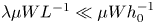 $\lambda \mu W L^{-1}\ll \mu W h_0^{-1}$ and
  $\mu W a^{3} L^{-4} \ll \gamma a^{-1}$, where
  $\gamma$ is the coefficient of interfacial tension,
  $\lambda \mu$ is the drop-phase viscosity, and
  $L=\max (L_0, L_k)$. Given definitions (2.4) and (2.8), these restrictions impose upper bounds on the viscosity ratio,
  $\lambda$, and Bond number,
  $Bo=F/(\gamma a)$,
 \begin{equation} \lambda\ll \left(a/h_0\right)^{1/2} \max\left[1,q^{{-}1/2}\right] , \quad Bo \ll K^{2/5}\max\left[1,q^{2}\right] . \end{equation}
Under conditions described by (3.24a), the system is independent of viscosity ratio. Provided that  $Bo \ll K^{2/5}$, the neglect of drop deformation is uniformly valid in gap. This contrasts with the usual near-contact motion of drops with impermeable surfaces where deformation always becomes important at sufficiently small gaps.
4. Results
The results presented in §§ 4.1–4.4 are for the case of no-slip boundary conditions on the surfaces of permeable particles. Under no-slip conditions, only the mean permeability (3.1) enters the problem and the behaviour of the system is characterized by a single parameter,  $q$. The effect of velocity slip at the surface of permeable particles is considered in § 4.5. Extension of the results to describe the lubrication resistance for drops and permeable particles is presented in § 4.6.
4.1. Limiting asymptotic results
4.1.1. Large and small values of  $q$
$q$

Large  $q$ describes conditions where the effect of permeability on near-contact motion is weak. For
  $q\gg 1$, (3.6a–c) can be solved by a regular perturbation to obtain an expansion for the pressure in integer powers of
  $q^{-5/2}$,
 \begin{equation} \bar{p}(\bar{r}, q) = \bar{p}^{(0)}(\bar{r})+ q^{{-}5/2}\, \bar{p}^{(1)}(\bar{r}) +O( q^{{-}5}), \end{equation}
and
 \begin{equation} \bar{j}(\bar{r})=\bar{j}^{(0)}(\bar{r}) +O( q^{{-}5/2}) . \end{equation}
The leading-order pressure distribution is
 \begin{equation} \bar{p}^{(0)}(\bar{r})=\frac{3}{\bar{h}^{2}(\bar{r})}, \end{equation}
corresponding to impermeable spheres, and the leading-order intraparticle flux is derived from it,
 \begin{equation} \bar{j}^{(0)}(\bar{r})={-}\int_{0}^{\infty} \frac{1}{r'}\frac{\textrm{d}}{\textrm{d}r'}\left(r'\frac{\textrm{d}\bar{ p}^{(0)}}{\textrm{d}r'}\right)\phi(r'/\bar{r})\,\textrm{d}r' . \end{equation}
The first-order perturbation problem for the pressure distribution is
 \begin{equation} \frac{1}{\bar{r}}\frac{\textrm{d}}{\textrm{d}\bar{r}}\left[\bar{r} \frac{\textrm{d}\bar{p}^{(1)}}{\textrm{d}\bar{r}}\frac{\bar{ h}^{3}}{12}\right]=2\, \bar{j}^{(0)}(\bar{r}) ,\quad \left.\frac{\textrm{d}\bar{p}^{(1)}}{\textrm{d}\bar{ r}}\right\vert_{\bar{r}=0}=0 ,\quad \lim_{\bar{r}\to \infty}\bar{p}^{(1)}(\bar{r})=0 , \end{equation}
where  $\bar {j}^{(0)}(\bar {r})$ is given by (4.4). Solving this boundary-value problem and integrating by parts yields,
 \begin{equation} \bar{p}^{(1)}(\bar{r})=12\left[\int^{\infty}_{\bar{r}} u(r') \bar{j}^{(0)}( r') r' \,\textrm{d} r' + u(\bar{r}) \int^{\bar{r}}_{0} \bar{j}^{(0)}( r') r' \,\textrm{d} r' \right] , \end{equation}
where
 \begin{equation} u(\bar{r})=\frac{2 \bar{h}(\bar{r})+1}{2\bar{h}^{2}(\bar{r})}+\log\left(\frac{\bar{h}(\bar{ r})-1}{\bar{h}(\bar{r})}\right) . \end{equation}
 Small  $q$ describes conditions where the intraparticle flux qualitatively affects near-contact motion. For
  $q\ll 1$, the pressure has an expansion in integer powers of
  $q$ that can be derived by solving (3.14a–c) with a regular perturbation,
 \begin{equation} \tilde{p}(\tilde{r}, q)=\tilde{p}^{(0)}(\tilde{r})+O( q) , \end{equation}
where  $\tilde {p}^{(0)}(\tilde {r})$ is obtained by solving (3.14a–c) with
  $q=0$, corresponding to particles in contact.
4.1.2. Far-field pressure and intraparticle flux
By the analysis presented in Appendix C, the far-field flux and pressure distributions are
 $$\begin{gather} \bar{j}(\bar{r})={-}3\,\bar{f}(q) \, \bar{r}^{{-}3} +O(\bar{r}^{{-}5}) , \end{gather}$$
 $$\begin{gather}\bar{p}(\bar{r}) -\bar{p}^{(0)}(\bar{r})={-}\frac{576}{7}\bar{f}(q)\, \bar{r}^{{-}7} q^{{-}5/2}+O(\bar{r}^{{-}9}\log\bar{r}) , \end{gather}$$
where  $\bar {p}^{(0)}(\bar {r})$ is the pressure distribution corresponding to impermeable spheres (4.3), and
  $\bar {f}$ is the dimensionless lubrication resistance (4.14a) that depends on the pressure distribution over the entire lubrication region, reflecting the intrinsically non-local character of the problem.
4.1.3. Near-field intraparticle flux
The intraparticle flux is largest near the symmetry axis,  $r\ll \max (L_0, L_k)$. For
  $q\gg 1$, the near-field intraparticle flux is
 \begin{equation} 2 \bar{j}(\bar{r}) = \frac{9 {\rm \pi}}{2\sqrt{2}}-O(\bar{r}^{2} q^{{-}7/2}), \end{equation}
which is obtained by inserting the leading-order pressure profile (4.3) and the Green's function expansion (A14) into boundary integral (3.13). For  $q\ll 1$, the near-field flux is obtained by expanding (3.14a–c) to yield
 \begin{equation} 2 \tilde{j}(\tilde{r}) = 1-O(\tilde{r}^{6})-O(q^{3}). \end{equation}
This result indicates that fluid near the symmetry axis flows into the particles rather than radially out of the gap between them.
4.2. Pressure and flux distributions
The pressure and intraparticle flux distributions in the lubrication region are depicted in figures 2 and 3. These results were obtained by numerical solution of (3.6a–c) and (3.14a–c). The large- $q$ expansions (4.1)–(4.2) are shown for the case
  $q=5$.

Figure 2. Pressure distribution between permeable particles with no-slip boundary conditions,  $q$ as indicated; classical (a) and permeable-sphere (b) lubrication variables; two-term large-
 $q$ expansion (4.1) for
  $q=5$ (dashed line); inset: curves depicting
  $\bar {p}^{(0)}(\bar {r})-\bar {p}(\bar {r})$, far-field expansion (4.10) (dash-dotted lines).

Figure 3. Intraparticle flux distribution into permeable particles with no-slip boundary conditions and  $q$ as indicated in terms of classical (a) and permeable-sphere (b) lubrication variables; leading-order large-
 $q$ expansion (4.2) (dash-dotted line) in (a) and curve for
  $q=5$ (dashed line) in (b); insets show
  $2\bar {j}\bar {r}^{3}$ (a) and
  $2\tilde {j}\tilde {r}^{3}$ (b) with far-field expansion (4.9) (dashed lines).
The inset of figure 2 shows that the pressure field is insensitive to particle permeability in the far-field, consistent with (4.10). The maximum intraparticle flux observed in figure 3(a) for  $q\to \infty$ agrees with the prediction value (4.11), and the intraparticle flux profile corresponding to
  $q=0$ in figure 3(b) shows a broad region where fluid enters the permeable particle, consistent with (4.12). The results in figure 3 show regions of negative flux, i.e. fluid flux emerging from the particle interior. This observation is consistent with zero net flux into the particles (i.e.
  $\int _0^{\infty } j(r) r \,\textrm {d}r=0$), a consequence of the intraparticle pressure field obeying Laplace's equation, as shown in Appendix A. Non-monotonic flux distributions have been found in similar problems (Knox et al. Reference Knox, Duffy, McKee and Wilson2017).
4.3. Lubrication and contact force
Integrating the pressure distribution obtained by solving (3.6a–c) or (3.14a–c) yields the hydrodynamic force,  $F$,
$F$,
 \begin{equation} \frac{F}{6 {\rm \pi}\mu a W}=\left(\frac{a}{L}\right)^{2} f(q) , \end{equation}
where  $f$ is the dimensionless resistance coefficient corresponding to characteristic length
  $L$. Resistance coefficients
  $\bar {f}$ and
  $\tilde {f}$, corresponding to classical and permeable-sphere lubrication length scales
  $L_0$ and
  $L_k$, respectively, are defined
 \begin{equation} \bar{f}(q)=\tfrac{1}{3} \int_0^{\infty} \bar{p} \, \bar{r} \, \textrm{d}\bar{r} , \quad \tilde{f}(q)=\tfrac{1}{3} \int_0^{\infty} \tilde{p} \, \tilde{r} \, \textrm{d}\tilde{r} . \end{equation}
The resistance coefficients are related,  $\bar {f}=q\tilde {f}$, according to (2.10) and (4.13). Figure 4 shows the resistance coefficients as functions of
  $q;$ dashed lines depict the limiting formulas given below.


Inserting the pressure distribution for impermeable spheres (4.3) into (4.14a) yields  $\bar {f}=1$, corresponding to the classical Reynolds lubrication force
  $F_0=6{\rm \pi} \mu a^{2} W/h_0$. Retaining the next term in the large-
 $q$ expansion (4.1) yields
 \begin{equation} \bar{f}(q)=1-c q^{{-}5/2}+O(q^{{-}5}) , \end{equation}
where  $c\doteq 1.8402$. According to definition (2.10), the result implies that the lubrication force between particles is reduced in proportion to their mean permeability, i.e.
  $\bar {f}=1-c k a^{1/2}h_0^{-5/2}$.
Integrating the solution of (3.14a–c) in formula (4.14b) yields
 \begin{equation} \tilde{f}(q)=\tilde{f}_c^{(0)} - D q+ O(q^{2}) \end{equation}
for  $q \ll 1$, where
  $\tilde {f}^{(0)}_c$ is the contact resistance,
 \begin{equation} \tilde{f}_c^{(0)}\doteq 0.7507 , \end{equation}
corresponding to  $q=0$, and
  $D\doteq 0.224$ is the first-order correction. By contrast to the singular lubrication force between impermeable spheres, the lubrication force between permeable spheres with mean dimensionless permeability
  $K$ attains a finite maximum value at contact,
 \begin{equation} F_c=6{\rm \pi}\mu a W K^{{-}2/5}\tilde{f}_c^{(0)} , \end{equation}
consistent with the scaling (2.13).
4.3.1. Permeable and impermeable particles
The near-contact motion between a particle with permeability  $k_1$ and an impermeable particle (
 $k_2=0$) is interesting because it describes the capture of impermeable particles at the interface of a porous medium (e.g. filter thicker than
  $L_k$) and the near-contact motion of a permeable particle towards an impermeable wall. This case is encompassed by the above results given that only the mean permeability
  $k=\frac {1}{2}k_1$ enters the formulation under no-slip boundary conditions.
4.4. Contact time
Here, the contact time is calculated for two permeable particles under the action of a constant force along their centreline. The contact time  $t_c$ for two particles brought together from an arbitrary surface-to-surface separation
  $h_\infty$ has two contributions,
 \begin{equation} \bar{t}_c=\bar{t}_\infty+\bar{t}_0 , \end{equation}
where the overbar denotes time normalized by the Stokes time  $6{\rm \pi} \mu a^{2}/F$. The time
  $\bar {t}_\infty$ represents the time required to bring the particles from the initial separation
  $h_\infty$ to a gap
  $h_0$ that lies in the range
 \begin{equation} K^{2/5}\ll \frac{h_0}{a}\ll 1 , \end{equation}
and  $\bar {t}_0$ is the time required for the gap to decrease from
  $h_0$ to contact in the lubrication regime. For
  $h_0$ in the range (4.20),
  $q_0=(h_0/a)K^{-2/5}\gg 1$, thus
  $\bar {t}_\infty$ is insensitive to particle permeability and can be accurately approximated by the time required for impermeable spheres to move from their initial separation
  $h_\infty$ to a separation
  $h_0$. Accordingly,
 \begin{equation} \bar{t}_\infty=C_\infty-\log(h_0/a) , \end{equation}
where  $C_\infty$ is determined by the hydrodynamics of impermeable spheres and depends only on the initial separation. By contrast,
  $\bar {t}_0$ is sensitive to the particle permeability. Taking
  $W=-\textrm {d}h_0/\textrm {d}t$ and integrating (4.13) yields
 \begin{equation} \bar{t}_0(q_0)= \int_0^{q_0} \frac{\bar{f}(q)}{q}\,\textrm{d}q . \end{equation}
This calculation can be re-written to isolate the dependence on  $q_0$, given that
  $q_0\gg 1$ and
  $\bar {f}\to 1$ for large
  $q$. Rewriting (4.22) and combining with (4.19), (4.21), and (2.10) yields a formula for the contact time
 \begin{equation} \bar{t}_c=C_\infty - \log\left( C_0 K^{2/5}\right) + O(K) , \end{equation}
where
 \begin{equation} C_0=\exp\left[-\int_0^{1} \frac{\bar{f}(q)}{q}\,\textrm{d}q - \int_1^{\infty} \frac{\bar{f}(q)-1}{q}\,\textrm{d}q\right]\doteq 0.7224 . \end{equation}
Accordingly, the contact time between permeable spheres under the action of a constant force is finite, consistent with the discussion below (2.13).
4.4.1. Rough particles
The contact time for impermeable spheres with small amplitude roughness  $\delta \ll a$ is
 \begin{equation} \bar{t}_c= C_\infty-\log(\delta/a) , \end{equation}
where  $C_\infty$ depends only on the initial separation,
  $h_\infty$, as defined above. This result is obtained by assuming that hydrodynamic interactions are identical to smooth spheres, except that contact occurs at a finite separation,
  $\delta$ (Smart & Leighton Reference Smart and Leighton1989; Da Cunha & Hinch Reference Da Cunha and Hinch1996). This simple model for roughness describes particles with a sparse coating of asperities (Jenkins & Koenders Reference Jenkins and Koenders2005).
An equivalent roughness,  $\delta _{eq}$, can be defined as the roughness amplitude that yields the same contact time for rough and permeable spheres under the action of a constant force. Equating the contact time predicted by (4.23) and (4.25) for permeable and rough particles, respectively, yields
 \begin{equation} \delta_{eq}/a= C_0K^{2/5} , \end{equation}
where  $C_0$ has the numerical value given in (4.24).
4.5. Effect of velocity slip
Here, the effect of velocity slip at the surfaces of the permeable particles is explored. Extensions of the large- $q$ and far-field expansions for finite slip are presented in §§ 4.5.1 and 4.5.2. The effect of slip on the contact force and contact time are presented in §§ 4.5.3 and 4.5.5. The connection to the problem of impermeable particles with slip-velocity boundary conditions is discussed in § 4.5.4.
4.5.1. Large-q expansion with finite slip
Solving (3.6a–c) by a regular perturbation for  $q\gg 1$ with finite slip requires an expansion of (3.9) for small values of its arguments. The resulting expansion is
 \begin{equation} \bar{p}(\bar{r}, q, \hat{\alpha}_{1},\hat{\alpha}_{2}) = \bar{p}_{0}(\bar{r}, q)+\bar{p}_{\alpha}(\bar{r}, q, \hat{\alpha}_{1},\hat{\alpha}_{2}) , \end{equation}
where  $\bar {p}_{0}(\bar {r}, q)$ is the expansion (4.1) for no-slip conditions, and
  $\bar {p}_{\alpha }(\bar {r}, q, \hat {\alpha }_{1},\hat {\alpha }_{2})$ is the expansion
 \begin{align} \bar{p}_{\alpha}(\bar{r}, q, \hat{\alpha}_{1},\hat{\alpha}_{2}) &= q^{{-}1} \, \bar{p}^{(1)}_{\alpha}(\bar{r}, \hat{\alpha}_{1},\hat{\alpha}_{2})+q^{{-}2}\, \bar{p}^{(2)}_{\alpha}(\bar{r}, \hat{\alpha}_{1},\hat{\alpha}_{2})\notag\\ &\quad + q^{{-}3}\, \bar{p}^{(3)}_{\alpha}(\bar{r}, \hat{\alpha}_{1},\hat{\alpha}_{2})+O(q^{{-}4}) , \end{align}
where
 $$\begin{gather} \bar{p}^{(1)}_{\alpha}(\bar{r}, \hat{\alpha}_{1},\hat{\alpha}_{2})={-}\frac{12}{\bar{h}^{3}} \hat{\alpha}_{m}, \end{gather}$$
 $$\begin{gather}\bar{p}^{(2)}_{\alpha}(\bar{r}, \hat{\alpha}_{1},\hat{\alpha}_{2})= \frac{18}{\bar{h}^{4}}(4\hat{\alpha}_{m}^{2}-\hat{\alpha}_{m} \hat{\alpha}_{r}) , \end{gather}$$
 $$\begin{gather}\bar{p}^{(3)}_{\alpha}(\bar{r}, \hat{\alpha}_{1},\hat{\alpha}_{2})={-}\frac{144}{5}\frac{1}{\bar{h}^{5}}(16\hat{\alpha}_{m}^{3}-7\hat{\alpha}_{m}^{2} \hat{\alpha}_{r}) . \end{gather}$$
Here,
 \begin{equation} \hat{\alpha}_{m} = \tfrac{1}{2}\left(\hat{\alpha}_1+ \hat{\alpha}_2\right) \end{equation}
and
 \begin{equation} \hat{\alpha}_{r}^{{-}1} = \tfrac{1}{2}\left(\hat{\alpha}_1^{{-}1}+ \hat{\alpha}_2^{{-}1}\right) \end{equation}
are the mean and reduced slip parameters, respectively, both assumed to be  $O(1)$. The leading-order intraparticle flux (4.4) is unaffected by slip for
  $q\gg 1$.
Inserting expansion (4.27) into (4.14a) yields
 \begin{equation} \bar{f}(q, \hat{\alpha}_{1},\hat{\alpha}_{2}) = \bar{f}_{0}(q)+\bar{f}_{\alpha}(q, \hat{\alpha}_{1},\hat{\alpha}_{2}) , \end{equation}
where  $\bar {f}_{0}(q)$ is given by expansion (4.15), and
 \begin{equation} \bar{f}_{\alpha}(q, \hat{\alpha}_{1},\hat{\alpha}_{2}) = q^{{-}1} \, \bar{f}^{(1)}_{\alpha}(\hat{\alpha}_{1},\hat{\alpha}_{2})+q^{{-}2}\, \bar{f}^{(2)}_{\alpha}(\hat{\alpha}_{1},\hat{\alpha}_{2})+q^{{-}3}\, \bar{f}^{(3)}_{\alpha}(\hat{\alpha}_{1},\hat{\alpha}_{2}) +o(q^{{-}3}), \end{equation}
with
 $$\begin{gather} \bar{f}^{(1)}_{\alpha}(\hat{\alpha}_{1},\hat{\alpha}_{2})={-}2\hat{\alpha}_{m} , \end{gather}$$
 $$\begin{gather}\bar{f}^{(2)}_{\alpha}(\hat{\alpha}_{1},\hat{\alpha}_{2})= 2(4\hat{\alpha}_{m}^{2}-\hat{\alpha}_{r}\hat{\alpha}_{m}) , \end{gather}$$
 $$\begin{gather}\bar{f}^{(3)}_{\alpha}(\hat{\alpha}_{1},\hat{\alpha}_{2})={-}\tfrac{12}{5}(16\hat{\alpha}_{m}^{3}-7\hat{\alpha}_{r}\hat{\alpha}_{m}^{2}) . \end{gather}$$
 These results indicate that the lubrication resistance for permeable and impermeable particles with slip-velocity boundary conditions coincide up to  $O(q^{-2})$; the effect of intraparticle flux enters at
  $O(q^{-5/2})$.
4.5.2. Far-field expansion with finite slip
At leading order, the far-field intraparticle flux is affected by velocity slip only through the resistance coefficient  $\bar {f}(q,\hat {\alpha }_{1},\hat {\alpha }_{2})$ and is thus given by (4.9). By the analysis presented in Appendix C, the far-field pressure distribution, extended for finite slip, is
 \begin{equation} \bar{p}(\bar{r}) - \bar{p}^{(0)}(\bar{r})={-}96q^{{-}1}\hat{\alpha}_{m}\bar{r}^{{-}6}-\tfrac{576}{7}\bar{f}(q,\hat{\alpha}_{1},\hat{\alpha}_{2})\, \bar{r}^{{-}7} q^{{-}5/2}+O(\bar{r}^{{-}8}) , \end{equation}
where  $\bar {p}^{(0)}(\bar {r})$ is the pressure distribution corresponding to impermeable spheres with no-slip boundary conditions (4.3). The result indicates that the effect of slip dominates the effect of permeability in the far field.
4.5.3. Contact force
The effect of slip on the contact resistance  $\tilde {f}_c$ is shown in figure 5 for two special cases
 \begin{equation} \left. \begin{array}{ll@{}} \hat{\alpha}_1=0 , & (1)\\ \hat{\alpha}_2=\hat{\alpha}_1 . & (2) \end{array}\right\} \end{equation}
Typically, case (1) describes the near-contact interaction of permeable and impermeable particles, discussed in § 4.3.1; case (2) typically describes near-contact interactions between particles with equal permeability and slip coefficients, according to the coupling between these parameters indicated by (3.8).


Figure 5 shows the numerical results obtained by solving (3.14a–c)–(3.15) with  $g$ given by
 \begin{equation} g=\frac{1+4x_2}{1+x_2} \end{equation}
for case (1), and by (3.10) for case (2).
For small values of the slip parameters, (3.9) is expanded for  $x_i\ll 1$ (
 $i=1,2$) to obtain
 \begin{equation} g=1+3(x_1+x_2)+O(x_i^{2}) . \end{equation}
This form indicates that the contact resistance,  $\tilde {f}_c(\hat {\alpha }_1,\hat {\alpha }_2)$, has the regular expansion
 \begin{equation} \tilde{f}_c(\hat{\alpha}_1,\hat{\alpha}_2)=\tilde{f}_c^{(0)}-A\hat{\alpha}_{m} + O(\hat{\alpha}_i^{2}) \end{equation}
for  $\hat {\alpha }_{m}\ll 1$, where
  $\hat {\alpha }_{m}$ is the mean slip parameter (4.30),
  $\tilde {f}_c^{(0)}$ is the contact resistance under no-slip conditions (4.17) and
  $A\approx 0.445$; the predictions are shown in figure 5.
For  $\hat {\alpha }_{r}\gg 1$, the contact force has the asymptotic form
 \begin{equation} \tilde{f}_c(\hat{\alpha}_1,\hat{\alpha}_2)= \frac{5}{9\hat{\alpha}_{r}} \left[\log\hat{\alpha}_{r}+B(\hat{\alpha}_2/\hat{\alpha}_1)\right]+O(\hat{\alpha}_{r}^{{-}2}\log\hat{\alpha}_{r}) , \end{equation}
according to the derivation given in Appendix D, where  $\hat {\alpha }_{r}$ is the reduced slip parameter (4.31) and the coefficient
  $B$ is obtained numerically. For equal slip parameters (i.e. case (2)),
  $B(1)\approx -0.17$ and the resulting asymptote is shown in figure 5.
A different situation arises for  $\hat {\alpha }_2\gg 1$ with
  $\hat {\alpha }_1=O(1)$ because
  $\hat {\alpha }_{r}=O(1)$ so that formula (4.40) does not apply. The limit
  $\hat {\alpha }_2\to \infty$ corresponds to the near-contact motion between a spherical drop and a permeable particle with slip parameter
  $\hat {\alpha }_1$ which has contact resistance
 \begin{equation} \tilde{f}_c^{(d)}(\hat{\alpha}_1)=2^{{-}6/5}\tilde{f}_c(2^{{-}1/5}\hat{\alpha}_1) , \end{equation}
according to (4.50b). Here,  $\tilde {f}_c(\hat {\alpha })$ is the contact resistance for permeable particles with equal slip parameters. Using this result and assuming the form (4.40) for the finite
  $\hat {\alpha }_2$ correction, yields
 \begin{align} \tilde{f}_c(\hat{\alpha}_1,\hat{\alpha}_2)=2^{{-}6/5}\tilde{f}_c(2^{{-}1/5}\hat{\alpha}_1)+\frac{A_1(\hat{\alpha}_1)}{\hat{\alpha}_2}\left[\log\hat{\alpha}_2+B_1(\hat{\alpha}_1)\right] +O(\alpha_2^{{-}2}\log\alpha_2) ,\quad \hat{\alpha}_2\gg 1 , \end{align}
where the coefficients  $A_1$ and
  $B_1$ are obtained numerically. For case (1) (i.e.
  $\alpha _1=0$), the coefficients have the values
  $A_1\approx 0.35$,
  $B_1\approx 0.43$, and
  $\tilde {f}_c(0)=\tilde {f}_c^{(0)}$ given by (4.17). The resulting asymptote is shown in figure 5.
4.5.4. Impermeable particles with slip-velocity boundary conditions
The classical first-order lubrication problem for the near-contact motion between impermeable particles with slip-velocity boundary conditions (Hocking Reference Hocking1973) is presented in Appendix E. Here, the results for permeable and impermeable particles with slip-velocity boundary conditions are compared for the case of particles with equal slip parameters.
The comparison requires taking the slip length in (E2) as
 \begin{equation} \lambda_s=\alpha k^{1/2} , \end{equation}
consistent with Beavers–Joseph boundary conditions (B2a,b), yielding the slip parameter for impermeable particles,
 \begin{equation} m=6\hat{\alpha}/q . \end{equation}
Inserting this definition into the small- $m$ expansion (E7) for the resistance
  $\bar {f}$ recovers the first 3 terms of the large-
 $q$ expansion (4.33)–(4.34) for permeable particles with equal slip parameters. Similarly, a small-
 $m$ expansion of the pressure (E3) recovers expansion (4.28)–(4.29) for the case of equal slip parameters. Also, the leading-order, far-field correction to the pressure,
  $\bar {p} - \bar {p}^{(0)}$, is the same for permeable and impermeable particles, as seen by inserting (4.44) into the expansion (E4) and comparing the result to (4.35) for equal slip parameters.
By contrast to the non-singular contact resistance for permeable particles,  $\tilde {f}(q,\hat {\alpha })=\tilde {f}_c(\hat {\alpha })$ for
  $q\to 0$, presented above in § 4.5.3, the resistance for impermeable particles with equal slip coefficients is log singular at contact,
 \begin{equation} \tilde{f}(q,\hat{\alpha})= \frac{1}{3\hat{\alpha}}\left[\log\left(\frac{6\hat{\alpha}}{q}\right)-1\right] ,\quad q\to 0 , \end{equation}
 The foregoing comparison shows that for large gaps,  $h_0/a \gg K^{2/5}$ (i.e.
  $q\gg 1$), permeable particles with slip can be approximated as impermeable particles with slip-velocity boundary conditions (O'Neill & Bhatt Reference O'Neill and Bhatt1991) but this approximation breaks down at small gaps,
  $h_0/a=O(K^{2/5})$, where the intraparticle flux becomes significant.
4.5.5. Contact time
In this section, the effect of velocity slip on the contact time between permeable particles under the action of a constant force is explored for the case of equal slip parameters  $\hat {\alpha }_{1}=\hat {\alpha }_{2}=\hat {\alpha }$. In this case, formula (4.23) becomes
 \begin{equation} \bar{t}_c=C_\infty - \log\left( C(\hat{\alpha}) K^{2/5}\right) +O(\hat{\alpha} K^{2/5}) , \end{equation}
where  $C(\hat {\alpha })$ describes the reduction in contact time resulting from velocity slip and is given by
 \begin{equation} C(\hat{\alpha})=\exp\left[-\int_0^{1} \frac{\bar{f}(q,\hat{\alpha})}{q}\,\textrm{d}q - \int_1^{\infty} \frac{\bar{f}(q,\hat{\alpha})-1}{q}\,\textrm{d}q\right] . \end{equation}
 The results in figure 6 show that  $C(\hat {\alpha })$ is approximately linear. For
  $\hat {\alpha } \ll 1$, the contact time (4.46) is controlled by particle permeability with
 \begin{equation} C(\hat{\alpha})=C_0+O(\hat{\alpha}), \end{equation}
where  $C_0$ has the numerical value reported in (4.24), and the constant of proportionality is approximately 1.15. For
  $\hat {\alpha } \gg 1$, the contact time is controlled by the slip velocity with
 \begin{equation} C(\hat{\alpha})=6 \textrm{e}^{{-}3/2}\hat{\alpha}+O(1), \end{equation}
according to (4.43) and (E11), and the constant is approximately 0.1. The equivalent roughness, defined by (4.26), can be extended for slip-velocity boundary conditions by inserting  $C(\hat {\alpha })$ in place of
  $C_0$.

The above results demonstrate that the classical non-integrable lubrication singularity is removed by either of two mechanisms: non-zero particle permeability, or non-zero slip velocity.
4.6. Permeable particles and drops with fully mobile interfaces
As shown in § 3.3, the results for a spherical drop with a fully mobile interface and a particle with permeability  $k_1$ and slip parameter
  $\hat {\alpha }_1$ can be obtained from the results for a pair of permeable particles using transformation (3.20a–c). Accordingly, the resistance functions
  $\bar {f}^{(d)}(\hat {\alpha }_1)$ and
  $\tilde {f}^{(d)}(\hat {\alpha }_1)$, for a spherical drop and a permeable particle, are given by
 \begin{equation} \bar{f}^{(d)}(q,\hat{\alpha}_1) =\tfrac{1}{4}\bar{f}(2^{4/5}q,2^{{-}1/5}\hat{\alpha}_1) , \quad \tilde{f}^{(d)}(q,\hat{\alpha}_1) =2^{{-}6/5}\tilde{f}(2^{4/5}q,2^{{-}1/5}\hat{\alpha}_1), \end{equation}
where  $\bar {f}(q,\hat {\alpha })$ and
  $\tilde {f}(q,\hat {\alpha })$ are the resistance functions for permeable particles with equal slip parameters.
Formulas (4.50a,b) extend the foregoing results for the lubrication resistance between permeable particles with equal slip parameters to the case of a spherical drop and a permeable particle with slip parameter  $\hat {\alpha }_1$. This includes the results for
  $\hat {\alpha }_1=0$ shown in figure 4 and (4.15)–(4.17), and, by setting
  $\hat {\alpha }_2=\hat {\alpha }_1$, also includes the results shown in figure 5 (curve 2) and (4.33) and (4.39)–(4.40).
According to formula (4.50a,b) and the analysis presented in §§ 4.4 and 4.5.5, the contact time between a spherical drop and a permeable particle is
 \begin{equation} \bar{t}_c=C'_\infty - \log\left( C'(\hat{\alpha}_1) K^{2/5}\right) , \end{equation}
where
 \begin{equation} C'(\hat{\alpha})=\left[C(2^{{-}1/5}\hat{\alpha})\right]^{1/4} . \end{equation}
Here,  $C(\hat {\alpha })$ is defined by (4.47) and plotted in figure 6. The parameter
  $C'_\infty$ is determined by the hydrodynamic interactions between a spherical drop and an impermeable sphere; it depends only on the initial separation and the viscosity ratio of the drop.
The contact time between a spherical drop and a rough particle is similarly modified  $\bar {t}_c= C'_\infty -\log (\delta /a)^{1/4}$ thus the equivalent roughness for a permeable particle is the same for its interaction with a spherical particle or a drop.
5. Comparison with previous work
In this section, the lubrication resistance obtained from this work is compared to prior bispherical-coordinate calculations by Burganos et al. (Reference Burganos, Michalopoulou, Dassios and Payatakes1992) and tangent-sphere-coordinate calculations by Sherwood (Reference Sherwood1988). The former calculations describe the motion of a permeable sphere toward an impermeable wall, the later describes the contact force of an impermeable sphere at the interface of a semi-infinite permeable medium.
The results presented in figure 7(a) show close agreement between the lubrication theory and the bispherical-coordinate calculations of Burganos et al. (Reference Burganos, Michalopoulou, Dassios and Payatakes1992). Errors of the lubrication approximation, defined by
 \begin{equation} \varDelta =\frac{F_{ex}-F_{lub}}{F_{ex}} , \end{equation}
are shown in figure 7(b), where  $F_{ex}$ is the exact result from bispherical-coordinate calculations (Burganos et al. Reference Burganos, Michalopoulou, Dassios and Payatakes1992), and
  $F_{lub}$ is the lubrication approximation. The results show that errors increase with gap width and permeability, as expected. When recast in terms of lubrication variables, the bispherical-coordinate calculations cluster onto a single curve in the regime where the lubrication theory is expected to apply (i.e.
  $(h_0/a)^{1/2}\ll 1$ and
  $K^{1/5}\ll 1$) as seen in figure 8. For a fixed value of the slip coefficient, the lubrication theory predicts a weak,
  $1/10$-power dependence on the permeability accordingly to (3.8), however, this is not discernible in the exact calculations.

Figure 7. Hydrodynamic force between a permeable sphere and an impermeable wall vs. gap,  $K_1=2K$ as indicated,
  $\alpha _1 =1$; (a) exact calculations (Burganos et al. Reference Burganos, Michalopoulou, Dassios and Payatakes1992)
  $\bullet$, lubrication theory (lines); (b) errors of lubrication approximation (5.1) (dashed straight lines between calculations
  $\bullet$).

Figure 8. Lubrication resistance  $\tilde {f}$ vs.
  $q$; exact calculations (Burganos et al. Reference Burganos, Michalopoulou, Dassios and Payatakes1992)
  $K_1=2K$ as indicated,
  $\alpha _1=1$; lubrication theory with
  $\hat {\alpha }_1=0.25$.
In terms of  $K=\frac {1}{2}K_1$, the contact force reported by Sherwood (Reference Sherwood1988) for an impermeable sphere in point contact with a permeable half-space, with
  $K_1^{1/5}\ll 1$ under no-slip boundary conditions, is given by (4.18) with coefficient
  $\tilde {f}_c^{(0)}= 0.27$; this is in contrast to the value
  $\tilde {f}_c^{(0)}\doteq 0.7507$ determined herein. We have been unable to reconcile this discrepancy (J.D. Sherwood, personal communication).
Supplementary material
Supplementary material is available at https://doi.org/10.1017/jfm.2021.588.
Funding
This work was supported by the National Science Foundation (grant number 1603806) and the Coordenação de Aperfeiçoamento de Pessoal de Nível Superior – Brasil (Capes) (Finance Code 001).
Declaration of interests
The authors report no conflict of interest.
Appendix A. Solution of intraparticle pressure in the lubrication region
Here, the normal derivative of the intraparticle pressure on the boundary of the particle surface is expressed as a boundary integral of the pressure distribution in the near-contact region. Dimensional variables are used. By the disparity of the length scales,  $L\ll a$, the intraparticle pressure
  $\hat {p}(r,z)$ obeys Laplace's equation
 \begin{equation} \nabla^{2}\hat{p}=0 \end{equation}
in a semi-infinite region, vanishes for  $z\to -\infty$, and matches the pressure,
  $p(r)$, in the lubrication gap on the boundary at
  $z=0$.
Hankel transformation of (A1) and boundary conditions yields
 \begin{equation} \frac{\textrm{d}^{2}\hat{P}}{\textrm{d}z^{2}}-\omega^{2} \hat{P}=0 ;\quad \hat{P}(\omega, 0)=\int_0^{\infty} \textrm{J}_0(\omega r) p(r) r \,\textrm{d}r ,\quad \hat{P}(\omega, -\infty)=0, \end{equation}
where  $\hat {P}(\omega ,z)=\int _0^{\infty } \textrm {J}_0(\omega r) \hat {p}(r,z) r \,\textrm {d}r$ is the Hankel-transformed pressure. The solution of the transformed problem is
 \begin{equation} \hat{P}(\omega,z)=\hat{P}(\omega, 0)\textrm{e}^{\omega z} , \end{equation}
where  $\hat {P}(\omega , 0)$ is the Hankel-transformed pressure distribution in the gap between the particles (A2b); by the inverse Hankel transform, the intraparticle pressure is given by
 \begin{equation} \hat{p}(r,z)=\int_0^{\infty}\hat{P}(\omega, 0)\textrm{e}^{\omega z}\textrm{J}_0(\omega r)\omega \,\textrm{d}\omega . \end{equation}
For  $-z\gg L$,
 \begin{equation} \hat{p}(r,z)=\frac{F}{2{\rm \pi}} \frac{z}{\left(r^{2}+z^{2}\right)^{3/2}} , \end{equation}
where  $L$ is the lateral length scale imposed by the pressure distribution in the near-contact region. The limiting result is obtained using
  $\hat {P}(\omega , 0)\approx F/(2{\rm \pi} )$ for
  $\omega L\ll 1$, where
  $F=2{\rm \pi} \int _0^{\infty } p r \,\textrm {d}r$ is the lubrication force due to the pressure in the near-contact region.
From (A4), the normal derivative of pressure on the particle surface is
 \begin{equation} \left.\frac{\partial\hat{p}}{\partial z}\right\vert_{z=0} =\int_0^{\infty}\omega^{2} \hat{P}(\omega, 0)\textrm{J}_0(\omega r)\,\textrm{d}\omega . \end{equation}
Rewriting this result using the identity
 \begin{equation} -\omega^{2} \hat{P}(\omega,0)= \int_0^{\infty}\frac{1}{r'}\frac{\textrm{d}}{\textrm{d}r'}\left(r'\frac{\textrm{d}p}{\textrm{d}r'}\right)\textrm{J}_0(\omega r') r'\,\textrm{d}r' , \end{equation}
yields
 \begin{equation} \left.\frac{\partial\hat{p}}{\partial z}\right\vert_{z=0}={-}\int_{0}^{\infty} \frac{1}{r'}\frac{\textrm{d}}{\textrm{d}r'}\left(r'\frac{\textrm{d}p}{\textrm{d}r'}\right) \phi\left(r'/r\right) \textrm{d}r' , \end{equation}
where
 \begin{equation} \phi\left(r'/r\right)=r'\int_0^{\infty} \textrm{J}_0(\omega r')\textrm{J}_0(\omega r)\, \textrm{d}\omega \end{equation}
is the Green's function. Rewriting the Bessel function integral in (A9) yields
 \begin{equation} \phi(x)=\frac{2}{\rm \pi}\,\frac{x}{1+x}\, \mathrm{K}\left(\frac{2\sqrt x}{1+x}\right) , \end{equation}
where  $x=r'/r$, and
  $\mathrm {K}$ is the first-kind elliptic integral,
 \begin{equation} \mathrm{K}(t)=\int_0^{{\rm \pi}/{2}} \frac{\textrm{d}\theta}{\sqrt{1-t^{2}\sin^{2}\theta}} . \end{equation}
Accordingly, the Green's function obeys the reciprocal relation
 \begin{equation} \phi(1/x)=\frac{\phi(x)}{x} . \end{equation}
 A series expansion of (A9) for  $x\ll 1$ is given by
 \begin{equation} \phi (x)= x + \frac{x^{3}}{4}+ \frac{9x^{5}}{64}+O(x^{7}) , \end{equation}
and, combining this result with the reciprocal relation (A12), yields
 \begin{equation} \phi (x)= 1 + \tfrac{1}{4}x^{{-}2}+ \tfrac{9}{64}x^{{-}4}+O(x^{{-}6}) \end{equation}
for  $x\gg 1$. At
  $x=1$, the Green's function has the following log-singular expansion,
 \begin{align} \phi(x) &={-}\frac{1}{\rm \pi}\left[\left(1+\frac{1}{2}(x-1)-\frac{3}{16} (x-1)^{2}\right) \log \left(\frac{1}{8}\vert x-1\vert \right)-\frac{1}{2} (x-1) -\frac{7}{16}(x-1)^{2}\right]\nonumber\\ &\quad +O\left[(1-x)^{3}\log\left\vert 1-x\right\vert\right]+O(1-x)^{3} . \end{align}
As a consequence of the intraparticle pressure field obeying Laplace's equation (A1), the integral of the pressure derivative over the surface vanishes, i.e.
 \begin{equation} \int_0^{\infty} \left.\frac{\partial\hat{p}}{\partial z}\right\vert_{z=0} r \,\textrm{d}r=0 . \end{equation}
This result along with Darcy's law (3.11), implies that there is zero net fluid flux into the particles, consistent with the results shown in figure 3.
Appendix B. Radial flux with Beavers–Joseph boundary conditions
Here, the radial flux between permeable particles with Beavers–Joseph (Saffman) slip-velocity boundary conditions is calculated, and dimensional variables are used. By conservation of radial momentum the radial velocity is governed by
 \begin{equation} \mu\frac{\textrm{d}^{2} v}{\textrm{d}z^{2}}=\frac{\textrm{d} p}{\textrm{d} r} , \end{equation}
and obeys Beavers–Joseph slip-velocity boundary conditions
 \begin{equation} v(0)=\left. \alpha_1 k_1^{1/2}\frac{\textrm{d} v}{\textrm{d}z}\right\vert_{z=0},\quad v(h)=\left. -\alpha_2 k_2^{1/2}\frac{\textrm{d}v}{\textrm{d} z}\right\vert_{z=h} , \end{equation}
where  $k_i$ and
  $\alpha _i$ (
 $i=1,2$) are the permeabilities and slip coefficients for each particle (Beavers & Joseph Reference Beavers and Joseph1967; Saffman Reference Saffman1971).
 \begin{equation} v=\frac{1}{2\mu}\frac{\textrm{d}p}{\textrm{d}r}z(z-h)+(v_2-v_1)\frac{z}{h}+v_1 , \end{equation}
where  $v_1$ and
  $v_2$ are the velocities at
  $z=0$ and
  $z=h$, respectively. Hence,
 \begin{equation} v_1={-}\frac{x_1}{2\mu}\frac{\textrm{d}p}{\textrm{d}r}h^{2} \frac{1+2x_2}{1+x_1 +x_2} , \quad v_2={-}\frac{x_2}{2\mu}\frac{\textrm{d}p}{\textrm{d}r}h^{2} \frac{1+2x_1}{1+x_1 +x_2} , \end{equation}
where  $x_i=\alpha _i k_i^{1/2}h^{-1}$ (
 $i=1,2$). The resulting radial flux is
 \begin{equation} \int_0^{h} v(z)\, \textrm{d}z={-}\frac{1}{12\mu}\frac{\textrm{d}p}{\textrm{d}r} h^{3}\, g\left(\frac{\alpha_1 k_1^{1/2}}{h},\frac{\alpha_2 k_2^{1/2}}{h}\right) , \end{equation}
and  $g$ is a dimensionless function given by (3.9).
Appendix C. Far-field pressure distribution
The far-field radial pressure distribution can be obtained from a regular expansion of (3.6a–c) in powers of  $1/\bar {r}$. Inserting the expansion of the Green's function (A13) into the intraparticle flux (3.13) gives
 \begin{equation} \bar{j}[\bar{p}](\bar{r})={-}\frac{1}{\bar{r}} \int_{0}^{\infty} \frac{\textrm{d}}{\textrm{d}r'}\left(r'\frac{\textrm{d}\bar{p}}{\textrm{d}r'}\right)\textrm{d}r'-\frac{1}{4\bar{r}^{3}} \int_{0}^{\infty} r'^{2}\frac{\textrm{d}}{\textrm{d}r'}\left(r'\frac{\textrm{d}\bar{p}}{\textrm{d}r'}\right)\textrm{d}r' + O(\bar{r}^{{-}5}). \end{equation}
The first term on the right side vanishes because of the boundary conditions (3.6a–c), and the second term can be integrated by parts to obtain the far-field intraparticle flux (4.9). Inserting (4.9) into (3.6a–c) and integrating, yields the far-field pressure distribution (4.10) for no-slip boundary conditions.
For finite slip on the particle surfaces, the function  $g$ must also be expanded for
  $\bar {r}\gg 1$ recognizing that
  $x_i=\hat {\alpha }_iq^{-1}\bar h^{-1}(\bar {r})$. Expansion of (3.9) yields
 \begin{equation} g(x)=1+12 q^{{-}1}\hat{\alpha}_{m}\bar{r}^{{-}2} + O(\bar{r}^{{-}4}) , \end{equation}
where  $\hat {\alpha }_{m}$ is the arithmetic mean slip parameter (4.30). Then, inserting this result and (4.9) into (3.6a–c) and integrating, yields the modified far-field pressure distribution (4.35).
A similar far-field analysis of (3.14a–c)–(3.15) leads to the corresponding result in terms of permeable-sphere variables (3.4a–f)
 $$\begin{gather} \tilde{j}(\tilde{r})={-}3\,\tilde{f}(q,\hat{\alpha}_{1},\hat{\alpha}_{2}) \tilde{r}^{{-}3} +O(\tilde{r}^{{-}5}) , \end{gather}$$
 $$\begin{gather}\tilde{p}-\tilde{p}^{(0)}(\tilde{r}) ={-}96\hat{\alpha}_{m} \tilde{r}^{{-}6}-\frac{576}{7}\tilde{f}(q,\hat{\alpha}_{1},\hat{\alpha}_{2}) \tilde{r}^{{-}7}+O(\tilde{r}^{{-}8}), \end{gather}$$
where  $\tilde {p}^{(0)}(\tilde {r})$ is the pressure distribution corresponding to impermeable spheres (4.3) recast in permeable-sphere variables.
Appendix D. Contact force for large slip limit
Here, the limiting solution for the pressure distribution and force is derived for particles in contact ( $q=0$) with large values of the reduced slip parameter (4.31). Expanding (3.9) for
  $x\gg 1$ yields
 \begin{equation} g=12 x+O(1) , \end{equation}
where  $x=x_1 x_2/(x_1+x_2)$. Inserting this result into (3.14a–c)–(3.15) yields a differential equation for the leading-order pressure,
 \begin{equation} \frac{1}{\tilde{r}}\frac{\textrm{d}}{\textrm{d}\tilde{r}}\left(\tilde{r}^{5} \frac{\textrm{d}\tilde{p}}{\textrm{d}\tilde{r}} \right)={-}8\hat{\alpha}_{r}^{{-}1}+O(\hat{\alpha}'^{{-}2}) , \end{equation}
where  $\hat {\alpha }_{r}$ is the reduced slip parameter (4.31). The solution,
 \begin{equation} \tilde{p}=2\hat{\alpha}_{r}^{{-}1}\tilde{r}^{{-}2}+O(\hat{\alpha}^{{-}2}) , \end{equation}
does not satisfy the boundary conditions at  $\tilde {r}=0$ or
  $\tilde {r}\to \infty$ due to boundary layers that form at
  $\tilde {r}\sim \hat {\alpha }_{r}^{-1/3}$ where the intraparticle flux balances the flow in the gap, and at
  $\tilde {r}\sim \hat {\alpha }_{r}^{1/2}$ where the lubrication solution matches to the outer solution for impermeable particles with slip-velocity boundary conditions. Integrating the leading-order pressure (D3) with the cutoffs resulting from the boundary layers, leads to the resistance formula (4.40).
Appendix E. Impermeable spheres with slip-velocity boundary conditions
The axisymmetric lubrication problem for a pair of impermeable spheres with slip-velocity boundary conditions with equal slip coefficients  $\alpha _{1}=\alpha _{2}=\alpha$ is presented here. The first-order lubrication solution, obtained by Hocking (Reference Hocking1973) and reproduced below, provides certain limiting behaviours for permeable particles with slip, as discussed in § 4.5.4. A second-order lubrication solution is available (Blawzdziewicz, Wajnryb & Loewenberg Reference Blawzdziewicz, Wajnryb and Loewenberg1999) but is not needed because only the leading-order solution is developed in our analysis.
The governing equation for the radial pressure distribution in the gap is
 \begin{equation} -1=\frac{1}{\bar{r}}\frac{\textrm{d}}{\textrm{d}\bar{r}}\left[\bar{r} \frac{\textrm{d}\bar{p}}{\textrm{d}\bar{r}}\frac{\bar{ h}^{3}}{12} \left(1+\frac{m}{\bar h}\right) \right] ,\quad \left.\frac{\textrm{d}\bar{p}}{\textrm{d}\bar{r}}\right\vert_{\bar{r}=0}=0 ,\quad \lim_{\bar{r}\to \infty}\bar{p}(\bar{r})=0 , \end{equation}
where
 \begin{equation} m=6\lambda_s/h_0 , \end{equation}
is the slip parameter, and  $\lambda _s$ is the slip length. The slip length relates the slip velocity
  $v_s$ to the tangential stress
  $\tau$ on the particle surfaces,
  $v_s=\lambda _s\tau /\mu$.
The solution to boundary-value problem (E1a–c) is
 \begin{equation} \bar{p}(\bar{r},m)=\frac{6}{m}\frac{1}{\bar h(\bar{r})}+\frac{6}{m^{2}}\log \frac{\bar{ h}(\bar{r})}{\bar{h}(\bar{r})+m} . \end{equation}
Expanding for large  $\bar {r}$ yields the far-field pressure,
 \begin{equation} \bar{p}(\bar{r},m)-\bar{p}^{(0)}(\bar{r})={-}16 m\,\bar{r}^{{-}6}+O(\bar{r}^{{-}8}) . \end{equation}
Inserting this pressure distribution into (4.14a) yields the hydrodynamic resistance
 \begin{equation} \bar{f}(m)=\frac{2}{m^{2}}\left[(1+m)\log (1+m)-m\right] . \end{equation}
For  $m\gg 1$, this result yields
 \begin{equation} \bar{f}=\frac{2}{m}(\log m -1) , \end{equation}
indicating that the lubrication force is log singular at contact, according to (4.13). Expanding the resistance (E5) for  $m\ll 1$, yields
 \begin{equation} \bar{f}=1-\frac{m}{3}+\frac{m^{2}}{6} -\frac{m^{3}}{10}+O(m^{4}) . \end{equation}
E.1. Contact time
Here, the contact time is calculated for impermeable particles with slip-velocity boundary conditions. The contact time is given by (4.19) with  $\bar {t}_\infty$ defined by (4.21) and
 \begin{equation} \bar{t}_0(m_{0})= \int_{\infty}^{m_0} \frac{\bar{f}(m)}{m}\,\textrm{d}m . \end{equation}
Taking
 \begin{equation} \frac{\lambda_s}{a}\ll \frac{h_0}{a}\ll 1 \end{equation}
ensures that  $\bar {t}_\infty$ is independent of slip and implies that
  $m_0\ll 1$ so that
 \begin{equation} \bar{t}_{0}(m_{0})= \tfrac{3}{2}-\log m_{0} + O(m_{0}) . \end{equation}
Combining this result with (4.19), (4.21), and (E2) yields
 \begin{equation} \bar{t}_c=C_\infty-\log 6\textrm{e}^{-{3}/{2}}\frac{\lambda_s}{a} . \end{equation}
The result indicates that the contact time between impermeable particles with slip-velocity boundary conditions is finite for  $\lambda _s>0$.


