


1. Introduction
Owing to their superior performance at high Mach numbers (Ma ≥ 5.0), scramjets have become one of the first choices for hypersonic air-breathing propulsion systems. It is believed that the performance of the scramjet might be improved significantly if detonation-driven combustion is generated in supersonic flows because of the inherent theoretical advantage of detonation over deflagration combustion (Kailasanath Reference Kailasanath2008; Wolański Reference Wolański2013).
On the basis of the detonation-driven scramjet (DDS) (Cai et al. Reference Cai, Liang, Deiterding, Mahmoudi and Sun2018c), numerical investigations have been carried out on detonation initiation and propagation in supersonic flows using a hot jet initiation (Cai et al. Reference Cai, Deiterding, Liang and Mahmoudi2017, Reference Cai, Deiterding, Liang, Sun and Mahmoudi2018b), which have indicated that maintaining the stabilization of a detonation wave in supersonic combustors is a great challenge that needs to be addressed. Lu & Braun (Reference Lu and Braun2014) have reported that for practical detonation-driven engines it is a key issue to be able to sustain a detonation wave in the combustor for a long duration when bringing the concept to reality.
It is critical to stabilize the detonation in supersonic combustors with limited length when it propagates at the Chapman–Jouguet (CJ) state. In this regard, the first approach is to use cavities usually utilized as flameholders in supersonic combustors (Kang et al. Reference Kang, Lee, Yang, Smart and Suraweera2011; Tatman et al. Reference Tatman, Rockwell, Goyne, Mcdanile and Donohue2013; Yeom, Seo & Sung Reference Yeom, Seo and Sung2013) to achieve detonation stabilization in supersonic flows. It is reported that the cavity can accelerate the propagation of the detonation wave in supersonic combustible mixtures, which finally results in an overdriven detonation due to the enhancement of pressure oscillations caused by subsonic combustion in the cavity, and especially, owing to the detonation wave interaction with the cavity, a periodic process is generated to avoid detonation failure (Cai et al. Reference Cai, Deiterding, Liang, Lin and Sun2018a). As a second approach, the expanding channels utilized in the actual propulsion combustors for maximizing thrust have been shown to be a promising method in sustaining the propagation of a detonation wave in supersonic flows. It is found that detonation sustainment can be maintained almost in the same position after the shutdown of the hot jet, suggesting that quasi-steady propagation of detonation can be achieved in this case for a given expansion angle; however, it should be noted that normally the quasi-steady state of detonation propagation can only be maintained for a limited time because the detonation may gradually attenuate and finally fail due to the Prandtl–Meyer expansion fan resulting from the expanding wall (Cai et al. Reference Cai, Deiterding, Liang, Sun and Dong2019). Overall, for the two approaches, the cavity can lead to the formation of an overdriven detonation due to enhancement of pressure oscillations while the quasi-steady state of detonation propagation can be maintained for only a limited time because of the expanding wall.
In the present work, the reactive compressible Navier–Stokes (NS) equations are solved to identify the mechanism of detonation stabilization in a supersonic model combustor (Sun et al. Reference Sun, Wang, Liang and Geng2008; Potturi & Edwards Reference Potturi and Edwards2015), which consists of an expanding wall and a cavity. Previous investigations (Cai et al. Reference Cai, Deiterding, Liang, Lin and Sun2018a, Reference Cai, Deiterding, Liang, Sun and Dong2019) have shown that both the cavity and expanding wall configurations can result in the generation of unburned jets, whose consumption and subsequent heat release are subjected to rapid turbulent mixing and diffusion. It is reported that the inviscid paradox can be solved with the inclusion of the diffusive effect (Radulescu Reference Radulescu2018) and the absence of small-scale turbulent interactions, normally not properly accounted for in detonation modelling using Euler simulations, leads to significantly lower burning rates than observed experimentally and hence does not permit detonation self-sustainment (Radulescu et al. Reference Radulescu, Sharpe, Lee, Kiyanda, Higgins and Hanson2005). Therefore, the utilization of the compressible NS equations is necessary to ensure the proper resolution of these small-scale turbulent interactions associated with diffusion and mixing effects for more accurate physical descriptions when the unburned jet is generated behind the detonation front. The present work also deploys a high-order hybrid weighted essentially non-oscillatory centred difference (WENO-CD) scheme (Hill & Pullin Reference Hill and Pullin2004; Pantano et al. Reference Pantano, Deiterding, Hill and Pullin2007) utilizing the open-source program Adaptive Mesh Refinement Object-oriented C++ (AMROC) (Deiterding Reference Deiterding2003, Reference Deiterding2009) based on a structured adaptive mesh refinement (SAMR) framework (Berger & Olier Reference Berger and Olier1984). The overall approach of the hybrid WENO-CD method combines the robustness of WENO for discontinuity capturing with the benefit of a centred scheme with low numerical dissipation in smooth solution regions and the efficiency of SAMR, which has been validated meticulously in detonation simulations (Grogan & Ihme Reference Grogan and Ihme2015; Peng et al. Reference Peng, Huang, Deiterding, Luan, Xing and You2018; Wang et al. Reference Wang, Han, Deiterding and Chen2018; Zhang et al. Reference Zhang, Wei, Zhou, Cai and Deiterding2020). This work is part of an ongoing research programme, aiming at fundamental understanding of stabilization of detonation in supersonic flows.
The remainder of this paper is organized as follows. Next, § 2 introduces the computational model, including the governing equations, the numerical methods and the computational set-up. Results and discussion are shown in § 3, where the self-sustaining propagation of detonation in the supersonic model combustor, the corresponding stabilization mechanism and the subsequent effects of the incoming velocity are further analysed. Finally, § 4 concludes the paper.
2. Computational model
2.1. Governing equations
The two-dimensional compressible NS equations with one-step chemistry model are utilized as governing equations, which are expressed as follows:
 \begin{equation}\frac{{\partial U}}{{\partial t}} + \frac{{\partial ({F_{conv}} - {F_{diff}})}}{{\partial x}} + \frac{{\partial ({H_{conv}} - {H_{diff}})}}{{\partial y}} = {S_{chem}}.\end{equation}
The state vector is
 \begin{equation}U = (\rho ,\rho u,\rho v,\rho e,\rho {Y_1}),\end{equation}
where  $\rho$, u, v, e and
  ${Y_1}$ are the total density, the velocity in the x-direction, the velocity in the y-direction, the total energy per unit mass and the mass fraction of the reactant, respectively. The convective and diffusive fluxes are
 \begin{gather}{F_{conv}} = (\rho u,\rho {u^2} + p,\rho uv,\rho ue + up,\rho u{Y_1}),\end{gather}
 \begin{gather}{H_{conv}} = (\rho v,\rho uv,\rho {v^2} + p,\rho ve + vp,\rho v{Y_1}),\end{gather}
 \begin{gather}{F_{diff}} = \left( {0,\;{\tau_{xx}},\;{\tau_{xy}},\;u{\tau_{xx}} + v{\tau_{xy}} + k\frac{{\partial T}}{{\partial x}} + \rho {h_1}{D_1}\frac{{\partial {Y_1}}}{{\partial x}} + \rho {h_2}{D_2}\frac{{\partial {Y_2}}}{{\partial x}},\;\rho {D_1}\frac{{\partial {Y_1}}}{{\partial x}}} \right),\end{gather}
 \begin{gather}{H_{diff}} = \left( {0,\;{\tau_{yx}},\;{\tau_{yy}},\;u{\tau_{yx}} + v{\tau_{yy}} + k\frac{{\partial T}}{{\partial y}} + \rho {h_1}{D_1}\frac{{\partial {Y_1}}}{{\partial y}} + \rho {h_2}{D_2}\frac{{\partial {Y_2}}}{{\partial x}},\;\rho {D_1}\frac{{\partial {Y_1}}}{{\partial y}}} \right),\end{gather}
and the reactive source term is
 \begin{equation}{S_{chem}} = (0,0,0,0,0,{\dot{w}_1}).\end{equation}
Here,  $\tau$ is the stress tensor;
  ${h_1}$ and
  ${h_2}$ are the enthalpies of the reactant and product, respectively;
  ${\dot{w}_1}$ is the mass production rate of the reactant;
  $\mu ,k,{D_1},{D_2}$ are the mixture viscosity, the thermal conductivity and the mass diffusivities of the reactant and product, respectively; and e is defined as
 \begin{equation}e = \frac{p}{{\rho (\gamma - 1)}} + \frac{{({u^2} + {v^2})}}{2} + {Y_1}q,\end{equation}
where q is the heat release per unit mass. The stresses read
 \begin{align}{\tau _{xx}} = \mu \left( {\frac{4}{3}\frac{{\partial u}}{{\partial x}} - \frac{2}{3}\frac{{\partial v}}{{\partial y}}} \right),\quad {\tau _{xy}} = {\tau _{yx}} = \mu \left( {\frac{{\partial v}}{{\partial x}} + \frac{{\partial u}}{{\partial y}}} \right),\quad {\tau _{yy}} = \mu \left( {\frac{4}{3}\frac{{\partial v}}{{\partial y}} - \frac{2}{3}\frac{{\partial u}}{{\partial x}}} \right).\end{align}
For the two species, the calorically perfect model
 \begin{equation}\gamma = {\gamma _1} = {\gamma _2},\quad p = \rho RT,\quad R = {R_1} = {R_2},\end{equation}
is used. The mass fraction production rates are given as follows:
 \begin{equation}{\dot{w}_1} ={-} {\dot{w}_2} ={-} \rho {Y_1}A\exp\left( { - \frac{{{E_a}}}{{RT}}} \right).\end{equation}
 Currently, it is computationally very expensive to conduct high-resolution multi-dimensional detonation simulations by solving the compressible NS equations with detailed chemistry. The Arrhenius law that relates chemical reaction rates to temperature variation is widely used as the simplest model for detonation simulations (Romick, Aslam & Powers Reference Romick, Aslam and Powers2012; Teng, Jiang & Ng Reference Teng, Jiang and Ng2014; Shen & Parsani Reference Shen and Parsani2017; Xiao & Oran Reference Xiao and Oran2019). Here the reaction model (Bane, Ziegler & Shepherd Reference Bane, Ziegler and Shepherd2010) is selected and fitted to the physical parameters of a hydrogen/oxygen (H2/O2) detonation initially at  $T = 300\;\textrm{K}$ and
  $P = \textrm{6}\textrm{.67}\;\textrm{kPa}$ with the corresponding CJ velocity of VCJ = 1587.84 m s−1. In order to make an approximate chemistry and transport model with the single Arrhenius rate equation, constant specific heat and temperature-dependent transport, the Zel'dovich–von Neumann–Döring (ZND) detonation solution is obtained with a detailed chemistry using a high-temperature extension of the GRI30 mechanism in the open-source chemical kinetics software Cantera and the SDToolbox (Kao & Shepherd Reference Kao and Shepherd2008). The Arrhenius rate activation energy, pre-exponential factor, heat release and specific heat ratio are chosen by matching the CJ speed and the von Neumann pressure at the beginning of the ZND detonation. This defines a marginally stable detonation with the corresponding average detonation cell of
  $\lambda = 25\;\textrm{mm}$ (Ziegler et al. Reference Ziegler, Deiterding, Shepherd and Pullin2011). The thermodynamic properties are shown in table 1.
Table 1. Thermodynamic parameters.

The temperature and pressure at the end of the ZND reaction zone are approximately 2500 K and 1.01325 × 10⁵ Pa, respectively, which gives the transport parameters for the reaction model as: Tref = 2500 K,  $\mu_{ref}= 1.07\times10^{-4}$ Pa s, kref = 0.148 W m−1 K−1, D 1ref = 5.5 × 10⁻⁴ m2 s−1 and D 2ref = 6.4 × 10⁻⁴ m2 s−1. The viscosity, conductivity and mass diffusivity are selected by matching the general trends and values at the end of the ZND reaction zone between the simplified model and when employing a detailed reaction model. Note that a local Reynolds number Re (
 $Re = \rho aL(t)/\mu ,L(t) = vt$) for the mixing along a shear layer behind the detonation front can be defined using the density (
 $\rho$), speed of sound (
 $a$) and also the distance to the corresponding triple point L(t). The Sutherland model is utilized for the viscosity and conductivity, while the mass diffusion values are derived from a simple expression that includes the inverse dependence on pressure, i.e.
 \begin{gather}\frac{u}{{{u_{ref}}}} = {\left( {\frac{T}{{{T_{ref}}}}} \right)^{5/2}},\quad \frac{k}{{{k_{ref}}}} = {\left( {\frac{T}{{{T_{ref}}}}} \right)^{5/2}},\end{gather}
 \begin{gather}\frac{{{D_1}}}{{{D_{1ref}}}} = {\left( {\frac{T}{{{T_{ref}}}}} \right)^{5/2}}\frac{{{p_{atm}}}}{p},\quad \frac{{{D_2}}}{{{D_{2ref}}}} = {\left( {\frac{T}{{{T_{ref}}}}} \right)^{5/2}}\frac{{{p_{atm}}}}{p}.\end{gather}
2.2. Computational set-up
The supersonic flow runs from right to left in the model combustor, as shown in figure 1. The length and height of the channel are X 1 = 75 mm and Y 1 = 25 mm, respectively. The width of the hot jet used for the detonation initiation is X 2 = 4 mm and the distance from the hot jet to the front edge of the cavity is X 3 = 5 mm.

Figure 1. Schematic sketch of the computational domain.
Downstream of the hot jet is a cavity with the width and depth of L = 20 mm and D = 10 mm, respectively. The distance from the rear edge of the cavity to the outflow boundary is X 4 = 15 mm. An initial expansion angle of  $\theta = 4\mathrm{^\circ }$ is employed for the expanding wall. It is found that, for this given expansion angle, detonation sustainment can be maintained in supersonic flows in the same position after the shutdown of the hot jet (Cai et al. Reference Cai, Deiterding, Liang, Sun and Dong2019).
The level-set technique for chemically reactive flows (Deiterding Reference Deiterding2009) is employed for the upper expanding channel section. The right boundary adopts the inflow condition, and an ideal outflow condition implemented by constant value extrapolation of the interior data into the ghost cells is imposed on the left boundary. Reflecting boundaries with slip wall conditions are used on the upper and lower walls. In the viscid case, a turbulent boundary layer would develop along the inflow channel walls and its thickness will strongly depend on the length of the inflow section. Especially, at the start of the expansion section, the boundary layer will mostly detach, migrate partially into the channel interior and will only re-establish at the end of the expansion section. The process is rather complicated and can only accurately be described by simulating the entire combustion chamber. In order to eliminate this complexity and to be able to focus the present study just on detonation stabilization in the supersonic model combustor, we have opted to use the viscid model with slip boundary conditions in our investigations to avoid having to deal with boundary layers produced otherwise in the inflow section. At the lower wall, a small inflow condition is considered, representing a hot jet. The inflow parameters of the hot jet are set to the values of the CJ state of an H2/O2 detonation under the condition of pressure 6.67 kPa and temperature 300 K. The injection velocity is given as the sonic speed. The detailed information of the hot jet is shown in table 2. In order to control the injection duration of the hot jet, the parameter ‘time’ is also considered when dealing with the boundary condition. After detonation initiation is realized successfully, the hot jet is switched off and the inflow condition is changed to a reflecting wall.
Table 2. Thermodynamic properties of the hot jet.

2.3. Numerical methods
The hybrid sixth-order WENO-CD scheme (Hill & Pullin Reference Hill and Pullin2004; Pantano et al. Reference Pantano, Deiterding, Hill and Pullin2007), which has been verified previously (Ziegler et al. Reference Ziegler, Deiterding, Shepherd and Pullin2011; Cai et al. Reference Cai, Deiterding, Liang and Mahmoudi2017), consists of two components: a finite-difference sixth-order WENO scheme to be used at discontinuities and a conservative sixth-order CD scheme for smooth-solution regions. Through a switch based on a shock-based detection technique (Lombardini Reference Lombardini2008), the hybrid WENO-CD scheme can combine the advantages of both WENO and CD schemes: regions of strong discontinuities are approximated by the WENO scheme, while the CD scheme is used within regions of smooth flow, thus minimizing numerical dissipation to the extent possible.
Owing to the stability properties of explicit integration schemes, the preferred practical method with the ability of inexpensive time adaptation in SAMR is Runge–Kutta methods of third or higher order. In the present work, the optimal third-order strong stability-preserving (SSP) Runge–Kutta scheme (Gottlieb, Ketcheson & Shu Reference Gottlieb, Ketcheson and Shu2009) is used in combination with time splitting and the fourth-order-accurate semi-implicit A-stable generalized fourth-order Runge–Kutta (GRK4A) method (Kaps & Rentrop Reference Kaps and Rentrop1979) for source term integration.
2.4. Grid resolution analysis
The initial grid resolution is 6.25 × 10⁻⁵ m. Three different cases of SAMR implementation are utilized for the resolution analysis. The detailed information for the three cases is shown in table 3.
Table 3. Mesh refinement parameters.

Figure 2 shows the typical structure of the double Mach reflections (DMR) during the initiation through shock reflections induced by the hot jet using density contours, numerical schlieren and the corresponding mesh refinements. It is observed that the overall patterns of the Mach stems associated with the primary and secondary triple points, slip lines emitting from the triple points, are identical for all three cases in figures 2(a–c) and 2(d–f). Especially, these characteristic structures are all captured by the highest refinement levels as shown in figure 2(g–i), indicating that the refinement strategy established in the simulations can satisfy the requirements.

Figure 2. Three refinement cases: (a,d,g) case 1, (b,e,h) case 2, and (c,f,i) case 3.
Figure 3 shows the trajectory of the shock front and pressure oscillations behind the induced bow shock front versus time for the three cases. In figure 3(a), it is observed that the three curves are almost coupled together without obvious differences. In figure 3(b) the pressure curves show slightly staggered positions, especially for case 1 at approximately  $t = 195$ μs. Nevertheless, the curves for case 2 and case 3 are basically consistent.

Figure 3. The trajectory of the shock front and pressure oscillations versus time.
As a compromise between the computational cost and resolved resolution, the four-level mesh refinement of case 2 is adopted in the following simulations.
It is reported that the viscous scale is the smallest among the three diffusive scales (viscous shear layer, thermal heat conduction layer and mass diffusion layer) (Ziegler et al. Reference Ziegler, Deiterding, Shepherd and Pullin2011). The highest grid resolution in case 2 of  ${\varDelta _{min}} = 3.9 \times {10^{ - 6}}\;\textrm{m}$ corresponds to 525 pts/HRL (points per half reaction-zone length). Under this resolution in case 2, about 20 cells can be placed within the viscous scale, hence indicating that these diffusive scales can be fully resolved in the present simulations. It should be noted that, in two-dimensional high-resolution computations, the details of the turbulent structures such as vortex stretching are not necessarily resolved, and thus pseudo-direct numerical simulation is being performed.
3. Results and discussion
3.1. Self-sustaining propagation
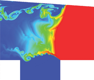
Figure 4 shows the detonation propagation in the supersonic model combustor after the hot jet is shut down. It is observed in figure 4(a) that a small unburned jet is generated behind the detonation front due to the interaction of the Mach stem with the Prandtl–Meyer expansion fan. A detached shear layer is generated near the unburned jet due to the triple point collision on the expanding wall. At this moment, only one triple point is observed on the detonation front.

Figure 4. Temperature contours showing detonation evolution after the shutdown of the hot jet: (a)  $t = 345\;\mathrm{\mu }\textrm{s}$, and (b)
  $t = 405\;\mathrm{\mu }\textrm{s}$.
Although the hot jet is shut down, the detonation still continues its forward propagation for a while until it reaches the farthest position at approximately X = 58.6 mm, where the hot jet effect is fully dissipated, as shown in figure 4(b). In the expanding wall region, the flow behind the detonation front is subsonic, and thus the detonation experiences a lateral mass divergence (Radulescu & Borzou Reference Radulescu and Borzou2018) brought by the area expansion. During this period, the detonation wave begins to attenuate gradually, which leads to a weaker detonation as well as the appearance of multiple secondary triple points as observed on the detonation front in figure 4(b). Maxwell et al. (Reference Maxwell, Bhattacharjee, Lau-Chapdelaine, Falle, Sharpe and Radulescu2017) have reported that the triple point is a location of high temperature and pressure due to shock compression from multiple waves as well as a source of enhanced turbulent mixing. These triple points can give rise to slip lines further developing into shear layers that are susceptible to the Kelvin–Helmholtz (KH) instability (Massa, Austin & Jackson Reference Massa, Austin and Jackson2007), hence acting to enhance the turbulent mixing between the unburned pockets and burned gases (Gamezo, Ogawa & Oran Reference Gamezo, Ogawa and Oran2007; Oran & Gamezo Reference Oran and Gamezo2007). It is seen in figure 4(b) that, near the expanding wall, large-scale vortices are produced due to the interaction between the unburned jet and highly unstable shear layers emitted from secondary triple points. Some partly unburned pockets are even observed away from the detonation front after separating from the main unburned jet. These large-scale vortices can enhance the turbulent mixing between the unburned pockets and burned product, facilitating the consumption of the unburned pockets.
Globally, the Reynolds number is estimated using the average density ( $\rho$), speed of sound (
 $a$) and velocity (
 $v$) at the top and bottom of the shear layer behind the triple point. It is noted that, in this definition of the Reynolds number, the time (
 $t$) when the shear layer begins to become unstable is used. Here, the Reynolds numbers in figure 4(a,b) are Re = 5 × 10⁴ and Re = 1 × 10⁵, respectively. Dimotakis (Reference Dimotakis2005) has reported that Re = 105 is an order of magnitude larger than the typical value for the onset of turbulence in mixing layers. The turbulence in detonations arises primarily from the jetting action of the slip lines and the KH instability along the shear layers (Radulescu et al. Reference Radulescu, Sharpe, Lee, Kiyanda, Higgins and Hanson2005). Therefore, after the shutdown of the hot jet, the flow field around the unburned jet associated with the highly unstable shear layers behind the detonation front is in the turbulent regime after the detonation wave reaches the farthest position. This can further accelerate the consumption of the unburned jet by turbulent mixing.
As shown in figure 5, the successive four frames properly illustrate the oscillatory quasi-steady detonation propagation, where the detonation front oscillates almost at the same position of approximately X = 56.5 mm. Near the expanding wall the structure of a shock-induced combustion wave is generated, as shown in figure 5(a). Behind the shock-induced combustion there are a series of large-scale vortices, and two main triple points are observed on the detonation front, propagating towards the lower wall. Therefore, the overall stabilization configuration is a combination of the detonation wave in the lower part and shock-induced combustion in the upper part. After further propagation, the triple points begin to move upwards upon the collision with the lower wall. A small unburned jet is clearly observed at this moment as shown in figure 5(b), which is larger than that in figure 5(a). The large-scale vortex near the expanding wall is further dissipated due to the diffusion and mixing effects compared with that in figure 5(a) and further vanishes almost entirely in figure 5(c). Owing to the triple point collisions, detached shear layers are generated and subsequently interact with the large-scale vortices. With its extension of the newly generated unburned jet, vortices are produced along the unburned jet due to the KH instability, as seen in figure 5(d). After the interaction with the highly unstable shear layers emitted from the secondary triple points, these small-scale vortices gradually become large, thus accelerating the heat release through consumption of the unburned jet due to the enhanced diffusion and mixing effects. The results shown in figure 5 illustrate a fully periodic process of quasi-steady detonation propagation.

Figure 5. Quasi-steady detonation propagation using product mass fraction contours: (a)  $t = 730\;\mathrm{\mu }\textrm{s}$, (b)
  $t = 740\;\mathrm{\mu }\textrm{s}$, (c)
  $t = 750\;\mathrm{\mu }\textrm{s}$ and (d)
  $t = 760\;\mathrm{\mu }\textrm{s}$.
3.2. Stabilization mechanism
In supersonic flows through straight channels, the detonation wave begins its attenuation process associated with continuous backward propagation when the influence of the hot jet is dissipated (Cai et al. Reference Cai, Deiterding, Liang, Sun and Mahmoudi2018b). However, as illustrated in figure 5, the detonation wave realizes quasi-steady detonation propagation in the supersonic model combustor. Therefore, it seems reasonable to assume that the supersonic model combustor can contribute to the realization of detonation stabilization. In order to differentiate the effect of the expanding wall from that of the cavity in the supersonic model combustor on the quasi-steady propagation of the detonation wave, two comparison cases are studied: model 1 considers a straight channel with a cavity, and model 2 employs an expanding channel without a cavity, while the other conditions remain the same.
Figure 6 shows the detonation structures for both models after the shutdown of the hot jet at  $t = 310\;\mathrm{\mu }\textrm{s}$. For model 1, two triple points are clearly observed in both figure 6(a,b). After the triple point reflections, detached shear layers are generated in figure 6(b). Compared with figure 5, no unburned jet is produced. Therefore, the flow field seems to be more laminar due to the absence of highly unstable shear layers. For model 2 in figure 6(c), an unburned jet associated with the shear layer is generated because of the Prandtl–Meyer expansion.

Figure 6. Numerical species schlieren showing detonation structures: model 1, (a)  $t = 370\;\mathrm{\mu }\textrm{s}$ and (b)
  $t = 390\;\mathrm{\mu }\textrm{s}$; and model 2, (c)
  $t = 370\;\mathrm{\mu }\textrm{s}$ and (d)
  $t = 390\;\mathrm{\mu }\textrm{s}$.
As a result of the Mach reflection configuration with respect to the plane of reflection, the slip line emanating from the primary triple point is redirected forwards, thus forming a jet tangential to the expanding wall (Shi et al. Reference Shi, Zhu, Yang and Luo2019). This jet shoots forwards along the wall towards the detonation front and gradually rolls up to form a vortex, resulting in the formation of the detonation bifurcation. With further evolution, a slight triple point reflection is formed, and the shear layer along the unburned jet is further extended and becomes highly unstable, as shown in figure 6(d). Compared with that in figure 5, the main difference is that fewer triple points are generated together with relatively weaker strength of the detonation front using the pressure ratio (approximately 5 % lower).
Figure 7 shows the comparison among the supersonic model combustor, model 1 and model 2. In figure 7(a), the trajectories of the detonation fronts are illustrated. It is seen that, for the model combustor, after reaching the farthest position at about  $t = 400\;\mathrm{\mu }\textrm{s}$, the detonation undergoes a slight backward propagation together with limited attenuation. Then, the trajectory curve globally begins to exhibit a plateau associated with periodic oscillations with an approximate period of
  $\Delta T = 30\;\mathrm{\mu }\textrm{s}$. This further verifies that a fluctuating quasi-steady propagation of detonation is eventually realized in the model combustor. For model 1, after the shutdown of the hot jet, the trajectory exhibits periodic oscillations, but presents an overall constant slope, suggesting the eventual overdriven state of detonation. Note that, if the straight channel is long enough, eventually, the detonation wave should also relax back to the CJ state and stabilize at a farther location. The relative velocity of the forward propagation, represented by the constant slope, is calculated as
  $\Delta v = 161.7\;\textrm{m}\;{\textrm{s}^{ - 1}}$ together with the corresponding overdrive degree of
  $f = 1.21$ (
 $f = {[({V_{CJ}} + \Delta v)/{V_{CJ}}]^2}$). The oscillation period is evaluated as
  $\Delta {T_{model\;1}} = 30.4\;\mathrm{\mu }\textrm{s}$, which is nearly the same as in the supersonic model combustor. This also indicates that the expanding wall does not have a significant influence on detonation oscillations. The trajectory in model 2 illustrates a different trend compared to that in model 1. After the shutdown of the hot jet, although the slope of the trajectory curve initially maintains a positive value, it turns negative at
  $t = 340\;\mathrm{\mu }\textrm{s}$ after going through a short period of attenuation. This implies that the forward propagation of the detonation changes quickly to a backward propagation under this condition.

Figure 7. (a) The trajectories of the detonation fronts and (b) pressure oscillations at the same position in the main flow: model 1, straight channel with a cavity; and model 2, expanding channel without a cavity.
It has been demonstrated (Cai et al. Reference Cai, Deiterding, Liang, Lin and Sun2018c) that in supersonic flows the acoustic wave produced by the subsonic combustion in the cavity can accelerate detonation propagation after crossing through a subsonic channel in the vicinity of the cavity edge, which can result in the generation of an overdriven detonation. This is also true in the supersonic model combustor, as demonstrated in figure 7(a). In the expanding channel, due to the lateral mass divergence resulting from the expanding wall, and the periodic formation and rapid consumption of the unburned jet resulting from the Prandtl–Meyer expansion fan, the detonation wave can be maintained almost in the same position.
Figure 7(b) illustrates pressure oscillations in the main flow, which are calculated at the same position. For the model combustor and model 1, pressures are highly oscillating during the initial period up to 300 μs. Nevertheless, the amplitude of pressure oscillation in the model combustor is significantly lower than that in model 1. The peak pressure in the model combustor is approximately 60 % of that in model 1, mainly due to the Prandtl–Meyer expansion fan. Because of the detonation stabilization in the model combustor, the pressure oscillation can maintain almost the same amplitude. However, for model 1, due to the forward propagation of the overdriven detonation, the pressure is decreased quickly at the beginning and gradually reaches a relatively periodic oscillation. For the model combustor and model 2, the pressure gradually begins to oscillate significantly during the backward detonation propagation, although no obvious pressure oscillation is observed in model 2 owing to the absence of the cavity.
It is indicated that the cavity in the supersonic flow could enhance pressure oscillations, which further facilitate the forward propagation of the detonation. On the other hand, the Prandtl–Meyer expansion fan resulting from the expanding wall can suppress pressure oscillations leading to detonation attenuation and failure. Therefore, in the supersonic model combustor consisting of the cavity and the expanding wall, the quasi-steady propagation of detonation can be properly realized as a result of two opposing effects.
3.3. Effects of the incoming velocity
Understanding the characteristics of detonation stabilization under the condition of different incoming velocities during accelerating or decelerating is important for detonation physics and practical applications. Based on the case in § 3.1, two cases with different characteristic incoming velocities are considered here, as shown in figure 8. Run 1 uses an inflow velocity lower than the CJ velocity (i.e. 0.95 VCJ) and run 2 adopts an inflow speed higher than the CJ velocity (i.e. 1.05 VCJ).

Figure 8. Contours of reactant mass fraction illustrating detonation propagation: run 1, (a)  $t = 325\;\mathrm{\mu }\textrm{s}$ and (b)
  $t = 335\;\mathrm{\mu }\textrm{s}$; and run 2, (c)
  $t = 615\;\mathrm{\mu}\mathrm{s}$ and (d)
  $t = 755\;\mathrm{\mu }\textrm{s}$.
For run 1, figure 8(a,b) shows that the overall structure continues its forward propagation after the shutdown of the hot jet. As seen in figure 8(a), an unburned jet has just been generated and the triple point is propagating downwards. After some time, however, as seen in figure 8(b), the unburned jet extends significantly and the triple point turns to upward propagation upon collision with the lower wall. Only one triple point (no secondary triple points) is observed on the detonation front and no obvious vortices are generated along the unburned jet.
This results in the absence of slip lines emitted from the triple points, which is quite different from that of the quasi-steady propagation of detonation discussed in the previous section. Without interactions of slip lines with the unburned jet, the diffusion and mixing effects on the unburned jet are suppressed, hence slowing down the consumption rate of the unburned jet and eventually leading to its obvious extension (Mazaheri, Mahmoudi & Radulescu Reference Mazaheri, Mahmoudi and Radulescu2012; Mahmoudi et al. Reference Mahmoudi, Karimi, Deiterding and Emami2014). This indicates that, when the incoming velocity is lower than the CJ value, supplementary methods should be utilized for realizing quasi-steady detonation propagation, which needs further investigation in future work.
For run 2, the detonation wave quickly turns to backward propagation after the shutdown of the hot jet. Rather than stabilization during the backward propagation, the detonation wave continues the backward propagation until reaching the cavity. The configuration consists of a detonation wave in the central flow accompanied by two unburned jets. Figure 8(c) illustrates the detonation wave interactions both with the cavity and with the expanding wall. When the detonation wave passes over the cavity, an oblique shock wave associated with an unburned jet is generated within the detonation front. The oblique shock wave is separated from the reaction front, indicating the formation of oblique shock-induced combustion. This is a typical structure of detonation bifurcation resulting from the detonation wave interaction with the cavity. In addition to pressure oscillations, the cavity permits a shear layer to be anchored at the leading edge, which introduces a large reacting surface for the unburned jet. It has been demonstrated that the diffusion and mixing effect resulting from the physical viscosity can facilitate the consumption of unburned pockets behind the detonation front, thus accelerating the heat release rate (Radulescu et al. Reference Radulescu, Sharpe, Law and Lee2007). Owing to the diffusion and mixing effects through the large reacting surface with neighboring burned gases, the generated unburned jet can be consumed effectively via which the chemical heat can be released rapidly. At this position, detonation bifurcation is developed underneath the expanding wall due to the generation of the wall jet, resulting in the generation of another unburned jet, as shown in figure 8(d). This structure mainly consists of one detonation front in the mainstream and two oblique shock-induced combustion waves associated with two unburned jets accompanying the detonation front.
Owing to adequate heat release resulting from the rapid consumption of the two unburned jets, which contributes significantly to the sustainment of detonation, the detonation begins its forward propagation once again, leading to the new generation of an overdriven detonation, as indicated in figure 9. However, the overdriven detonation begins to undergo an attenuation after it arrives at approximately X = 44 mm. When the overdriven detonation propagates forwards together with the gradual separation from the cavity, the unburned jet resulting from the detonation wave interaction with the cavity gradually decreases its size and eventually vanishes. This further reduces the heat release from the consumption of the unburned jet and finally results in the detonation attenuation. Subsequently, the detonation wave repeats the backward propagation and again the detonation bifurcation. This suggests that in the supersonic model combustor an oscillating periodic process is generated, including four stages of forward propagation, detonation attenuation, backward propagation and detonation bifurcation. In the four stages, the detonation attenuation leads to backward propagation while the forward propagation results from detonation bifurcation, indicating the formation of detonation stabilization in the supersonic model combustor.

Figure 9. The trajectory of the detonation front for run 2.
4. Summary and conclusions
In the present work, stabilization of a hydrogen/oxygen detonation in a supersonic model combustor is investigated by solving the reactive compressible Navier–Stokes equations and a one-step two-species reaction model using a hybrid sixth-order WENO-CD scheme within an SAMR framework.
A regularly fluctuating quasi-steady propagation of detonation can be realized in the supersonic model combustor when the detonation has propagated backwards after the shutdown of the hot jet. The overall configuration is in fact a detonation bifurcation consisting of a normal detonation wave and a shock-induced combustion front.
In this context, the realization of the quasi-steady propagation of detonation is due to the combined effects: (i) pressure oscillations generated in the cavity, which facilitate the detonation propagation; and (ii) lateral mass divergence brought by the expanding wall, which can lead to detonation attenuation, and an unburned jet associated with large-scale vortices resulting from a Prandtl–Meyer expansion fan, which can contribute to the stabilization.
When the incoming velocity is lower than the CJ value, an overdriven detonation is generated; however, when the incoming velocity is larger than the CJ value, because of the formation of a periodic process of forward propagation, detonation attenuation, backward propagation and detonation bifurcation quasi-steady propagation of detonation can be realized effectively in the supersonic model combustor.
Acknowledgements
This work is supported by the National Natural Science Foundation of China (no. 11702323), and the National Postdoctoral Program for Innovative Talent (no. BX20180372).
Declaration of interests
The authors report no conflict of interest.


