1 Introduction
Locomotion of motile microorganisms near a wall/interface is ubiquitous in nature, due to which there has been a large body of literature to explain the available experimental observations (see the sections on swimming near surfaces in Lauga & Powers (Reference Lauga and Powers2009) and Elgeti, Winkler & Gompper (Reference Elgeti, Winkler and Gompper2015)). The presence of a non-deforming wall/interface can influence the dynamics of a swimming microorganism near it in a few ways. First, it can modify the speed of a microorganism. For instance, a Taylor swimming sheet, with a fixed waveform, is found to swim faster near a wall than in the bulk (Reynolds Reference Reynolds1965; Katz Reference Katz1974). Second, it can modify the trajectory of a microorganism. For instance, microorganisms such as Escherichia coli (E. coli), which swim in straight lines in the bulk, are found to swim in circles near a plane interface (Lauga et al. Reference Lauga, DiLuzio, Whitesides and Stone2006; Di Leonardo et al. Reference Di Leonardo, Dell’Arciprete, Angelani and Iebba2011). The direction of rotation (clockwise or anticlockwise) depends on any slip on the plane wall, the viscosity ratio of the plane interface and the advection of the impurities (if any) on the plane interface (Lopez & Lauga Reference Lopez and Lauga2014). Third, the wall/interface causes reorientation and attraction of microorganisms towards it. For instance, pusher swimmers (e.g. E. coli) reorient parallel to a plane wall and move towards the wall. On the other hand, puller swimmers (e.g. Chlamydomonas) reorient normal to a plane wall and collide with it. One can explain the reorientation and attraction to the wall using either (a) the hydrodynamic interactions between the swimmer and the wall (Berke et al. Reference Berke, Turner, Berg and Lauga2008; Spagnolie & Lauga Reference Spagnolie and Lauga2012; Lopez & Lauga Reference Lopez and Lauga2014) or (b) the self-propulsion and Brownian motion of the swimmer (Elgeti & Gompper Reference Elgeti and Gompper2009; Li & Tang Reference Li and Tang2009).
Among the works on the motion of a motile microorganism near an interface, some have focused on the influence of (a) interface deformation (Lee et al.
Reference Lee, Bush, Hosoi and Lauga2008; Trouilloud et al.
Reference Trouilloud, Yu, Hosoi and Lauga2008; Crowdy et al.
Reference Crowdy, Lee, Samson, Lauga and Hosoi2011; Shaik & Ardekani Reference Shaik and Ardekani2017a
), (b) non-Newtonian fluid behaviour (Li, Karimi & Ardekani Reference Li, Karimi and Ardekani2014; Yazdi, Ardekani & Borhan Reference Yazdi, Ardekani and Borhan2015) and (c) the surfactant advection (Lopez & Lauga Reference Lopez and Lauga2014; Shaik & Ardekani Reference Shaik and Ardekani2017b
; Desai, Shaik & Ardekani Reference Desai, Shaik and Ardekani2018) on the dynamics of the swimmer. It was found that the attraction and reorientation behaviour of a pusher swimmer near a plane surfactant-laden interface is similar to that near a plane wall, but the surfactant redistribution can cause the microorganism to circle the interface in an opposite direction compared with its circling near a clean interface (Lopez & Lauga Reference Lopez and Lauga2014). Later, it was observed that the swimming microorganism gets trapped onto a spherical surfactant-laden drop similarly to its trapping onto a rigid sphere, but the trapping due to a surfactant-laden drop is stronger than that due to a rigid sphere (Shaik & Ardekani Reference Shaik and Ardekani2017b
; Desai et al.
Reference Desai, Shaik and Ardekani2018). These works on the locomotion of swimming microorganisms near a plane/spherical surfactant-laden interface modelled the surfactant as incompressible (Sickert & Rondelez Reference Sickert and Rondelez2003; Fischer Reference Fischer2004; Sickert, Rondelez & Stone Reference Sickert, Rondelez and Stone2007; Samaniuk & Vermant Reference Samaniuk and Vermant2014) with zero surface diffusivity (the surface Péclet number,
![]() $Pe_{s}$
, the ratio of the surface advection to the surface diffusion of the surfactant, tends to infinity) accounting for the interfacial viscosity. We analyse the locomotion of swimming microorganisms near a surfactant-covered interface in the other limit of surface Péclet number, i.e. low surface Péclet number at which the surface diffusion of the surfactant dominates its surface advection.
$Pe_{s}$
, the ratio of the surface advection to the surface diffusion of the surfactant, tends to infinity) accounting for the interfacial viscosity. We analyse the locomotion of swimming microorganisms near a surfactant-covered interface in the other limit of surface Péclet number, i.e. low surface Péclet number at which the surface diffusion of the surfactant dominates its surface advection.
An artificial/biological microswimmer must break the time-reversal symmetry (getting around the constraints of the scallop theorem) in order to swim at low Reynolds number (Purcell Reference Purcell1977). It can escape from the constraints of the scallop theorem in one of the following ways (Lauga Reference Lauga2011): (a) by passing waves along its flagella or its whole body, (b) by rotating the flexible flagella, (c) through the finite inertia of the fluid or the swimmer, (d) through the hydrodynamic interactions with a flexible membrane/interface, (e) due to the non-Newtonian behaviour of the suspending fluid. In other words, the scallop theorem is not valid if there are any time-derivative terms or nonlinear terms in the governing equations and the boundary conditions.
Particles and drops, on the other hand, exhibit several interesting phenomena due to such nonlinearities (Leal Reference Leal1980). For instance, due to inertia, non-Newtonian suspending fluid or the deformation of the particle/drop, (a) a spherical particle placed in a unidirectional shear/Poiseuille flow field migrates in a transverse direction to a fixed position that is independent of its initial position, (b) a sedimenting axisymmetric particle in an unbounded quiescent fluid achieves an orientation that is independent of its initial orientation and (c) a freely rotating axisymmetric particle placed in a simple shear flow achieves a final orbit that is independent of its initial orientation. Recent works (Hanna & Vlahovska Reference Hanna and Vlahovska2010; Schwalbe et al. Reference Schwalbe, Phelan, Vlahovska and Hudson2011; Pak, Feng & Stone Reference Pak, Feng and Stone2014) have shown that transverse migration of the drop, in an unbounded Poiseuille flow, to a fixed position is also possible due to the nonlinearities in the advection of the surfactant on the surface of the drop.
In summary, nonlinearities in the flow can enable a particle to achieve a fixed position/orientation independent of its initial configuration, while they can also make a swimming microorganism display a net motion. Since such breakdown of kinematic reversibility was recently shown in the context of a surfactant-laden drop achieving a fixed position (nonlinearities due to the surfactant redistribution), we would like to know whether a time-reversible swimmer near a surfactant-laden interface can have a net motion.
In this work, we study the locomotion of a spherical microswimmer inside a surfactant-laden drop for axisymmetric configurations by taking a perturbation in
![]() $Pe_{s}$
. Similar work, but on the locomotion inside a clean drop, was carried out by Reigh et al. (Reference Reigh, Zhu, Gallaire and Lauga2017). One of the applications of our work is to understand the physics underlying recent experiments on using artificial bacterial flagella (ABF) to transport a surfactant-laden drop (Ding et al.
Reference Ding, Qiu, Casadevall i Solvas, Chiu, Nelson and Demello2016). According to Ding et al. (Reference Ding, Qiu, Casadevall i Solvas, Chiu, Nelson and Demello2016), ABF placed inside a stationary drop (since the size of the drop is larger than the microfluidic channel in which it resides, the drop is stationary) can transport the contents within the drop through the application of magnetic field. As mentioned by Reigh et al. (Reference Reigh, Zhu, Gallaire and Lauga2017), if the radius of the drop is smaller than the characteristic size of the microfluidic channel, and the affinity of the drop to the wall is negligible, an ABF placed inside a drop can propel the drop, similarly to the system studied in this paper.
$Pe_{s}$
. Similar work, but on the locomotion inside a clean drop, was carried out by Reigh et al. (Reference Reigh, Zhu, Gallaire and Lauga2017). One of the applications of our work is to understand the physics underlying recent experiments on using artificial bacterial flagella (ABF) to transport a surfactant-laden drop (Ding et al.
Reference Ding, Qiu, Casadevall i Solvas, Chiu, Nelson and Demello2016). According to Ding et al. (Reference Ding, Qiu, Casadevall i Solvas, Chiu, Nelson and Demello2016), ABF placed inside a stationary drop (since the size of the drop is larger than the microfluidic channel in which it resides, the drop is stationary) can transport the contents within the drop through the application of magnetic field. As mentioned by Reigh et al. (Reference Reigh, Zhu, Gallaire and Lauga2017), if the radius of the drop is smaller than the characteristic size of the microfluidic channel, and the affinity of the drop to the wall is negligible, an ABF placed inside a drop can propel the drop, similarly to the system studied in this paper.
The governing equations (Stokes) and boundary conditions concerning the locomotion of a spherical swimmer inside a surfactant-covered drop are provided in § 2. For the concentric configuration, the procedure for solving the Stokes equations using Lamb’s general solution is given in § 3.1. For the eccentric configurations, the methodology for solving the dynamic equation for the stream function in the bipolar coordinates is given in § 3.2. We present the results for the concentric and eccentric configurations in § 4.1 and § 4.2, providing reasons for the results in § 4.2 using the drag and thrust analogy in § 4.3. We then discuss how a time-reversible swimmer inside a surfactant-laden drop escapes from the constraints of the scallop theorem in § 4.4, and provide the main conclusions in § 5. The technical details of several derivations, expressions for the flow field, conversion between different coordinate systems and the validation of bipolar coordinate system results are given in the appendices.
2 Mathematical model
We consider the motion of a swimming microorganism inside a surfactant-laden drop, with the orientation of the swimmer along the line joining the centres of the swimmer and the drop. Assuming the capillary number (ratio of the bulk viscous stress to the capillary stresses) to be
![]() $Ca\ll 1$
, we neglect the deformation of the drop and regard the shape of the drop and the swimmer as a sphere. The swimmer propels and, through the hydrodynamic interactions, it causes the drop to move. We hereby formulate this problem in the frame of reference of the drop. The flow fields inside (phase 1) and outside (phase 2) the drop are governed by the creeping motion equations and an incompressibility condition since the inertia of the fluid can be neglected. Using the characteristic scales for the length, velocity and stresses as the radius of the drop
$Ca\ll 1$
, we neglect the deformation of the drop and regard the shape of the drop and the swimmer as a sphere. The swimmer propels and, through the hydrodynamic interactions, it causes the drop to move. We hereby formulate this problem in the frame of reference of the drop. The flow fields inside (phase 1) and outside (phase 2) the drop are governed by the creeping motion equations and an incompressibility condition since the inertia of the fluid can be neglected. Using the characteristic scales for the length, velocity and stresses as the radius of the drop
![]() $a$
, the characteristic velocity of the swimmer in an unbounded fluid
$a$
, the characteristic velocity of the swimmer in an unbounded fluid
![]() $U_{sq}$
and
$U_{sq}$
and
![]() $\unicode[STIX]{x1D707}^{(k)}U_{sq}/a$
, where
$\unicode[STIX]{x1D707}^{(k)}U_{sq}/a$
, where
![]() $\unicode[STIX]{x1D707}^{(k)}$
is the dynamic viscosity of the
$\unicode[STIX]{x1D707}^{(k)}$
is the dynamic viscosity of the
![]() $k$
th phase, the dimensionless governing equations are given by
$k$
th phase, the dimensionless governing equations are given by
Here,
![]() $p^{(k)}$
and
$p^{(k)}$
and
![]() $\boldsymbol{v}^{(k)}$
denote the pressure and the velocity of the
$\boldsymbol{v}^{(k)}$
denote the pressure and the velocity of the
![]() $k$
th phase. The fluid inside the drop should satisfy the no-slip and no-penetration boundary conditions on the surface of the swimmer.
$k$
th phase. The fluid inside the drop should satisfy the no-slip and no-penetration boundary conditions on the surface of the swimmer.
where
![]() $\boldsymbol{U}_{S}=U_{S}\boldsymbol{i}_{z}$
and
$\boldsymbol{U}_{S}=U_{S}\boldsymbol{i}_{z}$
and
![]() $\boldsymbol{U}_{D}=U_{D}\boldsymbol{i}_{z}$
are the velocities of the swimmer and the drop respectively,
$\boldsymbol{U}_{D}=U_{D}\boldsymbol{i}_{z}$
are the velocities of the swimmer and the drop respectively,
![]() $\boldsymbol{u}^{s}$
denotes the slip velocity on the surface of the swimmer and
$\boldsymbol{u}^{s}$
denotes the slip velocity on the surface of the swimmer and
![]() $\boldsymbol{i}_{z}$
is the unit vector along the
$\boldsymbol{i}_{z}$
is the unit vector along the
![]() $z$
-axis. The swimmer and the drop are assumed to be neutrally buoyant. Since the external force acting on the drop and the swimmer is zero, the hydrodynamic forces acting on each of them (
$z$
-axis. The swimmer and the drop are assumed to be neutrally buoyant. Since the external force acting on the drop and the swimmer is zero, the hydrodynamic forces acting on each of them (
![]() $\boldsymbol{F}_{S}$
, the hydrodynamic force on the swimmer;
$\boldsymbol{F}_{S}$
, the hydrodynamic force on the swimmer;
![]() $\boldsymbol{F}_{D}$
, the hydrodynamic force on the drop) should be zero,
$\boldsymbol{F}_{D}$
, the hydrodynamic force on the drop) should be zero,
where
![]() $\boldsymbol{n}$
is the normal vector on the surface of the swimmer (drop) pointing into the suspending fluid,
$\boldsymbol{n}$
is the normal vector on the surface of the swimmer (drop) pointing into the suspending fluid,
![]() $\unicode[STIX]{x1D64F}^{(k)}$
is the stress tensor for the
$\unicode[STIX]{x1D64F}^{(k)}$
is the stress tensor for the
![]() $k$
th phase,
$k$
th phase,
![]() $\text{d}S$
is an infinitesimal surface area on the surface of the swimmer (drop) and the integration is performed on the surface of the swimmer (drop). Using the Newtonian constitutive equation, the stress tensor for the
$\text{d}S$
is an infinitesimal surface area on the surface of the swimmer (drop) and the integration is performed on the surface of the swimmer (drop). Using the Newtonian constitutive equation, the stress tensor for the
![]() $k$
th phase can be expressed as
$k$
th phase can be expressed as
![]() $\unicode[STIX]{x1D64F}^{(k)}=-p^{(k)}\unicode[STIX]{x1D644}+[\unicode[STIX]{x1D735}\boldsymbol{v}^{(k)}+(\unicode[STIX]{x1D735}\boldsymbol{v}^{(k)})^{\text{T}}]$
, where
$\unicode[STIX]{x1D64F}^{(k)}=-p^{(k)}\unicode[STIX]{x1D644}+[\unicode[STIX]{x1D735}\boldsymbol{v}^{(k)}+(\unicode[STIX]{x1D735}\boldsymbol{v}^{(k)})^{\text{T}}]$
, where
![]() $\unicode[STIX]{x1D644}$
is the identity tensor and the superscript
$\unicode[STIX]{x1D644}$
is the identity tensor and the superscript
![]() $\text{T}$
stands for the transpose. In the frame of reference of the drop, the flow field far away from the drop should approach the negative of the drop velocity.
$\text{T}$
stands for the transpose. In the frame of reference of the drop, the flow field far away from the drop should approach the negative of the drop velocity.
At the surface of the drop, the flow field in both of the phases should satisfy the kinematic, dynamic and stress balance conditions. Since the drop is non-deforming and stationary, the kinematic and dynamic conditions are given as follows.
Similarly, the dimensional tangential stress balance condition is given as follows.
where
![]() $\unicode[STIX]{x1D6FE}$
is the interfacial tension and the surface gradient operator is
$\unicode[STIX]{x1D6FE}$
is the interfacial tension and the surface gradient operator is
![]() $\unicode[STIX]{x1D735}_{s}=\unicode[STIX]{x1D71F}\boldsymbol{\cdot }\unicode[STIX]{x1D735}$
. In general, the interfacial tension depends on the surfactant concentration
$\unicode[STIX]{x1D735}_{s}=\unicode[STIX]{x1D71F}\boldsymbol{\cdot }\unicode[STIX]{x1D735}$
. In general, the interfacial tension depends on the surfactant concentration
![]() $(\unicode[STIX]{x1D6E4})$
. Assuming that the local surfactant concentration
$(\unicode[STIX]{x1D6E4})$
. Assuming that the local surfactant concentration
![]() $(\unicode[STIX]{x1D6E4})$
is much smaller than the maximum possible surfactant concentration on the interface
$(\unicode[STIX]{x1D6E4})$
is much smaller than the maximum possible surfactant concentration on the interface
![]() $(\unicode[STIX]{x1D6E4}_{\infty })$
, i.e.
$(\unicode[STIX]{x1D6E4}_{\infty })$
, i.e.
![]() $\unicode[STIX]{x1D6E4}/\unicode[STIX]{x1D6E4}_{\infty }\ll 1$
, we use a linear constitutive relationship between the interfacial tension and the surfactant concentration, which, in its dimensional form, is given as
$\unicode[STIX]{x1D6E4}/\unicode[STIX]{x1D6E4}_{\infty }\ll 1$
, we use a linear constitutive relationship between the interfacial tension and the surfactant concentration, which, in its dimensional form, is given as
![]() $\unicode[STIX]{x1D6FE}=\unicode[STIX]{x1D6FE}_{s}-\unicode[STIX]{x1D6E4}RT$
. Here,
$\unicode[STIX]{x1D6FE}=\unicode[STIX]{x1D6FE}_{s}-\unicode[STIX]{x1D6E4}RT$
. Here,
![]() $\unicode[STIX]{x1D6FE}_{s}$
is the interfacial tension of the clean interface,
$\unicode[STIX]{x1D6FE}_{s}$
is the interfacial tension of the clean interface,
![]() $R$
is the ideal gas constant and
$R$
is the ideal gas constant and
![]() $T$
is the absolute temperature. Enforcing this relation in the stress balance equation and non-dimensionalizing it using
$T$
is the absolute temperature. Enforcing this relation in the stress balance equation and non-dimensionalizing it using
![]() $\unicode[STIX]{x1D6E4}_{ref}=\unicode[STIX]{x1D6E4}_{eq}$
(equilibrium concentration of surfactant), we derive the dimensionless tangential stress balance condition as follows.
$\unicode[STIX]{x1D6E4}_{ref}=\unicode[STIX]{x1D6E4}_{eq}$
(equilibrium concentration of surfactant), we derive the dimensionless tangential stress balance condition as follows.
Here,
![]() $\unicode[STIX]{x1D706}=\unicode[STIX]{x1D707}^{(1)}/\unicode[STIX]{x1D707}^{(2)}$
is the viscosity ratio and
$\unicode[STIX]{x1D706}=\unicode[STIX]{x1D707}^{(1)}/\unicode[STIX]{x1D707}^{(2)}$
is the viscosity ratio and
![]() $Ma=RT\unicode[STIX]{x1D6E4}_{eq}/(\unicode[STIX]{x1D707}^{(2)}U_{sq})$
is the Marangoni number, which is the ratio of the Marangoni forces to the viscous forces.
$Ma=RT\unicode[STIX]{x1D6E4}_{eq}/(\unicode[STIX]{x1D707}^{(2)}U_{sq})$
is the Marangoni number, which is the ratio of the Marangoni forces to the viscous forces.
Finally, the surfactant transport equation (Stone Reference Stone1990; Leal Reference Leal2007) governs the distribution of surfactant on the drop surface. We simplify the surfactant transport equation in the limits of insoluble surfactant and quasi-steady-state conditions (Hanna & Vlahovska Reference Hanna and Vlahovska2010; Pak et al.
Reference Pak, Feng and Stone2014; Mandal, Ghosh & Chakraborty Reference Mandal, Ghosh and Chakraborty2016). In the insoluble limit, bulk surfactant does not influence the surfactant distribution on the interface. This limit is valid when
![]() $c_{\infty }a/(\unicode[STIX]{x1D6E4}_{eq}Pe^{(1)})\ll O(1)$
and
$c_{\infty }a/(\unicode[STIX]{x1D6E4}_{eq}Pe^{(1)})\ll O(1)$
and
![]() $c_{\infty }a/(\unicode[STIX]{x1D6E4}_{eq}Pe^{(2)})\ll O(1)$
or
$c_{\infty }a/(\unicode[STIX]{x1D6E4}_{eq}Pe^{(2)})\ll O(1)$
or
![]() $Bi=\unicode[STIX]{x1D6FC}^{(2)}a/U_{sq}\ll O(1)$
. Here,
$Bi=\unicode[STIX]{x1D6FC}^{(2)}a/U_{sq}\ll O(1)$
. Here,
![]() $c_{\infty }$
is the reference bulk concentration of the surfactant,
$c_{\infty }$
is the reference bulk concentration of the surfactant,
![]() $Pe^{(k)}$
is the Péclet number, defined as the ratio of the bulk advection of the surfactant to its bulk diffusion in the
$Pe^{(k)}$
is the Péclet number, defined as the ratio of the bulk advection of the surfactant to its bulk diffusion in the
![]() $k$
th fluid,
$k$
th fluid,
![]() $Bi$
is the Biot number, characterizing the strength of kinetic desorption relative to the interfacial convection, and
$Bi$
is the Biot number, characterizing the strength of kinetic desorption relative to the interfacial convection, and
![]() $\unicode[STIX]{x1D6FC}^{(2)}$
is the desorption rate constant. In these limits, the dimensionless surfactant transport equation is given as
$\unicode[STIX]{x1D6FC}^{(2)}$
is the desorption rate constant. In these limits, the dimensionless surfactant transport equation is given as
Here,
![]() $Pe_{s}=U_{sq}a/D_{s}$
is the surface or interface Péclet number,
$Pe_{s}=U_{sq}a/D_{s}$
is the surface or interface Péclet number,
![]() $D_{s}$
is the surface or interface diffusivity and
$D_{s}$
is the surface or interface diffusivity and
![]() $\boldsymbol{v}_{s}$
is the tangential velocity of the fluid on the surface of the drop, i.e.
$\boldsymbol{v}_{s}$
is the tangential velocity of the fluid on the surface of the drop, i.e.
![]() $\boldsymbol{v}_{s}=\unicode[STIX]{x1D71F}\boldsymbol{\cdot }\boldsymbol{v}^{(1)}|_{Drop}=\unicode[STIX]{x1D71F}\boldsymbol{\cdot }\boldsymbol{v}^{(2)}|_{Drop}$
.
$\boldsymbol{v}_{s}=\unicode[STIX]{x1D71F}\boldsymbol{\cdot }\boldsymbol{v}^{(1)}|_{Drop}=\unicode[STIX]{x1D71F}\boldsymbol{\cdot }\boldsymbol{v}^{(2)}|_{Drop}$
.
The problem governed by (2.1)–(2.9) is essentially nonlinear, so we need to make an assumption to analytically solve these equations. We assume that
![]() $Pe_{s}\ll 1$
and expand all of the variables as a regular perturbation in
$Pe_{s}\ll 1$
and expand all of the variables as a regular perturbation in
![]() $Pe_{s}$
,
$Pe_{s}$
,
By substituting this expansion in (2.1)–(2.9) and collecting terms at various orders of
![]() $Pe_{s}$
, we derive the governing equations and boundary conditions at several orders of
$Pe_{s}$
, we derive the governing equations and boundary conditions at several orders of
![]() $Pe_{s}$
which are summarized in the following subsection.
$Pe_{s}$
which are summarized in the following subsection.
2.1 Governing equations and boundary conditions at various orders of
 $Pe_{s}$
The flow field at each order of
![]() $Pe_{s}$
satisfies the creeping flow equations and an incompressibility condition,
$Pe_{s}$
satisfies the creeping flow equations and an incompressibility condition,
Assuming that the slip velocity
![]() $\boldsymbol{u}^{s}$
is
$\boldsymbol{u}^{s}$
is
![]() $O(1)$
, the flow field should satisfy the following boundary condition on the swimmer.
$O(1)$
, the flow field should satisfy the following boundary condition on the swimmer.
where
![]() $\unicode[STIX]{x1D6FF}_{j,0}$
is the Kronecker delta. The force-free conditions on the swimmer and the drop are given as
$\unicode[STIX]{x1D6FF}_{j,0}$
is the Kronecker delta. The force-free conditions on the swimmer and the drop are given as
Far away from the drop, the flow field should approach the negative of the drop velocity at various orders of
![]() $Pe_{s}$
.
$Pe_{s}$
.
On the surface of the drop, the kinematic, dynamic and the shear-stress balance conditions are given as follows.
The perturbed surfactant transport equations at different orders of
![]() $Pe_{s}$
are given as follows.
$Pe_{s}$
are given as follows.
Here,
![]() $\boldsymbol{v}_{j,s}$
is the tangential velocity of the fluid at
$\boldsymbol{v}_{j,s}$
is the tangential velocity of the fluid at
![]() $O(Pe_{s}^{j})$
evaluated on the surface of the drop, i.e.
$O(Pe_{s}^{j})$
evaluated on the surface of the drop, i.e.
![]() $\boldsymbol{v}_{j,s}=\unicode[STIX]{x1D71F}\boldsymbol{\cdot }\boldsymbol{v}_{j}^{(1)}|_{Drop}=\unicode[STIX]{x1D71F}\boldsymbol{\cdot }\boldsymbol{v}_{j}^{(2)}|_{Drop}$
.
$\boldsymbol{v}_{j,s}=\unicode[STIX]{x1D71F}\boldsymbol{\cdot }\boldsymbol{v}_{j}^{(1)}|_{Drop}=\unicode[STIX]{x1D71F}\boldsymbol{\cdot }\boldsymbol{v}_{j}^{(2)}|_{Drop}$
.
3 Solution methodology
In this section, we describe the techniques used to solve the aforementioned perturbed equations for axisymmetric configurations. For all non-zero values of eccentricities, we use the bipolar coordinate approach to solve for the stream function. For the concentric configuration, since the bipolar coordinate solution is singular, we use Lamb’s general solution to solve for the flow field. Solving for the concentric configuration is especially important, as the expressions for the flow field are simple and hence they can be used to describe the underlying physics.
When the perturbation is taken in
![]() $Pe_{s}$
(Pak et al.
Reference Pak, Feng and Stone2014), the key idea is to first find the surfactant concentration at
$Pe_{s}$
(Pak et al.
Reference Pak, Feng and Stone2014), the key idea is to first find the surfactant concentration at
![]() $O(Pe_{s}^{j})(\unicode[STIX]{x1D6E4}_{j})$
by solving the surfactant transport equation at the same order in
$O(Pe_{s}^{j})(\unicode[STIX]{x1D6E4}_{j})$
by solving the surfactant transport equation at the same order in
![]() $Pe_{s}$
. This equation can be solved to determine
$Pe_{s}$
. This equation can be solved to determine
![]() $\unicode[STIX]{x1D6E4}_{j}$
because it contains only the flow field and surfactant concentrations at lower orders of
$\unicode[STIX]{x1D6E4}_{j}$
because it contains only the flow field and surfactant concentrations at lower orders of
![]() $Pe_{s}$
, which are known quantities (see (2.19)–(2.21) for instance). Once
$Pe_{s}$
, which are known quantities (see (2.19)–(2.21) for instance). Once
![]() $\unicode[STIX]{x1D6E4}_{j}$
is found, one can use it to solve the Stokes equations at
$\unicode[STIX]{x1D6E4}_{j}$
is found, one can use it to solve the Stokes equations at
![]() $O(Pe_{s}^{j})$
so as to find the swimmer and drop velocities at
$O(Pe_{s}^{j})$
so as to find the swimmer and drop velocities at
![]() $O(Pe_{s}^{j})$
. Instead, one can avoid the process of solving for the
$O(Pe_{s}^{j})$
. Instead, one can avoid the process of solving for the
![]() $O(Pe_{s}^{j})$
flow field and use an integral theorem to directly find the
$O(Pe_{s}^{j})$
flow field and use an integral theorem to directly find the
![]() $O(Pe_{s}^{j})$
swimmer and drop velocities from the knowledge of the
$O(Pe_{s}^{j})$
swimmer and drop velocities from the knowledge of the
![]() $O(Pe_{s}^{j})$
surfactant concentration and the solution of two auxiliary problems. We direct the reader to appendix C for a detailed derivation of this integral theorem, (C 17)–(C 18), and a demonstration of the use of this integral theorem in calculating the swimmer and drop velocities. We, however, do not use this integral theorem and use the former approach of solving the Stokes equations at any order of
$O(Pe_{s}^{j})$
surfactant concentration and the solution of two auxiliary problems. We direct the reader to appendix C for a detailed derivation of this integral theorem, (C 17)–(C 18), and a demonstration of the use of this integral theorem in calculating the swimmer and drop velocities. We, however, do not use this integral theorem and use the former approach of solving the Stokes equations at any order of
![]() $Pe_{s}$
to find the swimmer and drop velocities at that order in
$Pe_{s}$
to find the swimmer and drop velocities at that order in
![]() $Pe_{s}$
.
$Pe_{s}$
.
We further note that the surfactant concentration at
![]() $O(1)$
is uniform
$O(1)$
is uniform
![]() $(\unicode[STIX]{x1D6E4}_{0}=1)$
, and hence the Marangoni term, proportional to the gradient of the surfactant concentration, is zero. Therefore, the flow field and the dynamics of the swimmer and the drop at
$(\unicode[STIX]{x1D6E4}_{0}=1)$
, and hence the Marangoni term, proportional to the gradient of the surfactant concentration, is zero. Therefore, the flow field and the dynamics of the swimmer and the drop at
![]() $O(1)$
are the same as those for the motion of a swimmer inside a clean drop. Reigh et al. (Reference Reigh, Zhu, Gallaire and Lauga2017) studied the motion of a swimmer inside a clean drop for concentric and eccentric configurations using Lamb’s general solution and the boundary element method respectively. The analytical results given in the present study recover their results in the limit of zero
$O(1)$
are the same as those for the motion of a swimmer inside a clean drop. Reigh et al. (Reference Reigh, Zhu, Gallaire and Lauga2017) studied the motion of a swimmer inside a clean drop for concentric and eccentric configurations using Lamb’s general solution and the boundary element method respectively. The analytical results given in the present study recover their results in the limit of zero
![]() $Pe_{s}$
or
$Pe_{s}$
or
![]() $Ma$
, corresponding to a clean drop.
$Ma$
, corresponding to a clean drop.
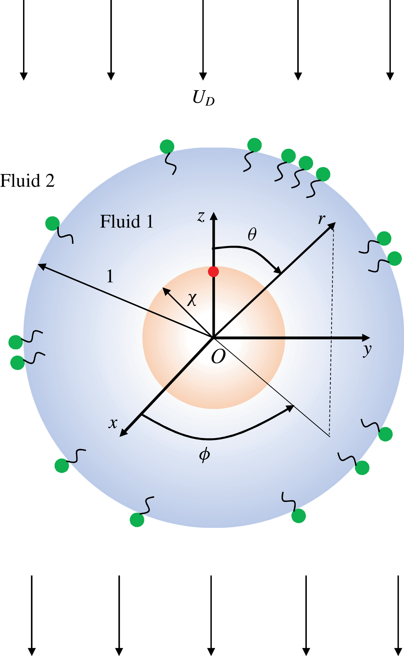
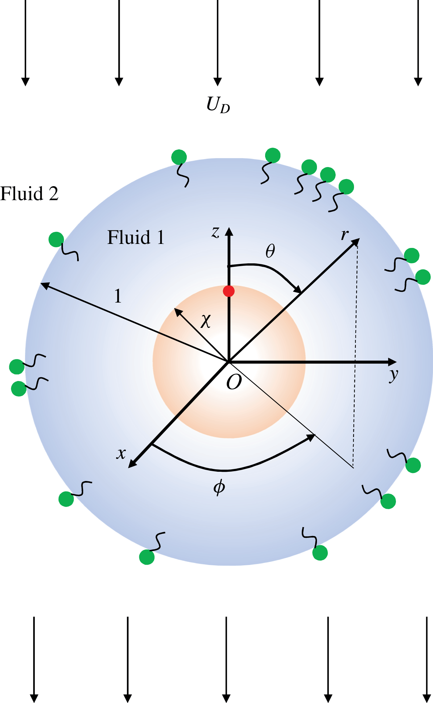
Figure 1. A schematic showing the geometric configuration of a swimmer located at the centre of the drop. A vector from the swimmer centre to the red circle gives the orientation of the swimmer. The origin
![]() $O$
is coincident with the centre of the swimmer and the drop. Here,
$O$
is coincident with the centre of the swimmer and the drop. Here,
![]() $(x,y,z)$
and
$(x,y,z)$
and
![]() $(r,\unicode[STIX]{x1D703},\unicode[STIX]{x1D719})$
denote the Cartesian and spherical coordinate variables respectively;
$(r,\unicode[STIX]{x1D703},\unicode[STIX]{x1D719})$
denote the Cartesian and spherical coordinate variables respectively;
![]() $r=1$
and
$r=1$
and
![]() $r=\unicode[STIX]{x1D712}$
denote the surfaces of the drop and the swimmer respectively. We denote the fluid inside and outside the drop as phases 1 and 2 respectively. In the drop frame of reference, the drop is stationary and it is placed in a uniform streaming flow,
$r=\unicode[STIX]{x1D712}$
denote the surfaces of the drop and the swimmer respectively. We denote the fluid inside and outside the drop as phases 1 and 2 respectively. In the drop frame of reference, the drop is stationary and it is placed in a uniform streaming flow,
![]() $-U_{D}\boldsymbol{i}_{z}$
.
$-U_{D}\boldsymbol{i}_{z}$
.
3.1 Concentric configuration
In this section, we provide the methodology to derive the surfactant concentration, flow field, swimmer and drop velocities at
![]() $O(Pe_{s}^{j})$
when the swimmer is located at the centre of the drop. We hereby place the origin at the centre of the drop and choose a spherical coordinate system (see figure 1 for the schematic), the most suitable coordinate system for the concentric configuration. In this coordinate system, the surface of the drop is located at
$O(Pe_{s}^{j})$
when the swimmer is located at the centre of the drop. We hereby place the origin at the centre of the drop and choose a spherical coordinate system (see figure 1 for the schematic), the most suitable coordinate system for the concentric configuration. In this coordinate system, the surface of the drop is located at
![]() $r=1$
, while the surface of the swimmer is at
$r=1$
, while the surface of the swimmer is at
![]() $r=\unicode[STIX]{x1D712}$
.
$r=\unicode[STIX]{x1D712}$
.
The most general form for the surfactant transport equation at
![]() $O(Pe_{s}^{j})$
, where
$O(Pe_{s}^{j})$
, where
![]() $j\geqslant 1$
, is given as
$j\geqslant 1$
, is given as
We expand the surfactant concentration
![]() $\unicode[STIX]{x1D6E4}_{j}$
in terms of the Legendre polynomials (Haber & Hetsroni Reference Haber and Hetsroni1972; Pak et al.
Reference Pak, Feng and Stone2014; Mandal et al.
Reference Mandal, Ghosh and Chakraborty2016),
$\unicode[STIX]{x1D6E4}_{j}$
in terms of the Legendre polynomials (Haber & Hetsroni Reference Haber and Hetsroni1972; Pak et al.
Reference Pak, Feng and Stone2014; Mandal et al.
Reference Mandal, Ghosh and Chakraborty2016),
where
![]() $\unicode[STIX]{x1D6E4}_{j,n}$
is a constant and
$\unicode[STIX]{x1D6E4}_{j,n}$
is a constant and
![]() $\unicode[STIX]{x1D703}$
is the polar angle. We then substitute this expansion in the left-hand side of the surfactant transport equation (3.1) and use the orthogonality of the Legendre polynomials to determine
$\unicode[STIX]{x1D703}$
is the polar angle. We then substitute this expansion in the left-hand side of the surfactant transport equation (3.1) and use the orthogonality of the Legendre polynomials to determine
![]() $\unicode[STIX]{x1D6E4}_{j,n}$
.
$\unicode[STIX]{x1D6E4}_{j,n}$
.
Using Lamb’s general solution (Happel & Brenner Reference Happel and Brenner1983) for the axisymmetric configuration, we write the flow field in the
![]() $k$
th phase as
$k$
th phase as
where
![]() $\unicode[STIX]{x1D719}_{j,n}^{(k)}$
and
$\unicode[STIX]{x1D719}_{j,n}^{(k)}$
and
![]() $p_{j,n}^{(k)}$
are the solid spherical harmonics,
$p_{j,n}^{(k)}$
are the solid spherical harmonics,
![]() $\boldsymbol{r}=r\boldsymbol{i}_{r}$
and
$\boldsymbol{r}=r\boldsymbol{i}_{r}$
and
![]() $\boldsymbol{i}_{r}$
is the unit vector in the radial direction. For axisymmetric flows, we can write these harmonics in terms of the Legendre polynomials as
$\boldsymbol{i}_{r}$
is the unit vector in the radial direction. For axisymmetric flows, we can write these harmonics in terms of the Legendre polynomials as
where
![]() $\tilde{p}_{j,n}^{(k)}$
and
$\tilde{p}_{j,n}^{(k)}$
and
![]() $\tilde{\unicode[STIX]{x1D719}}_{j,n}^{(k)}$
are arbitrary constants. Following Reigh et al. (Reference Reigh, Zhu, Gallaire and Lauga2017), we modify these constants as follows:
$\tilde{\unicode[STIX]{x1D719}}_{j,n}^{(k)}$
are arbitrary constants. Following Reigh et al. (Reference Reigh, Zhu, Gallaire and Lauga2017), we modify these constants as follows:
where
![]() $\bar{p}_{j,n}^{(k)}$
and
$\bar{p}_{j,n}^{(k)}$
and
![]() $\bar{\unicode[STIX]{x1D719}}_{j,n}^{(k)}$
are again arbitrary constants. Hence, the radial and tangential components of flow field at
$\bar{\unicode[STIX]{x1D719}}_{j,n}^{(k)}$
are again arbitrary constants. Hence, the radial and tangential components of flow field at
![]() $O(Pe_{s}^{j})$
and in the
$O(Pe_{s}^{j})$
and in the
![]() $k$
th phase are given as
$k$
th phase are given as
 $$\begin{eqnarray}\displaystyle & \displaystyle v_{j,\unicode[STIX]{x1D703}}^{(k)}=\mathop{\sum }_{n=1}^{\infty }\left[\begin{array}{@{}c@{}}\displaystyle -\frac{(n+3)}{2}\bar{p}_{j,n}^{(k)}r^{n+1}-\frac{(n+1)}{2}\bar{\unicode[STIX]{x1D719}}_{j,n}^{(k)}r^{n-1}\\ \displaystyle +\frac{(n-2)}{2}\bar{p}_{j,-n-1}^{(k)}r^{-n}+\frac{n}{2}\bar{\unicode[STIX]{x1D719}}_{j,-n-1}^{(k)}r^{-n-2}\end{array}\right]V_{n}(\cos \unicode[STIX]{x1D703}), & \displaystyle\end{eqnarray}$$
where
![]() $(\text{d}P_{n}(\cos \unicode[STIX]{x1D703}))/\text{d}\unicode[STIX]{x1D703}=-(n(n+1)/2)V_{n}(\cos \unicode[STIX]{x1D703})=-P_{n}^{1}(\cos \unicode[STIX]{x1D703})$
and
$(\text{d}P_{n}(\cos \unicode[STIX]{x1D703}))/\text{d}\unicode[STIX]{x1D703}=-(n(n+1)/2)V_{n}(\cos \unicode[STIX]{x1D703})=-P_{n}^{1}(\cos \unicode[STIX]{x1D703})$
and
![]() $P_{n}^{1}$
is the associated Legendre polynomial of the first order. By substituting these expressions for the velocity components into the expression for the stress tensor on the surface of a sphere, given in Happel & Brenner (Reference Happel and Brenner1983), we derive an expression for the tangential stress,
$P_{n}^{1}$
is the associated Legendre polynomial of the first order. By substituting these expressions for the velocity components into the expression for the stress tensor on the surface of a sphere, given in Happel & Brenner (Reference Happel and Brenner1983), we derive an expression for the tangential stress,
![]() $T_{j,r\unicode[STIX]{x1D703}}^{(k)}$
, as
$T_{j,r\unicode[STIX]{x1D703}}^{(k)}$
, as
We substitute the expressions for the flow field, shear stress and surfactant concentration in the boundary conditions (2.12)–(2.18) and use the orthogonality of the Legendre polynomials to derive a system of linear equations in the unknowns –
![]() $\bar{p}_{j,n}^{(1)}$
,
$\bar{p}_{j,n}^{(1)}$
,
![]() $\bar{p}_{j,-n-1}^{(1)}$
,
$\bar{p}_{j,-n-1}^{(1)}$
,
![]() $\bar{p}_{j,n}^{(2)}$
,
$\bar{p}_{j,n}^{(2)}$
,
![]() $\bar{p}_{j,-n-1}^{(2)}$
,
$\bar{p}_{j,-n-1}^{(2)}$
,
![]() $\bar{\unicode[STIX]{x1D719}}_{j,n}^{(1)}$
,
$\bar{\unicode[STIX]{x1D719}}_{j,n}^{(1)}$
,
![]() $\bar{\unicode[STIX]{x1D719}}_{j,-n-1}^{(1)}$
,
$\bar{\unicode[STIX]{x1D719}}_{j,-n-1}^{(1)}$
,
![]() $\bar{\unicode[STIX]{x1D719}}_{j,n}^{(2)}$
,
$\bar{\unicode[STIX]{x1D719}}_{j,n}^{(2)}$
,
![]() $\bar{\unicode[STIX]{x1D719}}_{j,-n-1}^{(2)}$
,
$\bar{\unicode[STIX]{x1D719}}_{j,-n-1}^{(2)}$
,
![]() $U_{j,S}$
and
$U_{j,S}$
and
![]() $U_{j,D}$
. We then solve this system of linear algebraic equations to determine the flow field, swimmer and drop velocities at this order in
$U_{j,D}$
. We then solve this system of linear algebraic equations to determine the flow field, swimmer and drop velocities at this order in
![]() $Pe_{s}$
. We summarize the algebraic equations obtained in satisfying the boundary conditions (2.12)–(2.18) in appendix A. For a squirmer with both radial and tangential modes located at the centre of the drop, we provide the expressions for the surfactant concentration, flow field, swimmer and drop velocities at
$Pe_{s}$
. We summarize the algebraic equations obtained in satisfying the boundary conditions (2.12)–(2.18) in appendix A. For a squirmer with both radial and tangential modes located at the centre of the drop, we provide the expressions for the surfactant concentration, flow field, swimmer and drop velocities at
![]() $O(1)$
,
$O(1)$
,
![]() $O(Pe_{s})$
and
$O(Pe_{s})$
and
![]() $O(Pe_{s}^{2})$
in appendix B.
$O(Pe_{s}^{2})$
in appendix B.
3.2 Eccentric configurations
In this section, we provide a method to evaluate the swimmer and drop velocities for an eccentrically located swimmer inside a drop. To simplify the calculation, we derive these velocities accurate to
![]() $O(Pe_{s})$
. For this purpose, we solve the dynamic equation for the stream function in the bipolar coordinates. A useful relation between the cylindrical coordinate variables
$O(Pe_{s})$
. For this purpose, we solve the dynamic equation for the stream function in the bipolar coordinates. A useful relation between the cylindrical coordinate variables
![]() $(\unicode[STIX]{x1D70C},z,\unicode[STIX]{x1D719})$
and the bipolar coordinate variables
$(\unicode[STIX]{x1D70C},z,\unicode[STIX]{x1D719})$
and the bipolar coordinate variables
![]() $(\unicode[STIX]{x1D709},\unicode[STIX]{x1D702},\unicode[STIX]{x1D719})$
is given as
$(\unicode[STIX]{x1D709},\unicode[STIX]{x1D702},\unicode[STIX]{x1D719})$
is given as
where
![]() $c$
is a constant that depends on the specific geometric configuration (the radii of the swimmer and the drop, and the separation between them). In the bipolar coordinates, the surfaces generated by
$c$
is a constant that depends on the specific geometric configuration (the radii of the swimmer and the drop, and the separation between them). In the bipolar coordinates, the surfaces generated by
![]() $\unicode[STIX]{x1D709}$
$\unicode[STIX]{x1D709}$
![]() $=$
constant are eccentric non-intersecting spheres. We therefore denote the surface of the swimmer as
$=$
constant are eccentric non-intersecting spheres. We therefore denote the surface of the swimmer as
![]() $\unicode[STIX]{x1D709}=\unicode[STIX]{x1D709}_{S}$
and that of the drop as
$\unicode[STIX]{x1D709}=\unicode[STIX]{x1D709}_{S}$
and that of the drop as
![]() $\unicode[STIX]{x1D709}=\unicode[STIX]{x1D709}_{D}$
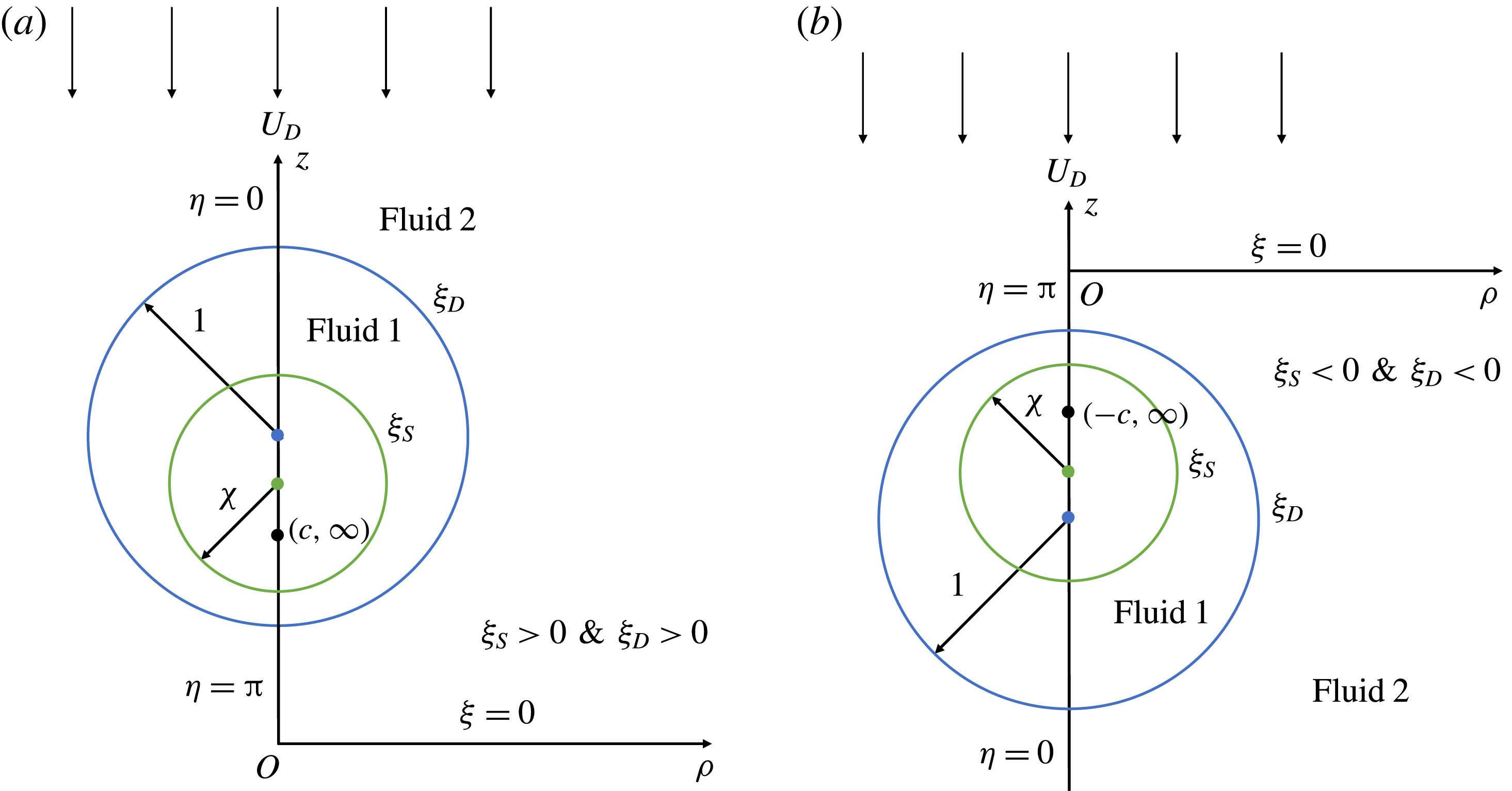
. There are two possibilities for eccentric configurations, namely the swimmer lying above or below the drop. For the swimmer above (below) the drop, we place the origin of the coordinate system above (below) the drop, corresponding to
$\unicode[STIX]{x1D709}=\unicode[STIX]{x1D709}_{D}$
. There are two possibilities for eccentric configurations, namely the swimmer lying above or below the drop. For the swimmer above (below) the drop, we place the origin of the coordinate system above (below) the drop, corresponding to
![]() $\unicode[STIX]{x1D709}_{S}$
and
$\unicode[STIX]{x1D709}_{S}$
and
![]() $\unicode[STIX]{x1D709}_{D}<0$
(
$\unicode[STIX]{x1D709}_{D}<0$
(
![]() $\unicode[STIX]{x1D709}_{S}$
and
$\unicode[STIX]{x1D709}_{S}$
and
![]() $\unicode[STIX]{x1D709}_{D}>0$
) (see figure 2 for the schematic of the problem). Explicit expressions for
$\unicode[STIX]{x1D709}_{D}>0$
) (see figure 2 for the schematic of the problem). Explicit expressions for
![]() $\unicode[STIX]{x1D709}_{S}$
,
$\unicode[STIX]{x1D709}_{S}$
,
![]() $\unicode[STIX]{x1D709}_{D}$
and
$\unicode[STIX]{x1D709}_{D}$
and
![]() $c$
are given as
$c$
are given as
where
![]() $d=|e|$
and
$d=|e|$
and
![]() $e=z_{S}-z_{D}$
. Here,
$e=z_{S}-z_{D}$
. Here,
![]() $z_{S}$
and
$z_{S}$
and
![]() $z_{D}$
denote the
$z_{D}$
denote the
![]() $z$
-coordinates of the centres of the swimmer and the drop respectively. Moreover, a minus (plus) sign should be used for a swimmer located above (below) the drop.
$z$
-coordinates of the centres of the swimmer and the drop respectively. Moreover, a minus (plus) sign should be used for a swimmer located above (below) the drop.
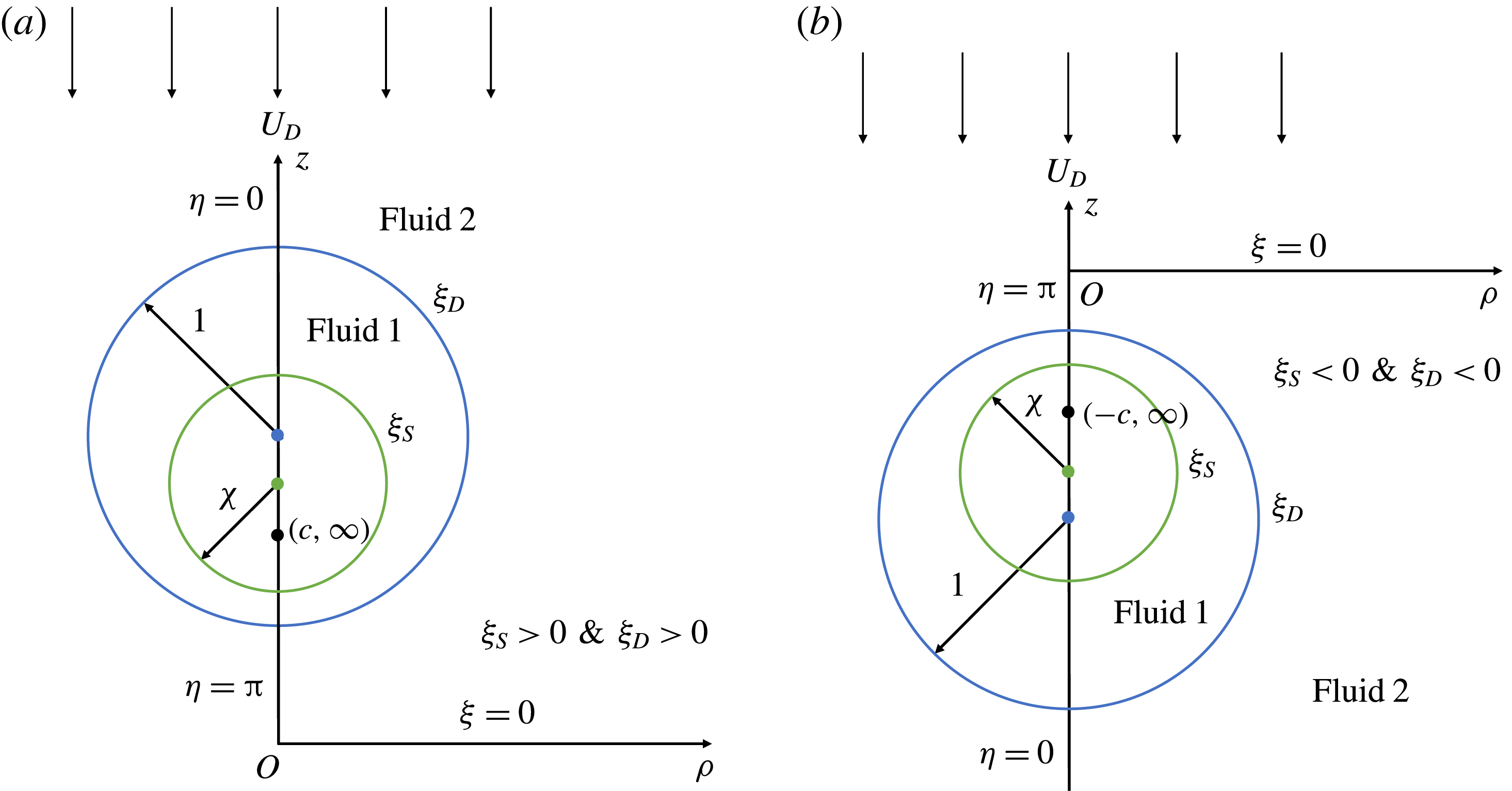
Figure 2. A schematic showing the geometric configuration and its associated coordinate system for (a) the swimmer located below the drop and (b) the swimmer located above the drop. Here,
![]() $(z,\unicode[STIX]{x1D70C})$
and
$(z,\unicode[STIX]{x1D70C})$
and
![]() $(\unicode[STIX]{x1D709},\unicode[STIX]{x1D702})$
denote the coordinate variables of the cylindrical and bipolar coordinate systems respectively;
$(\unicode[STIX]{x1D709},\unicode[STIX]{x1D702})$
denote the coordinate variables of the cylindrical and bipolar coordinate systems respectively;
![]() $O$
is the origin of the coordinate systems and it is located below (above) the drop for a swimmer located below (above) the drop;
$O$
is the origin of the coordinate systems and it is located below (above) the drop for a swimmer located below (above) the drop;
![]() $\unicode[STIX]{x1D709}=\unicode[STIX]{x1D709}_{S}$
and
$\unicode[STIX]{x1D709}=\unicode[STIX]{x1D709}_{S}$
and
![]() $\unicode[STIX]{x1D709}_{D}$
denote the surfaces of the swimmer and the drop;
$\unicode[STIX]{x1D709}_{D}$
denote the surfaces of the swimmer and the drop;
![]() $\unicode[STIX]{x1D709}=0$
denotes the plane
$\unicode[STIX]{x1D709}=0$
denotes the plane
![]() $z=0$
;
$z=0$
;
![]() $\unicode[STIX]{x1D702}=0$
and
$\unicode[STIX]{x1D702}=0$
and
![]() $\unicode[STIX]{x1D702}=\unicode[STIX]{x03C0}$
denote the lines
$\unicode[STIX]{x1D702}=\unicode[STIX]{x03C0}$
denote the lines
![]() $|z|\geqslant c$
and
$|z|\geqslant c$
and
![]() $|z|\leqslant c$
respectively. In the frame of reference of the drop, it is stationary and is placed in a uniform streaming flow,
$|z|\leqslant c$
respectively. In the frame of reference of the drop, it is stationary and is placed in a uniform streaming flow,
![]() $-U_{D}\boldsymbol{i}_{z}$
.
$-U_{D}\boldsymbol{i}_{z}$
.
In the bipolar coordinates, the velocity components are related to the stream function via
where
![]() $h=(\cosh \unicode[STIX]{x1D709}-\cos \unicode[STIX]{x1D702})/c$
is one of the metrical coefficients of the bipolar coordinates. We enforce these relations in the creeping flow equations to derive the dynamic equation for the stream function, given as
$h=(\cosh \unicode[STIX]{x1D709}-\cos \unicode[STIX]{x1D702})/c$
is one of the metrical coefficients of the bipolar coordinates. We enforce these relations in the creeping flow equations to derive the dynamic equation for the stream function, given as
![]() $E^{4}\unicode[STIX]{x1D713}_{j}^{(k)}=0$
, where
$E^{4}\unicode[STIX]{x1D713}_{j}^{(k)}=0$
, where
Similarly, one can express the boundary conditions given by (2.12) and (2.16)–(2.18) in terms of velocity components in bipolar coordinates, which can be eventually written in terms of the stream function using (3.11).
On the swimmer:
On the drop:
 $$\begin{eqnarray}\displaystyle \left.\begin{array}{@{}c@{}}\displaystyle v_{j,\unicode[STIX]{x1D709}}^{(1)}=v_{j,\unicode[STIX]{x1D709}}^{(2)}=0,\\ \displaystyle v_{j,\unicode[STIX]{x1D702}}^{(1)}=v_{j,\unicode[STIX]{x1D702}}^{(2)},\\ \displaystyle -\text{sgn}(\unicode[STIX]{x1D709}_{D})(T_{j,\unicode[STIX]{x1D709}\unicode[STIX]{x1D702}}^{(2)}-\unicode[STIX]{x1D706}T_{j,\unicode[STIX]{x1D709}\unicode[STIX]{x1D702}}^{(1)})=Mah\frac{\text{d}\unicode[STIX]{x1D6E4}_{j}}{\text{d}\unicode[STIX]{x1D702}},\end{array}\right\} & & \displaystyle\end{eqnarray}$$
where
Here,
![]() $\boldsymbol{i}_{\unicode[STIX]{x1D709}}$
and
$\boldsymbol{i}_{\unicode[STIX]{x1D709}}$
and
![]() $\boldsymbol{i}_{\unicode[STIX]{x1D702}}$
are the unit vectors in the increasing direction of
$\boldsymbol{i}_{\unicode[STIX]{x1D702}}$
are the unit vectors in the increasing direction of
![]() $\unicode[STIX]{x1D709}$
and
$\unicode[STIX]{x1D709}$
and
![]() $\unicode[STIX]{x1D702}$
respectively. Moreover,
$\unicode[STIX]{x1D702}$
respectively. Moreover,
![]() $u_{\unicode[STIX]{x1D709}}^{s}$
and
$u_{\unicode[STIX]{x1D709}}^{s}$
and
![]() $u_{\unicode[STIX]{x1D702}}^{s}$
are the components of the swimmer surface velocity in the bipolar coordinates, while
$u_{\unicode[STIX]{x1D702}}^{s}$
are the components of the swimmer surface velocity in the bipolar coordinates, while
![]() $\unicode[STIX]{x1D6FF}_{j,0}$
is the Kronecker delta. We outline the steps used for converting the swimmer surface velocity from the spherical coordinate system to the bipolar coordinate system in appendix D. The far-field condition (2.15) gives the following condition for the stream function (Happel & Brenner Reference Happel and Brenner1983):
$\unicode[STIX]{x1D6FF}_{j,0}$
is the Kronecker delta. We outline the steps used for converting the swimmer surface velocity from the spherical coordinate system to the bipolar coordinate system in appendix D. The far-field condition (2.15) gives the following condition for the stream function (Happel & Brenner Reference Happel and Brenner1983):
Stimson & Jeffery (Reference Stimson and Jeffery1926) derived a general solution of
![]() $E^{4}\unicode[STIX]{x1D713}_{j}^{(k)}=0$
when
$E^{4}\unicode[STIX]{x1D713}_{j}^{(k)}=0$
when
![]() $E^{2}$
is expressed in bipolar coordinates, and it is given as
$E^{2}$
is expressed in bipolar coordinates, and it is given as
where
Here,
![]() $C_{n+1}^{-1/2}(\cos \unicode[STIX]{x1D702})$
is a Gegenbauer polynomial (Whittaker & Watson Reference Whittaker and Watson1996) of order
$C_{n+1}^{-1/2}(\cos \unicode[STIX]{x1D702})$
is a Gegenbauer polynomial (Whittaker & Watson Reference Whittaker and Watson1996) of order
![]() $n+1$
and degree
$n+1$
and degree
![]() $-1/2$
, while
$-1/2$
, while
![]() $A_{j,n}^{(k)}$
,
$A_{j,n}^{(k)}$
,
![]() $B_{j,n}^{(k)}$
,
$B_{j,n}^{(k)}$
,
![]() $C_{j,n}^{(k)}$
and
$C_{j,n}^{(k)}$
and
![]() $D_{j,n}^{(k)}$
are the unknown constants. We substitute (3.17) in the boundary conditions and the far-field condition, written in terms of the stream function, to derive eight linear algebraic equations in the unknowns –
$D_{j,n}^{(k)}$
are the unknown constants. We substitute (3.17) in the boundary conditions and the far-field condition, written in terms of the stream function, to derive eight linear algebraic equations in the unknowns –
![]() $A_{j,n}^{(1)}$
,
$A_{j,n}^{(1)}$
,
![]() $B_{j,n}^{(1)}$
,
$B_{j,n}^{(1)}$
,
![]() $C_{j,n}^{(1)}$
,
$C_{j,n}^{(1)}$
,
![]() $D_{j,n}^{(1)}$
,
$D_{j,n}^{(1)}$
,
![]() $A_{j,n}^{(2)}$
,
$A_{j,n}^{(2)}$
,
![]() $B_{j,n}^{(2)}$
,
$B_{j,n}^{(2)}$
,
![]() $C_{j,n}^{(2)}$
and
$C_{j,n}^{(2)}$
and
![]() $D_{j,n}^{(2)}$
– at each order in
$D_{j,n}^{(2)}$
– at each order in
![]() $Pe_{s}$
and for each
$Pe_{s}$
and for each
![]() $n$
. These equations are summarized in appendix E. We then solve these equations to derive the explicit expressions for the unknowns.
$n$
. These equations are summarized in appendix E. We then solve these equations to derive the explicit expressions for the unknowns.
As outlined in the solution methodology for the concentric configuration, we first need to solve for the surfactant concentration before solving for the flow field at any order in
![]() $Pe_{s}$
. The surfactant concentration at
$Pe_{s}$
. The surfactant concentration at
![]() $O(1)$
is uniform and hence it is a known quantity. Since we are solving the flow field up to
$O(1)$
is uniform and hence it is a known quantity. Since we are solving the flow field up to
![]() $O(Pe_{s})$
, we need to find the surfactant concentration at
$O(Pe_{s})$
, we need to find the surfactant concentration at
![]() $O(Pe_{s})$
by solving the corresponding surfactant transport equation, (2.20). Using the definition of the surface gradient operator in bipolar coordinates,
$O(Pe_{s})$
by solving the corresponding surfactant transport equation, (2.20). Using the definition of the surface gradient operator in bipolar coordinates,
![]() $\unicode[STIX]{x1D735}_{s}=\boldsymbol{i}_{\unicode[STIX]{x1D702}}h(\unicode[STIX]{x2202}/\unicode[STIX]{x2202}\unicode[STIX]{x1D702})+\boldsymbol{i}_{\unicode[STIX]{x1D719}}(1/\unicode[STIX]{x1D70C})(\unicode[STIX]{x2202}/\unicode[STIX]{x2202}\unicode[STIX]{x1D719})$
, we simplify the surfactant transport equation at
$\unicode[STIX]{x1D735}_{s}=\boldsymbol{i}_{\unicode[STIX]{x1D702}}h(\unicode[STIX]{x2202}/\unicode[STIX]{x2202}\unicode[STIX]{x1D702})+\boldsymbol{i}_{\unicode[STIX]{x1D719}}(1/\unicode[STIX]{x1D70C})(\unicode[STIX]{x2202}/\unicode[STIX]{x2202}\unicode[STIX]{x1D719})$
, we simplify the surfactant transport equation at
![]() $O(Pe_{s})$
as follows:
$O(Pe_{s})$
as follows:
This equation can be easily integrated with respect to
![]() $\unicode[STIX]{x1D702}$
to obtain
$\unicode[STIX]{x1D702}$
to obtain
![]() $h(\text{d}\unicode[STIX]{x1D6E4}_{1}/\text{d}\unicode[STIX]{x1D702})=v_{0,\unicode[STIX]{x1D702}}^{(1)}(\unicode[STIX]{x1D709}=\unicode[STIX]{x1D709}_{D})=v_{0,\unicode[STIX]{x1D702}}^{(2)}(\unicode[STIX]{x1D709}=\unicode[STIX]{x1D709}_{D})$
. Since only the gradient of the surfactant concentration affects the flow field, through the shear-stress boundary condition, (2.18), we use the above equation to rewrite the shear-stress boundary condition at
$h(\text{d}\unicode[STIX]{x1D6E4}_{1}/\text{d}\unicode[STIX]{x1D702})=v_{0,\unicode[STIX]{x1D702}}^{(1)}(\unicode[STIX]{x1D709}=\unicode[STIX]{x1D709}_{D})=v_{0,\unicode[STIX]{x1D702}}^{(2)}(\unicode[STIX]{x1D709}=\unicode[STIX]{x1D709}_{D})$
. Since only the gradient of the surfactant concentration affects the flow field, through the shear-stress boundary condition, (2.18), we use the above equation to rewrite the shear-stress boundary condition at
![]() $O(Pe_{s})$
as follows:
$O(Pe_{s})$
as follows:
Therefore, once the flow field at
![]() $O(1)$
is known, we can directly evaluate the flow field at
$O(1)$
is known, we can directly evaluate the flow field at
![]() $O(Pe_{s})$
without finding the surfactant concentration at
$O(Pe_{s})$
without finding the surfactant concentration at
![]() $O(Pe_{s})$
. Mandal et al. (Reference Mandal, Ghosh and Chakraborty2016) provided a similar procedure for finding the flow field due to weakly deforming surfactant-laden compound drops. We used this method to derive the linear algebraic equations in the unknown coefficients provided in appendix E.
$O(Pe_{s})$
. Mandal et al. (Reference Mandal, Ghosh and Chakraborty2016) provided a similar procedure for finding the flow field due to weakly deforming surfactant-laden compound drops. We used this method to derive the linear algebraic equations in the unknown coefficients provided in appendix E.
The solution of the linear algebraic equations provided in appendix E furnishes the explicit expressions for the unknown coefficients in
![]() $W_{j,n}^{(k)}$
. These coefficients are linear in the swimmer and drop velocities at any order in
$W_{j,n}^{(k)}$
. These coefficients are linear in the swimmer and drop velocities at any order in
![]() $Pe_{s}$
. For instance, the coefficient
$Pe_{s}$
. For instance, the coefficient
![]() $A_{j,n}^{(k)}$
is given as
$A_{j,n}^{(k)}$
is given as
where
![]() $Q_{j,n}^{(k)}$
,
$Q_{j,n}^{(k)}$
,
![]() $R_{j,n}^{(k)}$
and
$R_{j,n}^{(k)}$
and
![]() $S_{j,n}^{(k)}$
are the functions of
$S_{j,n}^{(k)}$
are the functions of
![]() $\unicode[STIX]{x1D712}$
,
$\unicode[STIX]{x1D712}$
,
![]() $\unicode[STIX]{x1D706}$
and
$\unicode[STIX]{x1D706}$
and
![]() $Ma$
. We then impose the force-free conditions for the swimmer and the drop, given as (Stimson & Jeffery Reference Stimson and Jeffery1926; Brenner Reference Brenner1961; Rushton & Davies Reference Rushton and Davies1973; Happel & Brenner Reference Happel and Brenner1983)
$Ma$
. We then impose the force-free conditions for the swimmer and the drop, given as (Stimson & Jeffery Reference Stimson and Jeffery1926; Brenner Reference Brenner1961; Rushton & Davies Reference Rushton and Davies1973; Happel & Brenner Reference Happel and Brenner1983)
We solve these two equations to find the swimmer and drop velocities at any order in
![]() $Pe_{s}$
. Since these two equations contain an infinite number of coefficients, we truncate this sum to a finite number
$Pe_{s}$
. Since these two equations contain an infinite number of coefficients, we truncate this sum to a finite number
![]() $N$
such that the error in the evaluation of the swimmer and drop velocities is less than
$N$
such that the error in the evaluation of the swimmer and drop velocities is less than
![]() $10^{-6}$
.
$10^{-6}$
.
4 Results and discussion
We note that the formulation provided in the previous two sections is entirely general as long as the swimmer surface velocity
![]() $\boldsymbol{u}^{s}$
is axisymmetric. To perform further analysis, we need to choose a specific functional form for
$\boldsymbol{u}^{s}$
is axisymmetric. To perform further analysis, we need to choose a specific functional form for
![]() $\boldsymbol{u}^{s}$
. For this purpose, we model the swimmer as a ‘squirmer’ having both radial and tangential modes. Such a model is used to describe the ciliated microorganisms that propel through the metachronal beating of flexible cilia on their surface. According to this model (Lighthill Reference Lighthill1952; Blake Reference Blake1971), one does not worry about the individual cilia but instead applies a boundary condition for the velocity on a spherical surface that encompasses the cilia. Hence, the slip velocity on the squirmer surface,
$\boldsymbol{u}^{s}$
. For this purpose, we model the swimmer as a ‘squirmer’ having both radial and tangential modes. Such a model is used to describe the ciliated microorganisms that propel through the metachronal beating of flexible cilia on their surface. According to this model (Lighthill Reference Lighthill1952; Blake Reference Blake1971), one does not worry about the individual cilia but instead applies a boundary condition for the velocity on a spherical surface that encompasses the cilia. Hence, the slip velocity on the squirmer surface,
![]() $\boldsymbol{u}^{s}$
, is given as
$\boldsymbol{u}^{s}$
, is given as
where
![]() $\boldsymbol{i}_{r}$
and
$\boldsymbol{i}_{r}$
and
![]() $\boldsymbol{i}_{\unicode[STIX]{x1D703}}$
are the unit vectors in the radial and polar directions with the origin located at the centre of the squirmer, while
$\boldsymbol{i}_{\unicode[STIX]{x1D703}}$
are the unit vectors in the radial and polar directions with the origin located at the centre of the squirmer, while
![]() $A_{n}$
and
$A_{n}$
and
![]() $B_{n}$
are known constants, the so-called modes of a squirmer. We, however, do not consider the
$B_{n}$
are known constants, the so-called modes of a squirmer. We, however, do not consider the
![]() $A_{0}$
mode since there is no solution of the governing equations satisfying all of the boundary conditions when such a swimmer (squirmer having only an
$A_{0}$
mode since there is no solution of the governing equations satisfying all of the boundary conditions when such a swimmer (squirmer having only an
![]() $A_{0}$
mode) is located inside a drop. A squirmer possessing only the tangential squirming modes moves with a speed of
$A_{0}$
mode) is located inside a drop. A squirmer possessing only the tangential squirming modes moves with a speed of
![]() $U_{sq}=2B_{1}/3$
in an unbounded quiescent fluid, and we can represent the flow field far away from it by placing a force dipole at its centre, the strength of which depends on the
$U_{sq}=2B_{1}/3$
in an unbounded quiescent fluid, and we can represent the flow field far away from it by placing a force dipole at its centre, the strength of which depends on the
![]() $B_{2}$
mode. Since the swimming velocity and the far-field hydrodynamics are dictated by only the
$B_{2}$
mode. Since the swimming velocity and the far-field hydrodynamics are dictated by only the
![]() $B_{1}$
and
$B_{1}$
and
![]() $B_{2}$
modes, we can discard all other modes and study the hydrodynamics of this two-mode squirmer whose flow field is characterized by a single parameter,
$B_{2}$
modes, we can discard all other modes and study the hydrodynamics of this two-mode squirmer whose flow field is characterized by a single parameter,
![]() $\unicode[STIX]{x1D6FD}=B_{2}/B_{1}$
. Swimmers possessing
$\unicode[STIX]{x1D6FD}=B_{2}/B_{1}$
. Swimmers possessing
![]() $\unicode[STIX]{x1D6FD}<0$
are called pushers and they swim by repelling fluid along their axis while drawing fluid along their sides. Swimmers having
$\unicode[STIX]{x1D6FD}<0$
are called pushers and they swim by repelling fluid along their axis while drawing fluid along their sides. Swimmers having
![]() $\unicode[STIX]{x1D6FD}>0$
are called pullers and they swim by repelling fluid along their sides while drawing fluid along their axis. Swimmers having
$\unicode[STIX]{x1D6FD}>0$
are called pullers and they swim by repelling fluid along their sides while drawing fluid along their axis. Swimmers having
![]() $\unicode[STIX]{x1D6FD}=0$
are called neutral swimmers and their flow field is represented by a degenerate quadrupole placed at the centre of the squirmer. Due to its mathematical simplicity, the two-mode squirmer model has been used extensively in the literature to study several physical processes involving microswimmers (Ishikawa, Simmonds & Pedley Reference Ishikawa, Simmonds and Pedley2006; Short et al.
Reference Short, Solari, Ganguly, Powers, Kessler and Goldstein2006; Doostmohammadi, Stocker & Ardekani Reference Doostmohammadi, Stocker and Ardekani2012; Shaik & Ardekani Reference Shaik and Ardekani2017a
). For this reason, we present most of our results for this two-mode squirmer. The analyses in §§ 4.1.1, 4.1.2, 4.1.3, 4.2, 4.3 and 4.4 are carried out for a two-mode squirmer, while the analysis in § 4.1.4 is valid for a three-mode squirmer possessing
$\unicode[STIX]{x1D6FD}=0$
are called neutral swimmers and their flow field is represented by a degenerate quadrupole placed at the centre of the squirmer. Due to its mathematical simplicity, the two-mode squirmer model has been used extensively in the literature to study several physical processes involving microswimmers (Ishikawa, Simmonds & Pedley Reference Ishikawa, Simmonds and Pedley2006; Short et al.
Reference Short, Solari, Ganguly, Powers, Kessler and Goldstein2006; Doostmohammadi, Stocker & Ardekani Reference Doostmohammadi, Stocker and Ardekani2012; Shaik & Ardekani Reference Shaik and Ardekani2017a
). For this reason, we present most of our results for this two-mode squirmer. The analyses in §§ 4.1.1, 4.1.2, 4.1.3, 4.2, 4.3 and 4.4 are carried out for a two-mode squirmer, while the analysis in § 4.1.4 is valid for a three-mode squirmer possessing
![]() $A_{1}$
,
$A_{1}$
,
![]() $B_{1}$
and
$B_{1}$
and
![]() $B_{2}$
modes. For a swimmer at the centre of the drop, since the velocities of the swimmer and the drop depend only on
$B_{2}$
modes. For a swimmer at the centre of the drop, since the velocities of the swimmer and the drop depend only on
![]() $A_{1}$
and
$A_{1}$
and
![]() $B_{1}$
modes, we note that the results and discussion provided in § 4.1.1 (§ 4.1.4) are valid for a swimmer with more general boundary conditions – a swimmer with ‘
$B_{1}$
modes, we note that the results and discussion provided in § 4.1.1 (§ 4.1.4) are valid for a swimmer with more general boundary conditions – a swimmer with ‘
![]() $n$
’ tangential squirming modes (a swimmer with both tangential and radial squirming modes as long as the
$n$
’ tangential squirming modes (a swimmer with both tangential and radial squirming modes as long as the
![]() $A_{1}$
mode is chosen according to (4.18)).
$A_{1}$
mode is chosen according to (4.18)).
We recall the perturbation scheme,
![]() $\boldsymbol{v}=\boldsymbol{v}_{0}+Pe_{s}\boldsymbol{v}_{1}+O(Pe_{s}^{2})$
. Since
$\boldsymbol{v}=\boldsymbol{v}_{0}+Pe_{s}\boldsymbol{v}_{1}+O(Pe_{s}^{2})$
. Since
![]() $\boldsymbol{v}_{1}\propto Ma$
, we can write
$\boldsymbol{v}_{1}\propto Ma$
, we can write ![]() , hence
, hence ![]() . In our case,
. In our case, ![]() is at most
is at most
![]() $O(0.1)$
(for instance, see figure 5(b) for the
$O(0.1)$
(for instance, see figure 5(b) for the
![]() $O(Pe_{s})$
flow field due to a pusher swimmer at the centre of the drop at
$O(Pe_{s})$
flow field due to a pusher swimmer at the centre of the drop at
![]() $Ma=1$
). Therefore, for small-
$Ma=1$
). Therefore, for small-
![]() $Pe_{s}$
analysis to be valid,
$Pe_{s}$
analysis to be valid,
![]() $Ma$
can be at most
$Ma$
can be at most
![]() $O(10)$
.
$O(10)$
.
We give a justification for the range of parameter values used in this paper. We assume that water droplets are immersed in oil and take the viscosity of oil to lie in the range
![]() $0.1\unicode[STIX]{x1D707}_{water}$
–
$0.1\unicode[STIX]{x1D707}_{water}$
–
![]() $10\unicode[STIX]{x1D707}_{water}$
, where
$10\unicode[STIX]{x1D707}_{water}$
, where
![]() $\unicode[STIX]{x1D707}_{water}$
is the dynamic viscosity of the water. Therefore,
$\unicode[STIX]{x1D707}_{water}$
is the dynamic viscosity of the water. Therefore,
![]() $\unicode[STIX]{x1D706}$
lies in between 0.1 and 10. This assumption of water in oil drops is in accordance with the experiments of Ding et al. (Reference Ding, Qiu, Casadevall i Solvas, Chiu, Nelson and Demello2016), where
$\unicode[STIX]{x1D706}$
lies in between 0.1 and 10. This assumption of water in oil drops is in accordance with the experiments of Ding et al. (Reference Ding, Qiu, Casadevall i Solvas, Chiu, Nelson and Demello2016), where
![]() $\unicode[STIX]{x1D707}_{oil}=4.6\unicode[STIX]{x1D707}_{water}$
(for FC-40) also lies in the range of oil viscosities used in this paper. We take the size ratio,
$\unicode[STIX]{x1D707}_{oil}=4.6\unicode[STIX]{x1D707}_{water}$
(for FC-40) also lies in the range of oil viscosities used in this paper. We take the size ratio,
![]() $\unicode[STIX]{x1D712}$
, to lie in the range 0–1, where
$\unicode[STIX]{x1D712}$
, to lie in the range 0–1, where
![]() $\unicode[STIX]{x1D712}\ll 1$
means that the size of the swimmer is much smaller than the drop size (this is similar to the experiments (Ding et al.
Reference Ding, Qiu, Casadevall i Solvas, Chiu, Nelson and Demello2016)). On the other hand,
$\unicode[STIX]{x1D712}\ll 1$
means that the size of the swimmer is much smaller than the drop size (this is similar to the experiments (Ding et al.
Reference Ding, Qiu, Casadevall i Solvas, Chiu, Nelson and Demello2016)). On the other hand,
![]() $\unicode[STIX]{x1D712}\rightarrow 1$
means that the swimmer and the drop are approximately of the same size. We note that the speed of an E. coli or an ABF in an unbounded fluid is
$\unicode[STIX]{x1D712}\rightarrow 1$
means that the swimmer and the drop are approximately of the same size. We note that the speed of an E. coli or an ABF in an unbounded fluid is
![]() $U_{sq}\approx 10~\unicode[STIX]{x03BC}\text{m}~\text{s}^{-1}$
(Lauga & Powers Reference Lauga and Powers2009; Ding et al.
Reference Ding, Qiu, Casadevall i Solvas, Chiu, Nelson and Demello2016). Since the size of an E. coli or ABF is (Lauga & Powers Reference Lauga and Powers2009; Ding et al.
Reference Ding, Qiu, Casadevall i Solvas, Chiu, Nelson and Demello2016)
$U_{sq}\approx 10~\unicode[STIX]{x03BC}\text{m}~\text{s}^{-1}$
(Lauga & Powers Reference Lauga and Powers2009; Ding et al.
Reference Ding, Qiu, Casadevall i Solvas, Chiu, Nelson and Demello2016). Since the size of an E. coli or ABF is (Lauga & Powers Reference Lauga and Powers2009; Ding et al.
Reference Ding, Qiu, Casadevall i Solvas, Chiu, Nelson and Demello2016)
![]() $1{-}10~\unicode[STIX]{x03BC}\text{m}$
, we take the size of the drop to lie in the range
$1{-}10~\unicode[STIX]{x03BC}\text{m}$
, we take the size of the drop to lie in the range
![]() $a\approx 1{-}100~\unicode[STIX]{x03BC}\text{m}$
. Moreover, we choose the equilibrium surfactant concentration and the surface diffusivity of the surfactant to lie in the ranges (Ramirez & Davis Reference Ramirez and Davis1999)
$a\approx 1{-}100~\unicode[STIX]{x03BC}\text{m}$
. Moreover, we choose the equilibrium surfactant concentration and the surface diffusivity of the surfactant to lie in the ranges (Ramirez & Davis Reference Ramirez and Davis1999)
![]() $\unicode[STIX]{x1D6E4}_{eq}\approx 10^{-13}$
–
$\unicode[STIX]{x1D6E4}_{eq}\approx 10^{-13}$
–
![]() $10^{-10}~\text{mol}~\text{cm}^{-2}$
and
$10^{-10}~\text{mol}~\text{cm}^{-2}$
and
![]() $D_{s}\approx 10^{-6}$
–
$D_{s}\approx 10^{-6}$
–
![]() $10^{-5}~\text{cm}^{2}~\text{s}^{-1}$
. Using these parameter values, we determine the surface Péclet number and the Marangoni number to lie in the ranges
$10^{-5}~\text{cm}^{2}~\text{s}^{-1}$
. Using these parameter values, we determine the surface Péclet number and the Marangoni number to lie in the ranges
![]() $Pe_{s}\approx O(10^{-2}{-}10)$
and
$Pe_{s}\approx O(10^{-2}{-}10)$
and
![]() $Ma\approx O(10{-}10^{6})$
. Noting that
$Ma\approx O(10{-}10^{6})$
. Noting that
![]() $\unicode[STIX]{x1D6E4}_{eq}=0$
or
$\unicode[STIX]{x1D6E4}_{eq}=0$
or
![]() $Ma=0$
for a clean drop, we extend the range of Marangoni number to
$Ma=0$
for a clean drop, we extend the range of Marangoni number to
![]() $Ma\approx 0$
–
$Ma\approx 0$
–
![]() $O(10^{6})$
so as to include the scenarios of a clean drop or very small surfactant concentrations. As a small-surface-Péclet calculation is made in this paper, we choose
$O(10^{6})$
so as to include the scenarios of a clean drop or very small surfactant concentrations. As a small-surface-Péclet calculation is made in this paper, we choose
![]() $Pe_{s}\approx O(10^{-2}{-}10^{-1})$
and
$Pe_{s}\approx O(10^{-2}{-}10^{-1})$
and
![]() $Ma\approx 0$
–
$Ma\approx 0$
–
![]() $O(10)$
.
$O(10)$
.
4.1 Concentric configuration
4.1.1 Swimmer and drop velocities
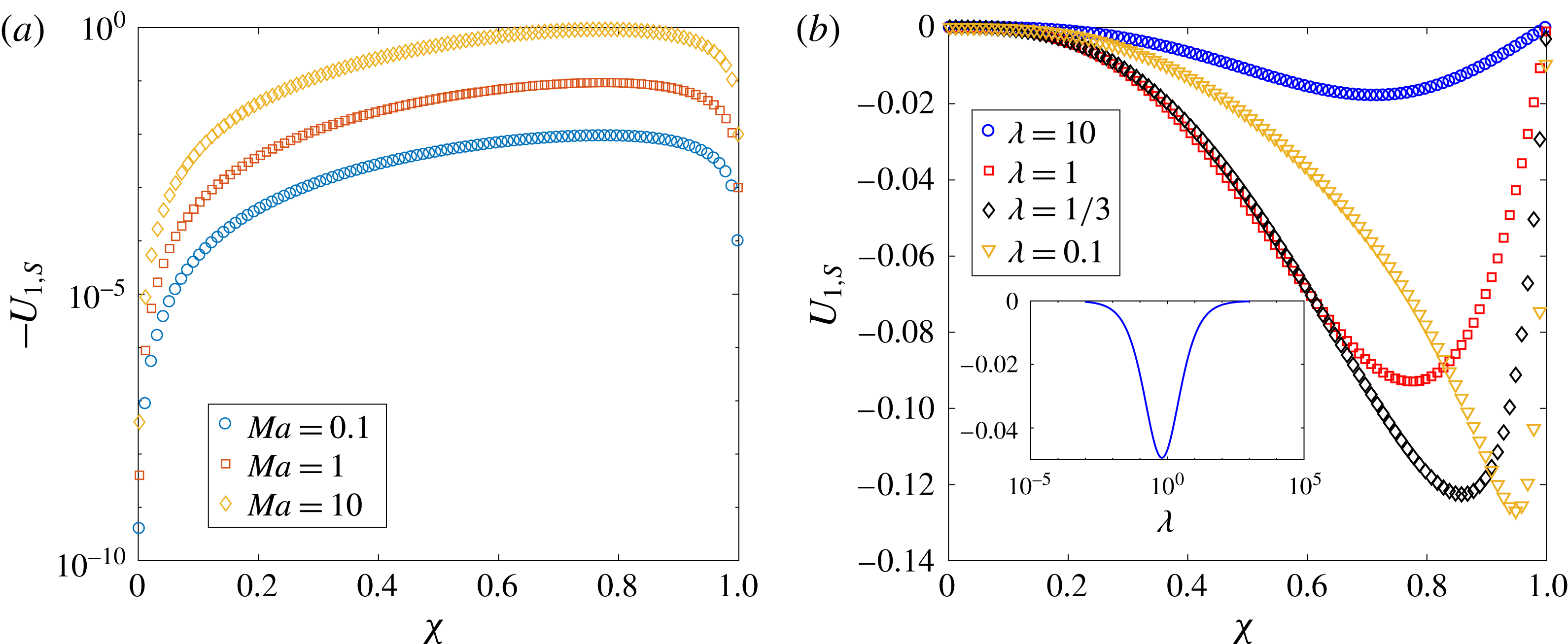
The swimmer and drop velocities accurate to
![]() $O(Pe_{s})$
are given as (noting that
$O(Pe_{s})$
are given as (noting that
![]() $\boldsymbol{U}_{S}=U_{S}\boldsymbol{i}_{z},\boldsymbol{U}_{j,S}=U_{j,S}\boldsymbol{i}_{z},\boldsymbol{U}_{D}=U_{D}\boldsymbol{i}_{z},\boldsymbol{U}_{j,D}=U_{j,D}\boldsymbol{i}_{z}$
)
$\boldsymbol{U}_{S}=U_{S}\boldsymbol{i}_{z},\boldsymbol{U}_{j,S}=U_{j,S}\boldsymbol{i}_{z},\boldsymbol{U}_{D}=U_{D}\boldsymbol{i}_{z},\boldsymbol{U}_{j,D}=U_{j,D}\boldsymbol{i}_{z}$
)
When the drop and the swimmer are in a concentric configuration, the expressions for
![]() $U_{0,S}$
,
$U_{0,S}$
,
![]() $U_{1,S}$
,
$U_{1,S}$
,
![]() $U_{0,D}$
and
$U_{0,D}$
and
![]() $U_{1,D}$
for a general
$U_{1,D}$
for a general
![]() $n$
-mode squirmer inside a drop are given as (see (B 13), (B 14), (B 28), and (B 29))
$n$
-mode squirmer inside a drop are given as (see (B 13), (B 14), (B 28), and (B 29))
Our expressions for
![]() $U_{0,S}$
and
$U_{0,S}$
and
![]() $U_{0,D}$
match with the corresponding expressions derived for the motion of a swimmer inside a clean drop (Reigh et al.
Reference Reigh, Zhu, Gallaire and Lauga2017). We note that the swimmer and drop velocities at
$U_{0,D}$
match with the corresponding expressions derived for the motion of a swimmer inside a clean drop (Reigh et al.
Reference Reigh, Zhu, Gallaire and Lauga2017). We note that the swimmer and drop velocities at
![]() $O(1)$
and at
$O(1)$
and at
![]() $O(Pe_{s})$
depend only on
$O(Pe_{s})$
depend only on
![]() $A_{1}$
and
$A_{1}$
and
![]() $B_{1}$
modes. Moreover, since
$B_{1}$
modes. Moreover, since
![]() $0<\unicode[STIX]{x1D712}<1$
, it can be clearly seen that for positive values of
$0<\unicode[STIX]{x1D712}<1$
, it can be clearly seen that for positive values of
![]() $A_{1}$
and
$A_{1}$
and
![]() $B_{1}$
,
$B_{1}$
,
![]() $U_{1,S}\leqslant 0$
and
$U_{1,S}\leqslant 0$
and
![]() $U_{1,D}\leqslant 0$
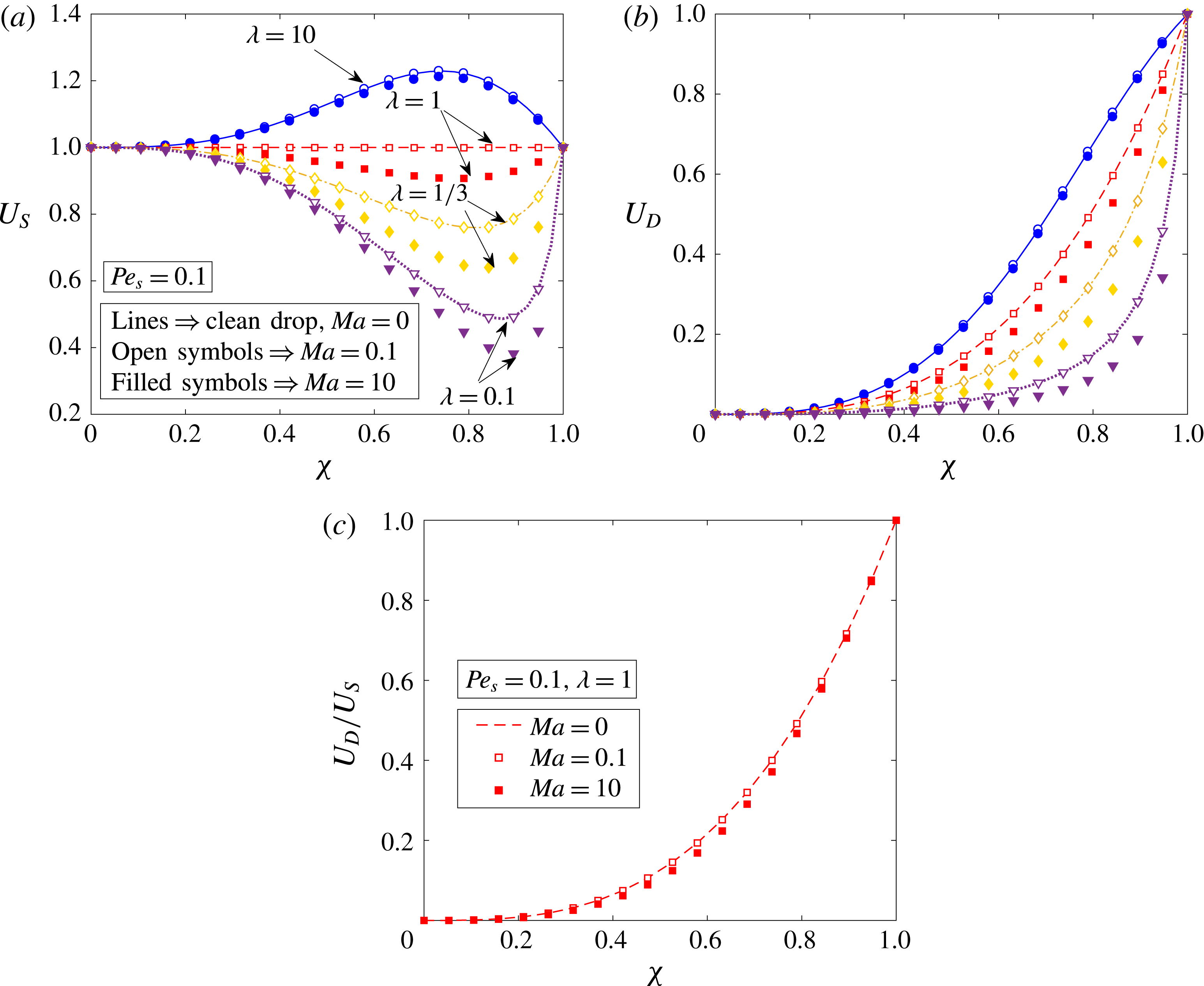
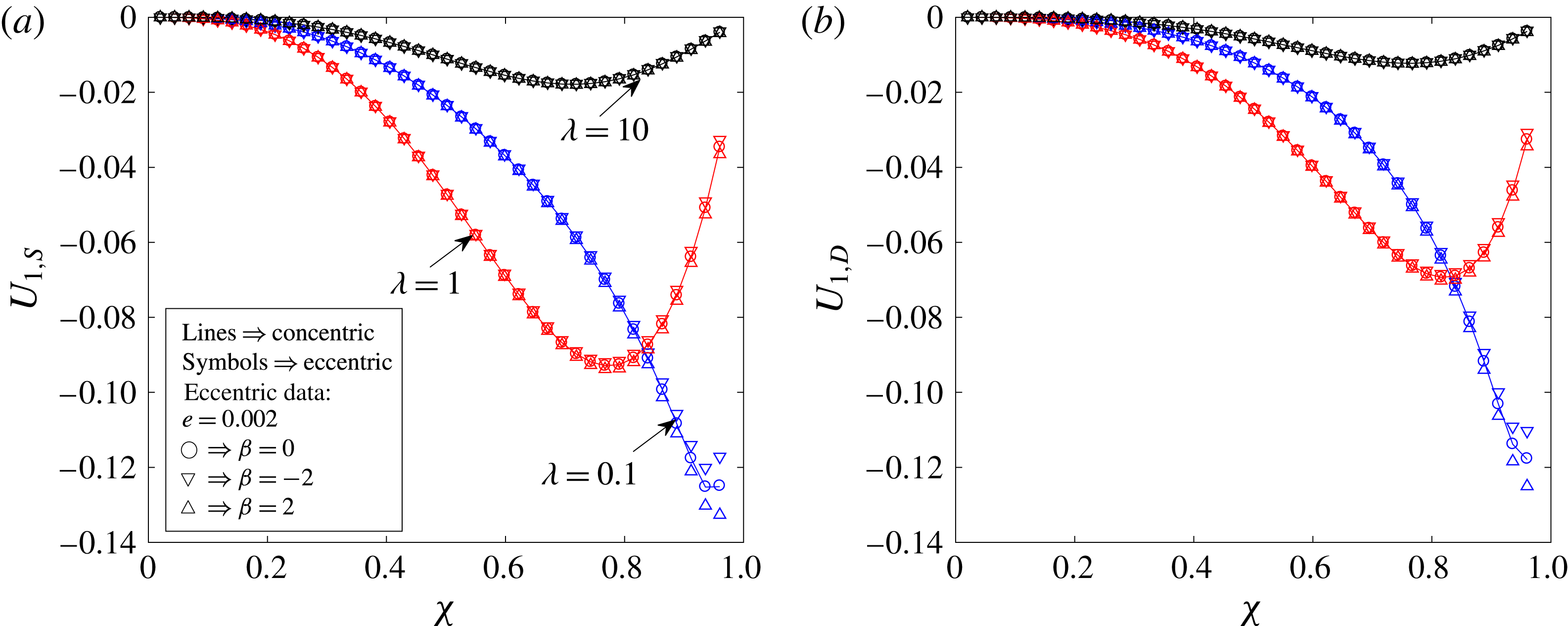
. We plot in figure 3 the swimmer and drop velocities accurate to
$U_{1,D}\leqslant 0$
. We plot in figure 3 the swimmer and drop velocities accurate to
![]() $O(Pe_{s})$
for various values of the size ratio
$O(Pe_{s})$
for various values of the size ratio
![]() $\unicode[STIX]{x1D712}$
, the viscosity ratio
$\unicode[STIX]{x1D712}$
, the viscosity ratio
![]() $\unicode[STIX]{x1D706}$
and the Marangoni number
$\unicode[STIX]{x1D706}$
and the Marangoni number
![]() $Ma$
. Even though the expressions for the swimmer and drop velocities accurate to
$Ma$
. Even though the expressions for the swimmer and drop velocities accurate to
![]() $O(Pe_{s})$
are valid for an
$O(Pe_{s})$
are valid for an
![]() $n$
-mode squirmer, we plot these velocities for a two-mode squirmer inside a drop in figure 3. In this case, the swimmer and drop velocities are always positive if the drop is clean. Since
$n$
-mode squirmer, we plot these velocities for a two-mode squirmer inside a drop in figure 3. In this case, the swimmer and drop velocities are always positive if the drop is clean. Since
![]() $U_{1,S},U_{1,D}\leqslant 0$
while
$U_{1,S},U_{1,D}\leqslant 0$
while
![]() $U_{0,S},U_{0,D}\geqslant 0$
for a two-mode squirmer inside a drop, the leading-order effect of the surfactant is to reduce the swimmer and drop velocities. This can be seen from figure 3, where the swimmer and drop velocities for a surfactant-laden drop (symbols) are less than the corresponding velocities for a clean drop (lines).
$U_{0,S},U_{0,D}\geqslant 0$
for a two-mode squirmer inside a drop, the leading-order effect of the surfactant is to reduce the swimmer and drop velocities. This can be seen from figure 3, where the swimmer and drop velocities for a surfactant-laden drop (symbols) are less than the corresponding velocities for a clean drop (lines).
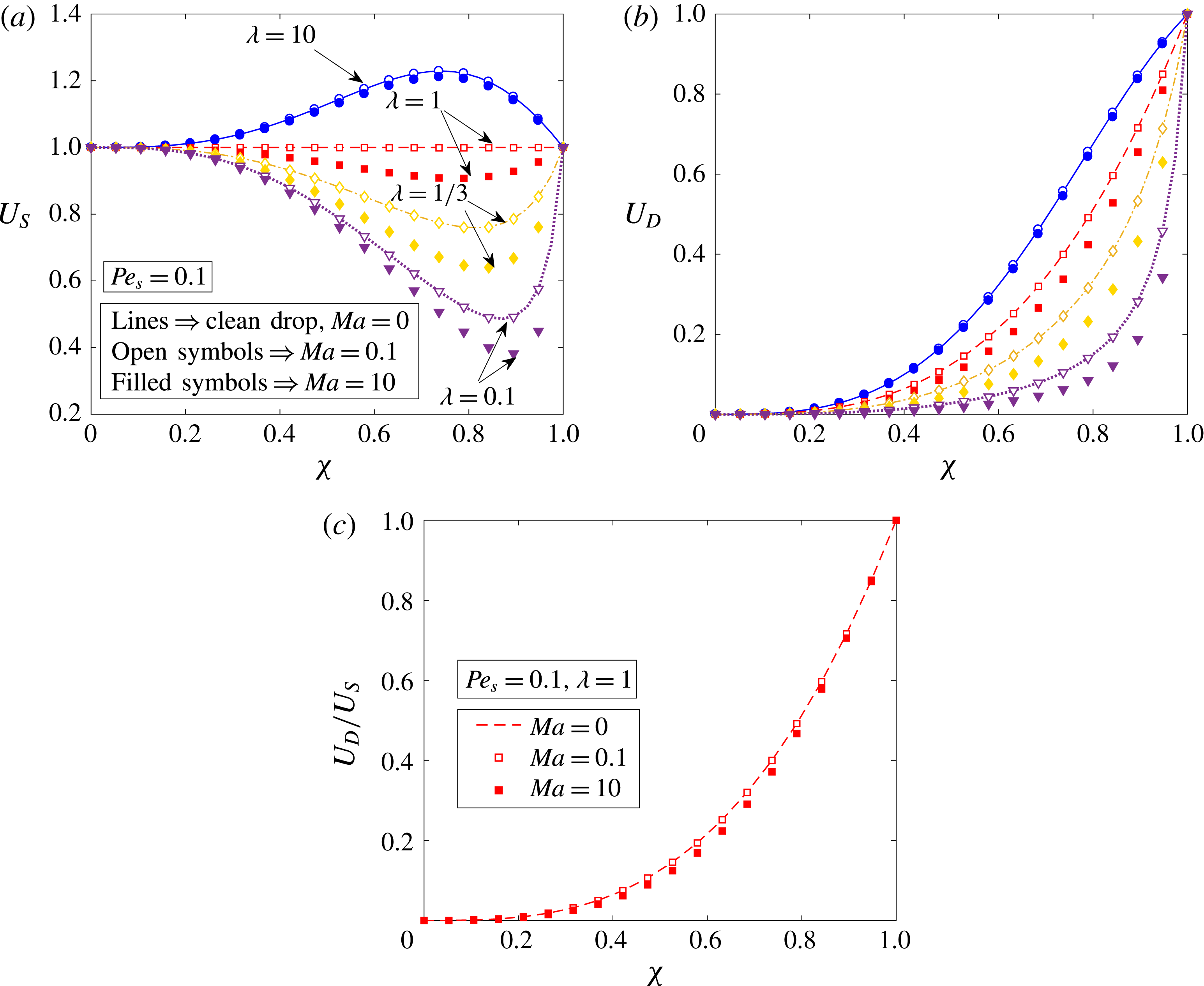
Figure 3. Velocity of (a) a two-mode squirmer,
![]() $U_{S}$
, and (b) a drop,
$U_{S}$
, and (b) a drop,
![]() $U_{D}$
, as a function of the size ratio
$U_{D}$
, as a function of the size ratio
![]() $\unicode[STIX]{x1D712}$
for various values of the viscosity ratio
$\unicode[STIX]{x1D712}$
for various values of the viscosity ratio
![]() $\unicode[STIX]{x1D706}$
and
$\unicode[STIX]{x1D706}$
and
![]() $Ma$
. The variation of
$Ma$
. The variation of
![]() $U_{D}/U_{S}$
with the size ratio
$U_{D}/U_{S}$
with the size ratio
![]() $\unicode[STIX]{x1D712}$
and Marangoni number is plotted in (c) for
$\unicode[STIX]{x1D712}$
and Marangoni number is plotted in (c) for
![]() $\unicode[STIX]{x1D706}=1$
. The lines denote the velocities evaluated for a clean drop, while the open and filled symbols denote the velocities evaluated for a surfactant-laden drop with
$\unicode[STIX]{x1D706}=1$
. The lines denote the velocities evaluated for a clean drop, while the open and filled symbols denote the velocities evaluated for a surfactant-laden drop with
![]() $Ma=0.1$
and 10 respectively. The surface Péclet number,
$Ma=0.1$
and 10 respectively. The surface Péclet number,
![]() $Pe_{s}$
, is chosen as 0.1 in all of these calculations. All of the velocities are non-dimensionalized using
$Pe_{s}$
, is chosen as 0.1 in all of these calculations. All of the velocities are non-dimensionalized using
![]() $U_{sq}=2B_{1}/3$
.
$U_{sq}=2B_{1}/3$
.
We hereby compare the swimmer and drop velocities for a surfactant-covered drop with those of a clean drop. However, first, we make the following observations that hold irrespective of the presence of the surfactant on the drop surface. The swimmer and drop velocities decrease with decreasing viscosity ratio,
![]() $\unicode[STIX]{x1D706}$
. Moreover, the drop velocity decreases with decreasing size ratio,
$\unicode[STIX]{x1D706}$
. Moreover, the drop velocity decreases with decreasing size ratio,
![]() $\unicode[STIX]{x1D712}$
. When the size of the swimmer is much less than the size of the drop (
$\unicode[STIX]{x1D712}$
. When the size of the swimmer is much less than the size of the drop (
![]() $\unicode[STIX]{x1D712}\ll 1$
) or when it is approximately the same as the drop size (
$\unicode[STIX]{x1D712}\ll 1$
) or when it is approximately the same as the drop size (
![]() $\unicode[STIX]{x1D712}\approx 1$
), the swimmer velocity is equal to its velocity in an unbounded medium. Similarly, the drop velocity is zero when
$\unicode[STIX]{x1D712}\approx 1$
), the swimmer velocity is equal to its velocity in an unbounded medium. Similarly, the drop velocity is zero when
![]() $\unicode[STIX]{x1D712}\ll 1$
and it is equal to the velocity of the swimmer in an unbounded medium when
$\unicode[STIX]{x1D712}\ll 1$
and it is equal to the velocity of the swimmer in an unbounded medium when
![]() $\unicode[STIX]{x1D712}\approx 1$
. The surfactant does not affect the swimmer and drop velocities in the limits of
$\unicode[STIX]{x1D712}\approx 1$
. The surfactant does not affect the swimmer and drop velocities in the limits of
![]() $\unicode[STIX]{x1D712}\ll 1$
or
$\unicode[STIX]{x1D712}\ll 1$
or
![]() $\unicode[STIX]{x1D712}\approx 1$
because
$\unicode[STIX]{x1D712}\approx 1$
because
![]() $U_{1,S}=U_{1,D}=0$
in these limits. The swimmer velocity exhibits a maximum (minimum) for those viscosity ratios at which it moves faster (slower) than that in an unbounded fluid.
$U_{1,S}=U_{1,D}=0$
in these limits. The swimmer velocity exhibits a maximum (minimum) for those viscosity ratios at which it moves faster (slower) than that in an unbounded fluid.
One feature that distinguishes the swimmer velocity in a clean drop from that inside a surfactant-laden drop is the viscosity ratio at which the swimmer velocity equals its velocity in an unbounded medium for all size ratios. For instance, we consider the swimmer inside a clean drop. It moves with its velocity in an unbounded medium when
![]() $\unicode[STIX]{x1D706}=1$
(the viscosity of the drop is the same as that of the suspended fluid), whereas it propels with a speed smaller (larger) than its unbounded swimming speed when
$\unicode[STIX]{x1D706}=1$
(the viscosity of the drop is the same as that of the suspended fluid), whereas it propels with a speed smaller (larger) than its unbounded swimming speed when
![]() $\unicode[STIX]{x1D706}<1$
(
$\unicode[STIX]{x1D706}<1$
(
![]() $\unicode[STIX]{x1D706}>1$
). Notably,
$\unicode[STIX]{x1D706}>1$
). Notably,
![]() $\unicode[STIX]{x1D706}=1$
demarcates the
$\unicode[STIX]{x1D706}=1$
demarcates the
![]() $U_{S}>1$
region (faster swimming region) from the
$U_{S}>1$
region (faster swimming region) from the
![]() $U_{S}<1$
region (slower swimming region). Now, we consider the swimmer inside a surfactant-laden drop. Here,
$U_{S}<1$
region (slower swimming region). Now, we consider the swimmer inside a surfactant-laden drop. Here,
![]() $\unicode[STIX]{x1D706}=\unicode[STIX]{x1D706}_{app}>1$
demarcates the faster swimming region from the slower swimming region. This is because even for
$\unicode[STIX]{x1D706}=\unicode[STIX]{x1D706}_{app}>1$
demarcates the faster swimming region from the slower swimming region. This is because even for
![]() $\unicode[STIX]{x1D706}=1$
, the swimmer moves with a velocity smaller than its velocity in an unbounded medium, so there exists a viscosity of the drop,
$\unicode[STIX]{x1D706}=1$
, the swimmer moves with a velocity smaller than its velocity in an unbounded medium, so there exists a viscosity of the drop,
![]() $\unicode[STIX]{x1D706}=\unicode[STIX]{x1D706}_{app}>1$
, at which the swimmer moves with a velocity equal to its unbounded swimming velocity. Moreover, for the viscosity of the drop larger than this apparent viscosity (for instance
$\unicode[STIX]{x1D706}=\unicode[STIX]{x1D706}_{app}>1$
, at which the swimmer moves with a velocity equal to its unbounded swimming velocity. Moreover, for the viscosity of the drop larger than this apparent viscosity (for instance
![]() $\unicode[STIX]{x1D706}=10$
), the swimmer moves with a velocity larger than its unbounded swimming velocity.
$\unicode[STIX]{x1D706}=10$
), the swimmer moves with a velocity larger than its unbounded swimming velocity.
In figure 3(c), we plot the variation of the ratio
![]() $U_{D}/U_{S}$
with the size ratio and the Marangoni number. We see that the reduction in the drop velocity is more than the reduction in the swimmer velocity due to the surfactant redistribution. Moreover, this ratio is always less than 1 irrespective of the presence of the surfactant. This means that a two-mode squirmer located at the centre of a drop is faster than the drop, and hence the concentric configuration is not a steady-state configuration.
$U_{D}/U_{S}$
with the size ratio and the Marangoni number. We see that the reduction in the drop velocity is more than the reduction in the swimmer velocity due to the surfactant redistribution. Moreover, this ratio is always less than 1 irrespective of the presence of the surfactant. This means that a two-mode squirmer located at the centre of a drop is faster than the drop, and hence the concentric configuration is not a steady-state configuration.
To understand the variation of the swimmer and drop velocities accurate to
![]() $O(Pe_{s})$
with
$O(Pe_{s})$
with
![]() $\unicode[STIX]{x1D706}$
,
$\unicode[STIX]{x1D706}$
,
![]() $\unicode[STIX]{x1D712}$
and
$\unicode[STIX]{x1D712}$
and
![]() $Ma$
, we need to understand the dependence of the swimmer and drop velocities at various orders of
$Ma$
, we need to understand the dependence of the swimmer and drop velocities at various orders of
![]() $Pe_{s}$
on the aforementioned parameters. For instance, we would like to understand why the swimmer and drop velocities for a surfactant-laden drop show large deviations compared with the clean interface velocities when
$Pe_{s}$
on the aforementioned parameters. For instance, we would like to understand why the swimmer and drop velocities for a surfactant-laden drop show large deviations compared with the clean interface velocities when
![]() $\unicode[STIX]{x1D712}\approx 0.8{-}0.9$
. We have already plotted in figure 3 the swimmer and drop velocities for a clean drop, which are the same as the
$\unicode[STIX]{x1D712}\approx 0.8{-}0.9$
. We have already plotted in figure 3 the swimmer and drop velocities for a clean drop, which are the same as the
![]() $O(1)$
velocities for a surfactant-laden drop. Hence, we plot in figure 4 the variation of swimmer velocity at
$O(1)$
velocities for a surfactant-laden drop. Hence, we plot in figure 4 the variation of swimmer velocity at
![]() $O(Pe_{s})$
with
$O(Pe_{s})$
with
![]() $\unicode[STIX]{x1D712}$
,
$\unicode[STIX]{x1D712}$
,
![]() $\unicode[STIX]{x1D706}$
and
$\unicode[STIX]{x1D706}$
and
![]() $Ma$
. From (4.5), we see that
$Ma$
. From (4.5), we see that
![]() $U_{1,S}$
depends linearly on the Marangoni number,
$U_{1,S}$
depends linearly on the Marangoni number,
![]() $Ma$
. A similar trend can also be observed from figure 4(a), where we have plotted
$Ma$
. A similar trend can also be observed from figure 4(a), where we have plotted
![]() $U_{1,S}$
for various values of
$U_{1,S}$
for various values of
![]() $\unicode[STIX]{x1D712}$
and
$\unicode[STIX]{x1D712}$
and
![]() $Ma$
. It can be seen from (4.5) that
$Ma$
. It can be seen from (4.5) that
![]() $U_{1,S}$
vanishes for either
$U_{1,S}$
vanishes for either
![]() $\unicode[STIX]{x1D712}\approx 1$
or
$\unicode[STIX]{x1D712}\approx 1$
or
![]() $\unicode[STIX]{x1D712}\rightarrow 0$
, for all values of
$\unicode[STIX]{x1D712}\rightarrow 0$
, for all values of
![]() $\unicode[STIX]{x1D706}$
and
$\unicode[STIX]{x1D706}$
and
![]() $Ma$
. However, since
$Ma$
. However, since
![]() $U_{1,S}$
is non-zero for intermediate values of
$U_{1,S}$
is non-zero for intermediate values of
![]() $\unicode[STIX]{x1D712}$
and it cannot be positive, it should exhibit a local minimum at some intermediate value of
$\unicode[STIX]{x1D712}$
and it cannot be positive, it should exhibit a local minimum at some intermediate value of
![]() $\unicode[STIX]{x1D712}$
. This trend is readily observed from figure 4(b). Similarly, we see that
$\unicode[STIX]{x1D712}$
. This trend is readily observed from figure 4(b). Similarly, we see that
![]() $U_{1,S}$
becomes zero when
$U_{1,S}$
becomes zero when
![]() $\unicode[STIX]{x1D706}\rightarrow 0$
or
$\unicode[STIX]{x1D706}\rightarrow 0$
or
![]() $\unicode[STIX]{x1D706}\rightarrow \infty$
for all values of
$\unicode[STIX]{x1D706}\rightarrow \infty$
for all values of
![]() $\unicode[STIX]{x1D712}$
and
$\unicode[STIX]{x1D712}$
and
![]() $Ma$
. Since
$Ma$
. Since
![]() $U_{1,S}$
is non-zero for any finite value of
$U_{1,S}$
is non-zero for any finite value of
![]() $\unicode[STIX]{x1D706}$
and it cannot be positive, it should display a local minimum at some intermediate value of
$\unicode[STIX]{x1D706}$
and it cannot be positive, it should display a local minimum at some intermediate value of
![]() $\unicode[STIX]{x1D706}$
. We again see such a trend in figure 4(b) or in its inset. Such non-monotonic variation of
$\unicode[STIX]{x1D706}$
. We again see such a trend in figure 4(b) or in its inset. Such non-monotonic variation of
![]() $U_{1,S}$
with
$U_{1,S}$
with
![]() $\unicode[STIX]{x1D706}$
and
$\unicode[STIX]{x1D706}$
and
![]() $\unicode[STIX]{x1D712}$
explains the non-monotonic variation of the deviation between the swimmer velocity accurate to
$\unicode[STIX]{x1D712}$
explains the non-monotonic variation of the deviation between the swimmer velocity accurate to
![]() $O(Pe_{s})$
and the swimmer velocity at
$O(Pe_{s})$
and the swimmer velocity at
![]() $O(1)$
as seen in figure 3. The dependence of the drop velocity at
$O(1)$
as seen in figure 3. The dependence of the drop velocity at
![]() $O(Pe_{s})$
,
$O(Pe_{s})$
,
![]() $U_{1,D}$
, on the aforementioned parameters is qualitatively the same as the dependence of the swimmer velocity at
$U_{1,D}$
, on the aforementioned parameters is qualitatively the same as the dependence of the swimmer velocity at
![]() $O(Pe_{s})$
,
$O(Pe_{s})$
,
![]() $U_{1,S}$
, so we do not report the variation of
$U_{1,S}$
, so we do not report the variation of
![]() $U_{1,D}$
.
$U_{1,D}$
.
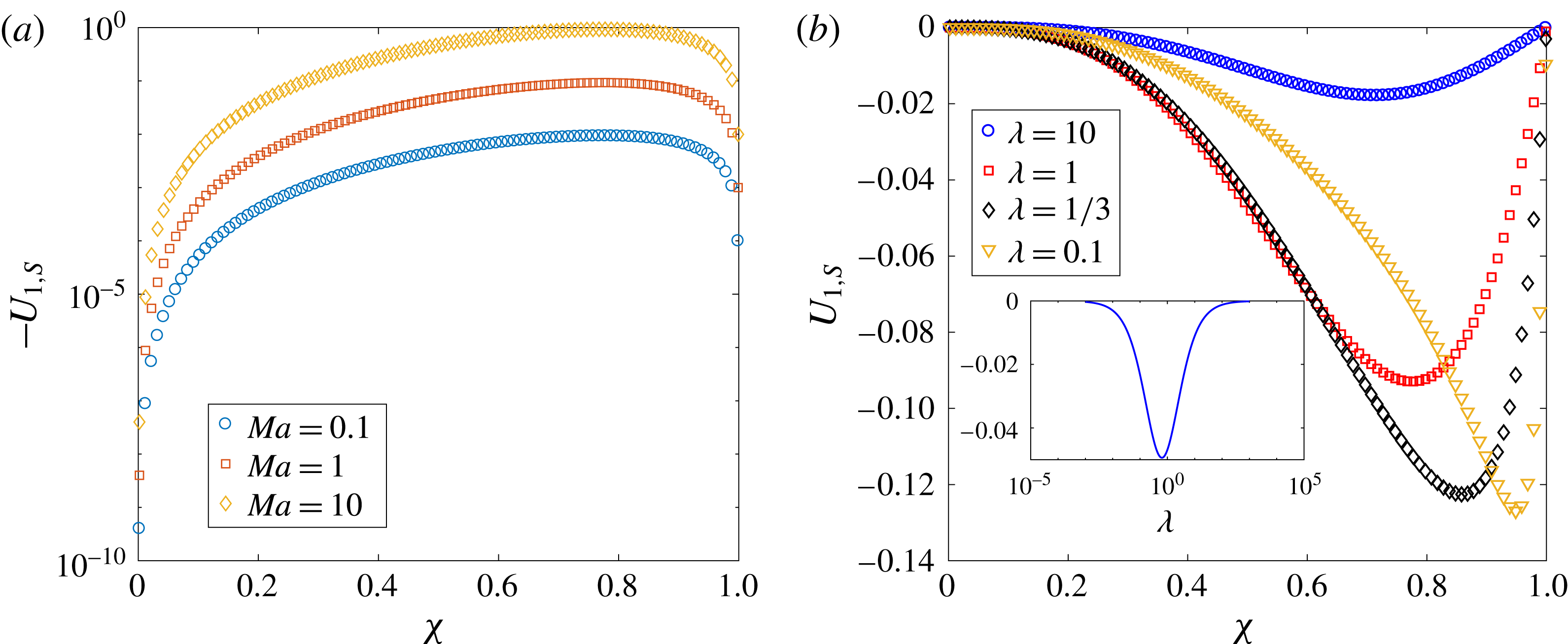
Figure 4. The variation of a two-mode squirmer velocity at
![]() $O(Pe_{s})$
,
$O(Pe_{s})$
,
![]() $U_{1,S}$
, with the size ratio
$U_{1,S}$
, with the size ratio
![]() $\unicode[STIX]{x1D712}$
for several values of (a)
$\unicode[STIX]{x1D712}$
for several values of (a)
![]() $Ma$
with
$Ma$
with
![]() $\unicode[STIX]{x1D706}=1$
and (b)
$\unicode[STIX]{x1D706}=1$
and (b)
![]() $\unicode[STIX]{x1D706}$
with
$\unicode[STIX]{x1D706}$
with
![]() $Ma=1$
. The inset in (b) shows the non-monotonic variation of
$Ma=1$
. The inset in (b) shows the non-monotonic variation of
![]() $U_{1,S}$
with the viscosity ratio
$U_{1,S}$
with the viscosity ratio
![]() $\unicode[STIX]{x1D706}$
for
$\unicode[STIX]{x1D706}$
for
![]() $\unicode[STIX]{x1D712}=0.5$
. All of the velocities are non-dimensionalized using
$\unicode[STIX]{x1D712}=0.5$
. All of the velocities are non-dimensionalized using
![]() $U_{sq}=2B_{1}/3$
.
$U_{sq}=2B_{1}/3$
.
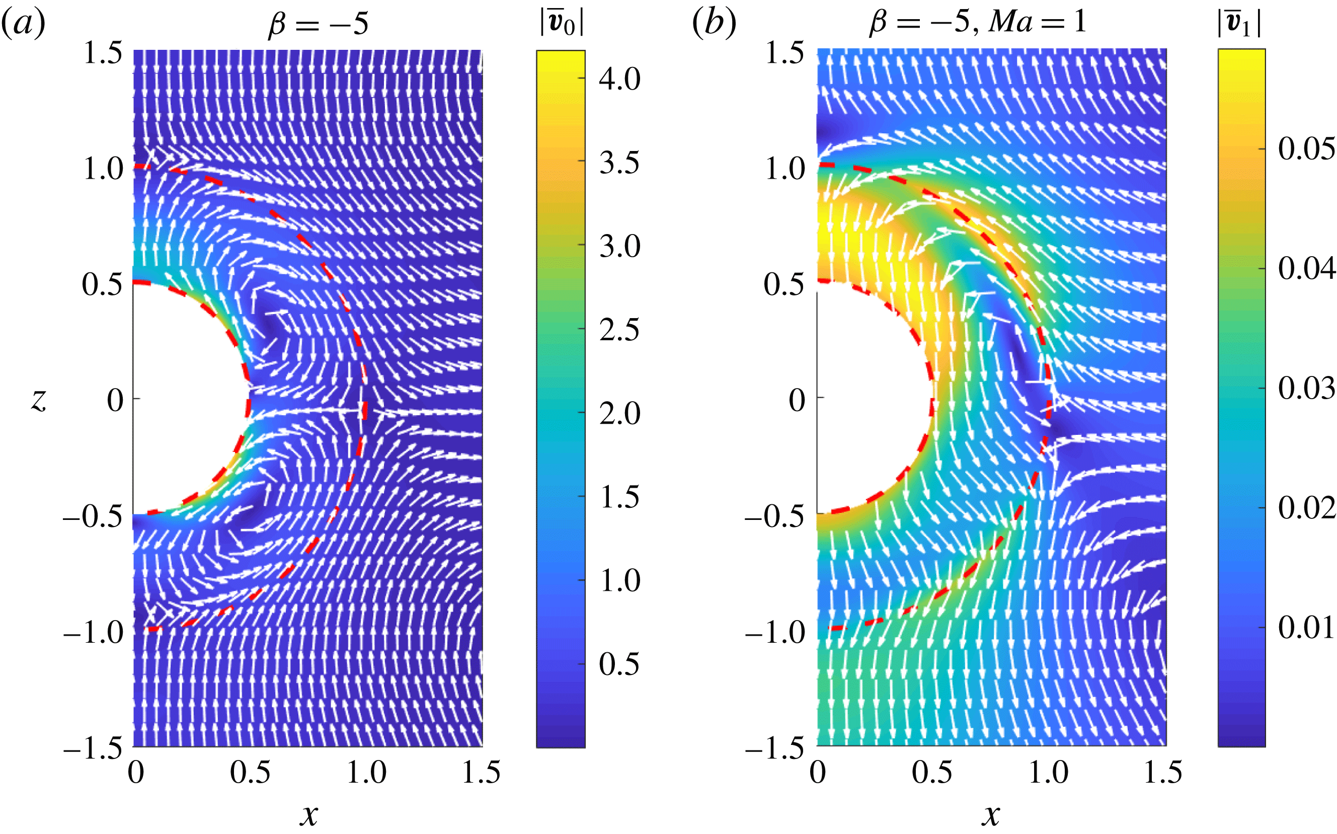
Figure 5. The (a)
![]() $O(1)$
and (b)
$O(1)$
and (b)
![]() $O(Pe_{s})$
flow fields outside a surfactant-laden drop containing a pusher swimmer at its centre in the laboratory frame of reference. The background colour and the unit vectors denote the magnitude and the direction of the velocity. The red dashed lines denote the surfaces of the swimmer and the drop. Here,
$O(Pe_{s})$
flow fields outside a surfactant-laden drop containing a pusher swimmer at its centre in the laboratory frame of reference. The background colour and the unit vectors denote the magnitude and the direction of the velocity. The red dashed lines denote the surfaces of the swimmer and the drop. Here,
![]() $\unicode[STIX]{x1D6FD}=B_{2}/B_{1}=-5$
,
$\unicode[STIX]{x1D6FD}=B_{2}/B_{1}=-5$
,
![]() $Ma=1$
,
$Ma=1$
,
![]() $\unicode[STIX]{x1D712}=0.5$
and
$\unicode[STIX]{x1D712}=0.5$
and
![]() $\unicode[STIX]{x1D706}=1$
. All of the velocities are non-dimensionalized using
$\unicode[STIX]{x1D706}=1$
. All of the velocities are non-dimensionalized using
![]() $U_{sq}=2B_{1}/3$
.
$U_{sq}=2B_{1}/3$
.
4.1.2 Far-field representation
In this section, we analyse how the advection of the surfactant modifies the far-field representation of the flow field due to a drop enclosing a swimmer at its centre. The far-field representation is useful in understanding the interaction of a particle (or a drop or swimming microorganism) with an interface or other particles. Even though the concentric configuration is unstable, simple expressions of the flow field associated with this configuration enable us to evaluate several quantities of interest.
In the laboratory frame, the radial component of the velocity far away from a two-mode swimmer in an unbounded fluid is given as (Blake Reference Blake1971)
where the overbar indicates that variables are written in the laboratory frame of reference. The radius of the drop is still used for non-dimensionalizing the length in the problem of a swimmer in an unbounded fluid, and this justifies the appearance of
![]() $\unicode[STIX]{x1D712}$
in (4.7). Similarly, the radial component of the velocity outside a drop enclosing a swimmer and far away from the drop is given as
$\unicode[STIX]{x1D712}$
in (4.7). Similarly, the radial component of the velocity outside a drop enclosing a swimmer and far away from the drop is given as
where
Using the expressions provided in appendix B, we derive the following two ratios:
 $$\begin{eqnarray}\displaystyle & \displaystyle \frac{\bar{v}_{0,r}^{(2)}|_{leading}}{\bar{u}_{r}|_{leading}}=-\frac{6\unicode[STIX]{x1D6EC}(\unicode[STIX]{x1D712}^{4}+3\unicode[STIX]{x1D712}^{3}+11/3\unicode[STIX]{x1D712}^{2}+3\unicode[STIX]{x1D712}+1)}{\left(\begin{array}{@{}l@{}}\displaystyle 4+(8\unicode[STIX]{x1D6EC}-4)\unicode[STIX]{x1D712}^{7}+(24\unicode[STIX]{x1D6EC}-12)\unicode[STIX]{x1D712}^{6}+(48\unicode[STIX]{x1D6EC}-24)\unicode[STIX]{x1D712}^{5}\\ \displaystyle +(45\unicode[STIX]{x1D6EC}-15)\unicode[STIX]{x1D712}^{4}+(15\unicode[STIX]{x1D6EC}+15)\unicode[STIX]{x1D712}^{3}+24\unicode[STIX]{x1D712}^{2}+12\unicode[STIX]{x1D712}\end{array}\right)}<0, & \displaystyle\end{eqnarray}$$
 $$\begin{eqnarray}\displaystyle & \displaystyle \frac{\bar{v}_{1,r}^{(2)}|_{leading}}{\bar{u}_{r}|_{leading}}=\frac{\left(\begin{array}{@{}l@{}}\displaystyle (24-24\unicode[STIX]{x1D712})(1-\unicode[STIX]{x1D6EC})\unicode[STIX]{x1D6EC}Ma(\unicode[STIX]{x1D712}^{4}+3\unicode[STIX]{x1D712}^{3}+11/3\unicode[STIX]{x1D712}^{2}+3\unicode[STIX]{x1D712}+1)\times \\ \displaystyle (\unicode[STIX]{x1D712}^{6}+4\unicode[STIX]{x1D712}^{5}+10\unicode[STIX]{x1D712}^{4}+55/4\unicode[STIX]{x1D712}^{3}+10\unicode[STIX]{x1D712}^{2}+4\unicode[STIX]{x1D712}+1)\end{array}\right)}{5\left(\begin{array}{@{}l@{}}\displaystyle 8\unicode[STIX]{x1D6EC}\unicode[STIX]{x1D712}^{7}+24\unicode[STIX]{x1D6EC}\unicode[STIX]{x1D712}^{6}-4\unicode[STIX]{x1D712}^{7}+48\unicode[STIX]{x1D6EC}\unicode[STIX]{x1D712}^{5}-12\unicode[STIX]{x1D712}^{6}+45\unicode[STIX]{x1D6EC}\unicode[STIX]{x1D712}^{4}\\ \displaystyle -24\unicode[STIX]{x1D712}^{5}+15\unicode[STIX]{x1D6EC}\unicode[STIX]{x1D712}^{3}-15\unicode[STIX]{x1D712}^{4}+15\unicode[STIX]{x1D712}^{3}+24\unicode[STIX]{x1D712}^{2}+12\unicode[STIX]{x1D712}+4\end{array}\right)^{2}}>0,\qquad & \displaystyle\end{eqnarray}$$
where
![]() $\unicode[STIX]{x1D6EC}=\unicode[STIX]{x1D706}/(\unicode[STIX]{x1D706}+1)$
. From (4.10), we deduce that the far-field representation of an
$\unicode[STIX]{x1D6EC}=\unicode[STIX]{x1D706}/(\unicode[STIX]{x1D706}+1)$
. From (4.10), we deduce that the far-field representation of an
![]() $O(1)$
flow field due to a pusher (puller) inside a drop is that of a puller (pusher) for all values of viscosity ratio and size ratio. Reigh et al. (Reference Reigh, Zhu, Gallaire and Lauga2017) derived a similar far-field representation of the flow field due to a clean drop encompassing a swimmer. On the other hand, the far-field representation of the
$O(1)$
flow field due to a pusher (puller) inside a drop is that of a puller (pusher) for all values of viscosity ratio and size ratio. Reigh et al. (Reference Reigh, Zhu, Gallaire and Lauga2017) derived a similar far-field representation of the flow field due to a clean drop encompassing a swimmer. On the other hand, the far-field representation of the
![]() $O(Pe_{s})$
flow field due to a pusher (puller) inside a drop is that of a pusher (puller): see (4.11). This far-field behaviour of a surfactant-covered drop containing a swimmer at its centre can be understood by plotting the
$O(Pe_{s})$
flow field due to a pusher (puller) inside a drop is that of a pusher (puller): see (4.11). This far-field behaviour of a surfactant-covered drop containing a swimmer at its centre can be understood by plotting the
![]() $O(1)$
and
$O(1)$
and
![]() $O(Pe_{s})$
flow fields in the laboratory frame of reference. We plot these flow fields for a pusher swimmer at the centre of a surfactant-laden drop for a viscosity ratio and a size ratio of 1 and 0.5 respectively in figure 5. A pusher swimmer in an unbounded fluid sucks fluid normal to its axis and ejects the fluid along its axis, while a puller swimmer draws fluid along its axis and ejects the fluid normal to its axis. As per the
$O(Pe_{s})$
flow fields in the laboratory frame of reference. We plot these flow fields for a pusher swimmer at the centre of a surfactant-laden drop for a viscosity ratio and a size ratio of 1 and 0.5 respectively in figure 5. A pusher swimmer in an unbounded fluid sucks fluid normal to its axis and ejects the fluid along its axis, while a puller swimmer draws fluid along its axis and ejects the fluid normal to its axis. As per the
![]() $O(1)$
flow field outside a drop, we see that a drop containing a pusher sucks fluid along its axis while ejecting normal to its axis, this flow field being the characteristic of a puller swimmer. Hence, the far-field representation of a clean drop containing a pusher swimmer at its centre is that of a puller swimmer. Similarly, based on the
$O(1)$
flow field outside a drop, we see that a drop containing a pusher sucks fluid along its axis while ejecting normal to its axis, this flow field being the characteristic of a puller swimmer. Hence, the far-field representation of a clean drop containing a pusher swimmer at its centre is that of a puller swimmer. Similarly, based on the
![]() $O(Pe_{s})$
flow field outside a drop, we see that a drop containing a pusher draws fluid normal to its axis while ejecting along its axis. As this flow is the characteristic of a pusher swimmer, it can be said that the far-field representation of the
$O(Pe_{s})$
flow field outside a drop, we see that a drop containing a pusher draws fluid normal to its axis while ejecting along its axis. As this flow is the characteristic of a pusher swimmer, it can be said that the far-field representation of the
![]() $O(Pe_{s})$
flow field due to a surfactant-laden drop containing a pusher swimmer at its centre is that of a pusher swimmer. Any deviation in the flow field outside the drop from this far-field behaviour is due to the contribution of the near-field flow. Since the
$O(Pe_{s})$
flow field due to a surfactant-laden drop containing a pusher swimmer at its centre is that of a pusher swimmer. Any deviation in the flow field outside the drop from this far-field behaviour is due to the contribution of the near-field flow. Since the
![]() $O(Pe_{s})$
flow field is an order of magnitude smaller than the
$O(Pe_{s})$
flow field is an order of magnitude smaller than the
![]() $O(1)$
flow field and is opposite to the
$O(1)$
flow field and is opposite to the
![]() $O(1)$
flow in the far field, we conclude that a surfactant-covered drop containing a pusher swimmer at its centre behaves as a puller; the strength of the far-field flow is reduced due to the surfactant redistribution.
$O(1)$
flow in the far field, we conclude that a surfactant-covered drop containing a pusher swimmer at its centre behaves as a puller; the strength of the far-field flow is reduced due to the surfactant redistribution.
4.1.3 Surfactant concentration
In this section, we will provide physical reasons for the decrease in the drop and swimmer velocities due to the surfactant redistribution when the swimmer is at the centre of the drop. For this purpose, we will utilize the justification provided to explain a similar decrease in the rise velocity of a drop (without any swimmer inside) due to the surfactant advection on its surface (Leal Reference Leal2007). The key idea is to analyse the surfactant concentration and the surface velocity of a drop containing a two-mode squirmer at its centre. The analytical expression for the surfactant concentration accurate to
![]() $O(Pe_{s})$
is given as
$O(Pe_{s})$
is given as
where
![]() $\unicode[STIX]{x1D6E4}_{0}=1$
and
$\unicode[STIX]{x1D6E4}_{0}=1$
and
![]() $\unicode[STIX]{x1D6E4}_{1}=\unicode[STIX]{x1D6E4}_{1,1}P_{1}(\cos \unicode[STIX]{x1D703})+\unicode[STIX]{x1D6E4}_{1,2}P_{2}(\cos \unicode[STIX]{x1D703})$
. Here,
$\unicode[STIX]{x1D6E4}_{1}=\unicode[STIX]{x1D6E4}_{1,1}P_{1}(\cos \unicode[STIX]{x1D703})+\unicode[STIX]{x1D6E4}_{1,2}P_{2}(\cos \unicode[STIX]{x1D703})$
. Here,
![]() $\unicode[STIX]{x1D6E4}_{1,1}$
and
$\unicode[STIX]{x1D6E4}_{1,1}$
and
![]() $\unicode[STIX]{x1D6E4}_{1,2}$
are given as
$\unicode[STIX]{x1D6E4}_{1,2}$
are given as
 $$\begin{eqnarray}\displaystyle & \displaystyle \unicode[STIX]{x1D6E4}_{1,2}=\frac{3}{2}\frac{6(\unicode[STIX]{x1D712}^{4}+3\unicode[STIX]{x1D712}^{3}+11/3\unicode[STIX]{x1D712}^{2}+3\unicode[STIX]{x1D712}+1)\unicode[STIX]{x1D6FD}\unicode[STIX]{x1D712}^{2}\unicode[STIX]{x1D706}}{\left(\begin{array}{@{}l@{}}\displaystyle (12\unicode[STIX]{x1D706}-12)\unicode[STIX]{x1D712}^{7}+(36\unicode[STIX]{x1D706}-36)\unicode[STIX]{x1D712}^{6}+(72\unicode[STIX]{x1D706}-72)\unicode[STIX]{x1D712}^{5}+(90\unicode[STIX]{x1D706}-45)\unicode[STIX]{x1D712}^{4}\\ \displaystyle +\,(90\unicode[STIX]{x1D706}+45)\unicode[STIX]{x1D712}^{3}+(72\unicode[STIX]{x1D706}+72)\unicode[STIX]{x1D712}^{2}+(36\unicode[STIX]{x1D706}+36)\unicode[STIX]{x1D712}+12\unicode[STIX]{x1D706}+12\end{array}\right)}.\qquad & \displaystyle\end{eqnarray}$$
Similarly, the expression for the surface velocity of the drop accurate to
![]() $O(Pe_{s})$
is given as
$O(Pe_{s})$
is given as
where
 $$\begin{eqnarray}\displaystyle v_{0,\unicode[STIX]{x1D703}}|_{r=1} & = & \displaystyle \frac{5\unicode[STIX]{x1D712}^{3}B_{1}\unicode[STIX]{x1D706}\sin (\unicode[STIX]{x1D703})}{2\unicode[STIX]{x1D712}^{5}\unicode[STIX]{x1D706}-2\unicode[STIX]{x1D712}^{5}+3\unicode[STIX]{x1D706}+2}\nonumber\\ \displaystyle & & \displaystyle -\,\frac{6\cos (\unicode[STIX]{x1D703})B_{2}\unicode[STIX]{x1D706}\sin (\unicode[STIX]{x1D703})\unicode[STIX]{x1D712}^{2}(\unicode[STIX]{x1D712}^{4}+3\unicode[STIX]{x1D712}^{3}+11/3\unicode[STIX]{x1D712}^{2}+3\unicode[STIX]{x1D712}+1)}{\left(\begin{array}{@{}l@{}}\displaystyle (4\unicode[STIX]{x1D706}-4)\unicode[STIX]{x1D712}^{7}+(12\unicode[STIX]{x1D706}-12)\unicode[STIX]{x1D712}^{6}+(24\unicode[STIX]{x1D706}-24)\unicode[STIX]{x1D712}^{5}+(30\unicode[STIX]{x1D706}-15)\unicode[STIX]{x1D712}^{4}\\ \displaystyle +\,(30\unicode[STIX]{x1D706}+15)\unicode[STIX]{x1D712}^{3}+(24\unicode[STIX]{x1D706}+24)\unicode[STIX]{x1D712}^{2}+(12\unicode[STIX]{x1D706}+12)\unicode[STIX]{x1D712}+4\unicode[STIX]{x1D706}+4\end{array}\right)},\qquad \quad\end{eqnarray}$$
 $$\begin{eqnarray}\displaystyle v_{1,\unicode[STIX]{x1D703}}|_{r=1} & = & \displaystyle \frac{5Ma\unicode[STIX]{x1D712}^{3}\unicode[STIX]{x1D706}B_{1}(\unicode[STIX]{x1D712}^{5}-1)\sin (\unicode[STIX]{x1D703})}{(2\unicode[STIX]{x1D712}^{5}\unicode[STIX]{x1D706}-2\unicode[STIX]{x1D712}^{5}+3\unicode[STIX]{x1D706}+2)^{2}}\nonumber\\ \displaystyle & & \displaystyle -\,\frac{3}{10}\frac{\left(\begin{array}{@{}l@{}}\displaystyle (\unicode[STIX]{x1D712}-1)\cos (\unicode[STIX]{x1D703})\unicode[STIX]{x1D712}^{2}\unicode[STIX]{x1D706}(\unicode[STIX]{x1D712}^{4}+3\unicode[STIX]{x1D712}^{3}+11/3\unicode[STIX]{x1D712}^{2}+3\unicode[STIX]{x1D712}+1)\sin (\unicode[STIX]{x1D703})\\ \displaystyle \times \,MaB_{2}\left(\unicode[STIX]{x1D712}^{6}+4\unicode[STIX]{x1D712}^{5}+10\unicode[STIX]{x1D712}^{4}+\frac{55\unicode[STIX]{x1D712}^{3}}{4}+10\unicode[STIX]{x1D712}^{2}+4\unicode[STIX]{x1D712}+1\right)\end{array}\right)}{\left(\begin{array}{@{}l@{}}\displaystyle (\unicode[STIX]{x1D706}-1)\unicode[STIX]{x1D712}^{7}+(3\unicode[STIX]{x1D706}-3)\unicode[STIX]{x1D712}^{6}+(6\unicode[STIX]{x1D706}-6)\unicode[STIX]{x1D712}^{5}+(15/2\unicode[STIX]{x1D706}-{\textstyle \frac{15}{4}})\unicode[STIX]{x1D712}^{4}\\ \displaystyle +\,(15/2\unicode[STIX]{x1D706}+{\textstyle \frac{15}{4}})\unicode[STIX]{x1D712}^{3}+(6\unicode[STIX]{x1D706}+6)\unicode[STIX]{x1D712}^{2}+(3\unicode[STIX]{x1D706}+3)\unicode[STIX]{x1D712}+\unicode[STIX]{x1D706}+1\end{array}\right)}.\qquad\end{eqnarray}$$
For a clean interface, the swimmer velocity, the drop velocity and the drop surface velocity decrease as the viscosity ratio
![]() $\unicode[STIX]{x1D706}$
decreases (see figures 3
a,b and 6). A similar decrease in the velocity of a swimming microorganism, modelled as a Stokes dipole, near a plane clean interface has already been reported (Lopez & Lauga Reference Lopez and Lauga2014); the reason is the decrease in the strength of the image flow field with a decrease in
$\unicode[STIX]{x1D706}$
decreases (see figures 3
a,b and 6). A similar decrease in the velocity of a swimming microorganism, modelled as a Stokes dipole, near a plane clean interface has already been reported (Lopez & Lauga Reference Lopez and Lauga2014); the reason is the decrease in the strength of the image flow field with a decrease in
![]() $\unicode[STIX]{x1D706}$
. Now, for a swimmer inside a clean drop, we attribute the decrease in the swimmer velocity, drop velocity and drop surface velocity to a corresponding decrease in the strength of the image flow field with a decrease in
$\unicode[STIX]{x1D706}$
. Now, for a swimmer inside a clean drop, we attribute the decrease in the swimmer velocity, drop velocity and drop surface velocity to a corresponding decrease in the strength of the image flow field with a decrease in
![]() $\unicode[STIX]{x1D706}$
.
$\unicode[STIX]{x1D706}$
.
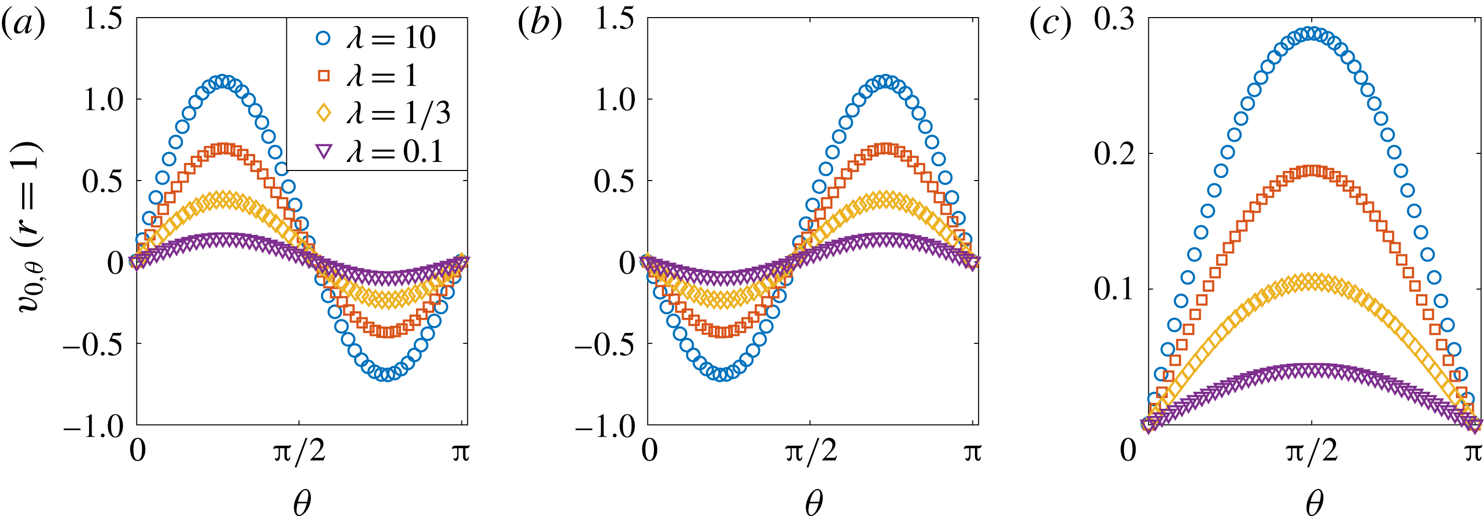
Figure 6. The surface velocity of a clean drop containing (a) a pusher
![]() $(\unicode[STIX]{x1D6FD}=-5)$
, (b) a puller
$(\unicode[STIX]{x1D6FD}=-5)$
, (b) a puller
![]() $(\unicode[STIX]{x1D6FD}=5)$
and (c) a neutral swimmer
$(\unicode[STIX]{x1D6FD}=5)$
and (c) a neutral swimmer
![]() $(\unicode[STIX]{x1D6FD}=0)$
at its centre, plotted as a function of the polar angle for various viscosity ratios. Here, the size ratio
$(\unicode[STIX]{x1D6FD}=0)$
at its centre, plotted as a function of the polar angle for various viscosity ratios. Here, the size ratio
![]() $\unicode[STIX]{x1D712}$
is taken as 0.5. All of the velocities are non-dimensionalized using
$\unicode[STIX]{x1D712}$
is taken as 0.5. All of the velocities are non-dimensionalized using
![]() $U_{sq}=2B_{1}/3$
.
$U_{sq}=2B_{1}/3$
.
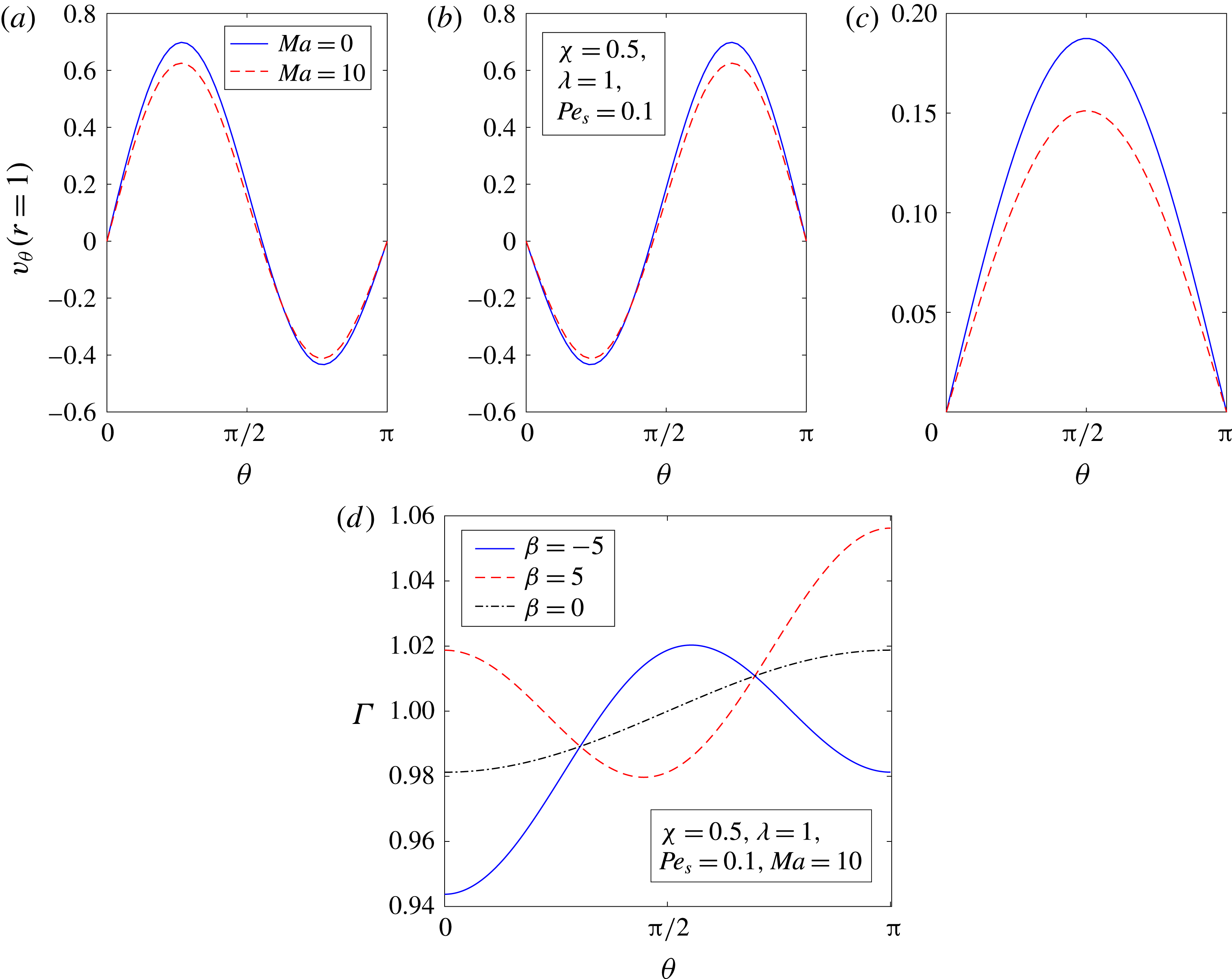
Figure 7. The variation of the surface velocity of the drop with the polar angle for (a) a pusher
![]() $(\unicode[STIX]{x1D6FD}=-5)$
, (b) a puller
$(\unicode[STIX]{x1D6FD}=-5)$
, (b) a puller
![]() $(\unicode[STIX]{x1D6FD}=5)$
and (c) a neutral swimmer
$(\unicode[STIX]{x1D6FD}=5)$
and (c) a neutral swimmer
![]() $(\unicode[STIX]{x1D6FD}=0)$
at the centre of a drop. The solid lines indicate the results obtained for a clean drop, while the dashed lines denote the results for a surfactant-laden drop with
$(\unicode[STIX]{x1D6FD}=0)$
at the centre of a drop. The solid lines indicate the results obtained for a clean drop, while the dashed lines denote the results for a surfactant-laden drop with
![]() $Ma=10$
and
$Ma=10$
and
![]() $Pe_{s}=0.1$
. (d) The variation of the surfactant concentration with the polar angle. Here, the solid, dashed and dash-dotted lines denote the results obtained for a pusher, a puller and a neutral swimmer inside the drop respectively. The size ratio,
$Pe_{s}=0.1$
. (d) The variation of the surfactant concentration with the polar angle. Here, the solid, dashed and dash-dotted lines denote the results obtained for a pusher, a puller and a neutral swimmer inside the drop respectively. The size ratio,
![]() $\unicode[STIX]{x1D712}$
, and the viscosity ratio,
$\unicode[STIX]{x1D712}$
, and the viscosity ratio,
![]() $\unicode[STIX]{x1D706}$
, are taken as 0.5 and 1 respectively. All of the velocities are non-dimensionalized using
$\unicode[STIX]{x1D706}$
, are taken as 0.5 and 1 respectively. All of the velocities are non-dimensionalized using
![]() $U_{sq}=2B_{1}/3$
.
$U_{sq}=2B_{1}/3$
.
We plot in figure 7 the variation of the surface velocity of the drop and the surfactant concentration with the polar angle
![]() $(\unicode[STIX]{x1D703})$
for various values of the Marangoni number,
$(\unicode[STIX]{x1D703})$
for various values of the Marangoni number,
![]() $Ma$
, and
$Ma$
, and
![]() $\unicode[STIX]{x1D6FD}$
. We note that
$\unicode[STIX]{x1D6FD}$
. We note that
![]() $v_{\unicode[STIX]{x1D703}}$
should be zero at the front and the back of the drop due to the axisymmetric condition. Analysing the results for a neutral swimmer
$v_{\unicode[STIX]{x1D703}}$
should be zero at the front and the back of the drop due to the axisymmetric condition. Analysing the results for a neutral swimmer
![]() $(\unicode[STIX]{x1D6FD}=0)$
, we see that the surface velocity at
$(\unicode[STIX]{x1D6FD}=0)$
, we see that the surface velocity at
![]() $O(1)$
is always positive, which leads to a monotonically increasing surfactant concentration, as shown in figure 7(d). This give rise to a maximum (minimum) interfacial tension at the front (back) of the drop. This inhomogeneous interfacial tension generates a tensile stress imbalance which pulls the drop surface elements from the back to the front, thereby reducing the drop surface velocity. The fluid in the vicinity of the drop also gets pulled from the back to the front of the drop and since this direction of pull is opposite to the free-stream velocity, the drop velocity reduces due to the surfactant redistribution. Similarly, for a pusher inside a drop, since the drop surface velocity (at
$O(1)$
is always positive, which leads to a monotonically increasing surfactant concentration, as shown in figure 7(d). This give rise to a maximum (minimum) interfacial tension at the front (back) of the drop. This inhomogeneous interfacial tension generates a tensile stress imbalance which pulls the drop surface elements from the back to the front, thereby reducing the drop surface velocity. The fluid in the vicinity of the drop also gets pulled from the back to the front of the drop and since this direction of pull is opposite to the free-stream velocity, the drop velocity reduces due to the surfactant redistribution. Similarly, for a pusher inside a drop, since the drop surface velocity (at
![]() $O(1)$
) is positive near the front and negative near the back, it brings the surfactant from both the front and back to the centre of the drop, as shown in figure 7(d). This gives rise to a minimum (maximum) interfacial tension at the centre (the front and the back) of the drop. Again, such inhomogeneous interfacial tension pulls the drop surface elements from the centre towards the front (the back) in the upper (lower) half of the drop, thereby reducing the drop surface velocity. This Marangoni induced drop surface flow pulls the fluid nearby in the same direction. Since this induced flow near the upper (lower) half of the drop is opposite to (along) the free-stream flow and the flow near the upper half is dominant due to
$O(1)$
) is positive near the front and negative near the back, it brings the surfactant from both the front and back to the centre of the drop, as shown in figure 7(d). This gives rise to a minimum (maximum) interfacial tension at the centre (the front and the back) of the drop. Again, such inhomogeneous interfacial tension pulls the drop surface elements from the centre towards the front (the back) in the upper (lower) half of the drop, thereby reducing the drop surface velocity. This Marangoni induced drop surface flow pulls the fluid nearby in the same direction. Since this induced flow near the upper (lower) half of the drop is opposite to (along) the free-stream flow and the flow near the upper half is dominant due to
![]() $\unicode[STIX]{x1D6FE}|_{top}-\unicode[STIX]{x1D6FE}|_{centre}>\unicode[STIX]{x1D6FE}|_{bottom}-\unicode[STIX]{x1D6FE}|_{centre}$
, we expect the drop velocity to be reduced due to the surfactant redistribution. One can use a similar reasoning to understand the Marangoni induced decrease in the drop velocity and drop surface velocity for a puller swimmer at the centre of a drop. In conclusion, for any two-mode swimmer at the centre of the drop, the surfactant redistribution on the drop surface reduces the drop velocity and the drop surface velocity. We recall that the drop surface velocity also decreases due to a decrease in
$\unicode[STIX]{x1D6FE}|_{top}-\unicode[STIX]{x1D6FE}|_{centre}>\unicode[STIX]{x1D6FE}|_{bottom}-\unicode[STIX]{x1D6FE}|_{centre}$
, we expect the drop velocity to be reduced due to the surfactant redistribution. One can use a similar reasoning to understand the Marangoni induced decrease in the drop velocity and drop surface velocity for a puller swimmer at the centre of a drop. In conclusion, for any two-mode swimmer at the centre of the drop, the surfactant redistribution on the drop surface reduces the drop velocity and the drop surface velocity. We recall that the drop surface velocity also decreases due to a decrease in
![]() $\unicode[STIX]{x1D706}$
for a clean drop containing a swimmer at its centre. Therefore, for a swimmer at the centre of the drop, one can understand the influence of surfactant redistribution on the swimmer or drop velocity by assuming that the surfactant advection solely decreases the apparent viscosity ratio (apparent because the actual viscosity ratio is not affected by the surfactant redistribution). Since the swimmer and drop velocities reduce due to a decrease in
$\unicode[STIX]{x1D706}$
for a clean drop containing a swimmer at its centre. Therefore, for a swimmer at the centre of the drop, one can understand the influence of surfactant redistribution on the swimmer or drop velocity by assuming that the surfactant advection solely decreases the apparent viscosity ratio (apparent because the actual viscosity ratio is not affected by the surfactant redistribution). Since the swimmer and drop velocities reduce due to a decrease in
![]() $\unicode[STIX]{x1D706}$
for a clean drop containing a swimmer at its centre, we expect a similar decrease in the swimmer and drop velocities due to the advection of the surfactant on the drop surface.
$\unicode[STIX]{x1D706}$
for a clean drop containing a swimmer at its centre, we expect a similar decrease in the swimmer and drop velocities due to the advection of the surfactant on the drop surface.
4.1.4 Co-swimming
As mentioned earlier, a two-mode swimmer located at the centre of the drop always has a velocity larger than that of the drop, thereby making the concentric configuration unsteady. Due to the recent advancements in artificial microswimmers, one can make a swimmer such that it transports the drop by lying at the centre of the drop for all times. Since the swimmer and drop velocities accurate to
![]() $O(Pe_{s})$
depend only on
$O(Pe_{s})$
depend only on
![]() $A_{1}$
and
$A_{1}$
and
![]() $B_{1}$
modes, we can choose the
$B_{1}$
modes, we can choose the
![]() $A_{1}$
mode such that
$A_{1}$
mode such that
![]() $U_{S}=U_{D}$
. Using (4.3)–(4.6), we derive the dimensionless
$U_{S}=U_{D}$
. Using (4.3)–(4.6), we derive the dimensionless
![]() $A_{1}$
mode as
$A_{1}$
mode as
 $$\begin{eqnarray}\displaystyle \unicode[STIX]{x1D6FC}_{co}=\frac{A_{1}}{B_{1}}=\frac{\left(\begin{array}{@{}l@{}}\displaystyle -12(\unicode[STIX]{x1D712}-1)((\unicode[STIX]{x1D706}-1)\unicode[STIX]{x1D712}^{4}+(\unicode[STIX]{x1D706}-1)\unicode[STIX]{x1D712}^{3}+(\unicode[STIX]{x1D706}+{\textstyle \frac{2}{3}})\unicode[STIX]{x1D712}^{2}+(\unicode[STIX]{x1D706}+{\textstyle \frac{2}{3}})\unicode[STIX]{x1D712}+\unicode[STIX]{x1D706}+{\textstyle \frac{2}{3}})\\ \displaystyle \times ((\unicode[STIX]{x1D706}-1)\unicode[STIX]{x1D712}^{5}+{\textstyle \frac{3}{2}}\unicode[STIX]{x1D706}+1)-5MaPe_{s}\unicode[STIX]{x1D712}^{3}\unicode[STIX]{x1D706}(2\unicode[STIX]{x1D712}^{5}-5\unicode[STIX]{x1D712}^{2}+3)\end{array}\right)}{\left(\begin{array}{@{}l@{}}\displaystyle (2\unicode[STIX]{x1D712}^{5}\unicode[STIX]{x1D706}-2\unicode[STIX]{x1D712}^{5}+3\unicode[STIX]{x1D706}+2)(12\unicode[STIX]{x1D712}^{5}\unicode[STIX]{x1D706}-12\unicode[STIX]{x1D712}^{5}+10\unicode[STIX]{x1D712}^{3}+3\unicode[STIX]{x1D706}+2)\\ \displaystyle +\,5MaPe_{s}\unicode[STIX]{x1D712}^{3}\unicode[STIX]{x1D706}(2\unicode[STIX]{x1D712}^{5}-5\unicode[STIX]{x1D712}^{2}+3)\end{array}\right)}. & & \displaystyle \nonumber\\ \displaystyle & & \displaystyle\end{eqnarray}$$
We plot the variation of the co-swimming speed,
![]() $U_{SD}$
, with the viscosity ratio, size ratio and
$U_{SD}$
, with the viscosity ratio, size ratio and
![]() $Ma$
in figure 8. We note that the results of this section are valid for any general squirmer inside a drop except that
$Ma$
in figure 8. We note that the results of this section are valid for any general squirmer inside a drop except that
![]() $A_{1}$
is chosen according to (4.18). Analysis of a two-mode squirmer at the centre of the drop revealed that the swimmer and drop velocities approach unity when the size of the swimmer approaches the size of the drop, i.e.
$A_{1}$
is chosen according to (4.18). Analysis of a two-mode squirmer at the centre of the drop revealed that the swimmer and drop velocities approach unity when the size of the swimmer approaches the size of the drop, i.e.
![]() $\unicode[STIX]{x1D712}\rightarrow 1$
. For this reason, as
$\unicode[STIX]{x1D712}\rightarrow 1$
. For this reason, as
![]() $\unicode[STIX]{x1D712}\rightarrow 1$
,
$\unicode[STIX]{x1D712}\rightarrow 1$
,
![]() $\unicode[STIX]{x1D6FC}_{co}$
should approach zero while the co-swimming speed should approach unity for all values of the viscosity ratio and
$\unicode[STIX]{x1D6FC}_{co}$
should approach zero while the co-swimming speed should approach unity for all values of the viscosity ratio and
![]() $Ma$
, as shown in figure 8. Furthermore, for large values of the drop viscosities (for instance, for
$Ma$
, as shown in figure 8. Furthermore, for large values of the drop viscosities (for instance, for
![]() $\unicode[STIX]{x1D706}=10$
), the co-swimming microswimmer and drop have speeds larger than the speed of the swimmer in an unbounded fluid. Similarly to the results for a two-mode swimmer inside a drop, we see that the advection of surfactant also reduces the co-swimming speed, as shown in figure 8.
$\unicode[STIX]{x1D706}=10$
), the co-swimming microswimmer and drop have speeds larger than the speed of the swimmer in an unbounded fluid. Similarly to the results for a two-mode swimmer inside a drop, we see that the advection of surfactant also reduces the co-swimming speed, as shown in figure 8.
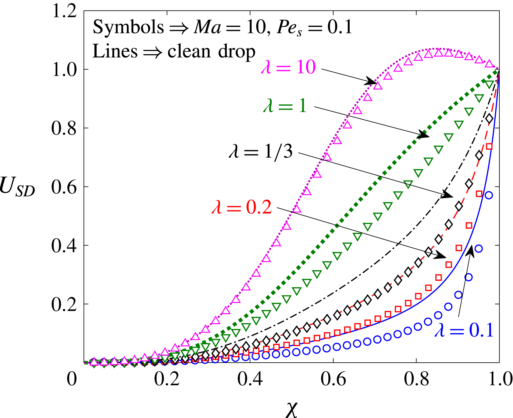
Figure 8. The variation of the co-swimming speed,
![]() $U_{SD}$
, with the size ratio for various values of the viscosity ratio and the Marangoni number. The lines indicate the results obtained for a clean drop, while the symbols denote the results obtained for a surfactant-laden drop with
$U_{SD}$
, with the size ratio for various values of the viscosity ratio and the Marangoni number. The lines indicate the results obtained for a clean drop, while the symbols denote the results obtained for a surfactant-laden drop with
![]() $Ma=10$
and
$Ma=10$
and
![]() $Pe_{s}=0.1$
. Here,
$Pe_{s}=0.1$
. Here,
![]() $U_{sq}=2B_{1}/3$
is used to non-dimensionalize the co-swimming speed.
$U_{sq}=2B_{1}/3$
is used to non-dimensionalize the co-swimming speed.
4.2 Eccentric configurations
In this section, we study the variation of the swimmer and drop velocities with the eccentricity. Using this analysis, we answer the following questions. Does a two-mode squirmer inside a clean drop achieve a configuration where it will swim with the drop
![]() $(U_{S}=U_{D})$
? If such a configuration exists and is stable, what is the effect of the advection of the surfactant on this configuration? How does the surfactant redistribution affect the swimmer and drop velocities for eccentric configurations? Prior to the analysis, we validate the velocities of the swimmer and drop for small eccentricities (obtained using the bipolar coordinate method) with the velocities for a concentric configuration (obtained using Lamb’s general solution), and these results are plotted in figures 14 and 15 in appendix F.
$(U_{S}=U_{D})$
? If such a configuration exists and is stable, what is the effect of the advection of the surfactant on this configuration? How does the surfactant redistribution affect the swimmer and drop velocities for eccentric configurations? Prior to the analysis, we validate the velocities of the swimmer and drop for small eccentricities (obtained using the bipolar coordinate method) with the velocities for a concentric configuration (obtained using Lamb’s general solution), and these results are plotted in figures 14 and 15 in appendix F.
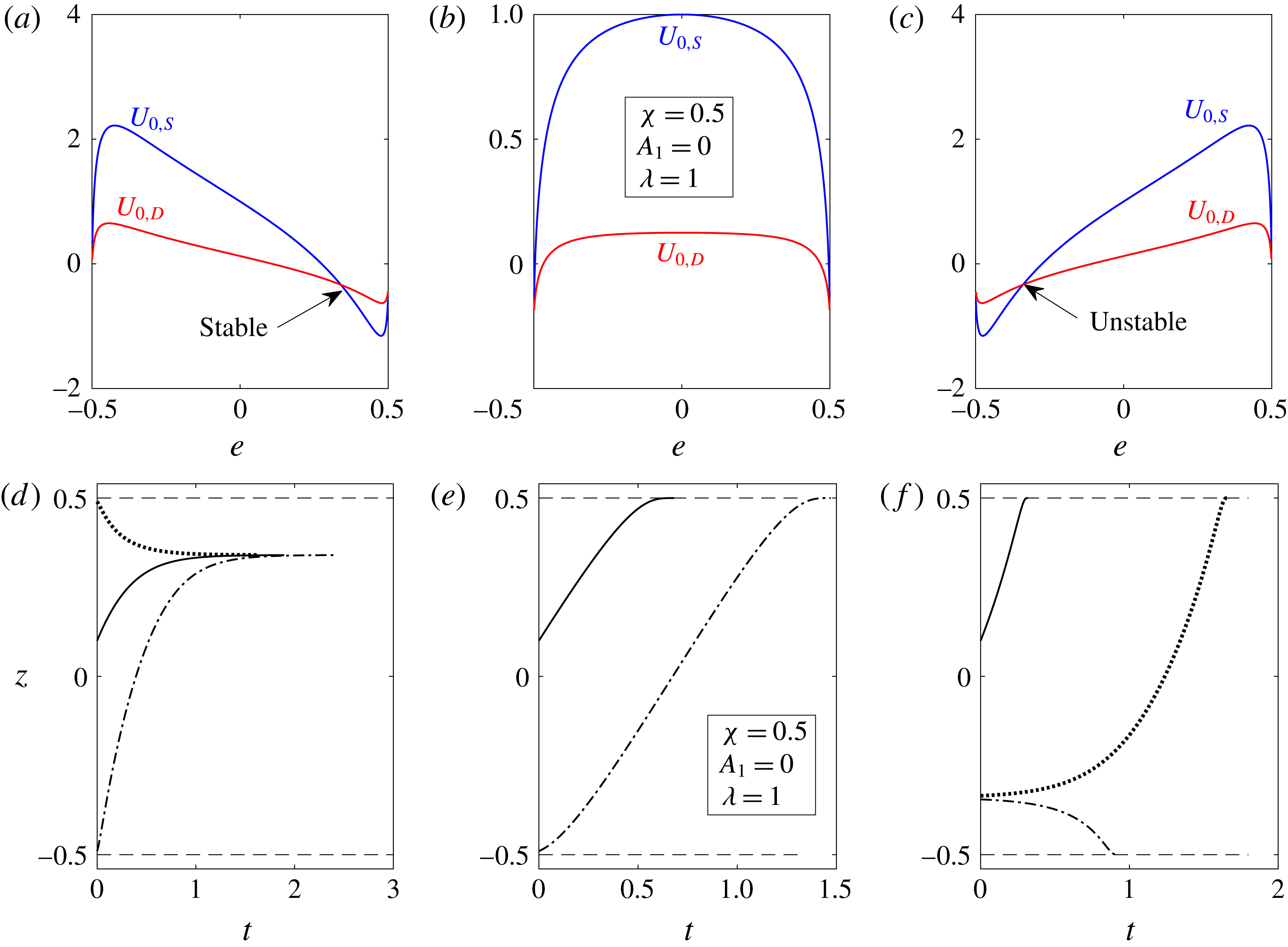
Figure 9. For a two-mode swimmer inside a clean drop, the velocities of the swimmer
![]() $(U_{0,S})$
(blue lines) and the drop
$(U_{0,S})$
(blue lines) and the drop
![]() $(U_{0,D})$
(red lines) are plotted as a function of the eccentricity
$(U_{0,D})$
(red lines) are plotted as a function of the eccentricity
![]() $(e)$
in (a–c). The time evolution of the centre of the swimmer when released from different positions inside a clean drop is plotted in (d–f). Panels (a,d) denote the results for a pusher
$(e)$
in (a–c). The time evolution of the centre of the swimmer when released from different positions inside a clean drop is plotted in (d–f). Panels (a,d) denote the results for a pusher
![]() $(\unicode[STIX]{x1D6FD}=-5)$
, while (b,e) denote those for a neutral swimmer
$(\unicode[STIX]{x1D6FD}=-5)$
, while (b,e) denote those for a neutral swimmer
![]() $(\unicode[STIX]{x1D6FD}=0)$
and (c,f) denote those for a puller
$(\unicode[STIX]{x1D6FD}=0)$
and (c,f) denote those for a puller
![]() $(\unicode[STIX]{x1D6FD}=5)$
. Here,
$(\unicode[STIX]{x1D6FD}=5)$
. Here,
![]() $e>0~(e<0)$
indicates that the centre of the swimmer is above (below) the centre of the drop. The size ratio,
$e>0~(e<0)$
indicates that the centre of the swimmer is above (below) the centre of the drop. The size ratio,
![]() $\unicode[STIX]{x1D712}$
, and the viscosity ratio,
$\unicode[STIX]{x1D712}$
, and the viscosity ratio,
![]() $\unicode[STIX]{x1D706}$
, are taken as 0.5 and 1 respectively. All of the velocities are non-dimensionalized using
$\unicode[STIX]{x1D706}$
, are taken as 0.5 and 1 respectively. All of the velocities are non-dimensionalized using
![]() $U_{sq}=2B_{1}/3$
. The dashed lines indicate the positions at which the swimmer touches the drop.
$U_{sq}=2B_{1}/3$
. The dashed lines indicate the positions at which the swimmer touches the drop.
In figure 9(a–c), we plot the swimmer and drop velocities at
![]() $O(1)$
(this corresponds to the swimmer inside a clean drop) as a function of the eccentricity. Since the dependence of these velocities on the eccentricity is qualitatively the same for various values of the size ratio
$O(1)$
(this corresponds to the swimmer inside a clean drop) as a function of the eccentricity. Since the dependence of these velocities on the eccentricity is qualitatively the same for various values of the size ratio
![]() $(\unicode[STIX]{x1D712})$
and the viscosity ratio
$(\unicode[STIX]{x1D712})$
and the viscosity ratio
![]() $(\unicode[STIX]{x1D706})$
, we report these plots for single representative values of
$(\unicode[STIX]{x1D706})$
, we report these plots for single representative values of
![]() $\unicode[STIX]{x1D712}$
and
$\unicode[STIX]{x1D712}$
and
![]() $\unicode[STIX]{x1D706}$
, namely
$\unicode[STIX]{x1D706}$
, namely
![]() $\unicode[STIX]{x1D712}=0.5$
and
$\unicode[STIX]{x1D712}=0.5$
and
![]() $\unicode[STIX]{x1D706}=1$
. In figure 9(d–f), we plot the time evolution of the position of the swimmer for various initial positions of the swimmer inside a drop. Here, panels (a,d), (b,e) and (c,f) present the results for a pusher
$\unicode[STIX]{x1D706}=1$
. In figure 9(d–f), we plot the time evolution of the position of the swimmer for various initial positions of the swimmer inside a drop. Here, panels (a,d), (b,e) and (c,f) present the results for a pusher
![]() $(\unicode[STIX]{x1D6FD}=-5)$
, a neutral swimmer
$(\unicode[STIX]{x1D6FD}=-5)$
, a neutral swimmer
![]() $(\unicode[STIX]{x1D6FD}=0)$
and a puller
$(\unicode[STIX]{x1D6FD}=0)$
and a puller
![]() $(\unicode[STIX]{x1D6FD}=5)$
inside a drop respectively. From figure 9(b), we observe that a neutral swimmer inside a drop has a velocity larger than that of the drop for all values of the eccentricity. Hence, a neutral swimmer inside a clean drop moves towards the front of the drop, as shown by the time evolution of its position in figure 9(e). From figure 9(c), we see that a puller inside a clean drop has a fixed point (at which
$(\unicode[STIX]{x1D6FD}=5)$
inside a drop respectively. From figure 9(b), we observe that a neutral swimmer inside a drop has a velocity larger than that of the drop for all values of the eccentricity. Hence, a neutral swimmer inside a clean drop moves towards the front of the drop, as shown by the time evolution of its position in figure 9(e). From figure 9(c), we see that a puller inside a clean drop has a fixed point (at which
![]() $e<0$
), in the sense that the swimmer and drop velocities are the same at this fixed point. However, this fixed point is globally unstable. This is because a swimmer located above (below) the fixed point has a positive (negative) velocity with respect to the drop, because of which it moves away from the fixed point, towards the top (bottom) surface of the drop, as shown by the time evolution of its position in figure 9(f). Finally, from figure 9(a), we notice that a pusher inside a clean drop has a globally stable fixed point (at which
$e<0$
), in the sense that the swimmer and drop velocities are the same at this fixed point. However, this fixed point is globally unstable. This is because a swimmer located above (below) the fixed point has a positive (negative) velocity with respect to the drop, because of which it moves away from the fixed point, towards the top (bottom) surface of the drop, as shown by the time evolution of its position in figure 9(f). Finally, from figure 9(a), we notice that a pusher inside a clean drop has a globally stable fixed point (at which
![]() $e>0$
). This is because a swimmer located above (below) the fixed point has a negative (positive) velocity with respect to the drop, due to which it moves towards the fixed point, as shown by the time evolution of its position in figure 9(d). To generalize these observations, we note that for a two-mode swimmer inside a clean drop, there exists a value
$e>0$
). This is because a swimmer located above (below) the fixed point has a negative (positive) velocity with respect to the drop, due to which it moves towards the fixed point, as shown by the time evolution of its position in figure 9(d). To generalize these observations, we note that for a two-mode swimmer inside a clean drop, there exists a value
![]() $\unicode[STIX]{x1D6FD}=\unicode[STIX]{x1D6FD}_{c}$
, where
$\unicode[STIX]{x1D6FD}=\unicode[STIX]{x1D6FD}_{c}$
, where
![]() $\unicode[STIX]{x1D6FD}_{c}<0$
is a function of the viscosity ratio and the size ratio, such that a swimmer with
$\unicode[STIX]{x1D6FD}_{c}<0$
is a function of the viscosity ratio and the size ratio, such that a swimmer with
![]() $|\unicode[STIX]{x1D6FD}|<-\unicode[STIX]{x1D6FD}_{c}$
behaves as a neutral swimmer. Such a swimmer does not have any fixed points inside the drop and since it is faster than the drop, it moves to the top surface of the drop. On the other hand, a two-mode swimmer with
$|\unicode[STIX]{x1D6FD}|<-\unicode[STIX]{x1D6FD}_{c}$
behaves as a neutral swimmer. Such a swimmer does not have any fixed points inside the drop and since it is faster than the drop, it moves to the top surface of the drop. On the other hand, a two-mode swimmer with
![]() $\unicode[STIX]{x1D6FD}<\unicode[STIX]{x1D6FD}_{c}$
has a stable fixed point because of which it achieves an eccentrically stable configuration irrespective of its initial position. Furthermore, a two-mode swimmer with
$\unicode[STIX]{x1D6FD}<\unicode[STIX]{x1D6FD}_{c}$
has a stable fixed point because of which it achieves an eccentrically stable configuration irrespective of its initial position. Furthermore, a two-mode swimmer with
![]() $\unicode[STIX]{x1D6FD}>-\unicode[STIX]{x1D6FD}_{c}$
has an unstable fixed point because of which it moves either to the top or to the bottom of the drop depending on its initial position being above or below the fixed point. We note that Reigh et al. (Reference Reigh, Zhu, Gallaire and Lauga2017) carried out a similar analysis for a three-mode (
$\unicode[STIX]{x1D6FD}>-\unicode[STIX]{x1D6FD}_{c}$
has an unstable fixed point because of which it moves either to the top or to the bottom of the drop depending on its initial position being above or below the fixed point. We note that Reigh et al. (Reference Reigh, Zhu, Gallaire and Lauga2017) carried out a similar analysis for a three-mode (
![]() $A_{1},B_{1}$
and
$A_{1},B_{1}$
and
![]() $B_{2}$
) co-swimming squirmer inside a clean drop using the boundary element method.
$B_{2}$
) co-swimming squirmer inside a clean drop using the boundary element method.
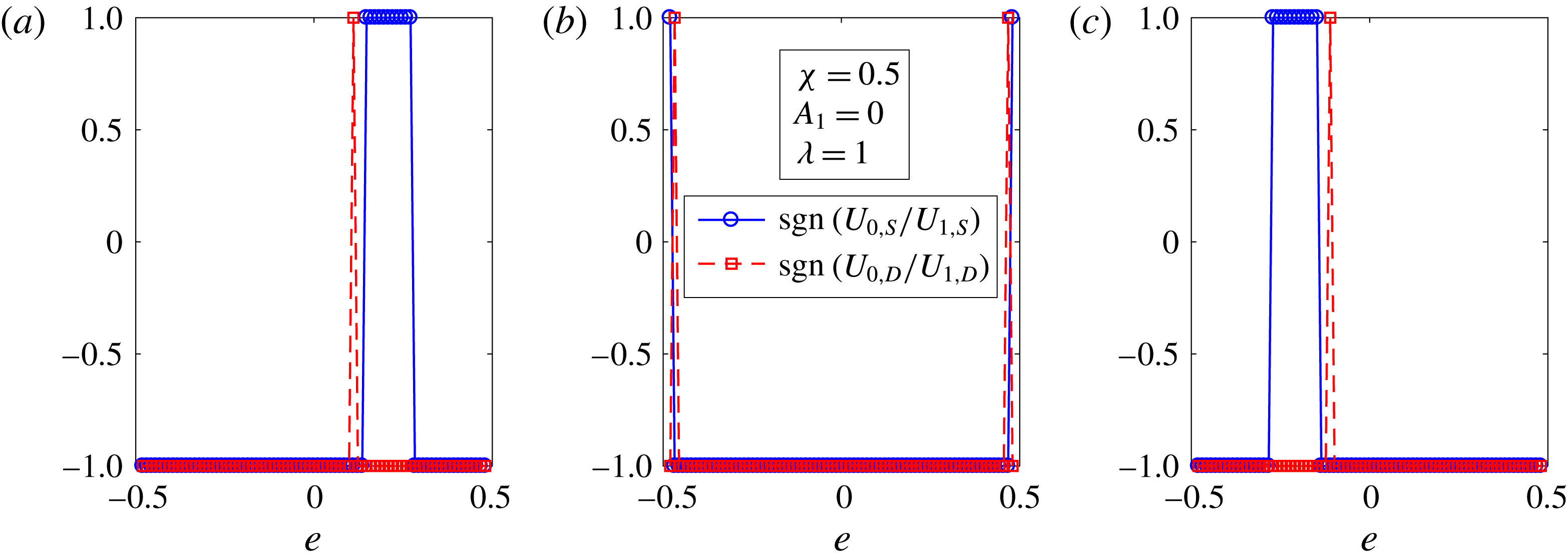
Figure 10. The signs of the ratios
![]() $U_{0,S}/U_{1,S}$
and
$U_{0,S}/U_{1,S}$
and
![]() $U_{0,D}/U_{1,D}$
plotted as a function of the eccentricity
$U_{0,D}/U_{1,D}$
plotted as a function of the eccentricity
![]() $e$
for (a) a pusher
$e$
for (a) a pusher
![]() $(\unicode[STIX]{x1D6FD}=-5)$
, (b) a neutral swimmer
$(\unicode[STIX]{x1D6FD}=-5)$
, (b) a neutral swimmer
![]() $(\unicode[STIX]{x1D6FD}=0)$
and (c) a puller
$(\unicode[STIX]{x1D6FD}=0)$
and (c) a puller
![]() $(\unicode[STIX]{x1D6FD}=5)$
inside a surfactant-laden drop. The size ratio,
$(\unicode[STIX]{x1D6FD}=5)$
inside a surfactant-laden drop. The size ratio,
![]() $\unicode[STIX]{x1D712}$
, and the viscosity ratio,
$\unicode[STIX]{x1D712}$
, and the viscosity ratio,
![]() $\unicode[STIX]{x1D706}$
, are taken as 0.5 and 1 respectively.
$\unicode[STIX]{x1D706}$
, are taken as 0.5 and 1 respectively.
Earlier, we showed that the redistribution of the surfactant decreases the velocity of a swimmer and a drop when the swimmer is located at the centre of the drop. To understand the influence of the surfactant redistribution on the swimmer and drop velocities for an eccentrically located swimmer inside a drop, we plot in figure 10 the ratios
![]() $\text{sgn}(U_{0,S}/U_{1,S})$
and
$\text{sgn}(U_{0,S}/U_{1,S})$
and
![]() $\text{sgn}(U_{0,D}/U_{1,D})$
as a function of the eccentricity. Here,
$\text{sgn}(U_{0,D}/U_{1,D})$
as a function of the eccentricity. Here,
![]() $\text{sgn}(\;)$
denotes the sign function. Since
$\text{sgn}(\;)$
denotes the sign function. Since
![]() $U_{1,S}$
and
$U_{1,S}$
and
![]() $U_{1,D}$
are proportional to
$U_{1,D}$
are proportional to
![]() $Ma$
, and
$Ma$
, and
![]() $Ma>0$
, these plots are valid for all finite values of
$Ma>0$
, these plots are valid for all finite values of
![]() $Ma$
at which the perturbation in
$Ma$
at which the perturbation in
![]() $Pe_{s}$
is valid. A positive (negative) value of the ratio
$Pe_{s}$
is valid. A positive (negative) value of the ratio
![]() $U_{0,S}/U_{1,S}$
means that the surfactant redistribution increases (decreases) the magnitude of the swimmer velocity. One can similarly deduce the relation between the sign of the ratio
$U_{0,S}/U_{1,S}$
means that the surfactant redistribution increases (decreases) the magnitude of the swimmer velocity. One can similarly deduce the relation between the sign of the ratio
![]() $U_{0,D}/U_{1,D}$
and the effect of the surfactant redistribution on the magnitude of the drop velocity. From figure 10, we see that the advection of the surfactant reduces the magnitudes of the swimmer and drop velocities for a swimmer located at the centre of the drop, consistent with the concentric calculations. Even though this trend of surfactant redistribution decreasing the magnitudes of the swimmer and drop velocities holds for most values of the eccentricity, we see that there exist some values of the eccentricity at which the surfactant redistribution increases the magnitude of the swimmer or drop velocity. Moreover, at an eccentrically stable position corresponding to a clean drop, the surfactant redistribution decreases the magnitudes of the swimmer and drop velocities. We note that for eccentric configurations, the drop surface velocity decreases due to the surfactant redistribution, and also the drop surface, swimmer and drop velocities decrease with a decrease in
$U_{0,D}/U_{1,D}$
and the effect of the surfactant redistribution on the magnitude of the drop velocity. From figure 10, we see that the advection of the surfactant reduces the magnitudes of the swimmer and drop velocities for a swimmer located at the centre of the drop, consistent with the concentric calculations. Even though this trend of surfactant redistribution decreasing the magnitudes of the swimmer and drop velocities holds for most values of the eccentricity, we see that there exist some values of the eccentricity at which the surfactant redistribution increases the magnitude of the swimmer or drop velocity. Moreover, at an eccentrically stable position corresponding to a clean drop, the surfactant redistribution decreases the magnitudes of the swimmer and drop velocities. We note that for eccentric configurations, the drop surface velocity decreases due to the surfactant redistribution, and also the drop surface, swimmer and drop velocities decrease with a decrease in
![]() $\unicode[STIX]{x1D706}$
for a clean drop containing a swimmer. For this reason, the observations in figure 10 cannot be explained by studying the influence of the surfactant advection on the drop surface velocity, as was done for the concentric configuration. Motivated by the physical reasoning provided to explain the change in the velocity of a swimmer in a shear-thinning fluid (Montenegro-Johnson, Smith & Loghin Reference Montenegro-Johnson, Smith and Loghin2013; Datt et al.
Reference Datt, Zhu, Elfring and Pak2015) (compared with that in a Newtonian fluid), we analyse the drag and thrust problems separately in the next section to explain the effect of surfactant redistribution on the swimmer and drop velocities, as shown in figure 10.
$\unicode[STIX]{x1D706}$
for a clean drop containing a swimmer. For this reason, the observations in figure 10 cannot be explained by studying the influence of the surfactant advection on the drop surface velocity, as was done for the concentric configuration. Motivated by the physical reasoning provided to explain the change in the velocity of a swimmer in a shear-thinning fluid (Montenegro-Johnson, Smith & Loghin Reference Montenegro-Johnson, Smith and Loghin2013; Datt et al.
Reference Datt, Zhu, Elfring and Pak2015) (compared with that in a Newtonian fluid), we analyse the drag and thrust problems separately in the next section to explain the effect of surfactant redistribution on the swimmer and drop velocities, as shown in figure 10.
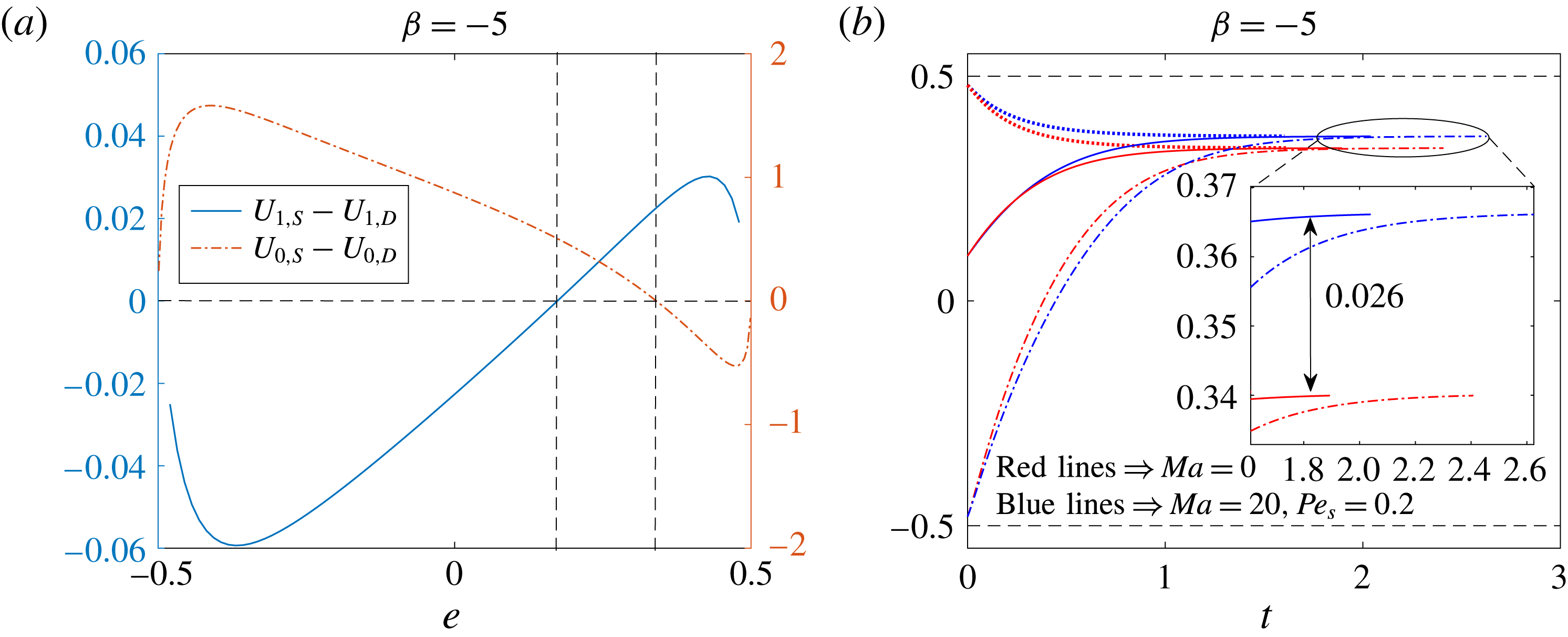
Figure 11. (a) The velocity of a pusher swimmer with respect to a drop at
![]() $O(1)$
(red dash-dotted line) and at
$O(1)$
(red dash-dotted line) and at
![]() $O(Pe_{s})$
(blue solid line) as a function of the eccentricity. The axis for the
$O(Pe_{s})$
(blue solid line) as a function of the eccentricity. The axis for the
![]() $O(Pe_{s})$
relative velocity is on the left while that for the
$O(Pe_{s})$
relative velocity is on the left while that for the
![]() $O(1)$
relative velocity is on the right. Here,
$O(1)$
relative velocity is on the right. Here,
![]() $Ma=1$
. The dashed lines are just for reference. (b) The time evolution of the centre of a pusher swimmer when released from different positions. Here, red lines denote the results for a clean drop, while blue lines denote the results for a surfactant-laden drop with
$Ma=1$
. The dashed lines are just for reference. (b) The time evolution of the centre of a pusher swimmer when released from different positions. Here, red lines denote the results for a clean drop, while blue lines denote the results for a surfactant-laden drop with
![]() $Ma=20$
and
$Ma=20$
and
![]() $Pe_{s}=0.2$
. The inset shows the shift in the location of an eccentrically stable position induced by the advection of the surfactant. The size ratio,
$Pe_{s}=0.2$
. The inset shows the shift in the location of an eccentrically stable position induced by the advection of the surfactant. The size ratio,
![]() $\unicode[STIX]{x1D712}$
, and viscosity ratio,
$\unicode[STIX]{x1D712}$
, and viscosity ratio,
![]() $\unicode[STIX]{x1D706}$
, are taken as 0.5 and 1 respectively. All of the velocities are non-dimensionalized using
$\unicode[STIX]{x1D706}$
, are taken as 0.5 and 1 respectively. All of the velocities are non-dimensionalized using
![]() $U_{sq}=2B_{1}/3$
. The dashed lines indicate the positions at which the swimmer touches the drop.
$U_{sq}=2B_{1}/3$
. The dashed lines indicate the positions at which the swimmer touches the drop.
At an eccentrically stable position corresponding to a clean drop, since the surfactant redistribution reduces the magnitudes of the swimmer and drop velocities by unequal amounts, this stable position shifts due to the surfactant advection. To understand this shift, we plot in figure 11(a) the relative velocity of a pusher swimmer at
![]() $O(1)(U_{0,S}-U_{0,D})$
and at
$O(1)(U_{0,S}-U_{0,D})$
and at
![]() $O(Pe_{s})$
$O(Pe_{s})$
![]() $(U_{1,S}-U_{1,D})$
for various eccentricities. The axis for the
$(U_{1,S}-U_{1,D})$
for various eccentricities. The axis for the
![]() $O(Pe_{s})$
relative velocity is on the left, while that for the
$O(Pe_{s})$
relative velocity is on the left, while that for the
![]() $O(1)$
relative velocity is on the right. As is seen from this figure, at an eccentrically stable position corresponding to a clean drop, the
$O(1)$
relative velocity is on the right. As is seen from this figure, at an eccentrically stable position corresponding to a clean drop, the
![]() $O(1)$
relative velocity is zero while the
$O(1)$
relative velocity is zero while the
![]() $O(Pe_{s})$
relative velocity is positive. Therefore, the eccentrically stable position shifts towards the top surface of the drop due to the surfactant redistribution, as shown in figure 11(b). This figure shows the time evolution of the centre of a pusher swimmer when released from different positions inside a drop. As is seen from the inset of this figure, the time taken by the swimmer to reach an eccentrically stable position depends on its initial position and the presence of the surfactant on the drop. This time scales as
$O(Pe_{s})$
relative velocity is positive. Therefore, the eccentrically stable position shifts towards the top surface of the drop due to the surfactant redistribution, as shown in figure 11(b). This figure shows the time evolution of the centre of a pusher swimmer when released from different positions inside a drop. As is seen from the inset of this figure, the time taken by the swimmer to reach an eccentrically stable position depends on its initial position and the presence of the surfactant on the drop. This time scales as
![]() $t\sim d_{0}/|U_{S}-U_{D}|$
, where
$t\sim d_{0}/|U_{S}-U_{D}|$
, where
![]() $d_{0}$
is the distance between the initial swimmer position and its eccentrically stable position. Hence, the swimmer takes a long (short) time to reach the stable position if it is initially far away from (close enough to) this position; compare the solid and dash-dotted lines of the same colour in the inset of figure 11(b). Moreover, for most of the swimmer positions inside the drop, the surfactant redistribution decreases the magnitude of the relative velocity of the swimmer
$d_{0}$
is the distance between the initial swimmer position and its eccentrically stable position. Hence, the swimmer takes a long (short) time to reach the stable position if it is initially far away from (close enough to) this position; compare the solid and dash-dotted lines of the same colour in the inset of figure 11(b). Moreover, for most of the swimmer positions inside the drop, the surfactant redistribution decreases the magnitude of the relative velocity of the swimmer
![]() $|U_{S}-U_{D}|$
(see figure 11
a). Hence, for a given initial position, a swimmer inside a surfactant-laden drop takes a longer time than one inside a clean drop to reach its eccentrically stable position; compare the blue and red coloured lines that are of the same style.
$|U_{S}-U_{D}|$
(see figure 11
a). Hence, for a given initial position, a swimmer inside a surfactant-laden drop takes a longer time than one inside a clean drop to reach its eccentrically stable position; compare the blue and red coloured lines that are of the same style.
4.3 Drag and thrust
In this section, we analyse the thrust and drag forces on the swimmer and the drop separately to explain the observations in figure 10. As the influence of the surfactant redistribution on the swimmer and drop velocities for a pusher inside a drop at some eccentricity
![]() $e=e_{1}>0$
is the same as that for a puller inside a drop at the eccentricity
$e=e_{1}>0$
is the same as that for a puller inside a drop at the eccentricity
![]() $e=-e_{1}$
, we will only analyse the results for a neutral swimmer and a puller, i.e. figure 10(b,c).
$e=-e_{1}$
, we will only analyse the results for a neutral swimmer and a puller, i.e. figure 10(b,c).
We define the thrust and drag problems for the swimmer as follows. The thrust problem consists of a fixed swimmer, with a slip velocity on its surface, inside a force-free surfactant-laden drop, whereas the drag problem consists of a translating rigid sphere with a velocity
![]() $\boldsymbol{U}_{0,S}$
inside a force-free surfactant-laden drop. We call the hydrodynamic force experienced by the swimmer in the thrust (drag) problem the thrust force (drag force) and denote this force at
$\boldsymbol{U}_{0,S}$
inside a force-free surfactant-laden drop. We call the hydrodynamic force experienced by the swimmer in the thrust (drag) problem the thrust force (drag force) and denote this force at
![]() $O(Pe_{s}^{j})$
by
$O(Pe_{s}^{j})$
by
![]() $F_{j,TS}\boldsymbol{i}_{z}(F_{j,DS}\boldsymbol{i}_{z})$
. Similarly, we define the thrust and drag problems for the drop as follows. The thrust problem consists of a stationary surfactant-covered drop encapsulating a swimmer, whereas the drag problem consists of a surfactant-laden drop engulfing a force-free rigid sphere; the drop itself is translating with a velocity
$F_{j,TS}\boldsymbol{i}_{z}(F_{j,DS}\boldsymbol{i}_{z})$
. Similarly, we define the thrust and drag problems for the drop as follows. The thrust problem consists of a stationary surfactant-covered drop encapsulating a swimmer, whereas the drag problem consists of a surfactant-laden drop engulfing a force-free rigid sphere; the drop itself is translating with a velocity
![]() $\boldsymbol{U}_{0,D}$
. Again, we denote the thrust and drag forces acting on the drop at
$\boldsymbol{U}_{0,D}$
. Again, we denote the thrust and drag forces acting on the drop at
![]() $O(Pe_{s}^{j})$
by
$O(Pe_{s}^{j})$
by
![]() $F_{j,TD}\boldsymbol{i}_{z}$
and
$F_{j,TD}\boldsymbol{i}_{z}$
and
![]() $F_{j,DD}\boldsymbol{i}_{z}$
respectively. If the drag problem for the swimmer were to consist of a rigid sphere translating with a velocity
$F_{j,DD}\boldsymbol{i}_{z}$
respectively. If the drag problem for the swimmer were to consist of a rigid sphere translating with a velocity
![]() $\boldsymbol{U}_{0,S}+Pe_{s}\boldsymbol{U}_{1,S}$
inside a force-free surfactant-laden drop, then the sum of the thrust and drag problems for the swimmer would give the original problem of a swimmer inside a force-free surfactant-laden drop accurate to
$\boldsymbol{U}_{0,S}+Pe_{s}\boldsymbol{U}_{1,S}$
inside a force-free surfactant-laden drop, then the sum of the thrust and drag problems for the swimmer would give the original problem of a swimmer inside a force-free surfactant-laden drop accurate to
![]() $O(Pe_{s})$
. One can think along similar lines regarding the thrust and drag problems for the drop. Since we would like to estimate the sign of
$O(Pe_{s})$
. One can think along similar lines regarding the thrust and drag problems for the drop. Since we would like to estimate the sign of
![]() $U_{1,S}(U_{1,D})$
, we did not include it in the drag problem of the swimmer (drop). As the sum of the
$U_{1,S}(U_{1,D})$
, we did not include it in the drag problem of the swimmer (drop). As the sum of the
![]() $O(1)$
thrust and drag problems for either the swimmer or the drop gives the
$O(1)$
thrust and drag problems for either the swimmer or the drop gives the
![]() $O(1)$
original problem (swimmer inside a clean drop where both swimmer and drop are force-free), we expect
$O(1)$
original problem (swimmer inside a clean drop where both swimmer and drop are force-free), we expect
![]() $F_{0,TS}+F_{0,DS}=0$
and
$F_{0,TS}+F_{0,DS}=0$
and
![]() $F_{0,TD}+F_{0,DD}=0$
. Therefore, only one of the
$F_{0,TD}+F_{0,DD}=0$
. Therefore, only one of the
![]() $O(1)$
thrust and drag forces is an independent quantity.
$O(1)$
thrust and drag forces is an independent quantity.
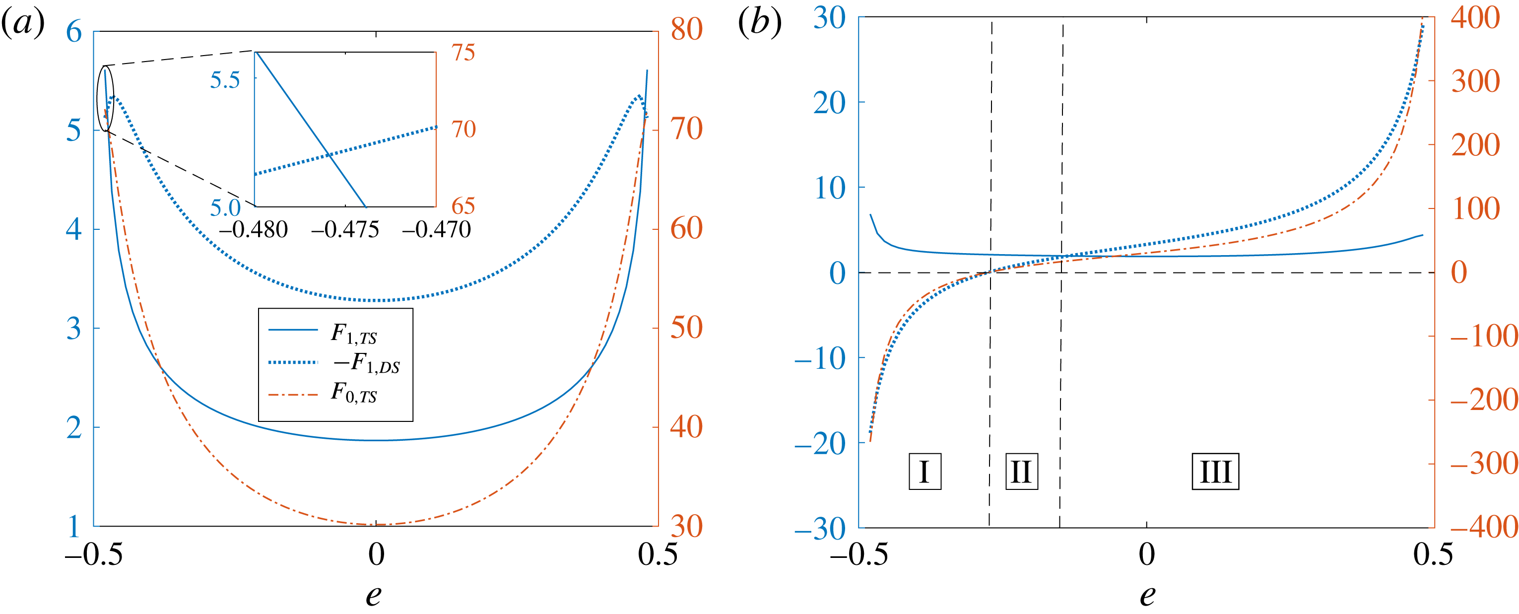
Figure 12. The variation of the thrust and drag forces acting on the swimmer at various orders of
![]() $Pe_{s}$
with the eccentricity for (a) a neutral swimmer
$Pe_{s}$
with the eccentricity for (a) a neutral swimmer
![]() $(\unicode[STIX]{x1D6FD}=0)$
and (b) a puller
$(\unicode[STIX]{x1D6FD}=0)$
and (b) a puller
![]() $(\unicode[STIX]{x1D6FD}=5)$
inside a surfactant-covered drop. The blue solid line, blue dotted line and red dash-dotted line denote the
$(\unicode[STIX]{x1D6FD}=5)$
inside a surfactant-covered drop. The blue solid line, blue dotted line and red dash-dotted line denote the
![]() $O(Pe_{s})$
thrust,
$O(Pe_{s})$
thrust,
![]() $O(Pe_{s})$
(negative) drag and
$O(Pe_{s})$
(negative) drag and
![]() $O(1)$
thrust forces respectively. The axis for the
$O(1)$
thrust forces respectively. The axis for the
![]() $O(Pe_{s})$
forces is on the left, while that for the
$O(Pe_{s})$
forces is on the left, while that for the
![]() $O(1)$
force is on the right.
$O(1)$
force is on the right.
To understand how the surfactant redistribution affects the swimmer velocity for eccentric configurations, we plot the
![]() $O(1)$
thrust,
$O(1)$
thrust,
![]() $O(Pe_{s})$
thrust and (negative of the)
$O(Pe_{s})$
thrust and (negative of the)
![]() $O(Pe_{s})$
drag on the swimmer as a function of the eccentricity in figure 12. Figure 12(a) is for a neutral swimmer, while figure 12(b) is for a puller inside a surfactant-laden drop. The axis for the
$O(Pe_{s})$
drag on the swimmer as a function of the eccentricity in figure 12. Figure 12(a) is for a neutral swimmer, while figure 12(b) is for a puller inside a surfactant-laden drop. The axis for the
![]() $O(Pe_{s})~(O(1))$
forces is on the left (right).
$O(Pe_{s})~(O(1))$
forces is on the left (right).
On analysing the thrust and drag for a neutral swimmer inside a drop, we see from figure 12(a) that the
![]() $O(1)$
thrust,
$O(1)$
thrust,
![]() $O(Pe_{s})$
thrust and (negative of the)
$O(Pe_{s})$
thrust and (negative of the)
![]() $O(Pe_{s})$
drag are all positive, i.e.
$O(Pe_{s})$
drag are all positive, i.e.
![]() $F_{0,TS}>0$
,
$F_{0,TS}>0$
,
![]() $F_{1,TS}>0$
and
$F_{1,TS}>0$
and
![]() $-F_{1,DS}>0$
. Noting that the (negative of the)
$-F_{1,DS}>0$
. Noting that the (negative of the)
![]() $O(1)$
drag is positive, i.e.
$O(1)$
drag is positive, i.e.
![]() $-F_{0,DS}=F_{0,TS}>0$
, we conclude that the surfactant redistribution increases the magnitude of both the thrust and the drag for a neutral swimmer inside a drop. However, since the increase in the magnitude of the drag is more than the increase in the thrust, i.e.
$-F_{0,DS}=F_{0,TS}>0$
, we conclude that the surfactant redistribution increases the magnitude of both the thrust and the drag for a neutral swimmer inside a drop. However, since the increase in the magnitude of the drag is more than the increase in the thrust, i.e.
![]() $-F_{1,DS}>F_{1,TS}$
, for most of the eccentricities, the magnitude of the swimmer velocity should decrease due to the surfactant redistribution for most of the eccentricities, i.e.
$-F_{1,DS}>F_{1,TS}$
, for most of the eccentricities, the magnitude of the swimmer velocity should decrease due to the surfactant redistribution for most of the eccentricities, i.e.
![]() $\text{sgn}(U_{0,S}/U_{1,S})=-1$
. However, at
$\text{sgn}(U_{0,S}/U_{1,S})=-1$
. However, at
![]() $e=\pm 0.48$
, as the increase in the thrust is more than the increase in the magnitude of the drag, i.e.
$e=\pm 0.48$
, as the increase in the thrust is more than the increase in the magnitude of the drag, i.e.
![]() $F_{1,TS}>-F_{1,DS}$
, as shown in the inset of figure 12(a), the magnitude of the swimmer velocity should increase due to the surfactant redistribution, i.e.
$F_{1,TS}>-F_{1,DS}$
, as shown in the inset of figure 12(a), the magnitude of the swimmer velocity should increase due to the surfactant redistribution, i.e.
![]() $\text{sgn}(U_{0,S}/U_{1,S})=+1$
. This behaviour predicted for
$\text{sgn}(U_{0,S}/U_{1,S})=+1$
. This behaviour predicted for
![]() $\text{sgn}(U_{0,S}/U_{1,S})$
from the drag and thrust analysis matches exactly with that reported in figure 10(b).
$\text{sgn}(U_{0,S}/U_{1,S})$
from the drag and thrust analysis matches exactly with that reported in figure 10(b).
On analysing the thrust and drag for a puller inside a drop, we see from figure 12(b) that for eccentricities in regions II and III, the
![]() $O(1)$
thrust force, the
$O(1)$
thrust force, the
![]() $O(Pe_{s})$
thrust and the (negative of the)
$O(Pe_{s})$
thrust and the (negative of the)
![]() $O(Pe_{s})$
drag are positive, i.e.
$O(Pe_{s})$
drag are positive, i.e.
![]() $F_{0,TS}>0$
,
$F_{0,TS}>0$
,
![]() $F_{1,TS}>0$
and
$F_{1,TS}>0$
and
![]() $-F_{1,DS}>0$
. Since
$-F_{1,DS}>0$
. Since
![]() $-F_{0,DS}=F_{0,TS}>0$
, the (negative of the)
$-F_{0,DS}=F_{0,TS}>0$
, the (negative of the)
![]() $O(1)$
drag is positive for the aforementioned eccentricities. Therefore, for these values of the eccentricity, the surfactant redistribution increases the magnitude of both the thrust and the drag. For eccentricities in region III (II), since
$O(1)$
drag is positive for the aforementioned eccentricities. Therefore, for these values of the eccentricity, the surfactant redistribution increases the magnitude of both the thrust and the drag. For eccentricities in region III (II), since
![]() $-F_{1,DS}>F_{1,TS}$
$-F_{1,DS}>F_{1,TS}$
![]() $(-F_{1,DS}<F_{1,TS})$
, the increase in the magnitude of the drag is more (less) than the increase in the thrust; hence, the magnitude of the swimmer velocity should decrease (increase) due to the surfactant redistribution, i.e.
$(-F_{1,DS}<F_{1,TS})$
, the increase in the magnitude of the drag is more (less) than the increase in the thrust; hence, the magnitude of the swimmer velocity should decrease (increase) due to the surfactant redistribution, i.e.
![]() $\text{sgn}(U_{0,S}/U_{1,S})=-1(\text{sgn}(U_{0,S}/U_{1,S})=+1)$
. For eccentricities in region I, the
$\text{sgn}(U_{0,S}/U_{1,S})=-1(\text{sgn}(U_{0,S}/U_{1,S})=+1)$
. For eccentricities in region I, the
![]() $O(1)$
thrust is negative, so the (negative of the)
$O(1)$
thrust is negative, so the (negative of the)
![]() $O(1)$
drag is negative, whereas the
$O(1)$
drag is negative, whereas the
![]() $O(Pe_{s})$
thrust is positive and the (negative of the)
$O(Pe_{s})$
thrust is positive and the (negative of the)
![]() $O(Pe_{s})$
drag is negative, i.e.
$O(Pe_{s})$
drag is negative, i.e.
![]() $F_{0,TS}<0$
,
$F_{0,TS}<0$
,
![]() $-F_{0,DS}<0$
,
$-F_{0,DS}<0$
,
![]() $F_{1,TS}>0$
and
$F_{1,TS}>0$
and
![]() $-F_{1,DS}<0$
. Hence, for these eccentricities, the surfactant redistribution increases the magnitude of the drag but decreases the magnitude of the thrust. This means that for eccentricities in region I, the magnitude of the swimmer velocity should decrease due to the surfactant redistribution, i.e.
$-F_{1,DS}<0$
. Hence, for these eccentricities, the surfactant redistribution increases the magnitude of the drag but decreases the magnitude of the thrust. This means that for eccentricities in region I, the magnitude of the swimmer velocity should decrease due to the surfactant redistribution, i.e.
![]() $\text{sgn}(U_{0,S}/U_{1,S})=-1$
. Again, the behaviour predicted for the variation of
$\text{sgn}(U_{0,S}/U_{1,S})=-1$
. Again, the behaviour predicted for the variation of
![]() $\text{sgn}(U_{0,S}/U_{1,S})$
with the eccentricity from the drag and thrust analysis matches exactly with that reported in figure 10(c).
$\text{sgn}(U_{0,S}/U_{1,S})$
with the eccentricity from the drag and thrust analysis matches exactly with that reported in figure 10(c).
A similar analysis can be carried out to understand the influence of surfactant redistribution on the drop velocity (instead of the swimmer velocity) for eccentric configurations. For this purpose, we plot in figure 13 the
![]() $O(1)$
thrust, the
$O(1)$
thrust, the
![]() $O(Pe_{s})$
thrust and the (negative of the)
$O(Pe_{s})$
thrust and the (negative of the)
![]() $O(Pe_{s})$
drag on the drop for various eccentricities. Again, figure 13(a) is for a neutral swimmer and figure 13(b) is for a puller inside a surfactant-laden drop.
$O(Pe_{s})$
drag on the drop for various eccentricities. Again, figure 13(a) is for a neutral swimmer and figure 13(b) is for a puller inside a surfactant-laden drop.
We analyse the thrust and drag forces acting on a drop containing a neutral swimmer, as plotted in figure 13(a). For
![]() $|e|<0.466$
, we see from this figure that the
$|e|<0.466$
, we see from this figure that the
![]() $O(1)$
thrust is positive, so the (negative of the)
$O(1)$
thrust is positive, so the (negative of the)
![]() $O(1)$
drag is also positive, i.e.
$O(1)$
drag is also positive, i.e.
![]() $-F_{0,DD}=F_{0,TD}>0$
. Moreover, for these eccentricities, the
$-F_{0,DD}=F_{0,TD}>0$
. Moreover, for these eccentricities, the
![]() $O(Pe_{s})$
thrust is negative and the (negative of the)
$O(Pe_{s})$
thrust is negative and the (negative of the)
![]() $O(Pe_{s})$
drag is positive, i.e.
$O(Pe_{s})$
drag is positive, i.e.
![]() $F_{1,TD}<0$
,
$F_{1,TD}<0$
,
![]() $-F_{1,DD}>0$
. Hence, for
$-F_{1,DD}>0$
. Hence, for
![]() $|e|<0.466$
, the surfactant redistribution decreases the thrust but increases the magnitude of the drag, so the drop velocity should decrease, i.e.
$|e|<0.466$
, the surfactant redistribution decreases the thrust but increases the magnitude of the drag, so the drop velocity should decrease, i.e.
![]() $\text{sgn}(U_{0,D}/U_{1,D})=-1$
(compare with figure 10
b). For
$\text{sgn}(U_{0,D}/U_{1,D})=-1$
(compare with figure 10
b). For
![]() $|e|\in (0.466,0.47)$
, there exist some eccentricities (see the inset of figure 13
a) at which the
$|e|\in (0.466,0.47)$
, there exist some eccentricities (see the inset of figure 13
a) at which the
![]() $O(1)$
thrust, the (negative of the)
$O(1)$
thrust, the (negative of the)
![]() $O(1)$
drag, the
$O(1)$
drag, the
![]() $O(Pe_{s})$
thrust and the (negative of the)
$O(Pe_{s})$
thrust and the (negative of the)
![]() $O(Pe_{s})$
drag are all negative, i.e.
$O(Pe_{s})$
drag are all negative, i.e.
![]() $-F_{0,DD}=F_{0,TD}<0$
,
$-F_{0,DD}=F_{0,TD}<0$
,
![]() $F_{1,TD}<0$
,
$F_{1,TD}<0$
,
![]() $-F_{1,DD}<0$
. Therefore, the surfactant redistribution increases the magnitude of both the thrust and the drag. However, since the increase in the magnitude of the thrust is more than the increase in the magnitude of the drag for some
$-F_{1,DD}<0$
. Therefore, the surfactant redistribution increases the magnitude of both the thrust and the drag. However, since the increase in the magnitude of the thrust is more than the increase in the magnitude of the drag for some
![]() $|e|\in (0.466,0.47)$
, i.e.
$|e|\in (0.466,0.47)$
, i.e.
![]() $|F_{1,TD}|>|F_{1,DD}|$
, the drop velocity should increase, i.e.
$|F_{1,TD}|>|F_{1,DD}|$
, the drop velocity should increase, i.e.
![]() $\text{sgn}(U_{0,D}/U_{1,D})=+1$
. This behaviour predicted for
$\text{sgn}(U_{0,D}/U_{1,D})=+1$
. This behaviour predicted for
![]() $\text{sgn}(U_{0,D}/U_{1,D})$
from the drag and thrust analysis matches with that reported in figure 10(b).
$\text{sgn}(U_{0,D}/U_{1,D})$
from the drag and thrust analysis matches with that reported in figure 10(b).
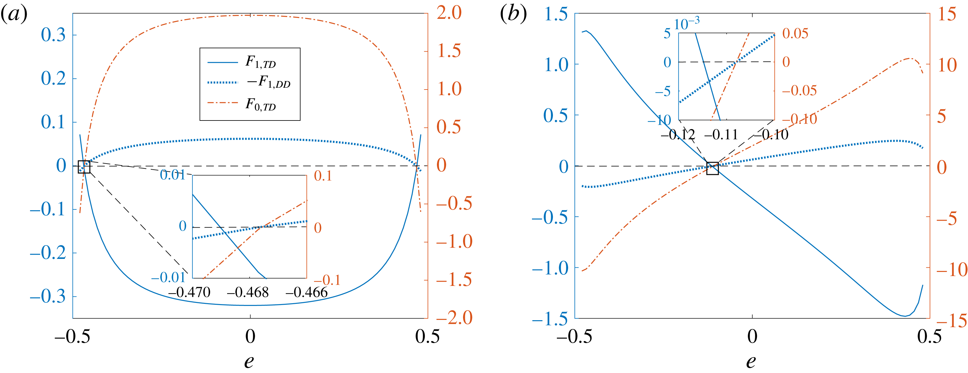
Figure 13. The variation of the thrust and drag forces acting on the drop at various orders of
![]() $Pe_{s}$
with the eccentricity for (a) a neutral swimmer
$Pe_{s}$
with the eccentricity for (a) a neutral swimmer
![]() $(\unicode[STIX]{x1D6FD}=0)$
and (b) a puller
$(\unicode[STIX]{x1D6FD}=0)$
and (b) a puller
![]() $(\unicode[STIX]{x1D6FD}=5)$
inside a surfactant-covered drop. The blue solid line, blue dotted line and red dash-dotted line denote the
$(\unicode[STIX]{x1D6FD}=5)$
inside a surfactant-covered drop. The blue solid line, blue dotted line and red dash-dotted line denote the
![]() $O(Pe_{s})$
thrust,
$O(Pe_{s})$
thrust,
![]() $O(Pe_{s})$
(negative) drag and
$O(Pe_{s})$
(negative) drag and
![]() $O(1)$
thrust forces respectively. The axis for the
$O(1)$
thrust forces respectively. The axis for the
![]() $O(Pe_{s})$
forces is on the left while that for the
$O(Pe_{s})$
forces is on the left while that for the
![]() $O(1)$
force is on the right.
$O(1)$
force is on the right.
We finally analyse the thrust and drag forces acting on a drop containing a puller swimmer, as plotted in figure 13(b). For
![]() $e>-0.1$
, the
$e>-0.1$
, the
![]() $O(1)$
thrust, the (negative of the)
$O(1)$
thrust, the (negative of the)
![]() $O(1)$
drag and the negative of the
$O(1)$
drag and the negative of the
![]() $O(Pe_{s})$
drag are positive while the
$O(Pe_{s})$
drag are positive while the
![]() $O(Pe_{s})$
thrust is negative, i.e.
$O(Pe_{s})$
thrust is negative, i.e.
![]() $-F_{0,DD}=F_{0,TD}>0$
,
$-F_{0,DD}=F_{0,TD}>0$
,
![]() $-F_{1,DD}>0$
,
$-F_{1,DD}>0$
,
![]() $F_{1,TD}<0$
. Moreover, for
$F_{1,TD}<0$
. Moreover, for
![]() $e<-0.12$
, the
$e<-0.12$
, the
![]() $O(1)$
thrust, the (negative of the)
$O(1)$
thrust, the (negative of the)
![]() $O(1)$
drag and the (negative of the)
$O(1)$
drag and the (negative of the)
![]() $O(Pe_{s})$
drag are negative while the
$O(Pe_{s})$
drag are negative while the
![]() $O(Pe_{s})$
thrust is positive, i.e.
$O(Pe_{s})$
thrust is positive, i.e.
![]() $-F_{0,DD}=F_{0,TD}<0$
,
$-F_{0,DD}=F_{0,TD}<0$
,
![]() $-F_{1,DD}<0$
,
$-F_{1,DD}<0$
,
![]() $F_{1,TD}>0$
. Hence, for
$F_{1,TD}>0$
. Hence, for
![]() $e<-0.12$
or
$e<-0.12$
or
![]() $e>-0.1$
, the surfactant redistribution decreases the magnitude of the thrust but increases the magnitude of the drag, so the drop velocity should decrease, i.e.
$e>-0.1$
, the surfactant redistribution decreases the magnitude of the thrust but increases the magnitude of the drag, so the drop velocity should decrease, i.e.
![]() $\text{sgn}(U_{0,D}/U_{1,D})=-1$
(compare with figure 10
c). For
$\text{sgn}(U_{0,D}/U_{1,D})=-1$
(compare with figure 10
c). For
![]() $e\in (-0.12,-0.1)$
, there exist some eccentricities at which the
$e\in (-0.12,-0.1)$
, there exist some eccentricities at which the
![]() $O(1)$
thrust, the (negative of the)
$O(1)$
thrust, the (negative of the)
![]() $O(1)$
drag, the
$O(1)$
drag, the
![]() $O(Pe_{s})$
thrust and the (negative of the)
$O(Pe_{s})$
thrust and the (negative of the)
![]() $O(Pe_{s})$
drag are all negative. Therefore, the surfactant redistribution increases the magnitude of both the thrust and the drag. Moreover, for some
$O(Pe_{s})$
drag are all negative. Therefore, the surfactant redistribution increases the magnitude of both the thrust and the drag. Moreover, for some
![]() $e\in (-0.12,-0.1)$
, as the increase in the magnitude of the thrust is more than the increase in the magnitude of the drag, i.e.
$e\in (-0.12,-0.1)$
, as the increase in the magnitude of the thrust is more than the increase in the magnitude of the drag, i.e.
![]() $|F_{1,TD}|>|F_{1,DD}|$
, the drop velocity increases due to surfactant redistribution, i.e.
$|F_{1,TD}|>|F_{1,DD}|$
, the drop velocity increases due to surfactant redistribution, i.e.
![]() $\text{sgn}(U_{0,D}/U_{1,D})=+1$
. Again, the behaviour predicted for the variation of
$\text{sgn}(U_{0,D}/U_{1,D})=+1$
. Again, the behaviour predicted for the variation of
![]() $\text{sgn}(U_{0,D}/U_{1,D})$
with the eccentricity from the drag and thrust analysis matches with that reported in figure 10(c).
$\text{sgn}(U_{0,D}/U_{1,D})$
with the eccentricity from the drag and thrust analysis matches with that reported in figure 10(c).
4.4 Can a time-reversible swimmer inside a surfactant-laden drop have a net motion?
We see that the only nonlinearity in the governing equations and the boundary conditions occurs in the surfactant transport (2.9). However, this nonlinearity does not appear in the perturbed surfactant transport equations until the equation at
![]() $O(Pe_{s}^{2})$
, (2.21). Hence, the governing equations and the boundary conditions at
$O(Pe_{s}^{2})$
, (2.21). Hence, the governing equations and the boundary conditions at
![]() $O(1)$
and
$O(1)$
and
![]() $O(Pe_{s})$
are linear in the squirming modes, but not those at
$O(Pe_{s})$
are linear in the squirming modes, but not those at
![]() $O(Pe_{s}^{2})$
. For this reason, the swimmer and drop velocities at
$O(Pe_{s}^{2})$
. For this reason, the swimmer and drop velocities at
![]() $O(1)$
and
$O(1)$
and
![]() $O(Pe_{s})$
should be linear in the swimming modes
$O(Pe_{s})$
should be linear in the swimming modes
![]() $B_{1}$
,
$B_{1}$
,
![]() $B_{2}\ldots$
, but these velocities at
$B_{2}\ldots$
, but these velocities at
![]() $O(Pe_{s}^{2})$
should be nonlinear. Therefore, if these swimming modes are time-periodic with zero time average (such a swimmer is called a time-reversible swimmer), the leading-order contribution to the time-averaged swimmer and drop velocities should come from the
$O(Pe_{s}^{2})$
should be nonlinear. Therefore, if these swimming modes are time-periodic with zero time average (such a swimmer is called a time-reversible swimmer), the leading-order contribution to the time-averaged swimmer and drop velocities should come from the
![]() $O(Pe_{s}^{2})$
problem. Therefore, it seems that the swimmer and drop might propel with non-zero time-averaged velocities even if the swimmer is time-reversible due to the advection of the surfactant on the surface of the drop. This is a remarkable result since it provides a method to escape from the constraints of the scallop theorem, which can have potential applications in the motion of synthetic swimmers near interfaces, as the interfaces are inevitably covered with some impurities.
$O(Pe_{s}^{2})$
problem. Therefore, it seems that the swimmer and drop might propel with non-zero time-averaged velocities even if the swimmer is time-reversible due to the advection of the surfactant on the surface of the drop. This is a remarkable result since it provides a method to escape from the constraints of the scallop theorem, which can have potential applications in the motion of synthetic swimmers near interfaces, as the interfaces are inevitably covered with some impurities.
We illustrate the physical reasoning provided earlier by deriving the time-averaged swimmer and drop velocities of a two-mode time-reversible swimmer, initially located at the centre of the surfactant-laden drop. Since
![]() $U_{S}>U_{D}$
for the concentric configuration, the swimmer never stays at the centre of the drop. However, if the time period of the swimming modes is much smaller than the time taken by the swimmer or the drop to traverse a drop radius, i.e.
$U_{S}>U_{D}$
for the concentric configuration, the swimmer never stays at the centre of the drop. However, if the time period of the swimming modes is much smaller than the time taken by the swimmer or the drop to traverse a drop radius, i.e.
![]() $T=2\unicode[STIX]{x03C0}/\unicode[STIX]{x1D714}\ll a/U_{sq}$
(
$T=2\unicode[STIX]{x03C0}/\unicode[STIX]{x1D714}\ll a/U_{sq}$
(
![]() $T$
and
$T$
and
![]() $\unicode[STIX]{x1D714}$
are the time period and the angular frequency of the swimming modes), then the eccentricity changes negligibly during one time period. In this case, we can calculate the time-averaged swimmer and drop velocities by fixing the eccentricity at its initial value. Hence, the time-averaged swimmer and drop velocities
$\unicode[STIX]{x1D714}$
are the time period and the angular frequency of the swimming modes), then the eccentricity changes negligibly during one time period. In this case, we can calculate the time-averaged swimmer and drop velocities by fixing the eccentricity at its initial value. Hence, the time-averaged swimmer and drop velocities
can be simplified as
Since the swimmer is at the centre of the drop at
![]() $t=0$
, i.e.
$t=0$
, i.e.
![]() $e(0)=0$
, we have
$e(0)=0$
, we have
Here, we denote the swimmer and drop velocities by
![]() $U_{S}(e(t);t)$
and
$U_{S}(e(t);t)$
and
![]() $U_{D}(e(t);t)$
respectively. This is because as the time progresses, the eccentricity changes, which in turn modifies the swimmer and drop velocities. Moreover, for a fixed eccentricity,
$U_{D}(e(t);t)$
respectively. This is because as the time progresses, the eccentricity changes, which in turn modifies the swimmer and drop velocities. Moreover, for a fixed eccentricity,
![]() $U_{S}$
and
$U_{S}$
and
![]() $U_{D}$
can change with time since the swimming modes are time-dependent. Denoting
$U_{D}$
can change with time since the swimming modes are time-dependent. Denoting
![]() $(1/T)\int _{0}^{T}U(0;t)\,\text{d}t$
by
$(1/T)\int _{0}^{T}U(0;t)\,\text{d}t$
by
![]() $\langle U|_{e=0}\rangle$
, we have
$\langle U|_{e=0}\rangle$
, we have
Here,
![]() $(\,)|_{e=0}$
denotes the quantity when the swimmer is at the centre of the drop, and hence the expressions for
$(\,)|_{e=0}$
denotes the quantity when the swimmer is at the centre of the drop, and hence the expressions for
![]() $U_{0,S}|_{e=0}$
,
$U_{0,S}|_{e=0}$
,
![]() $U_{0,D}|_{e=0}$
,
$U_{0,D}|_{e=0}$
,
![]() $U_{1,S}|_{e=0}$
,
$U_{1,S}|_{e=0}$
,
![]() $U_{1,D}|_{e=0}$
,
$U_{1,D}|_{e=0}$
,
![]() $U_{2,S}|_{e=0}$
and
$U_{2,S}|_{e=0}$
and
![]() $U_{2,D}|_{e=0}$
are given by (4.3)–(4.6), (B 31)–(B 32). From (4.3)–(4.6), we see that
$U_{2,D}|_{e=0}$
are given by (4.3)–(4.6), (B 31)–(B 32). From (4.3)–(4.6), we see that
![]() $U_{0,S}|_{e=0}$
,
$U_{0,S}|_{e=0}$
,
![]() $U_{0,D}|_{e=0}$
,
$U_{0,D}|_{e=0}$
,
![]() $U_{1,S}|_{e=0}$
and
$U_{1,S}|_{e=0}$
and
![]() $U_{1,D}|_{e=0}$
are linear in the swimming modes. Moreover, since the swimming modes are time-periodic with zero time average, i.e.
$U_{1,D}|_{e=0}$
are linear in the swimming modes. Moreover, since the swimming modes are time-periodic with zero time average, i.e.
![]() $\langle A_{n}\rangle =\langle B_{n}\rangle =0$
, we deduce that
$\langle A_{n}\rangle =\langle B_{n}\rangle =0$
, we deduce that
Hence, the equations for the time-averaged swimmer and drop velocities simplify to
Using (B 31)–(B 32) along with the time reversibility of the swimming modes, we derive
where
 $$\begin{eqnarray}\displaystyle \left.\begin{array}{@{}c@{}}\displaystyle K_{1}=\frac{2}{5}\frac{(\unicode[STIX]{x1D712}^{4}+\unicode[STIX]{x1D712}^{3}+\unicode[STIX]{x1D712}^{2}+\unicode[STIX]{x1D712}+1)}{(\unicode[STIX]{x1D712}+1)}J_{1},\\ \displaystyle J_{1}=\frac{(15\unicode[STIX]{x1D712}^{4}+45\unicode[STIX]{x1D712}^{3}+55\unicode[STIX]{x1D712}^{2}+45\unicode[STIX]{x1D712}+15)\unicode[STIX]{x1D712}^{5}\unicode[STIX]{x1D706}^{2}Ma(\unicode[STIX]{x1D712}^{2}-1)}{36((\unicode[STIX]{x1D706}-1)\unicode[STIX]{x1D712}^{5}+3/2\unicode[STIX]{x1D706}+1)^{2}\left(\begin{array}{@{}l@{}}\displaystyle (\unicode[STIX]{x1D706}-1)\unicode[STIX]{x1D712}^{7}+(3\unicode[STIX]{x1D706}-3)\unicode[STIX]{x1D712}^{6}+(6\unicode[STIX]{x1D706}-6)\unicode[STIX]{x1D712}^{5}+({\textstyle \frac{15}{2}}\unicode[STIX]{x1D706}-{\textstyle \frac{15}{4}})\unicode[STIX]{x1D712}^{4}\\ \displaystyle +\,({\textstyle \frac{15}{2}}\unicode[STIX]{x1D706}+{\textstyle \frac{15}{4}})\unicode[STIX]{x1D712}^{3}+(6\unicode[STIX]{x1D706}+6)\unicode[STIX]{x1D712}^{2}+(3\unicode[STIX]{x1D706}+3)\unicode[STIX]{x1D712}+\unicode[STIX]{x1D706}+1\end{array}\right).}\end{array}\right\} & & \displaystyle \nonumber\\ \displaystyle & & \displaystyle\end{eqnarray}$$
As
![]() $\langle B_{1}B_{2}\rangle$
is non-zero for non-orthogonal time-periodic functions with zero time average
$\langle B_{1}B_{2}\rangle$
is non-zero for non-orthogonal time-periodic functions with zero time average
![]() $B_{1}(t)$
and
$B_{1}(t)$
and
![]() $B_{2}(t)$
, we see from (4.25) that the time-averaged swimmer and drop velocities of a time-reversible swimmer inside a drop are non-zero at
$B_{2}(t)$
, we see from (4.25) that the time-averaged swimmer and drop velocities of a time-reversible swimmer inside a drop are non-zero at
![]() $O(Pe_{s}^{2})$
. Therefore, the surfactant advection on the drop surface enables a drop containing a time-reversible swimmer to evade the scallop theorem, thereby leading to a time-averaged propulsion of the swimmer and the drop.
$O(Pe_{s}^{2})$
. Therefore, the surfactant advection on the drop surface enables a drop containing a time-reversible swimmer to evade the scallop theorem, thereby leading to a time-averaged propulsion of the swimmer and the drop.
5 Conclusions
We have studied the motion of a spherical swimmer inside a surfactant-laden drop for axisymmetric configurations by expanding the variables in terms of the surface Péclet number
![]() $(Pe_{s})$
, under the assumption of zero Reynolds number. This small-surface-Péclet analysis is valid when small drops (of size
$(Pe_{s})$
, under the assumption of zero Reynolds number. This small-surface-Péclet analysis is valid when small drops (of size
![]() $1{-}100~\unicode[STIX]{x03BC}\text{m}$
), covered with small sized surfactants (Brenner & Leal Reference Brenner and Leal1978, Reference Brenner and Leal1982), contain small microswimmers (of size
$1{-}100~\unicode[STIX]{x03BC}\text{m}$
), covered with small sized surfactants (Brenner & Leal Reference Brenner and Leal1978, Reference Brenner and Leal1982), contain small microswimmers (of size
![]() $1{-}10~\unicode[STIX]{x03BC}\text{m}$
) whose speed in an unbounded fluid is small
$1{-}10~\unicode[STIX]{x03BC}\text{m}$
) whose speed in an unbounded fluid is small
![]() $({\approx}1{-}100~\unicode[STIX]{x03BC}\text{m}~\text{s}^{-1})$
. Thermal noise in experiments may change the orientation of the swimmer from the axisymmetric configuration. Numerical studies, not in the scope of this paper, are needed to investigate the stability of this configuration.
$({\approx}1{-}100~\unicode[STIX]{x03BC}\text{m}~\text{s}^{-1})$
. Thermal noise in experiments may change the orientation of the swimmer from the axisymmetric configuration. Numerical studies, not in the scope of this paper, are needed to investigate the stability of this configuration.
For a two-mode squirmer inside a drop, the surfactant redistribution can either increase or decrease the magnitudes of the swimmer and drop velocities, depending on the value of the eccentricity. This was explained using the drag and thrust decomposition for the swimmer and the drop separately. Due to the surfactant redistribution, the magnitude of the drag on the swimmer or the drop increases at all eccentricities, but the magnitude of the thrust increases for some eccentricities while decreasing at other eccentricities. When the increase in the magnitude of the thrust is more than the increase in the magnitude of the drag, the magnitude of the swimmer or drop velocity increases due to the surfactant redistribution. If the increase in the magnitude of the thrust is less than the increase in the magnitude of the drag or if the magnitude of the thrust decreases due to the surfactant redistribution, the magnitude of the swimmer or drop velocity decreases.
The far-field representation of a clean drop engulfing a pusher swimmer at its centre is a puller; the strength of this far field is reduced if the drop is covered with a surfactant. Due to the advection of the surfactant on the drop surface, the time-reversible swimmer and the drop, within which the swimmer is engulfed, propel in a time-averaged sense by escaping from the constraints of the scallop theorem. Hence, one can use simple time-reversible swimmers (Gagnon et al. Reference Gagnon, Keim, Shen and Arratia2014) instead of sophisticated helical swimmers such as ABF (Ding et al. Reference Ding, Qiu, Casadevall i Solvas, Chiu, Nelson and Demello2016) (which are not time-reversible) to transport either the contents of the drop or the drop itself.
Inside a clean drop, a two-mode squirmer with
![]() $\unicode[STIX]{x1D6FD}<\unicode[STIX]{x1D6FD}_{c}$
(
$\unicode[STIX]{x1D6FD}<\unicode[STIX]{x1D6FD}_{c}$
(
![]() $\unicode[STIX]{x1D6FD}$
is the ratio of the squirming modes) achieves an eccentrically stable configuration (where the velocity of the swimmer is equal to the velocity of the drop), while squirmers with
$\unicode[STIX]{x1D6FD}$
is the ratio of the squirming modes) achieves an eccentrically stable configuration (where the velocity of the swimmer is equal to the velocity of the drop), while squirmers with
![]() $\unicode[STIX]{x1D6FD}>\unicode[STIX]{x1D6FD}_{c}$
move to the top or bottom surface of the drop. Here,
$\unicode[STIX]{x1D6FD}>\unicode[STIX]{x1D6FD}_{c}$
move to the top or bottom surface of the drop. Here,
![]() $\unicode[STIX]{x1D6FD}_{c}$
is negative and depends on the viscosity ratio and the size ratio. The effect of surfactant redistribution is to shift the eccentrically stable position, achieved by swimmers with
$\unicode[STIX]{x1D6FD}_{c}$
is negative and depends on the viscosity ratio and the size ratio. The effect of surfactant redistribution is to shift the eccentrically stable position, achieved by swimmers with
![]() $\unicode[STIX]{x1D6FD}<\unicode[STIX]{x1D6FD}_{c}$
, towards the top surface of the drop, albeit this shift is very small.
$\unicode[STIX]{x1D6FD}<\unicode[STIX]{x1D6FD}_{c}$
, towards the top surface of the drop, albeit this shift is very small.
Acknowledgements
V.A.S. would like to thank Dr U. Ghosh and Dr S. Mandal for useful discussions. This research was supported by a grant from the National Science Foundation [CBET-1700961].
Appendix A. Linear equations obtained while satisfying (2.12)–(2.18) for the concentric configuration
Enforcing the boundary condition on the surface of the swimmer, (2.12), we obtain
 $$\begin{eqnarray}\displaystyle & & \displaystyle \left[\begin{array}{@{}c@{}}\displaystyle -\frac{(n+3)}{2}\bar{p}_{j,n}^{(1)}\unicode[STIX]{x1D712}^{n+1}-\frac{(n+1)}{2}\bar{\unicode[STIX]{x1D719}}_{j,n}^{(1)}\unicode[STIX]{x1D712}^{n-1}\\ \displaystyle +\frac{(n-2)}{2}\bar{p}_{j,-n-1}^{(1)}\unicode[STIX]{x1D712}^{-n}+\frac{n}{2}\bar{\unicode[STIX]{x1D719}}_{j,-n-1}^{(1)}\unicode[STIX]{x1D712}^{-n-2}\end{array}\right]=\frac{2n+1}{4}\int _{-1}^{1}v_{j,\unicode[STIX]{x1D703}}^{(1)}(r=\unicode[STIX]{x1D712})P_{n}^{1}(\unicode[STIX]{x1D707})\,\text{d}\unicode[STIX]{x1D707}\nonumber\\ \displaystyle & & \displaystyle \quad =\frac{n(n+1)(2n+1)}{8}\int _{-1}^{1}v_{j,\unicode[STIX]{x1D703}}^{(1)}(r=\unicode[STIX]{x1D712})V_{n}(\unicode[STIX]{x1D707})\,\text{d}\unicode[STIX]{x1D707}.\end{eqnarray}$$
For the swimmer and drop to be force-free, we derive respectively
For the flow field far away from the drop to approach the negative of the velocity of the drop, we obtain
 $$\begin{eqnarray}\displaystyle \left.\begin{array}{@{}c@{}}\displaystyle \bar{\unicode[STIX]{x1D719}}_{j,n}^{(2)}=0,\quad \text{for }n\geqslant 2,\\ \displaystyle \bar{p}_{j,n}^{(2)}=0,\quad \text{for }n\geqslant -1,\\ \displaystyle \bar{\unicode[STIX]{x1D719}}_{j,1}^{(2)}=-U_{j,D}.\end{array}\right\} & & \displaystyle\end{eqnarray}$$
In order to satisfy the boundary conditions on the surface of the drop, (2.16)–(2.18), we obtain respectively
 $$\begin{eqnarray}\displaystyle & & \displaystyle -\frac{(n+3)}{2}(\,\bar{p}_{j,n}^{(1)}-\bar{p}_{j,n}^{(2)})-\frac{(n+1)}{2}(\bar{\unicode[STIX]{x1D719}}_{j,n}^{(1)}-\bar{\unicode[STIX]{x1D719}}_{j,n}^{(2)})\nonumber\\ \displaystyle & & \displaystyle \quad +\,\frac{(n-2)}{2}(\bar{p}_{j,-n-1}^{(1)}-\,\bar{p}_{j,-n-1}^{(2)})+\frac{n}{2}(\bar{\unicode[STIX]{x1D719}}_{j,-n-1}^{(1)}-\bar{\unicode[STIX]{x1D719}}_{j,-n-1}^{(2)})=0,\end{eqnarray}$$
 $$\begin{eqnarray}\displaystyle & & \displaystyle (n^{2}-1)(-\bar{\unicode[STIX]{x1D719}}_{j,n}^{(2)}+\unicode[STIX]{x1D706}\bar{\unicode[STIX]{x1D719}}_{j,n}^{(1)})+n(n+2)(-\bar{p}_{j,n}^{(2)}+\unicode[STIX]{x1D706}\bar{p}_{j,n}^{(1)})+n(n+2)(-\bar{\unicode[STIX]{x1D719}}_{j,-n-1}^{(2)}+\unicode[STIX]{x1D706}\bar{\unicode[STIX]{x1D719}}_{j,-n-1}^{(1)})\nonumber\\ \displaystyle & & \displaystyle \quad +\,(n^{2}-1)(-\bar{p}_{j,-n-1}^{(2)}+\unicode[STIX]{x1D706}\bar{p}_{j,-n-1}^{(1)})=-Ma\times \frac{n(n+1)}{2}\unicode[STIX]{x1D6E4}_{j,n}.\end{eqnarray}$$
These equations for
![]() $n=0$
and 1 are first solved to determine the swimmer and drop velocities along with some unknown constants in the flow fields. These equations for
$n=0$
and 1 are first solved to determine the swimmer and drop velocities along with some unknown constants in the flow fields. These equations for
![]() $n\geqslant 2$
are then solved to determine the remaining constants and hence the flow fields in both phases.
$n\geqslant 2$
are then solved to determine the remaining constants and hence the flow fields in both phases.
Appendix B. Flow field due to a ‘squirmer’ at the centre of a drop at various orders of
 $Pe_{s}$
In this section, we provide the expressions for the constants encountered in the velocity components along with the swimmer and drop velocities at
![]() $O(1)$
,
$O(1)$
,
![]() $O(Pe_{s})$
and
$O(Pe_{s})$
and
![]() $O(Pe_{s}^{2})$
. We note that the flow field, swimmer and the drop velocities at
$O(Pe_{s}^{2})$
. We note that the flow field, swimmer and the drop velocities at
![]() $O(1)$
and
$O(1)$
and
![]() $O(Pe_{s})$
are derived for a general
$O(Pe_{s})$
are derived for a general
![]() $n$
-mode squirmer. At
$n$
-mode squirmer. At
![]() $O(Pe_{s}^{2})$
, we derived the swimmer and drop velocities for a squirmer having few modes, namely
$O(Pe_{s}^{2})$
, we derived the swimmer and drop velocities for a squirmer having few modes, namely
![]() $A_{1}$
,
$A_{1}$
,
![]() $A_{2}$
,
$A_{2}$
,
![]() $A_{3}$
,
$A_{3}$
,
![]() $B_{1}$
,
$B_{1}$
,
![]() $B_{2}$
and
$B_{2}$
and
![]() $B_{3}$
.
$B_{3}$
.
B.1 Flow field at
 $O(1)$
For
![]() $n=0,1$
, we have
$n=0,1$
, we have
For
![]() $n\geqslant 2$
, we have
$n\geqslant 2$
, we have
 $$\begin{eqnarray}\displaystyle \bar{p}_{0,-n-1}^{(2)}=2\frac{\left(\begin{array}{@{}l@{}}\displaystyle -(n+3/2)(A_{n}n+A_{n}+2B_{n})\unicode[STIX]{x1D712}^{3n-1}+(n-1/2)(A_{n}n+3A_{n}+2B_{n})\unicode[STIX]{x1D712}^{3n+1}\\ \displaystyle +\,(n-1/2)(A_{n}n-2B_{n})\unicode[STIX]{x1D712}^{n-2}-(A_{n}n-2A_{n}-2B_{n})\unicode[STIX]{x1D712}^{n}(n+3/2)\end{array}\right)\unicode[STIX]{x1D712}^{3}\unicode[STIX]{x1D706}}{\left(\begin{array}{@{}l@{}}\displaystyle 4(n+1/2)(n-\unicode[STIX]{x1D706}+1/2)\unicode[STIX]{x1D712}^{4+2n}+(-8n^{2}-8n+6)\unicode[STIX]{x1D712}^{2+2n}\\ \displaystyle +\,(4\unicode[STIX]{x1D706}-4)\unicode[STIX]{x1D712}^{4n+3}+4(n+1/2)(n+\unicode[STIX]{x1D706}+1/2)\unicode[STIX]{x1D712}^{2n}-4\unicode[STIX]{x1D712}(\unicode[STIX]{x1D706}+1)\end{array}\right)}, & & \displaystyle \nonumber\\ \displaystyle & & \displaystyle\end{eqnarray}$$
 $$\begin{eqnarray}\displaystyle \bar{p}_{0,-n-1}^{(1)}=-2\frac{\unicode[STIX]{x1D712}^{3}\left(\begin{array}{@{}l@{}}\displaystyle -(A_{n}n+3A_{n}+2B_{n})(n-\unicode[STIX]{x1D706}+1/2)\unicode[STIX]{x1D712}^{3n+1}\\ \displaystyle +\,(n+3/2)(A_{n}n+A_{n}+2B_{n})\unicode[STIX]{x1D712}^{3n-1}+\unicode[STIX]{x1D712}^{n-2}(\unicode[STIX]{x1D706}+1)(A_{n}n-2B_{n})\end{array}\right)}{\left(\begin{array}{@{}l@{}}\displaystyle 4(n+1/2)(n-\unicode[STIX]{x1D706}+1/2)\unicode[STIX]{x1D712}^{4+2n}+(-8n^{2}-8n+6)\unicode[STIX]{x1D712}^{2+2n}\\ \displaystyle +\,(4\unicode[STIX]{x1D706}-4)\unicode[STIX]{x1D712}^{4n+3}+4(n+1/2)(n+\unicode[STIX]{x1D706}+1/2)\unicode[STIX]{x1D712}^{2n}-4\unicode[STIX]{x1D712}(\unicode[STIX]{x1D706}+1)\end{array}\right)},\qquad & & \displaystyle \nonumber\\ \displaystyle & & \displaystyle\end{eqnarray}$$
 $$\begin{eqnarray}\displaystyle \bar{p}_{0,n}^{(1)}=-2\frac{\unicode[STIX]{x1D712}^{3}\left(\begin{array}{@{}l@{}}\displaystyle (\unicode[STIX]{x1D706}-1)(A_{n}n+A_{n}+2B_{n})\unicode[STIX]{x1D712}^{3n-1}+(n-1/2)(A_{n}n-2B_{n})\unicode[STIX]{x1D712}^{n-2}\\ \displaystyle -(A_{n}n-2A_{n}-2B_{n})\unicode[STIX]{x1D712}^{n}(n-\unicode[STIX]{x1D706}+1/2)\end{array}\right)}{\left(\begin{array}{@{}l@{}}\displaystyle 4(n+1/2)(n-\unicode[STIX]{x1D706}+1/2)\unicode[STIX]{x1D712}^{4+2n}+(-8n^{2}-8n+6)\unicode[STIX]{x1D712}^{2+2n}\\ \displaystyle +\,(4\unicode[STIX]{x1D706}-4)\unicode[STIX]{x1D712}^{4n+3}+4(n+1/2)(n+\unicode[STIX]{x1D706}+1/2)\unicode[STIX]{x1D712}^{2n}-4\unicode[STIX]{x1D712}(\unicode[STIX]{x1D706}+1)\end{array}\right)},\qquad & & \displaystyle\end{eqnarray}$$
 $$\begin{eqnarray}\displaystyle \bar{\unicode[STIX]{x1D719}}_{0,n}^{(1)}=2\frac{\unicode[STIX]{x1D712}^{3}\left(\begin{array}{@{}l@{}}\displaystyle (\unicode[STIX]{x1D706}-1)(A_{n}n+3A_{n}+2B_{n})\unicode[STIX]{x1D712}^{3n+1}+(n+\unicode[STIX]{x1D706}+1/2)(A_{n}n-2B_{n})\unicode[STIX]{x1D712}^{n-2}\\ \displaystyle -\,(A_{n}n-2A_{n}-2B_{n})\unicode[STIX]{x1D712}^{n}(n+3/2)\end{array}\right)}{\left(\begin{array}{@{}l@{}}\displaystyle 4(n+1/2)(n-\unicode[STIX]{x1D706}+1/2)\unicode[STIX]{x1D712}^{4+2n}+(-8n^{2}-8n+6)\unicode[STIX]{x1D712}^{2+2n}\\ \displaystyle +\,(4\unicode[STIX]{x1D706}-4)\unicode[STIX]{x1D712}^{4n+3}+4(n+1/2)(n+\unicode[STIX]{x1D706}+1/2)\unicode[STIX]{x1D712}^{2n}-4\unicode[STIX]{x1D712}(\unicode[STIX]{x1D706}+1)\end{array}\right)},\qquad & & \displaystyle \nonumber\\ \displaystyle & & \displaystyle\end{eqnarray}$$
 $$\begin{eqnarray}\displaystyle \bar{\unicode[STIX]{x1D719}}_{0,-n-1}^{(2)}=-\frac{2\unicode[STIX]{x1D712}^{3}\unicode[STIX]{x1D706}\left(\begin{array}{@{}l@{}}\displaystyle -(n+{\textstyle \frac{3}{2}})((n+1)A_{n}+2B_{n})\unicode[STIX]{x1D712}^{3n-1}+(n-{\textstyle \frac{1}{2}})((n+3)A_{n}+2B_{n})\unicode[STIX]{x1D712}^{3n+1}\\ \displaystyle +\,(n-{\textstyle \frac{1}{2}})(A_{n}n-2B_{n})\unicode[STIX]{x1D712}^{n-2}-((n-2)A_{n}-2B_{n})\unicode[STIX]{x1D712}^{n}(n+{\textstyle \frac{3}{2}})\end{array}\right)}{\left(\begin{array}{@{}l@{}}\displaystyle 4(n+{\textstyle \frac{1}{2}})(n-\unicode[STIX]{x1D706}+{\textstyle \frac{1}{2}})\unicode[STIX]{x1D712}^{4+2n}+(-8n^{2}-8n+6)\unicode[STIX]{x1D712}^{2+2n}\\ \displaystyle +\,(4\unicode[STIX]{x1D706}-4)\unicode[STIX]{x1D712}^{4n+3}+4(n+{\textstyle \frac{1}{2}})(n+\unicode[STIX]{x1D706}+{\textstyle \frac{1}{2}})\unicode[STIX]{x1D712}^{2n}-4\unicode[STIX]{x1D712}(\unicode[STIX]{x1D706}+1)\end{array}\right)}, & & \displaystyle \nonumber\\ \displaystyle & & \displaystyle\end{eqnarray}$$
 $$\begin{eqnarray}\displaystyle \bar{\unicode[STIX]{x1D719}}_{0,-n-1}^{(1)}=2\frac{\unicode[STIX]{x1D712}^{3}\left(\begin{array}{@{}l@{}}\displaystyle (n+\unicode[STIX]{x1D706}+1/2)(A_{n}n+A_{n}+2B_{n})\unicode[STIX]{x1D712}^{3n-1}-(n-1/2)(A_{n}n+3A_{n}+2B_{n})\unicode[STIX]{x1D712}^{3n+1}\\ \displaystyle +\,\unicode[STIX]{x1D712}^{n}(\unicode[STIX]{x1D706}+1)(A_{n}n-2A_{n}-2B_{n})\end{array}\right)}{\left(\begin{array}{@{}l@{}}\displaystyle 4(n+1/2)(n-\unicode[STIX]{x1D706}+1/2)\unicode[STIX]{x1D712}^{4+2n}+(-8n^{2}-8n+6)\unicode[STIX]{x1D712}^{2+2n}+(4\unicode[STIX]{x1D706}-4)\unicode[STIX]{x1D712}^{4n+3}\\ \displaystyle +\,4(n+1/2)(n+\unicode[STIX]{x1D706}+1/2)\unicode[STIX]{x1D712}^{2n}-4\unicode[STIX]{x1D712}(\unicode[STIX]{x1D706}+1)\end{array}\right)}. & & \displaystyle \nonumber\\ \displaystyle & & \displaystyle\end{eqnarray}$$
B.2 Swimmer and drop velocities at
 $O(1)$
B.3 Surfactant concentration at
 $O(Pe_{s})$
Noting that the flow field on the surface of the drop at
![]() $O(1)$
can be written as
$O(1)$
can be written as
![]() $v_{0,\unicode[STIX]{x1D703}}|_{Drop}=\sum _{n=1}^{\infty }u_{0,n}V_{n}(\cos \unicode[STIX]{x1D703})$
, the surfactant concentration at
$v_{0,\unicode[STIX]{x1D703}}|_{Drop}=\sum _{n=1}^{\infty }u_{0,n}V_{n}(\cos \unicode[STIX]{x1D703})$
, the surfactant concentration at
![]() $O(Pe_{s})$
,
$O(Pe_{s})$
,
![]() $\unicode[STIX]{x1D6E4}_{1}=\sum _{n=1}^{\infty }\unicode[STIX]{x1D6E4}_{1,n}P_{n}(\cos \unicode[STIX]{x1D703})$
, is evaluated using
$\unicode[STIX]{x1D6E4}_{1}=\sum _{n=1}^{\infty }\unicode[STIX]{x1D6E4}_{1,n}P_{n}(\cos \unicode[STIX]{x1D703})$
, is evaluated using
B.4 Flow field at
 $O(Pe_{s})$
For
![]() $n=0,1$
, we have
$n=0,1$
, we have
For
![]() $n\geqslant 2$
, we have
$n\geqslant 2$
, we have
 $$\begin{eqnarray}\displaystyle \bar{p}_{1,-n-1}^{(2)}=\frac{Ma}{2}\frac{\left(\begin{array}{@{}l@{}}\displaystyle -1/2(n+1/2)^{2}\unicode[STIX]{x1D712}^{2n-1}+(n^{2}+n-3/4)\unicode[STIX]{x1D712}^{2n+1}\\ \displaystyle -1/2(n+1/2)^{2}\unicode[STIX]{x1D712}^{2n+3}+1/2\unicode[STIX]{x1D712}^{4n+2}+1/2\end{array}\right)n(n+1)\unicode[STIX]{x1D6E4}_{1,n}\unicode[STIX]{x1D712}}{(n+1/2)\left(\begin{array}{@{}l@{}}\displaystyle (n+1/2)(n-\unicode[STIX]{x1D706}+1/2)\unicode[STIX]{x1D712}^{4+2n}+(-2n^{2}-2n+3/2)\unicode[STIX]{x1D712}^{2+2n}\\ \displaystyle +\,(\unicode[STIX]{x1D706}-1)\unicode[STIX]{x1D712}^{4n+3}+(n+1/2)(n+\unicode[STIX]{x1D706}+1/2)\unicode[STIX]{x1D712}^{2n}-\unicode[STIX]{x1D712}(\unicode[STIX]{x1D706}+1)\end{array}\right)},\quad & & \displaystyle \nonumber\\ \displaystyle & & \displaystyle\end{eqnarray}$$
 $$\begin{eqnarray}\displaystyle \bar{p}_{1,-n-1}^{(1)}=\frac{Ma}{8}\frac{n(n+1)\unicode[STIX]{x1D6E4}_{1,n}\unicode[STIX]{x1D712}^{3}(2\unicode[STIX]{x1D712}^{2n-3}n-2\unicode[STIX]{x1D712}^{2n-1}n+2\unicode[STIX]{x1D712}^{4n}+\unicode[STIX]{x1D712}^{2n-3}-3\unicode[STIX]{x1D712}^{2n-1})}{(n+1/2)\left(\begin{array}{@{}l@{}}\displaystyle (n+1/2)(n-\unicode[STIX]{x1D706}+1/2)\unicode[STIX]{x1D712}^{4+2n}+(-2n^{2}-2n+3/2)\unicode[STIX]{x1D712}^{2+2n}\\ \displaystyle +\,(\unicode[STIX]{x1D706}-1)\unicode[STIX]{x1D712}^{4n+3}+(n+1/2)(n+\unicode[STIX]{x1D706}+1/2)\unicode[STIX]{x1D712}^{2n}-\unicode[STIX]{x1D712}(\unicode[STIX]{x1D706}+1)\end{array}\right)},\quad & & \displaystyle \nonumber\\ \displaystyle & & \displaystyle\end{eqnarray}$$
 $$\begin{eqnarray}\displaystyle \bar{p}_{1,n}^{(1)}=\frac{Ma}{8}\frac{n(n+1)\unicode[STIX]{x1D6E4}_{1,n}\unicode[STIX]{x1D712}(2\unicode[STIX]{x1D712}^{2n+1}n-2\unicode[STIX]{x1D712}^{2n-1}n-\unicode[STIX]{x1D712}^{2n+1}-\unicode[STIX]{x1D712}^{2n-1}+2)}{(n+1/2)\left(\begin{array}{@{}l@{}}\displaystyle (n+1/2)(n-\unicode[STIX]{x1D706}+1/2)\unicode[STIX]{x1D712}^{4+2n}+(-2n^{2}-2n+3/2)\unicode[STIX]{x1D712}^{2+2n}\\ \displaystyle +\,(\unicode[STIX]{x1D706}-1)\unicode[STIX]{x1D712}^{4n+3}+(n+1/2)(n+\unicode[STIX]{x1D706}+1/2)\unicode[STIX]{x1D712}^{2n}-\unicode[STIX]{x1D712}(\unicode[STIX]{x1D706}+1)\end{array}\right)},\qquad & & \displaystyle \nonumber\\ \displaystyle & & \displaystyle\end{eqnarray}$$
 $$\begin{eqnarray}\displaystyle \bar{\unicode[STIX]{x1D719}}_{1,n}^{(1)}=-\frac{Ma}{8}\frac{n(n+1)\unicode[STIX]{x1D6E4}_{1,n}\unicode[STIX]{x1D712}(2\unicode[STIX]{x1D712}^{2n+3}n-2\unicode[STIX]{x1D712}^{2n+1}n+\unicode[STIX]{x1D712}^{2n+3}+2-3\unicode[STIX]{x1D712}^{2n+1})}{(n+1/2)\left(\begin{array}{@{}l@{}}\displaystyle (n+1/2)(n-\unicode[STIX]{x1D706}+1/2)\unicode[STIX]{x1D712}^{4+2n}+(-2n^{2}-2n+3/2)\unicode[STIX]{x1D712}^{2+2n}\\ \displaystyle +\,(\unicode[STIX]{x1D706}-1)\unicode[STIX]{x1D712}^{4n+3}+(n+1/2)(n+\unicode[STIX]{x1D706}+1/2)\unicode[STIX]{x1D712}^{2n}-\unicode[STIX]{x1D712}(\unicode[STIX]{x1D706}+1)\end{array}\right)},\quad & & \displaystyle \nonumber\\ \displaystyle & & \displaystyle\end{eqnarray}$$
 $$\begin{eqnarray}\displaystyle \bar{\unicode[STIX]{x1D719}}_{1,-n-1}^{(2)}=-\frac{Ma}{2}\frac{\left(\begin{array}{@{}l@{}}\displaystyle -1/2(n+1/2)^{2}\unicode[STIX]{x1D712}^{2n-1}+(n^{2}+n-3/4)\unicode[STIX]{x1D712}^{2n+1}\\ \displaystyle -1/2(n+1/2)^{2}\unicode[STIX]{x1D712}^{2n+3}+1/2\unicode[STIX]{x1D712}^{4n+2}+1/2\end{array}\right)n(n+1)\unicode[STIX]{x1D6E4}_{1,n}\unicode[STIX]{x1D712}}{(n+1/2)\left(\begin{array}{@{}l@{}}\displaystyle (n+1/2)(n-\unicode[STIX]{x1D706}+1/2)\unicode[STIX]{x1D712}^{4+2n}+(-2n^{2}-2n+3/2)\unicode[STIX]{x1D712}^{2+2n}\\ \displaystyle +\,(\unicode[STIX]{x1D706}-1)\unicode[STIX]{x1D712}^{4n+3}+(n+1/2)(n+\unicode[STIX]{x1D706}+1/2)\unicode[STIX]{x1D712}^{2n}-\unicode[STIX]{x1D712}(\unicode[STIX]{x1D706}+1)\end{array}\right)}, & & \displaystyle \nonumber\\ \displaystyle & & \displaystyle\end{eqnarray}$$
 $$\begin{eqnarray}\displaystyle \bar{\unicode[STIX]{x1D719}}_{1,-n-1}^{(1)}=-\frac{Ma}{4}\frac{((n-1/2)\unicode[STIX]{x1D712}^{2n-1}+(-n-1/2)\unicode[STIX]{x1D712}^{2n+1}+\unicode[STIX]{x1D712}^{4n})n(n+1)\unicode[STIX]{x1D6E4}_{1,n}\unicode[STIX]{x1D712}^{3}}{(n+1/2)\left(\begin{array}{@{}l@{}}\displaystyle (n+1/2)(n-\unicode[STIX]{x1D706}+1/2)\unicode[STIX]{x1D712}^{4+2n}+(-2n^{2}-2n+3/2)\unicode[STIX]{x1D712}^{2+2n}\\ \displaystyle +\,(\unicode[STIX]{x1D706}-1)\unicode[STIX]{x1D712}^{4n+3}+(n+1/2)(n+\unicode[STIX]{x1D706}+1/2)\unicode[STIX]{x1D712}^{2n}-\unicode[STIX]{x1D712}(\unicode[STIX]{x1D706}+1)\end{array}\right)}. & & \displaystyle \nonumber\\ \displaystyle & & \displaystyle\end{eqnarray}$$
B.5 Swimmer and drop velocities at
 $O(Pe_{s})$
B.6 Surfactant concentration at
 $O(Pe_{s}^{2})$
Since the
![]() $O(Pe_{s}^{2})$
problem is nonlinear in the squirming modes, for simplicity, we only consider a few modes, namely
$O(Pe_{s}^{2})$
problem is nonlinear in the squirming modes, for simplicity, we only consider a few modes, namely
![]() $A_{1}$
,
$A_{1}$
,
![]() $A_{2}$
,
$A_{2}$
,
![]() $A_{3}$
,
$A_{3}$
,
![]() $B_{1}$
,
$B_{1}$
,
![]() $B_{2}$
and
$B_{2}$
and
![]() $B_{3}$
. Noting that the flow field on the surface of the drop at
$B_{3}$
. Noting that the flow field on the surface of the drop at
![]() $O(Pe_{s})$
can be written as
$O(Pe_{s})$
can be written as
![]() $v_{1,\unicode[STIX]{x1D703}}|_{Drop}=\sum _{n=1}^{\infty }u_{1,n}V_{n}(\cos \unicode[STIX]{x1D703})$
, the component of surfactant concentration at
$v_{1,\unicode[STIX]{x1D703}}|_{Drop}=\sum _{n=1}^{\infty }u_{1,n}V_{n}(\cos \unicode[STIX]{x1D703})$
, the component of surfactant concentration at
![]() $O(Pe_{s}^{2})$
useful for evaluating the swimmer and drop velocities at
$O(Pe_{s}^{2})$
useful for evaluating the swimmer and drop velocities at
![]() $O(Pe_{s}^{2})$
is given as
$O(Pe_{s}^{2})$
is given as
B.7 Swimmer and drop velocities at
 $O(Pe_{s}^{2})$
Appendix C. Integral theorem
In this appendix, we derive an integral theorem for the locomotion of a swimmer inside a surfactant-covered drop. A version of this theorem was derived earlier in the context of the motion of compound drops (Haj-Hariri, Nadim & Borhan Reference Haj-Hariri, Nadim and Borhan1993). Using this theorem, one can find the swimmer and drop velocities at
![]() $O(Pe_{s}^{j})$
using only the knowledge of the surfactant concentration at
$O(Pe_{s}^{j})$
using only the knowledge of the surfactant concentration at
![]() $O(Pe_{s}^{j})$
and the solution of two auxiliary problems. Notably, one does not need to determine the flow field at
$O(Pe_{s}^{j})$
and the solution of two auxiliary problems. Notably, one does not need to determine the flow field at
![]() $O(Pe_{s}^{j})$
to find the swimmer and drop velocities at
$O(Pe_{s}^{j})$
to find the swimmer and drop velocities at
![]() $O(Pe_{s}^{j})$
. Moreover, since the auxiliary problems are the same at each order of
$O(Pe_{s}^{j})$
. Moreover, since the auxiliary problems are the same at each order of
![]() $Pe_{s}$
, they have to be solved only once and their solution can be used in the integral theorems at any order of
$Pe_{s}$
, they have to be solved only once and their solution can be used in the integral theorems at any order of
![]() $Pe_{s}$
. Even though this theorem is valid for axisymmetric configurations, we illustrate its use in finding the swimmer and drop velocities for the concentric configuration.
$Pe_{s}$
. Even though this theorem is valid for axisymmetric configurations, we illustrate its use in finding the swimmer and drop velocities for the concentric configuration.
We consider a uniform flow past a stationary clean drop containing a stationary rigid sphere as the first auxiliary problem. We denote the variables of this problem with a caret over them. A translating rigid sphere embedded in a stationary clean drop, the drop itself suspended in a quiescent fluid, is considered as the second auxiliary problem. We denote the variables of this problem with a tilde over them. We note that the geometric configuration of the auxiliary problems is the same as that of the original problem, i.e. the position of a rigid sphere inside a clean drop, in the auxiliary problem, is the same as that of a swimmer inside a surfactant-laden drop, in the original problem. Since the flow field of the auxiliary problem satisfies the Stokes equations along with the incompressibility condition, we proceed to specify the non-dimensionalized boundary conditions. Here, the non-dimensionalization is carried out in the same fashion as that of the original problem. The boundary conditions on the drop surface are the same for both auxiliary problems. These conditions for the first auxiliary problem are given as follows.
On the drop:
 $$\begin{eqnarray}\displaystyle \left.\begin{array}{@{}c@{}}\displaystyle \hat{\boldsymbol{v}}^{(1)}\boldsymbol{\cdot }\boldsymbol{n}=\hat{\boldsymbol{v}}^{(2)}\boldsymbol{\cdot }\boldsymbol{n}=0,\\ \displaystyle \hat{\boldsymbol{v}}^{(1)}\boldsymbol{\cdot }\unicode[STIX]{x1D71F}=\hat{\boldsymbol{v}}^{(2)}\boldsymbol{\cdot }\unicode[STIX]{x1D71F},\\ \displaystyle \boldsymbol{n}\boldsymbol{\cdot }(\hat{\unicode[STIX]{x1D64F}}^{(2)}-\unicode[STIX]{x1D706}\hat{\unicode[STIX]{x1D64F}}^{(1)})\boldsymbol{\cdot }\unicode[STIX]{x1D71F}=\mathbf{0}.\end{array}\right\} & & \displaystyle\end{eqnarray}$$
These conditions for the second auxiliary problem can be derived by replacing the variables of the first auxiliary problem with those of second auxiliary problem in (C 1). The remaining boundary conditions for the auxiliary problems are given as follows.
For the first auxiliary problem, we have the following.
For the second auxiliary problem, we have the following.
Here,
![]() $\hat{\boldsymbol{U}}$
and
$\hat{\boldsymbol{U}}$
and
![]() $\tilde{\boldsymbol{U}}$
represent the uniform stream far away from the drop and the translational velocity of the rigid sphere in the first and second auxiliary problems respectively. We also denote the hydrodynamic force experienced by the rigid sphere and the drop in the first auxiliary problem (second auxiliary problem) by
$\tilde{\boldsymbol{U}}$
represent the uniform stream far away from the drop and the translational velocity of the rigid sphere in the first and second auxiliary problems respectively. We also denote the hydrodynamic force experienced by the rigid sphere and the drop in the first auxiliary problem (second auxiliary problem) by
![]() $\hat{\boldsymbol{F}}_{Sp}$
and
$\hat{\boldsymbol{F}}_{Sp}$
and
![]() $\hat{\boldsymbol{F}}_{D}$
(
$\hat{\boldsymbol{F}}_{D}$
(
![]() $\tilde{\boldsymbol{F}}_{Sp}$
and
$\tilde{\boldsymbol{F}}_{Sp}$
and
![]() $\tilde{\boldsymbol{F}}_{D}$
) respectively.
$\tilde{\boldsymbol{F}}_{D}$
) respectively.
We start with the reciprocal theorem between two flow fields
![]() $(\bar{\boldsymbol{v}},\bar{\unicode[STIX]{x1D64F}})$
and
$(\bar{\boldsymbol{v}},\bar{\unicode[STIX]{x1D64F}})$
and
![]() $(\boldsymbol{v},\unicode[STIX]{x1D64F})$
, given as
$(\boldsymbol{v},\unicode[STIX]{x1D64F})$
, given as
We apply this relation to the flows
![]() $(\boldsymbol{v}_{j}^{(2)},\unicode[STIX]{x1D64F}_{j}^{(2)})$
and
$(\boldsymbol{v}_{j}^{(2)},\unicode[STIX]{x1D64F}_{j}^{(2)})$
and
![]() $(\hat{\boldsymbol{v}}^{(2)},\hat{\unicode[STIX]{x1D64F}}^{(2)})$
, integrate over the domain
$(\hat{\boldsymbol{v}}^{(2)},\hat{\unicode[STIX]{x1D64F}}^{(2)})$
, integrate over the domain
![]() ${\mathcal{D}}_{2}$
and use the Gauss divergence theorem to obtain
${\mathcal{D}}_{2}$
and use the Gauss divergence theorem to obtain
Here,
![]() ${\mathcal{D}}_{2}$
denotes the volume of fluid contained in the annulus bounded by the drop surface and a spherical surface far away from the drop
${\mathcal{D}}_{2}$
denotes the volume of fluid contained in the annulus bounded by the drop surface and a spherical surface far away from the drop
![]() $(S_{\infty })$
. The surface integral over this spherical surface
$(S_{\infty })$
. The surface integral over this spherical surface
![]() $(S_{\infty })$
is denoted as
$(S_{\infty })$
is denoted as
![]() $\int _{\infty }$
and
$\int _{\infty }$
and
![]() $\boldsymbol{n}$
points out of the spherical surfaces. We similarly apply the relation (C 4) to the flows
$\boldsymbol{n}$
points out of the spherical surfaces. We similarly apply the relation (C 4) to the flows
![]() $(\unicode[STIX]{x1D64F}_{j}^{(1)},\boldsymbol{v}_{j}^{(1)})$
and
$(\unicode[STIX]{x1D64F}_{j}^{(1)},\boldsymbol{v}_{j}^{(1)})$
and
![]() $(\hat{\unicode[STIX]{x1D64F}}^{(1)},\hat{\boldsymbol{v}}^{(1)})$
, integrate over the domain
$(\hat{\unicode[STIX]{x1D64F}}^{(1)},\hat{\boldsymbol{v}}^{(1)})$
, integrate over the domain
![]() ${\mathcal{D}}_{1}$
and use the Gauss divergence theorem to obtain
${\mathcal{D}}_{1}$
and use the Gauss divergence theorem to obtain
Here,
![]() ${\mathcal{D}}_{1}$
denotes the volume of fluid bounded by the drop surface and the rigid sphere. We then multiply (C 6) with
${\mathcal{D}}_{1}$
denotes the volume of fluid bounded by the drop surface and the rigid sphere. We then multiply (C 6) with
![]() $\unicode[STIX]{x1D706}$
, subtract it from (C 5) and use the boundary conditions on the drop surface to arrive at
$\unicode[STIX]{x1D706}$
, subtract it from (C 5) and use the boundary conditions on the drop surface to arrive at
 $$\begin{eqnarray}\displaystyle \int _{\infty }\boldsymbol{n}\boldsymbol{\cdot }(\unicode[STIX]{x1D64F}_{j}^{(2)}\boldsymbol{\cdot }\hat{\boldsymbol{v}}^{(2)}-\hat{\unicode[STIX]{x1D64F}}^{(2)}\boldsymbol{\cdot }\boldsymbol{v}_{j}^{(2)})\,\text{d}S & = & \displaystyle \unicode[STIX]{x1D706}\int _{S}\boldsymbol{n}\boldsymbol{\cdot }(\unicode[STIX]{x1D64F}_{j}^{(1)}\boldsymbol{\cdot }\hat{\boldsymbol{v}}^{(1)}-\hat{\unicode[STIX]{x1D64F}}^{(1)}\boldsymbol{\cdot }\boldsymbol{v}_{j}^{(1)})\,\text{d}S\nonumber\\ \displaystyle & & \displaystyle +\,Ma\int _{D}\hat{\boldsymbol{v}}\boldsymbol{\cdot }\unicode[STIX]{x1D735}_{s}\unicode[STIX]{x1D6E4}_{j}\,\text{d}S.\end{eqnarray}$$
As (C 7) was derived by applying a reciprocal theorem to the original problem and the first auxiliary problem, we can derive an equation similar to (C 7) by applying the reciprocal theorem to the original problem and the second auxiliary problem. This equation can be written by simply replacing the variables of the first auxiliary problem in (C 7) with those of the second auxiliary problem. This is because of using only the boundary conditions on the drop surface in deriving (C 7) and these boundary conditions being the same for both auxiliary problems.
 $$\begin{eqnarray}\displaystyle \int _{\infty }\boldsymbol{n}\boldsymbol{\cdot }(\unicode[STIX]{x1D64F}_{j}^{(2)}\boldsymbol{\cdot }\tilde{\boldsymbol{v}}^{(2)}-\tilde{\unicode[STIX]{x1D64F}}^{(2)}\boldsymbol{\cdot }\boldsymbol{v}_{j}^{(2)})\,\text{d}S & = & \displaystyle \unicode[STIX]{x1D706}\int _{S}\boldsymbol{n}\boldsymbol{\cdot }(\unicode[STIX]{x1D64F}_{j}^{(1)}\boldsymbol{\cdot }\tilde{\boldsymbol{v}}^{(1)}-\tilde{\unicode[STIX]{x1D64F}}^{(1)}\boldsymbol{\cdot }\boldsymbol{v}_{j}^{(1)})\,\text{d}S\nonumber\\ \displaystyle & & \displaystyle +\,Ma\int _{D}\tilde{\boldsymbol{v}}\boldsymbol{\cdot }\unicode[STIX]{x1D735}_{s}\unicode[STIX]{x1D6E4}_{j}\,\text{d}S\end{eqnarray}$$
Here,
![]() $\hat{\boldsymbol{v}}$
and
$\hat{\boldsymbol{v}}$
and
![]() $\tilde{\boldsymbol{v}}$
appearing in the second integrals on the right-hand sides of (C 7) and (C 8) respectively are given by
$\tilde{\boldsymbol{v}}$
appearing in the second integrals on the right-hand sides of (C 7) and (C 8) respectively are given by
![]() $\hat{\boldsymbol{v}}|_{Drop}=\hat{\boldsymbol{v}}^{(1)}|_{Drop}=\hat{\boldsymbol{v}}^{(2)}|_{Drop}$
and
$\hat{\boldsymbol{v}}|_{Drop}=\hat{\boldsymbol{v}}^{(1)}|_{Drop}=\hat{\boldsymbol{v}}^{(2)}|_{Drop}$
and
![]() $\tilde{\boldsymbol{v}}|_{Drop}=\tilde{\boldsymbol{v}}^{(1)}|_{Drop}=\tilde{\boldsymbol{v}}^{(2)}|_{Drop}$
.
$\tilde{\boldsymbol{v}}|_{Drop}=\tilde{\boldsymbol{v}}^{(1)}|_{Drop}=\tilde{\boldsymbol{v}}^{(2)}|_{Drop}$
.
We are now left with simplifying the integrals appearing in (C 7)–(C 8) to derive the integral theorem required for finding the swimmer and drop velocities at any order in
![]() $Pe_{s}$
. As the flow field far away from the drop approaches
$Pe_{s}$
. As the flow field far away from the drop approaches
![]() $\hat{\boldsymbol{U}}$
in the first auxiliary problem and the drop is force-free in the original problem, we can show that
$\hat{\boldsymbol{U}}$
in the first auxiliary problem and the drop is force-free in the original problem, we can show that
As
![]() $r\rightarrow \infty$
, we note that
$r\rightarrow \infty$
, we note that
![]() $\tilde{\boldsymbol{v}}^{(2)}$
goes to
$\tilde{\boldsymbol{v}}^{(2)}$
goes to
![]() $\mathbf{0}$
at least as fast as
$\mathbf{0}$
at least as fast as
![]() $1/r$
,
$1/r$
,
![]() $\unicode[STIX]{x1D64F}_{j}^{(2)}$
goes to
$\unicode[STIX]{x1D64F}_{j}^{(2)}$
goes to
![]() $\mathbf{0}$
at least as fast as
$\mathbf{0}$
at least as fast as
![]() $1/r^{2}$
and
$1/r^{2}$
and
![]() $\text{d}S$
grows as
$\text{d}S$
grows as
![]() $r^{2}$
; hence, the product
$r^{2}$
; hence, the product
![]() $\boldsymbol{n}\boldsymbol{\cdot }\unicode[STIX]{x1D64F}_{j}^{(2)}\boldsymbol{\cdot }\tilde{\boldsymbol{v}}^{(2)}\,\text{d}S$
decays to 0 at least as fast as
$\boldsymbol{n}\boldsymbol{\cdot }\unicode[STIX]{x1D64F}_{j}^{(2)}\boldsymbol{\cdot }\tilde{\boldsymbol{v}}^{(2)}\,\text{d}S$
decays to 0 at least as fast as
![]() $1/r$
and we arrive at the result
$1/r$
and we arrive at the result
Since the flow field far away from the drop approaches
![]() $-\boldsymbol{U}_{j,D}$
in the original problem and the drop experiences a hydrodynamic force
$-\boldsymbol{U}_{j,D}$
in the original problem and the drop experiences a hydrodynamic force
![]() $\hat{\boldsymbol{F}}_{D}~(\tilde{\boldsymbol{F}}_{D})$
in the first (second) auxiliary problem, we derive the following results:
$\hat{\boldsymbol{F}}_{D}~(\tilde{\boldsymbol{F}}_{D})$
in the first (second) auxiliary problem, we derive the following results:
Using
![]() $\hat{\boldsymbol{v}}^{(1)}|_{Sphere}=\mathbf{0}$
, we arrive at
$\hat{\boldsymbol{v}}^{(1)}|_{Sphere}=\mathbf{0}$
, we arrive at
Using
![]() $\tilde{\boldsymbol{v}}^{(1)}|_{Sphere}=\tilde{\boldsymbol{U}}$
and the force-free condition on the swimmer in the original problem, we arrive at
$\tilde{\boldsymbol{v}}^{(1)}|_{Sphere}=\tilde{\boldsymbol{U}}$
and the force-free condition on the swimmer in the original problem, we arrive at
Using
![]() $\boldsymbol{v}_{j}^{(1)}|_{Swimmer}=\boldsymbol{U}_{j,S}-\boldsymbol{U}_{j,D}+\unicode[STIX]{x1D6FF}_{j,0}\boldsymbol{u}^{s}$
and the condition that the rigid sphere experiences a hydrodynamic force
$\boldsymbol{v}_{j}^{(1)}|_{Swimmer}=\boldsymbol{U}_{j,S}-\boldsymbol{U}_{j,D}+\unicode[STIX]{x1D6FF}_{j,0}\boldsymbol{u}^{s}$
and the condition that the rigid sphere experiences a hydrodynamic force
![]() $\hat{\boldsymbol{F}}_{Sp}~(\tilde{\boldsymbol{F}}_{Sp})$
in the first (second) auxiliary problem, we derive the following results:
$\hat{\boldsymbol{F}}_{Sp}~(\tilde{\boldsymbol{F}}_{Sp})$
in the first (second) auxiliary problem, we derive the following results:
Enforcing (C 9)–(C 16) in (C 7)–(C 8), we arrive at the integral theorem given by the following two equations:
We note that this integral theorem is valid for axisymmetric configurations.
Now, we explain how to use this theorem to derive the swimmer and drop velocities at
![]() $O(1)$
and
$O(1)$
and
![]() $O(Pe_{s})$
for the concentric configuration. At
$O(Pe_{s})$
for the concentric configuration. At
![]() $O(1)$
, as
$O(1)$
, as
![]() $\unicode[STIX]{x1D6E4}_{0}=1$
, the integral theorem simplifies to
$\unicode[STIX]{x1D6E4}_{0}=1$
, the integral theorem simplifies to
For the concentric scenario, we use Lamb’s general solution to solve both auxiliary problems, thereby finding
![]() $\hat{\boldsymbol{F}}_{D}$
,
$\hat{\boldsymbol{F}}_{D}$
,
![]() $\hat{\boldsymbol{F}}_{Sp}$
,
$\hat{\boldsymbol{F}}_{Sp}$
,
![]() $(\boldsymbol{n}\boldsymbol{\cdot }\hat{\unicode[STIX]{x1D64F}}^{(1)})|_{Sphere}$
,
$(\boldsymbol{n}\boldsymbol{\cdot }\hat{\unicode[STIX]{x1D64F}}^{(1)})|_{Sphere}$
,
![]() $\tilde{\boldsymbol{F}}_{D}$
,
$\tilde{\boldsymbol{F}}_{D}$
,
![]() $\tilde{\boldsymbol{F}}_{Sp}$
and
$\tilde{\boldsymbol{F}}_{Sp}$
and
![]() $(\boldsymbol{n}\boldsymbol{\cdot }\tilde{\unicode[STIX]{x1D64F}}^{(1)})|_{Sphere}$
,
$(\boldsymbol{n}\boldsymbol{\cdot }\tilde{\unicode[STIX]{x1D64F}}^{(1)})|_{Sphere}$
,
 $$\begin{eqnarray}\displaystyle (\boldsymbol{n}\boldsymbol{\cdot }\hat{\unicode[STIX]{x1D64F}}^{(1)})|_{Sphere} & = & \displaystyle \frac{3\cos (\unicode[STIX]{x1D703})\hat{U} (4\unicode[STIX]{x1D712}^{3}+8\unicode[STIX]{x1D712}^{2}+2\unicode[STIX]{x1D712}+1)}{\unicode[STIX]{x1D712}(4\unicode[STIX]{x1D712}^{4}\unicode[STIX]{x1D706}-4\unicode[STIX]{x1D712}^{4}+2\unicode[STIX]{x1D712}^{3}\unicode[STIX]{x1D706}+\unicode[STIX]{x1D712}^{3}+6\unicode[STIX]{x1D712}^{2}-2\unicode[STIX]{x1D712}\unicode[STIX]{x1D706}+\unicode[STIX]{x1D712}-4\unicode[STIX]{x1D706}-4)}\boldsymbol{i}_{r}\nonumber\\ \displaystyle & & \displaystyle +\,\frac{3(\unicode[STIX]{x1D712}^{2}+3\unicode[STIX]{x1D712}+1)\sin (\unicode[STIX]{x1D703})\hat{U} }{(4\unicode[STIX]{x1D706}-4)\unicode[STIX]{x1D712}^{4}+(6\unicode[STIX]{x1D706}-3)\unicode[STIX]{x1D712}^{3}+(3+6\unicode[STIX]{x1D706})\unicode[STIX]{x1D712}^{2}+(4\unicode[STIX]{x1D706}+4)\unicode[STIX]{x1D712}}\boldsymbol{i}_{\unicode[STIX]{x1D703}},\qquad\end{eqnarray}$$
 $$\begin{eqnarray}\displaystyle & & \displaystyle (\boldsymbol{n}\boldsymbol{\cdot }\tilde{\unicode[STIX]{x1D64F}}^{(1)})|_{Sphere}=\frac{6(4\unicode[STIX]{x1D712}^{5}\unicode[STIX]{x1D706}-6\unicode[STIX]{x1D712}^{5}+5\unicode[STIX]{x1D712}^{3}+\unicode[STIX]{x1D706}+1)\cos (\unicode[STIX]{x1D703})\tilde{U} }{\unicode[STIX]{x1D712}(4\unicode[STIX]{x1D712}^{6}\unicode[STIX]{x1D706}-4\unicode[STIX]{x1D712}^{6}-6\unicode[STIX]{x1D712}^{5}\unicode[STIX]{x1D706}+9\unicode[STIX]{x1D712}^{5}-10\unicode[STIX]{x1D712}^{3}+6\unicode[STIX]{x1D712}\unicode[STIX]{x1D706}+9\unicode[STIX]{x1D712}-4\unicode[STIX]{x1D706}-4)}\boldsymbol{i}_{r}\nonumber\\ \displaystyle & & \displaystyle \quad +\,\frac{6((\unicode[STIX]{x1D706}-3/2)\unicode[STIX]{x1D712}^{4}+(\unicode[STIX]{x1D706}-3/2)\unicode[STIX]{x1D712}^{3}+(\unicode[STIX]{x1D706}+1)\unicode[STIX]{x1D712}^{2}+(\unicode[STIX]{x1D706}+1)\unicode[STIX]{x1D712}+\unicode[STIX]{x1D706}+1)\sin (\unicode[STIX]{x1D703})\tilde{U} }{(4\unicode[STIX]{x1D712}^{3}\unicode[STIX]{x1D706}-4\unicode[STIX]{x1D712}^{3}+6\unicode[STIX]{x1D712}^{2}\unicode[STIX]{x1D706}-3\unicode[STIX]{x1D712}^{2}+6\unicode[STIX]{x1D712}\unicode[STIX]{x1D706}+3\unicode[STIX]{x1D712}+4\unicode[STIX]{x1D706}+4)\unicode[STIX]{x1D712}(\unicode[STIX]{x1D712}-1)^{2}}\boldsymbol{i}_{\unicode[STIX]{x1D703}}.\nonumber\\ \displaystyle & & \displaystyle\end{eqnarray}$$
Noting that
![]() $(\boldsymbol{n}\boldsymbol{\cdot }\hat{\unicode[STIX]{x1D64F}}^{(1)})|_{Sphere}=\hat{T}_{rr}^{(1)}\boldsymbol{i}_{r}+\hat{T}_{r\unicode[STIX]{x1D703}}^{(1)}\boldsymbol{i}_{\unicode[STIX]{x1D703}}$
, where
$(\boldsymbol{n}\boldsymbol{\cdot }\hat{\unicode[STIX]{x1D64F}}^{(1)})|_{Sphere}=\hat{T}_{rr}^{(1)}\boldsymbol{i}_{r}+\hat{T}_{r\unicode[STIX]{x1D703}}^{(1)}\boldsymbol{i}_{\unicode[STIX]{x1D703}}$
, where
![]() $\hat{T}_{rr}^{(1)}$
and
$\hat{T}_{rr}^{(1)}$
and
![]() $\hat{T}_{r\unicode[STIX]{x1D703}}^{(1)}$
are of the form
$\hat{T}_{r\unicode[STIX]{x1D703}}^{(1)}$
are of the form
![]() $\hat{T}_{rr}^{(1)}=\hat{A}\hat{U} P_{1}(\cos \unicode[STIX]{x1D703})$
,
$\hat{T}_{rr}^{(1)}=\hat{A}\hat{U} P_{1}(\cos \unicode[STIX]{x1D703})$
,
![]() $\hat{T}_{r\unicode[STIX]{x1D703}}^{(1)}=\hat{B}\hat{U} V_{1}(\cos \unicode[STIX]{x1D703})$
, we can simplify the integral
$\hat{T}_{r\unicode[STIX]{x1D703}}^{(1)}=\hat{B}\hat{U} V_{1}(\cos \unicode[STIX]{x1D703})$
, we can simplify the integral
![]() $\int _{S}\boldsymbol{n}\boldsymbol{\cdot }\hat{\unicode[STIX]{x1D64F}}^{(1)}\boldsymbol{\cdot }\boldsymbol{u}^{s}\,\text{d}S$
as follows:
$\int _{S}\boldsymbol{n}\boldsymbol{\cdot }\hat{\unicode[STIX]{x1D64F}}^{(1)}\boldsymbol{\cdot }\boldsymbol{u}^{s}\,\text{d}S$
as follows:
 $$\begin{eqnarray}\displaystyle \int _{S}\boldsymbol{n}\boldsymbol{\cdot }\hat{\unicode[STIX]{x1D64F}}^{(1)}\boldsymbol{\cdot }\boldsymbol{u}^{s}\,\text{d}S & = & \displaystyle 2\unicode[STIX]{x03C0}\unicode[STIX]{x1D712}^{2}\int _{0}^{\unicode[STIX]{x03C0}}(\hat{T}_{rr}^{(1)}u_{r}^{s}+\hat{T}_{r\unicode[STIX]{x1D703}}^{(1)}u_{\unicode[STIX]{x1D703}}^{s})\sin \unicode[STIX]{x1D703}\,\text{d}\unicode[STIX]{x1D703}\nonumber\\ \displaystyle & = & \displaystyle 2\unicode[STIX]{x03C0}\unicode[STIX]{x1D712}^{2}\left[\hat{A}\hat{U} \int _{-1}^{1}u_{r}^{s}P_{1}(\unicode[STIX]{x1D701})\,\text{d}\unicode[STIX]{x1D701}+\hat{B}\hat{U} \int _{-1}^{1}u_{\unicode[STIX]{x1D703}}^{s}V_{1}(\unicode[STIX]{x1D701})\,\text{d}\unicode[STIX]{x1D701}\right],\end{eqnarray}$$
where
![]() $\unicode[STIX]{x1D701}=\cos \unicode[STIX]{x1D703}$
. Using the orthogonality of the Legendre polynomials
$\unicode[STIX]{x1D701}=\cos \unicode[STIX]{x1D703}$
. Using the orthogonality of the Legendre polynomials
![]() $P_{n}(\unicode[STIX]{x1D701})$
and that of
$P_{n}(\unicode[STIX]{x1D701})$
and that of
![]() $V_{n}(\unicode[STIX]{x1D701})$
(see (C 28)), it can be seen from the above equation that only
$V_{n}(\unicode[STIX]{x1D701})$
(see (C 28)), it can be seen from the above equation that only
![]() $A_{1}$
and
$A_{1}$
and
![]() $B_{1}$
modes contribute to the non-zero value of the integral
$B_{1}$
modes contribute to the non-zero value of the integral
![]() $\int _{S}\boldsymbol{n}\boldsymbol{\cdot }\hat{\unicode[STIX]{x1D64F}}^{(1)}\boldsymbol{\cdot }\boldsymbol{u}^{s}\,\text{d}S$
and hence to the swimmer and drop velocities at
$\int _{S}\boldsymbol{n}\boldsymbol{\cdot }\hat{\unicode[STIX]{x1D64F}}^{(1)}\boldsymbol{\cdot }\boldsymbol{u}^{s}\,\text{d}S$
and hence to the swimmer and drop velocities at
![]() $O(1)$
. Enforcing the expressions in (C 19)–(C 20), we solve the linear system of equations to find the swimmer and drop velocities at
$O(1)$
. Enforcing the expressions in (C 19)–(C 20), we solve the linear system of equations to find the swimmer and drop velocities at
![]() $O(1)$
,
$O(1)$
,
 $$\begin{eqnarray}\displaystyle \left.\begin{array}{@{}c@{}}\displaystyle \int _{-1}^{1}P_{n}(\unicode[STIX]{x1D701})P_{m}(\unicode[STIX]{x1D701})\,\text{d}\unicode[STIX]{x1D701}=\frac{2}{2n+1}\unicode[STIX]{x1D6FF}_{mn},\\ \displaystyle \int _{-1}^{1}V_{n}(\unicode[STIX]{x1D701})V_{m}(\unicode[STIX]{x1D701})\,\text{d}\unicode[STIX]{x1D701}=\frac{8}{n(n+1)(2n+1)}\unicode[STIX]{x1D6FF}_{mn}.\end{array}\right\} & & \displaystyle\end{eqnarray}$$
At
![]() $O(Pe_{s})$
, the integral theorem simplifies to
$O(Pe_{s})$
, the integral theorem simplifies to
The expressions for
![]() $\hat{\boldsymbol{v}}$
and
$\hat{\boldsymbol{v}}$
and
![]() $\tilde{\boldsymbol{v}}$
on the drop surface are given as
$\tilde{\boldsymbol{v}}$
on the drop surface are given as
Once again, noting that
![]() $\hat{\boldsymbol{v}}$
is of the form
$\hat{\boldsymbol{v}}$
is of the form
![]() $\hat{\boldsymbol{v}}={\hat{C}}\hat{U} V_{1}(\cos \unicode[STIX]{x1D703})\boldsymbol{i}_{\unicode[STIX]{x1D703}}$
and
$\hat{\boldsymbol{v}}={\hat{C}}\hat{U} V_{1}(\cos \unicode[STIX]{x1D703})\boldsymbol{i}_{\unicode[STIX]{x1D703}}$
and
![]() $\unicode[STIX]{x1D6E4}_{1}=\sum _{n=1}^{\infty }\unicode[STIX]{x1D6E4}_{1,n}P_{n}(\cos \unicode[STIX]{x1D703})$
, we can simplify the right-hand side of (C 29) as
$\unicode[STIX]{x1D6E4}_{1}=\sum _{n=1}^{\infty }\unicode[STIX]{x1D6E4}_{1,n}P_{n}(\cos \unicode[STIX]{x1D703})$
, we can simplify the right-hand side of (C 29) as
Using the orthogonality of
![]() $V_{n}(\unicode[STIX]{x1D701})$
, we see that only
$V_{n}(\unicode[STIX]{x1D701})$
, we see that only
![]() $\unicode[STIX]{x1D6E4}_{1,1}$
contributes to the above integral and hence to the swimmer and drop velocities at
$\unicode[STIX]{x1D6E4}_{1,1}$
contributes to the above integral and hence to the swimmer and drop velocities at
![]() $O(Pe_{s})$
. By substituting the expressions (C 31)–(C 32) into the equations (C 29)–(C 30) and solving the resulting linear system of equations, we determine the swimmer and drop velocities at
$O(Pe_{s})$
. By substituting the expressions (C 31)–(C 32) into the equations (C 29)–(C 30) and solving the resulting linear system of equations, we determine the swimmer and drop velocities at
![]() $O(Pe_{s})$
. We note that the swimmer and drop velocities at
$O(Pe_{s})$
. We note that the swimmer and drop velocities at
![]() $O(1)$
and
$O(1)$
and
![]() $O(Pe_{s})$
derived using the reciprocal theorem are the same as those obtained by solving the full Stokes equations.
$O(Pe_{s})$
derived using the reciprocal theorem are the same as those obtained by solving the full Stokes equations.
Appendix D. Expressing the slip velocity on the surface of the swimmer in bipolar coordinates
In general, the slip velocity on the swimmer is specified in spherical coordinates,
For calculations in bipolar coordinates, it is easy to handle the velocity components in bipolar coordinates, expressed in terms of the corresponding coordinate variables
![]() $(\unicode[STIX]{x1D709},\unicode[STIX]{x1D702})$
. For this purpose, we first write the slip velocity in cylindrical coordinates,
$(\unicode[STIX]{x1D709},\unicode[STIX]{x1D702})$
. For this purpose, we first write the slip velocity in cylindrical coordinates,
![]() $\boldsymbol{u}^{s}=u_{\unicode[STIX]{x1D70C}}^{s}\boldsymbol{i}_{\unicode[STIX]{x1D70C}}+u_{z}^{s}\boldsymbol{i}_{z}$
, where
$\boldsymbol{u}^{s}=u_{\unicode[STIX]{x1D70C}}^{s}\boldsymbol{i}_{\unicode[STIX]{x1D70C}}+u_{z}^{s}\boldsymbol{i}_{z}$
, where
![]() $u_{\unicode[STIX]{x1D70C}}^{s}=u_{r}^{s}\sin \unicode[STIX]{x1D703}+u_{\unicode[STIX]{x1D703}}^{s}\cos \unicode[STIX]{x1D703}$
and
$u_{\unicode[STIX]{x1D70C}}^{s}=u_{r}^{s}\sin \unicode[STIX]{x1D703}+u_{\unicode[STIX]{x1D703}}^{s}\cos \unicode[STIX]{x1D703}$
and
![]() $u_{z}^{s}=u_{r}^{s}\cos \unicode[STIX]{x1D703}-u_{\unicode[STIX]{x1D703}}^{s}\sin \unicode[STIX]{x1D703}$
. We then express this velocity in bipolar coordinates
$u_{z}^{s}=u_{r}^{s}\cos \unicode[STIX]{x1D703}-u_{\unicode[STIX]{x1D703}}^{s}\sin \unicode[STIX]{x1D703}$
. We then express this velocity in bipolar coordinates
![]() $\boldsymbol{u}^{s}=u_{\unicode[STIX]{x1D709}}^{s}\boldsymbol{i}_{\unicode[STIX]{x1D709}}+u_{\unicode[STIX]{x1D702}}^{s}\boldsymbol{i}_{\unicode[STIX]{x1D702}}$
, where
$\boldsymbol{u}^{s}=u_{\unicode[STIX]{x1D709}}^{s}\boldsymbol{i}_{\unicode[STIX]{x1D709}}+u_{\unicode[STIX]{x1D702}}^{s}\boldsymbol{i}_{\unicode[STIX]{x1D702}}$
, where
 $$\begin{eqnarray}\displaystyle \left.\begin{array}{@{}c@{}}\displaystyle u_{\unicode[STIX]{x1D702}}^{s}=h\left(u_{\unicode[STIX]{x1D70C}}^{s}\frac{\unicode[STIX]{x2202}\unicode[STIX]{x1D70C}}{\unicode[STIX]{x2202}\unicode[STIX]{x1D702}}+u_{z}^{s}\frac{\unicode[STIX]{x2202}z}{\unicode[STIX]{x2202}\unicode[STIX]{x1D702}}\right),\quad u_{\unicode[STIX]{x1D709}}^{s}=h\left(u_{\unicode[STIX]{x1D70C}}^{s}\frac{\unicode[STIX]{x2202}\unicode[STIX]{x1D70C}}{\unicode[STIX]{x2202}\unicode[STIX]{x1D709}}+u_{z}^{s}\frac{\unicode[STIX]{x2202}z}{\unicode[STIX]{x2202}\unicode[STIX]{x1D709}}\right),\\ \displaystyle \sin \unicode[STIX]{x1D703}=\text{sgn}(\unicode[STIX]{x1D709}_{S})\left(\frac{\sin \unicode[STIX]{x1D702}\sinh \unicode[STIX]{x1D709}_{S}}{\cosh \unicode[STIX]{x1D709}_{S}-\cos \unicode[STIX]{x1D702}}\right),\quad \cos \unicode[STIX]{x1D703}=\text{sgn}(\unicode[STIX]{x1D709}_{S})\left(\frac{\cosh \unicode[STIX]{x1D709}_{S}\cos \unicode[STIX]{x1D702}-1}{\cosh \unicode[STIX]{x1D709}_{S}-\cos \unicode[STIX]{x1D702}}\right)\!.\end{array}\right\}\qquad & & \displaystyle\end{eqnarray}$$
For instance, for a swimmer having only three modes
![]() $(A_{1},B_{1},B_{2})$
, the boundary condition on its surface is written as
$(A_{1},B_{1},B_{2})$
, the boundary condition on its surface is written as
 $$\begin{eqnarray}\displaystyle \left.\begin{array}{@{}c@{}}\displaystyle v_{0,\unicode[STIX]{x1D709}}^{(1)}|_{\unicode[STIX]{x1D709}=\unicode[STIX]{x1D709}_{S}}=(A_{1}+U_{0,S}-U_{0,D})\cosh \unicode[STIX]{x1D709}_{S}-\frac{(A_{1}+U_{0,S}-U_{0,D})\sinh ^{2}\unicode[STIX]{x1D709}_{S}}{\cosh \unicode[STIX]{x1D709}_{S}-\cos \unicode[STIX]{x1D702}},\\ \displaystyle v_{0,\unicode[STIX]{x1D702}}^{(1)}|_{\unicode[STIX]{x1D709}=\unicode[STIX]{x1D709}_{S}}=\frac{(-B_{2}\cosh \unicode[STIX]{x1D709}_{S}\text{sgn}(\unicode[STIX]{x1D709}_{S})+B_{1}-U_{0,S}+U_{0,D})}{\cosh \unicode[STIX]{x1D709}_{S}-\cos \unicode[STIX]{x1D702}}\sin \unicode[STIX]{x1D702}\sinh \unicode[STIX]{x1D709}_{S}+\frac{B_{2}\text{sgn}(\unicode[STIX]{x1D709}_{S})\sinh ^{3}\unicode[STIX]{x1D709}_{S}\sin \unicode[STIX]{x1D702}}{(\cosh \unicode[STIX]{x1D709}_{S}-\cos \unicode[STIX]{x1D702})^{3}},\end{array}\right\} & & \displaystyle \nonumber\\ \displaystyle & & \displaystyle\end{eqnarray}$$
where we have used
Appendix E. Linear equations obtained while satisfying (3.13)–(3.16)
Using the boundary conditions on the surface of the drop, (3.14), we obtain
 $$\begin{eqnarray}\displaystyle & & \displaystyle \text{sgn}(\unicode[STIX]{x1D709}_{D})\left(\frac{\text{d}^{2}W_{j,n}^{(2)}}{\text{d}\unicode[STIX]{x1D709}^{2}}-\unicode[STIX]{x1D706}\frac{\text{d}^{2}W_{j,n}^{(1)}}{\text{d}\unicode[STIX]{x1D709}^{2}}\right)_{\unicode[STIX]{x1D709}=\unicode[STIX]{x1D709}_{D}}\nonumber\\ \displaystyle & & \displaystyle \quad =-\unicode[STIX]{x1D6FF}_{j,1}\frac{n(n+1)(2n+1)}{2}Ma\times c\mathop{\sum }_{m=0}^{\infty }\left.\frac{\text{d}W_{0,m}^{(2)}}{\text{d}\unicode[STIX]{x1D709}}\right|_{\unicode[STIX]{x1D709}=\unicode[STIX]{x1D709}_{D}}\int _{-1}^{1}\frac{C_{n+1}^{-1/2}(\unicode[STIX]{x1D707})C_{m+1}^{-1/2}(\unicode[STIX]{x1D707})}{(\cosh \unicode[STIX]{x1D709}_{D}-\unicode[STIX]{x1D707})(1-\unicode[STIX]{x1D707}^{2})}\,\text{d}\unicode[STIX]{x1D707}.\nonumber\\ \displaystyle & & \displaystyle\end{eqnarray}$$
Using the far-field condition, (3.16), we obtain
Using the boundary conditions on the surface of the swimmer, (3.13), we obtain
 $$\begin{eqnarray}\displaystyle & & \displaystyle \mathop{\sum }_{n=0}^{\infty }\left.\frac{\text{d}W_{j,n}^{(1)}}{\text{d}\unicode[STIX]{x1D709}}\right|_{\unicode[STIX]{x1D709}=\unicode[STIX]{x1D709}_{S}}C_{n+1}^{-1/2}(\cos \unicode[STIX]{x1D702})\nonumber\\ \displaystyle & & \displaystyle \quad =\frac{3}{2}(\cosh \unicode[STIX]{x1D709}_{S}-\cos \unicode[STIX]{x1D702})^{1/2}\sinh \unicode[STIX]{x1D709}_{S}\int _{0}^{\unicode[STIX]{x1D702}}\left.\frac{c^{2}\sin \unicode[STIX]{x1D702}^{\prime }}{(\cosh \unicode[STIX]{x1D709}_{S}-\cos \unicode[STIX]{x1D702}^{\prime })^{2}}v_{j,\unicode[STIX]{x1D709}}^{(1)}\right|_{\unicode[STIX]{x1D709}=\unicode[STIX]{x1D709}_{S}}\,\text{d}\unicode[STIX]{x1D702}^{\prime }\nonumber\\ \displaystyle & & \displaystyle \qquad -\left.\frac{c^{2}\sin \unicode[STIX]{x1D702}}{(\cosh \unicode[STIX]{x1D709}_{S}-\cos \unicode[STIX]{x1D702})^{1/2}}v_{j,\unicode[STIX]{x1D702}}^{(1)}\right|_{\unicode[STIX]{x1D709}=\unicode[STIX]{x1D709}_{S}}.\end{eqnarray}$$
We then use the following identity, the identities derived from differentiating it with respect to
![]() $\unicode[STIX]{x1D709}$
along with the orthogonality of Gegenbauer polynomials to simplify (E 6) and (E 7):
$\unicode[STIX]{x1D709}$
along with the orthogonality of Gegenbauer polynomials to simplify (E 6) and (E 7):
Appendix F. Validation of bipolar coordinate results
In this section, we validate the solution for the eccentric configurations by comparing the swimmer and drop velocities for small eccentricity
![]() $(e=0.002)$
with the corresponding velocities for the concentric configuration.
$(e=0.002)$
with the corresponding velocities for the concentric configuration.
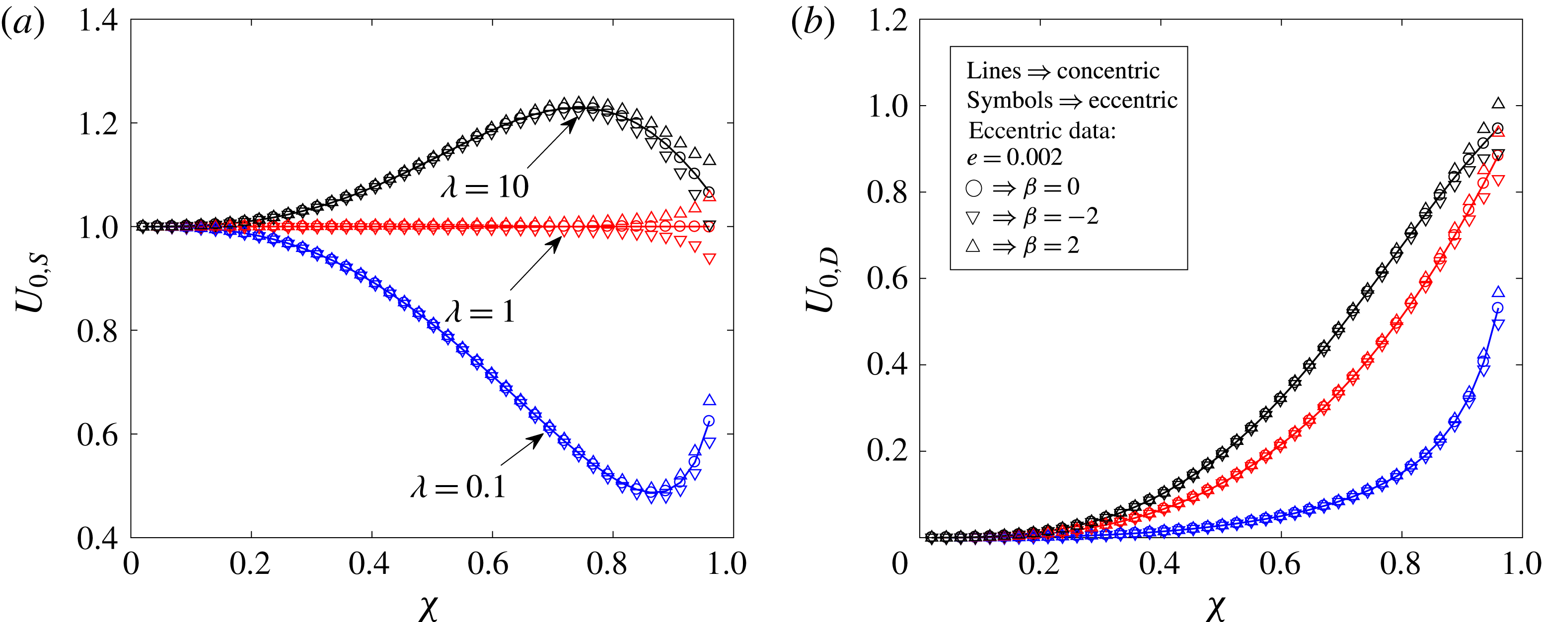
Figure 14. The velocities of (a) a two-mode squirmer
![]() $(U_{0,S})$
and (b) a drop
$(U_{0,S})$
and (b) a drop
![]() $(U_{0,D})$
at
$(U_{0,D})$
at
![]() $O(1)$
plotted as a function of the size ratio for various values of the viscosity ratio. The lines denote the results obtained for the concentric configuration while the symbols indicate the results for an eccentric configuration with an eccentricity of
$O(1)$
plotted as a function of the size ratio for various values of the viscosity ratio. The lines denote the results obtained for the concentric configuration while the symbols indicate the results for an eccentric configuration with an eccentricity of
![]() $e=0.002$
. The symbols ○, ▿ and ▵ are used to denote the results for a neutral swimmer
$e=0.002$
. The symbols ○, ▿ and ▵ are used to denote the results for a neutral swimmer
![]() $(\unicode[STIX]{x1D6FD}=0)$
, a pusher
$(\unicode[STIX]{x1D6FD}=0)$
, a pusher
![]() $(\unicode[STIX]{x1D6FD}=-2)$
and a puller
$(\unicode[STIX]{x1D6FD}=-2)$
and a puller
![]() $(\unicode[STIX]{x1D6FD}=2)$
respectively. All of the velocities are non-dimensionalized using
$(\unicode[STIX]{x1D6FD}=2)$
respectively. All of the velocities are non-dimensionalized using
![]() $U_{sq}=2B_{1}/3$
.
$U_{sq}=2B_{1}/3$
.
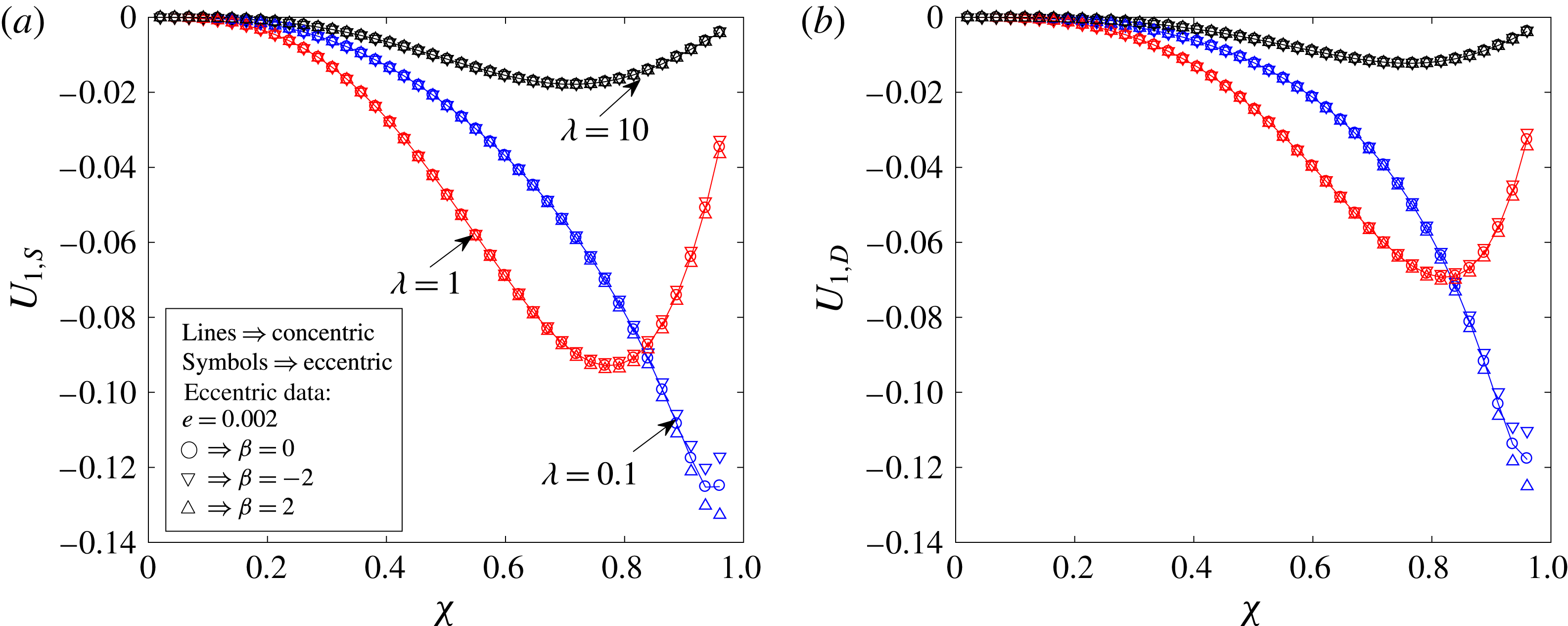
Figure 15. The velocities of (a) a two-mode squirmer
![]() $(U_{1,S})$
and (b) a drop
$(U_{1,S})$
and (b) a drop
![]() $(U_{1,D})$
at
$(U_{1,D})$
at
![]() $O(Pe_{s})$
plotted as a function of the size ratio for various values of the viscosity ratio. Here, we choose
$O(Pe_{s})$
plotted as a function of the size ratio for various values of the viscosity ratio. Here, we choose
![]() $Ma=1$
. The lines denote the results obtained for the concentric configuration while the symbols indicate the results for an eccentric configuration with an eccentricity of
$Ma=1$
. The lines denote the results obtained for the concentric configuration while the symbols indicate the results for an eccentric configuration with an eccentricity of
![]() $e=0.002$
. The symbols ○, ▿ and ▵ are used to denote the results for a neutral swimmer
$e=0.002$
. The symbols ○, ▿ and ▵ are used to denote the results for a neutral swimmer
![]() $(\unicode[STIX]{x1D6FD}=0)$
, a pusher
$(\unicode[STIX]{x1D6FD}=0)$
, a pusher
![]() $(\unicode[STIX]{x1D6FD}=-2)$
and a puller
$(\unicode[STIX]{x1D6FD}=-2)$
and a puller
![]() $(\unicode[STIX]{x1D6FD}=2)$
respectively. All of the velocities are non-dimensionalized using
$(\unicode[STIX]{x1D6FD}=2)$
respectively. All of the velocities are non-dimensionalized using
![]() $U_{sq}=2B_{1}/3$
.
$U_{sq}=2B_{1}/3$
.


