


1. Introduction
The detachment or removal of fine particles from a rough surface can often be found in process engineering, pharmaceutics or environmental engineering. Most existing studies focused on the detachment of particles from rough surfaces equipped with different types of convex roughness structures. However, few studies point to a surface with concave roughness, usually found on mechanically treated surfaces. For example, active pharmaceutical ingredient (API) particles (in the size range of 1–5  $\mathrm {\mu }$m) used for dry powder inhalers are very cohesive and are therefore usually coated on the surface of large carrier particles (with a diameter of 100–500
  $\mathrm {\mu }$m) (Zellnitz et al. Reference Zellnitz, Zellnitz, Müller, Meindl, Schröttner and Fröhlich2019). The carrier surfaces are modified by mechanical treatment (i.e. the carrier particles are usually treated in a ball mill using different grinding materials) in order to adjust the adhesive force between the carrier and the APIs (Cui et al. Reference Cui, Schmalfuß, Zellnitz, Sommerfeld and Urbanetz2014). After grinding, as shown in figure 2 of Renner et al. (Reference Renner, Steckel, Urbanetz and Scherließ2017), the carrier surface has concave roughness structures in the shape of hollow hemispheres. Since the carrier size is much larger than the fine drug particles/APIs, the detachment of the drug particles from the carrier surface is equivalent to the detachment of drug particles from a surface with concave roughness structures. In order to achieve the high drug delivery efficiency of a dry powder inhaler (DPI), it is necessary to construct models of drug particle detachment from the surface with concave roughness in a micro-scale simulation and then implement them into the Lagrangian particle tracking optimising the design of a DPI by using macro-scale simulations.
The surface roughness modifies the energy barrier and the resulting adhesive forces between the particle and the wall. It is important to characterise the surface roughness by analysing the representation of roughness structures in modelling approaches. There are two categories: micro-scale and large-scale roughness structures. Surface modification using chemical treatment usually generates micro-scale roughness structures, while the roughness structures induced by mechanical treatment are usually in a size comparable to the particle size, i.e. large-scale roughness. In micro-scale roughness, hydrodynamic force and torque acting on the particle do not change significantly compared with a particle attached to a smooth surface, as only the surface energy and the resulting adhesive force are reduced by the micro-scale surface roughness structures. In the case of large-scale roughness structures, most available research focuses on the convex roughness structures (Henry & Minier Reference Henry and Minier2014; Xiao et al. Reference Xiao, Luo, Niu, Wang, Wu, Liu and Xu2019). In Ziskind, Fichman & Gutfinger (Reference Ziskind, Fichman and Gutfinger1997) and Henry et al. (Reference Henry, Minier, Lefevre and Hurisse2011) hemisphere asperities are used to represent the roughness structures. The particle in contact with two or three asperities was analytically studied by Ziskind et al. (Reference Ziskind, Fichman and Gutfinger1997). They found that the supporting asperities reduced the detaching moment due to a lower adhesive force and smaller contact radius. In Nasr et al. (Reference Nasr, Ahmadi, Ferro and Dhaniyala2019) the substrate roughness was described using a two-dimensional (2-D) sinusoidal profile. They found that the wavelength and amplitude of roughness structures had played an important role in the critical shear velocity. Cui & Sommerfeld (Reference Cui and Sommerfeld2022) described the 2-D surface roughness as regularly spaced semi-cylindrical asperities on a smooth surface, and the influence of asperity distance and size ratio on particle detachment was studied. Reeks & Hall (Reference Reeks and Hall2001) considered the resuspension of a particle resulting from the oscillation of particles around a pivot point. In their work, the 2-D roughness was described as a two-point asperity contact, while these two points have different altitudes. In conclusion, most studies focused on 2-D roughness, but hemisphere asperities usually represent a three-dimensional (3-D) roughness because fewer parameters are required to characterise the roughness. Therefore, we further choose the advantage of hemisphere asperities representing the roughness structures, and the 3-D concave roughness is described as regularly spaced hollow hemispheres below a smooth surface, as shown in figure 1. The particle always sits on a single hollow hemisphere to reach a mechanically stable condition. Therefore, there are only two dimensionless parameters to describe the concave roughness, i.e. the asperity size ratio  $D_a/D_p$ (asperity diameter
  $D_a$ to particle diameter
  $D_p$) and the dimensionless asperity distance
  $L/D_p$ (the distance between two hollow hemispheres
  $L$ divided by the particle diameter).

Figure 1. A schematic diagram of a spherical particle sitting on a hollow hemisphere with all relevant dimensions.
The hydrodynamic force and torque acting on the particle must be correctly determined to analyse the particle detachment. The drag coefficient acting on a sphere attached to a flat surface in a linear shear flow was analytically derived by O'Neill (Reference O'Neill1968) in the Stokes regime. At a finite particle Reynolds number (i.e.  $Re_p$), a semi-empirical drag correlation was proposed by Schiller & Naumann (Reference Schiller and Naumann1933) for particles in unconfined flow. The drag correlation from the combination of O'Neill (Reference O'Neill1968) and Schiller & Naumann (Reference Schiller and Naumann1933) is generally accepted for calculating the drag coefficient of a particle on a smooth surface at a finite particle Reynolds number (Cui & Sommerfeld Reference Cui and Sommerfeld2015; Nasr et al. Reference Nasr, Ahmadi, Ferro and Dhaniyala2019). At
  $Re_p>1000$, the flow around the particle is fully turbulent, and the drag coefficient of the particle depends on the particle size compared with the height of the turbulent boundary layer (Sommerfeld, van Wachem & Oliemans Reference Sommerfeld, van Wachem and Oliemans2008). In the case of a particle attached to a wall, the lift coefficient of the particle gives a constant value of
  $5.87$ in the Stokes regime (Leighton & Acrivos Reference Leighton and Acrivos1985) and has a trend of the power law decreasing at finite Reynolds number (Zeng et al. Reference Zeng, Najjar, Balachandar and Fischer2009). The torque coefficient is usually represented by the drag force acting on the upper surface of the particle, i.e.
  $M_h=c_M\, F_D\, R_p$ (where
  $M_h$,
  $F_D$ are the hydrodynamic torque and the drag force acting on the particle, respectively;
  $c_M$,
  $R_p$ are the torque coefficient and the particle radius, respectively). Goldman's analytical solution yields
  $c_M=0.37$. A recent study by Cui & Sommerfeld (Reference Cui and Sommerfeld2022) shows that the torque coefficient is not a constant value at a finite particle Reynolds number. The value of the torque coefficient approaches Goldman's analytical solution in the Stokes regime and decreases significantly with increasing
  $Re_p$. However, most relevant studies used
  $c_M=0.37$ for all ranges of
  $Re_p$. Therefore, the calculation of hydrodynamic torque may be insufficiently accurate. One solution is to construct a torque coefficient model by using direct numerical simulation (DNS) results. In conclusion, there are various correlations of hydrodynamic force and torque in the case of a particle attached to a flat wall. However, in the case of a particle sitting on a hollow hemisphere, there are no available models in the literature. The asperity size ratio could significantly influence hydrodynamic force and torque on the particle since the particle's bottom surface is covered by the hollow hemisphere. Therefore, the current study calculates the hydrodynamic force and torque on the particle by performing lattice Boltzmann (LB) simulations.
In addition to the asperity size ratio, the distance between asperities and the distribution of asperities has a considerable influence on the hydrodynamic force and torque acting on the particle. Cui & Sommerfeld (Reference Cui and Sommerfeld2022) found that with increasing asperity distance, the drag and lift coefficients increase while the torque coefficient decreases. Their particle was positioned on two semi-cylindrical asperities; therefore, the particle height was closely related to the asperity distance. In Ziskind et al. (Reference Ziskind, Fichman and Gutfinger1997) two types of distributions of asperities were considered. They found that the distribution of three hemispheres could change the fluid stress distribution around the particle. In this work, the particle is attached to a single hollow hemisphere. Its height therefore remains unchanged at a fixed asperity size ratio. In Stokes flow the flow can smoothly pass through the upper surface of the hollow hemisphere, and, therefore, the influence of the distribution of roughness asperities on the flow field around the particle may be neglected. However, it remains an open question whether or not the distribution of asperities has a considerable influence on the hydrodynamic force and torque on the particle at a finite particle Reynolds number.
Particles can detach from a surface through three mechanisms: lifting, sliding or rolling. For micron-sized particles, the hydrodynamic lift force is usually much smaller than the adhesive force between the particle and the wall and, therefore, the occurrence of a lifting detachment is difficult. One exception is when the particle experiences a turbulent flow with high turbulent intensities. Cui & Sommerfeld (Reference Cui and Sommerfeld2017) found that some API particles can lift from the carrier surface at turbulent intensity  $I=9\,\%$. In the case of a particle attached to a flat wall, the sliding detachment is more effortless than the rolling detachment (Cui & Sommerfeld Reference Cui and Sommerfeld2015). The reason is that the torque arm of the adhesive force is the contact radius, which is related to the surface energy of the surface and is very small compared with the particle size. Therefore, the rolling resistance is weaker than the sliding resistance induced by the friction force. In the case of a particle attached to a surface with convex roughness, the torque arm of the adhesive force increases significantly. Cui & Sommerfeld (Reference Cui and Sommerfeld2022) found that the sliding detachment is more likely to occur than the rolling detachment. However, compared with the study of convex roughness (Cui & Sommerfeld Reference Cui and Sommerfeld2022), the torque arm of the adhesive force becomes smaller in the case of a particle attached to a surface with concave roughness. Under such conditions, it remains unknown which detachment mechanism tends to occur first.
This work focuses on the detachment of micro-sized particles from a surface with concave roughness. The roughness is described as regularly spaced hollow hemispheres below a smooth surface. The hydrodynamic force and torque acting on the particle are calculated by performing LB simulations. A short introduction of the lattice Boltzmann method (LBM) including the methodologies to improve the computational efficiency and accuracy is given in § 2. Set-ups of LB simulations and numerical validations are also presented in § 2. In § 3 empirical correlations of the drag, lift and torque coefficients are proposed for a particle attached to a surface with concave roughness. In § 4 detachment models are proposed for a particle attached to a surface with concave roughness, and the influence of the asperity size ratio and dimensionless asperity distance on particle detachment is analysed. Moreover, the numerical solutions of the critical particle Reynolds number (above which the detachment of the particle occurs) as a function of the asperity size ratio and dimensionless adhesion force are proposed for the lifting, sliding and rolling detachment. Also, the detachment mechanism which occurs first is studied. The current work not only fills the research gap for particles detached from surfaces with concave roughness, the proposed correlations can also be used to determine the hydrodynamic force and torque on a particle embedded in a flat surface.
2. Set-up of the LB simulation
2.1. Brief introduction of the LBM
The LBM is a computational fluid dynamics method based on a mesoscopic model. Adeeper understanding of physical phenomena and more detailed modelling are attributed to its direct connection with gas dynamics theory. The LBM avoids the huge number of grid elements required for solving complex geometries of obstacles. In this work the discrete LB equation combined with a multi-relaxation time collision operator is being solved, i.e.
 \begin{equation} f_i(\boldsymbol x+\boldsymbol{e_i}\, {{\rm d}}t, t+{{\rm d}}t) = f_i(\boldsymbol x, t)+\varOmega_i^{{MRT}}(f_1,\ldots,f_b), \quad i=1,\ldots, b, \end{equation}
where  $f_i(\boldsymbol r, t)$ is the probability distribution function (PDF) and a function of the position
  $\boldsymbol x$ and the time
  $t$;
$t$;  $\boldsymbol {e_i}$,
  $\varOmega _i^{{MRT}}$ are the fluid velocity and the multi-relaxation time collision operator that computes a post-collision state conserving mass and linear momentum (D'Humieres Reference D'Humieres1994). The D3Q27 model is applied (i.e. a 3-D model where each node involves 27 velocity vectors) and, therefore,
  $b=27$. The macroscopic variables can be derived from the statistical moment of the PDFs, i.e.
 \begin{equation} \rho=\sum_{i=1}^{b}f_i, \quad \rho \boldsymbol u=\sum_{i=1}^{b}f_i\boldsymbol{e_i}. \end{equation}
The zero-order moment corresponds to the macroscopic density, and the first-order moment provides momentum in three directions. Using second-order boundary conditions instead of first-order boundary conditions can improve the accuracy of the LB simulation results but can reduce the computation efficiency. In this study, a second-order boundary condition for calculating the force and torque on the particle is applied.
The curved particle surface can be accurately explained by using the curved wall boundary condition (Guo, Zheng & Shi Reference Guo, Zheng and Shi2002). The local grid refinement method is applied to save the calculation time, i.e. discretization of the fluid region around the particle using fine grid elements and discretization of the outer flow region without a strong velocity gradient using the coarse grid. Each level of mesh refinement reduces the grid size precisely twice (Bouzidi, Firdaouss & Lallemand Reference Bouzidi, Firdaouss and Lallemand2001). In addition, a buffer zone is applied between the two adjustment levels to reduce the discontinuity between the refinement levels. In this work, the length of the buffer is two grid elements (Li & Zhong Reference Li and Zhong2016). If the particle Reynolds number  $Re_p\geq 10$, the wake developing near the rear end of the particle is further refined to improve the numerical accuracy, as shown in figure 6.
2.2. Characterisation of concave roughness
As mentioned above, concave roughness structures are described as regularly spaced hollow hemispheres below a smooth surface. Two dimensionless parameters are introduced to characterise the concave roughness, namely the dimensionless asperity distance  $L/D_p$ and the asperity size ratio
  $D_a/D_p$ (see figure 1). The particle Reynolds number is defined in terms of the shear rate
  $G$ and particle diameter as
 \begin{equation} Re_p=\frac{GD_p^{2}}{2\nu}, \end{equation}
where  $\nu$ is the fluid kinematic viscosity. The particle Reynolds number remains the same by varying the asperity size ratio, and, therefore, it is possible to gain more insight into the physical interpretation of the results, e.g. to understand how much the drag, lift and torque coefficients change as the particle sits deeper in a larger hole. As shown in figure 1, the height of the particle centroid
  $H=0.5D_p\cos \alpha$ (where
  $\alpha$ is the contact angle). The particle height
  $H$ decreases with increasing asperity size ratios as the particle is more embedded in the supporting hollow hemisphere.
In this work two types of distributions of hollow hemispheres on the surface are considered, as shown in figure 2. In case  $A$ the adjacent asperities having the closest distance are distributed in lines in the streamwise direction. The difference between the two cases is that case
  $B$ results from the rotation of case
  $A$ around the vertical direction of the fluid domain by 45
 $^{\circ }$. In both cases, the asperity distance and size are the same.

Figure 2. Particle deposited on two different types of hollow hemisphere distributions; case  $A$: adjacent asperities having the closest distance are distributed in lines in the streamwise direction; case
  $B$: adjacent asperities having the largest distance are distributed in lines in the streamwise direction; case
  $B$ is the rotation of case
  $A$ around the vertical direction by 45
 $^{\circ }$ (
 $D_a/D_p=0.5$,
  $L/D_p=1$).
2.3. Boundary conditions and dimensions
In the simulation the particle is fixed in a rectangular computational domain, as shown in figure 3. The rough wall is assigned as a non-slip boundary condition. Two sidewalls are assigned as the symmetric boundary condition. A linear shear flow is imposed at the inlet. At the outlet, a zero gradient condition in the direction perpendicular to the outlet plane is applied, enforcing all velocities at the outlet to remain constant in the streamwise direction.

Figure 3. Computational domain with applied boundary conditions for the simulations and the relevant coordinate system.
The proper selection of dimensions of the computational domain for optimising accuracy and computational effort is based on an extensive parameter study. For each case, the particle is resolved by 80 grids cells of the finest mesh per particle diameter, which was verified to be sufficient (Cui & Sommerfeld Reference Cui and Sommerfeld2022). At the beginning of the verification, the domain sizes are  $x/D_p=y/D_p=z/D_p=5$, where
  $x$,
$x$,  $y$,
$y$,  $z$ refer to the streamwise direction, the vertical direction and the lateral direction, respectively. To verify the required domain size, three dimensions of the fluid domain are increased simultaneously. The forces over a particle are computed from the momentum exchange at the fixed solid surface of the particle. The drag and lift coefficients of the particle are a function of dimension and are defined as
 \begin{equation} c_D=\frac{F_D}{\dfrac{\rho_f}{2}\left[{\dfrac{GD_p}{2}} \right]^{2}\dfrac{\rm \pi}{4}D_p^{2}}, \quad c_L=\frac{F_L}{\dfrac{\rho_f}{2} \left[{\dfrac{GD_p}{2}}\right]^{2}\dfrac{\rm \pi}{4}D_p^{2}}, \end{equation}
where  $\rho _f$ is the fluid density and
  $F_L$ is the hydrodynamic lift force acting on the particle. The torque coefficient is defined as
 \begin{equation} c_M=\frac{M_h}{F_D\, R_p}[1+0.15Re_p^{0.687}]. \end{equation}
 As illustrated in figure 4, the drag, lift and torque coefficients reach constant values with increasing dimensions in the case of a particle attached to a smooth wall. It revealed that the dimensions of  $x/D_p=y/D_p=z/D_p=20$ are sufficient to obtain drag, lift and torque coefficients that are independent of the dimension. In the case of the rough wall, as illustrated in figure 5, the drag, lift and torque coefficients reach constant values at the domain size of
  $x/D_p=y/D_p=z/D_p=20$ as well. The total number of grid elements used in this study is about 10.9 million. The generated mesh of the computational domain is plotted in figure 6. The grid refinement around the particle, as well as the wake refinement downstream the rear end of the particle for
  $Re_p\geq 10$, are shown in the figure.

Figure 4. Simulated drag, lift and torque coefficients for the particle attached to a smooth wall with increasing domain size; initial domain size:  $x/D_p=5$,
  $y/D_p=5$,
  $z/D_p=5$; three dimensions of the fluid domain are increased simultaneously; domain size normalised by particle diameter
  $D_p$; (a) drag coefficient; (b) lift coefficient; (c) torque coefficient (
 $Re_p=0.02$; resolution: 80 grid cells of the finest mesh per particle diameter with three levels of grid refinement).

Figure 5. Simulated drag, lift and torque coefficients for the particle in contact with a single hollow hemisphere with increasing domain size; initial domain size:  $x/D_p=5$,
  $y/D_p=5$,
  $z/D_p=5$; three dimensions of the fluid domain are increased simultaneously; domain size normalised by particle diameter
  $D_p$; (a) drag coefficient; (b) lift coefficient; (c) torque coefficient (
 $Re_p=0.02$;
  $D_a/D_p=0.5$;
  $L/D_p = 1$; resolution: 80 grid cells of the finest mesh per particle diameter with three levels of grid refinement).

Figure 6. Mesh of the fluid domain for the conducted simulations; resolution: 80 grid cells of the finest mesh per particle diameter with three levels of grid refinement; domain size:  $x/D_p=y/D_p=z/D_p=20$; the total number of grid elements is about 10.9 million.
2.4. Numerical validation
In order to ensure the calculation accuracy of the LB simulation, the current LB simulation results are validated by comparing them with analytical or semi-empirical correlations in the case of a particle attached to a smooth wall.
First, the drag, lift and torque coefficients as a function of  $Re_p$ in the case of a particle attached to a flat surface are plotted in figure 7. In the Stokes regime, Goldman's analytical solution provides a value of
  $c_M=0.37$ (Goldman, Cox & Brenner Reference Goldman, Cox and Brenner1967). The analytical solution of the drag coefficient of a particle attached to a smooth wall was given by Goldman et al. (Reference Goldman, Cox and Brenner1967) and O'Neill (Reference O'Neill1968),
 \begin{equation} c_{D}=1.7009\frac{24}{Re_p}. \end{equation}
Figure 7. Simulated drag, lift and torque coefficients of a particle attached to a flat surface as a function of particle Reynolds number; (a) the simulated drag coefficients are compared with O'Neill (Reference O'Neill1968) analytical solution ((2.6)), the universal correlation ((2.8)) and the DNS results (Zeng et al. Reference Zeng, Najjar, Balachandar and Fischer2009; Lee & Balachandar Reference Lee and Balachandar2010); (b) the simulated lift coefficients are compared with the analytical solution of lift coefficient in the Stokes flow (Leighton & Acrivos Reference Leighton and Acrivos1985) and the DNS results (Zeng et al. Reference Zeng, Najjar, Balachandar and Fischer2009); (c) the simulated torque coefficients are compared with Goldman's analytical solution (Goldman et al. Reference Goldman, Cox and Brenner1967).
A frequently used semi-empirical correlation of drag coefficient of a particle in unconfined flow was proposed by Schiller & Naumann (Reference Schiller and Naumann1933):
 \begin{equation} c_{D}=\frac{24}{Re_p}[1+0.15Re_p^{0.687}] \quad \text{for } Re_p<1000. \end{equation}
A universal correlation based on the drag models of (2.6) and (2.7) is often used (Zeng et al. Reference Zeng, Najjar, Balachandar and Fischer2009; Cui & Sommerfeld Reference Cui and Sommerfeld2015):
 \begin{equation} c_{D}=1.7009\frac{24}{Re_p}[1+0.15Re_p^{0.687}] \quad \text{for } Re_p<1000. \end{equation}
 The current simulation results of the drag coefficient show a good agreement with O'Neil's analytical solution at small particle Reynolds numbers, but the difference between the two results becomes evident at  $Re_p>1$. With larger
  $Re_p$, the present results of the drag coefficient are in good agreement with the results of the correlated model of O'Neil ((2.8)) and the DNS results (Zeng et al. Reference Zeng, Najjar, Balachandar and Fischer2009; Lee & Balachandar Reference Lee and Balachandar2010), proving the validity of the current LB simulation. The calculated lift coefficient approaches the analytical solution of Leighton & Acrivos (Reference Leighton and Acrivos1985) in the Stokes flow regime, i.e.
  $c_L=5.87$. At finite
  $Re_p$, the present LB simulation results agree very well with the DNS results of Zeng et al. (Reference Zeng, Najjar, Balachandar and Fischer2009). The LB simulation results are again validated by comparing the calculated torque coefficient with Goldman's analytical solution. As the particle Reynolds number decreases, the LB simulation result approaches the analytical solution of Goldman (i.e.
  $c_M=0.37$), which is indicated on the horizontal line in figure 7(c). At
  $Re_p=0.02$, the difference in values between the current results and Goldman's analytical solution is only 1.85 %.
3. Hydrodynamic force and torque acting on the particle
This section begins with an analysis of the influence of the dimensionless asperity distance and the distribution of asperities on the drag, lift and torque coefficients of the particle. After that, the influence of different asperity size ratios on the particle forces is studied. Finally, based on the LB simulation results, empirical correlations of drag, lift and torque coefficients of a spherical particle attached to a surface with concave roughness are proposed.
Figure 8 summarises the drag, lift and torque coefficients of the particle at a fixed asperity size ratio  $D_a/D_p=0.5$ for two different dimensionless asperity distances. In the following, the drag coefficient is plotted by multiplying
  $Re_p$ to prevent the vertical axis from ranging over several orders of magnitude, and therefore interesting details could become more apparent. The difference between the two groups of results is very small. The maximum differences in values of drag, lift and torque coefficients between these results are 0.55 %, 0.91 % and 1.97 %, respectively, for particle Reynolds numbers ranging from 0.01 to 40. It should be noted that the torque coefficient is defined in terms of
  $[1+0.15Re_p^{0.687}]$ to prevent viscous scaling, and, therefore, the difference in results is larger than the case of drag and lift coefficients. Figure 9 plots the flow field and streamlines around the particle and the adjacent asperities for different dimensionless asperity distances. The dimensionless streamwise flow velocity is defined as
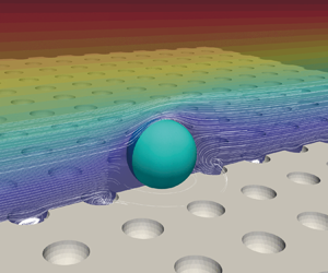
  $U_x^{*}=2U_x/[GD_p]$. Swirling flow develops inside the hollow hemisphere. However, in these two cases, there is no obvious difference in the distribution of streamlines and the magnitudes of flow velocities. Figure 10 plots the velocity profiles of the line
  $A$, as shown in figure 9 (
 $L_{line}/D_p=0.75$, where
  $L_{line}$ is the distance between the line and the particle centroid in the streamwise direction), for two different dimensionless asperity distances. The slight difference in flow velocities for the two different
  $L/D_p$ values indicates that there are only minor changes to the velocity distribution around the particle as the dimensionless asperity distance varies. Therefore, it is reasonable to neglect the influence of dimensionless asperity distance on the analysis of the hydrodynamic force and torque on the particle.

Figure 8. Simulated drag, lift and torque coefficients of a particle attached to a rough surface with regularly spaced hollow hemispheres as a function of the particle Reynolds number for two different dimensionless asperity distances  $L/D_p = 1$ or
  $1.5$; (a) drag coefficient
  $c_D$; (b) lift coefficient
  $c_L$; (c) torque coefficient
  $c_M$ (
 $D_a/D_p=0.5$).

Figure 9. Particle deposited on a rough surface with regularly spaced hollow hemispheres; coloured contours of the dimensionless streamwise flow velocity in the vertical middle plane of the domain; (a) dimensionless asperity distance  $L/D_p = 1$; (b)
  $L/D_p =1.5$ (
 $D_a/D_p=0.5$,
  $Re_p=20$).

Figure 10. Velocity profiles along line  $A$, as depicted in figure 9, for different dimensionless asperity distances; (a) flow velocity in the streamwise direction
  $U_x$; (b) flow velocity in the vertical direction
  $U_y$; the straight dash-dotted line indicates the height of the upper surface of the particle
  $H+0.5D_p=0.93D_p$ (
 $D_a/D_p=0.5$).
Different types of asperity distributions are also considered in this study, i.e. case  $A$ and case
  $B$ as shown in figure 2, and their influence on the drag, lift and torque coefficients are compared in figure 11. Case
  $B$ is the rotation of case
  $A$ around the vertical axis of 45
 $^{\circ }$. In the case of Stokes flow or flow at finite
  $Re_p$, the differences in values between the two cases are both very small. Therefore, it is only necessary to consider the influence of the asperity size ratio on the hydrodynamic force and torque. The dimension of the concave roughness problem is reduced to one.

Figure 11. Simulated drag, lift and torque coefficients of a particle attached to a rough surface with regularly spaced hollow hemispheres as a function of the asperity size ratio for two types of asperity distributions (cases  $A$ and
  $B$, as depicted in figure 2); (a) drag coefficient
  $c_D$; (b) lift coefficient
  $c_L$; (c) torque coefficient
  $c_M$ (
 $D_a/D_p=0.5$,
  $L/D_p=1$).
Figure 12 plots the drag, lift and torque coefficients as a function of the particle Reynolds number for asperity size ratios  $D_a/D_p$ ranging from 0 to 0.9. Here
  $D_a/D_p=0$ indicates the case of a particle attached to a flat surface. The drag and lift coefficients decrease with increasing asperity size ratios. The reason is that with increasing asperity size ratio
  $D_a/D_p$, the height of the particle centroid
  $H$ decreases as the particle is more embedded in the hollow hemisphere. Therefore, the fluid stress around the particle becomes smaller at larger asperity size ratios. As illustrated in figure 13, at the same particle Reynolds number, the distance between the line of
  $U_x^{*}=1$ (i.e. the dimensionless streamwise flow velocity) and the particle's upper layer increases at a larger asperity size ratio, and, therefore, the particle encounters a smaller hydrodynamic force. In order to avoid viscous scaling, the torque coefficient is defined in terms of
  $[1+0.15Re_p^{0.687}]$ and the drag coefficient is plotted by multiplying the particle Reynolds number. Both the drag and torque coefficients increase with increasing
  $Re_p$ since the inertia effect of the fluid plays a more important role at finite
  $Re_p$.

Figure 12. Simulated drag, lift and torque coefficients of a particle attached to a rough surface with regularly spaced hollow hemispheres as a function of the particle Reynolds number for different asperity size ratios; (a) drag coefficient  $c_D$; (b) lift coefficient
  $c_L$; (c) torque coefficient
  $c_M$ (
 $L/D_p=1$).

Figure 13. Particle deposited on a rough surface with regularly spaced hollow hemispheres for different particle Reynolds numbers and asperity size ratios, coloured contours of the dimensionless streamwise flow velocity in the vertical middle plane of the domain; left column:  $D_a/D_p = 0.5$; right column:
  $D_a/D_p =0.9$ (
 $L/D_p=1$).
As the asperity distance and distribution of asperities have a neglectable influence on the velocity distribution around the particle, the hydrodynamic force and torque are as a function of the particle Reynolds number  $Re_p$ and the asperity size ratio
  $D_a/D_p$. The correlations of drag, lift and torque coefficients are proposed as
 \begin{equation} \left.\begin{array}{c} c_D(Re_p)=\dfrac{1}{Re_p}[a_1+b_1 Re_p^{c_1}], \\ c_L(Re_p)=\dfrac{a_2}{[Re_p^{b_2}+c_2]^{d_2}}, \\ c_M(Re_p)=a_3+b_3Re_p^{c_3}, \end{array}\right\} \end{equation}
where  $a_1$,
  $b_1$,
  $c_1$,
  $a_2$,
  $b_2$,
  $c_2$,
  $d_2$,
  $a_3$,
  $b_3$,
  $c_3$ are coefficients and are functions of the asperity size ratio
  $D_a/D_p$. Their correlations are given by
 \begin{align} \left.\begin{array}{c} \left[\begin{array}{c} a_1(D_a/D_p) \\ b_1(D_a/D_p) \\ c_1(D_a/D_p) \\ a_3(D_a/D_p) \\ b_3(D_a/D_p) \\ c_3(D_a/D_p) \end{array} \right]=\left[\begin{array}{cccc} 38.502 & 3.969 & -18.791 & 0 \\ 6.500 & 0.044 & -4.257 & 0 \\ 0.717 & 0.024 & -0.041 & 0 \\ 0.345 & -0.026 & 0.134 & 0.020 \\ 0.058 & 0.009 & -0.066 & 0.077 \\ 0.291 & -0.185 & 0.907 & -0.515 \\ \end{array} \right] \left[\begin{array}{c} 1 \\ D_a/D_p \\ {[}D_a/D_p]^{2} \\ {[}D_a/D_p]^{3} \end{array} \right], \\ a_2(D_a/D_p)=3.601-1.271[D_a/D_p]^{3.455}, \\ b_2(D_a/D_p)=2.103+2.198[D_a/D_p]^{4.428}, \\ c_2(D_a/D_p)=0.105+0.209[D_a/D_p]^{5.503}, \\ d_2(D_a/D_p)=0.206-0.106[D_a/D_p]^{2.693}. \end{array}\right\} \end{align}
The lines connecting symbols in figure 12 are the proposed correlations. The drag, lift and torque coefficients as functions of the asperity size ratio are further plotted in figure 14 for three different particle Reynolds numbers. The lines connecting the plotted data are the correlations of (3.1) and (3.2). A good agreement between the data and the correlating line proves that the proposed correlations of drag, lift and torque coefficients maintain good accuracy at a fixed particle Reynolds number by varying the asperity ratio. The proposed correlations are valuable for analysing particle detachment from a surface with concave roughness.

Figure 14. Simulated drag, lift and torque coefficients of a particle attached to a rough surface with regularly spaced hollow hemispheres as a function of the asperity size ratio for different particle Reynolds numbers; (a) drag coefficient  $c_D$; (b) lift coefficient
  $c_L$; (c) torque coefficient
  $c_M$ (
 $L/D_p=1$).
4. Particle detachment study
The particle can be detached from the surface through lifting, sliding and rolling. The studies of particle detachment usually focus on micron-sized particles because the adhesive force between the particle and the wall plays an important role in particle detachment. As shown in figure 15, the contact region between the particle and the hollow hemisphere is ring shaped. The adhesive force therefore contains many force components acting in the annular region, and each component of the adhesive force is in the direction of the line connecting the contact point and the particle centroid. The resulting force of adhesion acts in the opposite direction of the normal surface vector.

Figure 15. Illustration of the resultant adhesive force acting on the particle attached to a hollow hemisphere.
The geometry of the contact has a large influence on determining the adhesive force. In this study the contact between the particle and the asperity occurs along a circle, and the resultant adhesive force is normal to the surface. However, in some cases, the contact points between the particle and the rough wall may have different altitudes, therefore, the detachment of the particle results from the oscillation of particles around a pivot point (Henry & Minier Reference Henry and Minier2014). In such a condition, the detachment of a particle is no more a force balance but requires a damped oscillator model, which is referred to as the ‘Rock’n‘Roll’ model (Reeks & Hall Reference Reeks and Hall2001). If the contact points have the same altitude but have different contact geometries, the adhesion force can be accurately estimated by using the surface element integration method (Bhattacharjee, Ko & Elimelech Reference Bhattacharjee, Ko and Elimelech1998), which has the advantage of being applied to any geometry.
In this work the adhesive force is measured using atomic force microscopy (AFM) for API particles attached to the carrier surface modified by different surface treatment methods. The adhesive force can also be calculated based on the surface energy and material properties using Johnson–Kendall–Roberts or Derjaguin–Muller–Toporov theories (Johnson, Kendall & Roberts Reference Johnson, Kendall and Roberts1971; Derjaguin, Muller & Toporov Reference Derjaguin, Muller and Toporov1975). The value of adhesive force considered in this study ranges from  $50$ nN to
  $300$ nN, which covers the range of values of the measured adhesion force of APIs by using AFM (Cui et al. Reference Cui, Schmalfuß, Zellnitz, Sommerfeld and Urbanetz2014). Moreover, we introduce the dimensionless adhesion force as
 \begin{equation} F_{ad}^{*}=\frac{F_{ad}}{D_p^{2}\mu G}, \end{equation}
where  $\mu$ is the fluid viscosity. It should be noted that the dimensionless adhesion force is defined in terms of the shear rate. Therefore, at a constant value of adhesion force, the corresponding dimensionless adhesion force varies with the particle Reynolds number. In this work the dimensionless adhesion force is between
  $0.23$ and
  $27\ 323$ for
  $Re_p=0.02$ to
  $40$. The friction coefficient of the carrier glass beads is calculated from the measured wall friction angles, and its value is 0.111. The fluid is air with a density of
  $1.2074\ \textrm {kg}\ \textrm {m}^{-3}$ and a kinematic viscosity of
  $1.51\times 10^{-5}\ \textrm {m}^{2}\ \textrm {s}^{-1}$.
The gravity of a micron-sized particle is very small compared with the hydrodynamic forces and the adhesive force (Cui & Sommerfeld Reference Cui and Sommerfeld2015, Reference Cui and Sommerfeld2022) and, therefore, is neglected in this study. Subsequently, as shown in figure 1, the lifting detachment is based on a force balance between the hydrodynamic lift force  $F_L$ and the adhesion force
  $F_{ad}$. The sliding and rolling detachment can only occur at the contact point
  $X$ in the downstream location. Sliding detachment at point
  $X$ occurs perpendicular to the line connecting contact point
  $X$ and the particle centroid. If the fluid dynamic forces acting in this direction are larger than the friction force, the particle can detach at point
  $X$ through sliding. The rolling detachment is based on the torque balance around the detachment point
  $X$. The momentums generated by the drag and lift forces around the point
  $X$, as well as the hydrodynamic torque around the particle centroid, must overcome the momentum resistance generated by the adhesive force. The detachment criterion of lifting, sliding and rolling can be expressed as
 \begin{equation} \left.\begin{array}{c@{}} \mbox{Lifting:} \ F_L > F_{ad}, \\ \mbox{Sliding:} \ F_D\cos\alpha + F_L\sin\alpha - F_{ad}\sin\alpha > \mu_w P, \\ \mbox{Rolling:} \ M_h + F_D R_p\cos\alpha + F_L R_a > F_{ad}R_a, \\ \end{array}\right\} \end{equation}
where  $\alpha$,
  $\mu _w$,
  $R_a$ are the contact angle, the friction coefficient between the particle and the wall, and the radius of the asperity, respectively. Here
  $P$ is the total normal load at point
  $X$ and is given by
 \begin{equation} P=F_D\sin\alpha - F_L\cos\alpha + F_{ad}\cos\alpha. \end{equation}
As there is only one particle in this study, the results of particle detachment analysed by (4.2) are merely ‘yes’ or ‘no’. In order to have an insight of the detachment tendency by roughness structures, detachment ratios are defined as the left parts of (4.2) dividing the right parts of the equation, i.e.
 \begin{equation} \left.\begin{array}{c@{}} \text{Lifting ratio:} \ \varphi_{lift} = F_L / F_{ad}, \\ \text{Sliding ratio:} \ \varphi_{slide}=[F_D\cos\alpha + F_L\sin\alpha - F_{ad}\sin\alpha] / \mu_w P, \\ \text{Rolling ratio:} \ \varphi_{roll}=[M_h + F_D R_p\cos\alpha + F_L R_a] / F_{ad}R_a. \\ \end{array}\right\} \end{equation}
If the lifting ratio  $\varphi _{lift}$, the sliding ratio
  $\varphi _{slide}$ and the rolling ratio
  $\varphi _{roll}$ are larger than one, the lifting, sliding and rolling detachment takes place, respectively. The minimum value of the sliding ratio is zero to prevent the left part of (4.2) from having negative values.
At the minimum value of the measured adhesion force, i.e.  $F_{ad}=50$ nN, the lifting ratio becomes the largest. However, as shown in figure 16, the lifting detachment only takes place at large particle Reynolds numbers, i.e.
  $Re_p > 20$. At
  $Re_p=40$, the lifting detachment occurs for the entire range of asperity size ratio. It should be noted that the maximum particle Reynolds number inside a DPI is about
  $10$ (Sommerfeld & Schmalfuß Reference Sommerfeld and Schmalfuß2015). Therefore, the direct lifting detachment of API particles within a DPI is not feasible.

Figure 16. The lifting ratio of the particle detachment as a function of the asperity size ratio for different particle Reynolds numbers ( $L/D_p=1$,
  $F_{ad}=50$ nN).
Further analysis of sliding and rolling detachment probabilities is done as a function of the asperity size ratio  $D_a/D_p$ (see figure 17). The sliding and rolling ratios show a trend of the power law decreasing with increasing asperity size ratios. This is because the particle is more embedded in the hollow hemisphere at a larger asperity size ratio, and, therefore, both the drag and lift forces decrease, making the particle more difficult to detach. At
  $Re_p=0.2$ and
  $0.4$, the sliding detachment will not occur since the hydrodynamic force and torque are too small. The sliding ratio increases with increasing Reynolds numbers. At
  $Re_p=10$, the sliding detachment takes place for a wide range, i.e.
  $D_a/D_p\leq 0.8$. The rolling ratio is larger than the sliding ratio under the same set-up of simulation. At
  $Re_p=10$, the rolling ratio is larger than one even at
  $D_a/D_p=0.9$. At
  $Re_p=4$, the rolling detachment remains possible if
  $D_a/D_p\leq 0.5$. The dimensionless adhesion force is defined in terms of shear rate and is related to the particle Reynolds number. As shown in figure 17, the difficulty in detachment increases with increasing dimensionless adhesion force. Therefore, the dimensionless adhesion force could be one of the reference values for estimating the detachment difficulty.

Figure 17. The sliding (a) and rolling (b) ratios of the particle detachment as a function of the asperity size ratio  $D_a/D_p$ for different particle Reynolds numbers (
 $L/D_p=1$,
  $F_{ad}=50$ nN).
As expected, the detachment probabilities at a larger adhesion force (i.e.  $F_{ad}=300$ nN, the corresponding dimensionless adhesion force
  $F_{ad}^{*}=1366.16$ and
  $54.65$ for
  $Re_p=0.4$ and
  $10$, respectively) are more difficult than with a small value of adhesion force
  $F_{ad}=50$ nN (the corresponding dimensionless adhesion force
  $F_{ad}^{*}=227.69$ and
  $9.11$ for
  $Re_p=0.4$ and
  $10$, respectively); see figure 18. At
  $Re_p=10$, the sliding and rolling detachment occur for a wide range of asperity size ratio values for
  $F_{ad}=50$ nN, whereas the sliding and rolling detachment only occur at small asperity size ratios for
  $F_{ad}=300$ nN.

Figure 18. The sliding (a) and rolling (b) ratios of the particle detachment as a function of the asperity size ratio  $D_a/D_p$ for two different adhesion forces,
  $F_{ad}=50$ nN or
  $300$ nN (
 $L/D_p=1$).
Merely understanding the influence of various parameters on particle detachment is not sufficient for readers to apply the findings to their research work. From the user's point of view, the more important question is: for any given value of the asperity size ratio and the adhesion force, at what value of the particle Reynolds number can the particle detach from the surface with concave roughness? (i.e. how to find the critical particle Reynolds number  $Re_{p,cri}$ as a function of the asperity size ratio
  $D_a/D_p$ and adhesion force
  $F_{ad}$?) Therefore, it is necessary to solve equations of
 \begin{equation} \varphi_{lift}(Re_{p,cri,lift}) = 1, \quad \varphi_{slide}(Re_{p,cri,slide}) = 1\quad \text{and} \quad \varphi_{roll}(Re_{p,cri,roll}) = 1. \end{equation}
 For any given value of asperity size ratio  $D_a/D_p$, the drag
  $c_D$, lift
  $c_L$ and torque
  $c_M$ coefficients are as functions of the particle Reynolds number
  $Re_p$, as illustrated in the proposed correlations of (3.1) and (3.2). Therefore, the drag force
  $F_D$, the lift force
  $F_L$ and the hydrodynamic torque
  $M_h$ in (4.4) are also as functions of the particle Reynolds number
  $Re_p$ (see (2.4a,b) and (2.5)). If the adhesion force
  $F_{ad}$ is known as well, the only unknown parameter in (4.4) and (4.5a–c) is the critical particle Reynolds number
  $Re_{p,cri}$. However, it is difficult to find the analytical solution of the critical particle Reynolds number
  $Re_{p,cri}$ from (2.4a,b), (2.5), (3.1), (3.2), (4.4) and (4.5a–c). Instead, these equations are solved numerically. A code of the numerical solution of
  $Re_{p,cri}$ as an example is attached in the supplementary material available at https://doi.org/10.1017/jfm.2022.673. Although the code is written in Matlab
 $^{\circledR }$, it can be easily transformed into a general C++ code. By using this code, the critical particle Reynolds number for lifting
  $Re_{p, cri, lift}$, sliding
  $Re_{p, cri, slide}$ and rolling
  $Re_{p, cri, roll}$ detachment can be calculated for any given values of dimensionless adhesion force
  $F_{ad}^{*}$ and asperity size ratio
  $D_a/D_p$. The lifting, sliding or rolling detachment occurs if
 \begin{equation} \left.\begin{array}{l@{}} \displaystyle\mbox{Lifting:} \ Re_p>Re_{p, cri, lift} (D_a/D_p, F_{ad}^{*}), \\ \displaystyle\mbox{Sliding:} \ Re_p>Re_{p, cri, slide} (D_a/D_p, F_{ad}^{*}), \\ \displaystyle \mbox{Rolling:} \ Re_p>Re_{p, cri, roll} (D_a/D_p, F_{ad}^{*}). \\ \end{array}\right\} \end{equation}
Equation (4.6) offers a straightforward judgment on whether the particle could be detached from the rough surface with concave roughness. The solution of  $Re_{p, cri}$ is applicable for
  $D_a/D_p \in (0, \, 0.9]$. In the case of plane wall detachment or particle detached from micro-scale surface roughness, the detachment criteria are different and, therefore, the calculated critical particle Reynolds number is not applicable. Moreover, it should be noted that the correlations of hydrodynamic force and torque coefficients are only valid for
  $Re_p\leq 40$ and, therefore, only the solution of
  $Re_{p, cri}\leq 40$ is applicable.
Figure 19 plots the calculated critical particle Reynolds number as a function of the dimensionless adhesion force for lifting, sliding and rolling detachment. The lift force decreases with increasing asperity size ratio (see figure 14) and, therefore, the lifting detachment is more accessible at smaller asperity size ratios. It should be noted that if the critical particle Reynolds numbers are larger than the maximum limit (i.e.  $Re_p>40$), these results are unplotted in the figure. As aforementioned, a smaller dimensionless adhesion force indicating the detachment of the particle becomes more accessible. As illustrated in figure 19, the required critical particle Reynolds numbers all decrease with decreasing dimensionless adhesion force, in accordance with the above findings. The detachment of a particle could happen if
  $F_{ad}^{*}<130$ for the case of rolling detachment at
  $D_a/D_p=0.125$.

Figure 19. The critical particle Reynolds number as a function of the dimensionless adhesion force for lifting (a), sliding (b) and rolling (c) detachment ( $L/D_p=1$,
  $F_{ad}=50$ to
  $300$ nN).
Finally, it might be interesting to learn which detachment mechanism occurs initially, sliding or rolling? This can be analysed by introducing a dimensionless ratio  $\varphi _{concave}$ based on (4.2) and (4.3), which is given by
 \begin{equation} \varphi_{concave}=\frac{[M_h+F_D R_p \cos\alpha+F_L R_a]/R_a}{[F_D[\cos\alpha- \mu_w\sin\alpha]+F_L[\sin\alpha+\mu_w\cos\alpha]]/[\sin\alpha+\mu_w \cos \alpha]}. \end{equation}
If  $\varphi _{concave}$ is more than the unity, the rolling detachment occurs first; if
  $\varphi _{concave}$ is smaller than the unity, the sliding detachment occurs first. Figure 20 plots the ratio of
  $\varphi _{concave}$ as a function of asperity size ratios and dimensionless asperity distances for different particle Reynolds numbers. All values of
  $\varphi _{concave}$ are larger than the unity, which means that in the case of concave roughness, the rolling detachment is more likely to occur than the sliding detachment. However, in the case of convex roughness, Cui & Sommerfeld (Reference Cui and Sommerfeld2022) found that the sliding detachment is more probable than the rolling detachment. This discrepancy may be caused by the decrease of the torque arm of the adhesion force in the case of concave roughness.

Figure 20. Non-dimensional ratio  $\varphi _{concave}$ as a function of the asperity size ratio
  $D_a/D_p$ for two different particle Reynolds numbers; the dash-dotted horizontal line is the critical value of
  $\varphi _{concave}=1$ (
 $L/D_p=1$,
  $F_{ad}=50$ nN).
5. Conclusions
In this work the detachment of a spherical particle from a surface with concave roughness is studied. The concave roughness is described as regularly spaced hollow hemispheres below a flat surface and is characterised by the dimensionless asperity distance and the asperity size ratio. The hydrodynamic force and torque on the particle as a function of the dimensionless asperity distance and the asperity size ratio are calculated by performing LB simulations. The lifting, sliding and rolling detachment of the particle from the surface with concave roughness is then analysed. The main findings and contributions are as follows.
• The empirical correlations of drag, lift and torque coefficients of the particle as a function of the particle Reynolds number
 $Re_p$ and asperity size ratio $D_a/D_p$ are proposed for $Re_p\leq 40$ and $0 < D_a/D_p \leq 0.9$.
• The dimensionless asperity distance
$L/D_p$ and the distribution of asperities on the rough surface (i.e. cases $A$ and $B$) have a minor influence on the hydrodynamic force and torque on the particle.• The drag and lift forces acting on the particle become smaller as the particle sits deeper in a larger hole.
• The detachment criteria of a particle attached to a surface with concave roughness are proposed for the lifting, sliding and rolling detachment.
• A numerical approach to calculate the critical particle Reynolds number (i.e. above which the particle can detach from the wall) is proposed for the lifting, sliding and rolling detachment.
• For surfaces with concave roughness, the rolling detachment is more likely to occur than the sliding detachment.


The proposed correlations of the hydrodynamic force and torque on the particle are not restricted to the current study and can also be used to determine the fluid force and torque on a particle embedded in a flat surface. The numerical approach to calculate the critical particle Reynolds number is straightforward for predicting the detachment of particles from a surface with concave roughness. The proposed empirical correlations and the numerical approach can be implemented into Lagrangian particle tracking and accurately predict the detachment/removal of particles from a surface with concave roughness.
Supplementary material
Supplementary material are available at https://doi.org/10.1017/jfm.2022.673.
Acknowledgements
The authors would like to thank the anonymous reviewers for their valuable comments that helped to improve the quality of the paper.
Funding
The authors acknowledge the financial support by the Chinese Fundamental Research Funds for the Central Universities of the project 2020kfyXJJS065.
Data availability
The data that support the findings of this study are available from the corresponding author upon reasonable request.
Declaration of interest
The authors report no conflict of interest.


