


1. Introduction and background
The present work investigates the flow-induced vibration of a flexible thin plate in axial flow: a cantilevered thin plate (or ‘flag’) of length  $L$, height
  $H$ and thickness
  $h$ subjected to a fluid flowing axially with velocity
  $U$ and directed from the free end towards the clamped one, otherwise known as an ‘inverted flag’, as shown in figure 1 (Kim et al. Reference Kim, Cossé, Huertas Cerdeira and Gharib2013). The dynamics of inverted flags is governed by four dimensionless parameters: (i) mass ratio
  $\mu =\rho _{f}L/\rho _{p} h$,
  $\rho _{{f}}$ and
  $\rho _{{p}}$ being the mass density of the fluid and plate, respectively; (ii) aspect ratio
 ![]() ; (iii) Reynolds number
; (iii) Reynolds number  $Re_{L}=U L/ \nu$,
  $\nu$ being the flow kinematic viscosity; and (iv) dimensionless flow velocity
  $\varPi =\sqrt {\rho _{f}HL/D}\,LU$,
  $D$ being the flexural rigidity of the flag.

Figure 1. Inverted flag in the large-amplitude flapping regime with shedding leading-edge vortices (LEVs) and trailing-edge vortices (TEVs) downstream.
The sequence of the dynamical states displayed by an inverted flag as the flow velocity is increased from zero, as observed experimentally or theoretically by different researchers, is: stretched straight (Kim et al. Reference Kim, Cossé, Huertas Cerdeira and Gharib2013)  $\rightarrow$ buckled with small deflections (Yu, Liu & Chen Reference Yu, Liu and Chen2017; Tavallaeinejad Reference Tavallaeinejad2020)
  $\rightarrow$ small-amplitude asymmetric deformed flapping (Gurugubelli & Jaiman Reference Gurugubelli and Jaiman2015; Yu et al. Reference Yu, Liu and Chen2017; Tavallaeinejad Reference Tavallaeinejad2020)
  $\rightarrow$ large-amplitude flapping (Kim et al. Reference Kim, Cossé, Huertas Cerdeira and Gharib2013)
  $\rightarrow$ chaotic (Sader et al. Reference Sader, Cossé, Kim, Fan and Gharib2016; Tavallaeinejad Reference Tavallaeinejad2020)
  $\rightarrow$ fully deflected (Kim et al. Reference Kim, Cossé, Huertas Cerdeira and Gharib2013; Gurugubelli & Jaiman Reference Gurugubelli and Jaiman2015)
  $\rightarrow$ flipped flapping with the free end pointing downstream (Gurugubelli & Jaiman Reference Gurugubelli and Jaiman2015; Tavallaeinejad Reference Tavallaeinejad2020).
Sader et al. (Reference Sader, Cossé, Kim, Fan and Gharib2016), using analytical modelling and experimental measurement, proposed for the first time that the large-amplitude flapping motion of an inverted flag is a vortex-induced vibration (VIV). The flapping phenomenon was attributed to the periodic formation and synchronized shedding of vortices, which is a characteristic of VIV, from the trailing and leading edges. The VIV mechanism also appeared to be able to successfully explain other aspects of the dynamics of inverted flags under heavy fluid loading, i.e.  $\mu \gtrsim O(1)$. Some examples are the Strouhal-number independence from the Reynolds number and the flapping occurrence above a minimum amplitude.
However, Sader et al. (Reference Sader, Cossé, Kim, Fan and Gharib2016) performed a scaling analysis and predicted that VIV cannot occur for  $\mu \ll 1$, even though large-amplitude flapping does. In addition, some studies published later showed that inverted flags can perform large-amplitude flapping even under circumstances where regular vortex formation and shedding from leading and trailing edges are either completely absent or weakened. For example, in an experimental study, Pazhani (Reference Pazhani2018) investigated the effect of leading-edge serrations, where they found that the serrated flag does display large-amplitude flapping, even though the regular vortex formation and shedding from the leading edge was disrupted.
Gurugubelli & Jaiman (Reference Gurugubelli and Jaiman2017) performed direct numerical simulations for an inverted flag ( $\mu =1$) in the
  $Re_{L}=3\times 10^{4}$ flow regime. They showed that the frequency of dominant vortex-induced forces may not be synchronized with the frequency of the transverse flapping motion. Goza, Colonius & Sader (Reference Goza, Colonius and Sader2018) showed computationally that, for sufficiently heavy (or small mass ratios) flags, i.e.
  $\mu \ll 1$, large-amplitude flapping occurs even for
  $Re_{L} < 50$, where vortex shedding essentially does not occur. Hence, neither large-amplitude nor small-amplitude flapping can be attributed to the classical VIV mechanism. Gurugubelli & Jaiman (Reference Gurugubelli and Jaiman2019) performed simulations in which a long rigid splitter plate was attached to the flag trailing edge, thus delaying trailing-edge vortex formation and shedding to large distances from the flag and also eliminating the interactions between vortices detached from the leading edge at the cycle extremities. They found that the flags undergo large-amplitude flapping regardless – a prediction not yet verified experimentally, which is, in fact, one of the objectives of the present paper.
Although the above-referenced studies showed that VIV is not always the underlying mechanism for the large-amplitude flapping of inverted flags, they did not put forward an alternative physical explanation. Motivated by this gap in knowledge, Tavallaeinejad, Legrand & Païdoussis (Reference Tavallaeinejad, Legrand and Païdoussis2020a) and Tavallaeinejad et al. (Reference Tavallaeinejad, Païdoussis, Legrand and Kheiri2020b) developed mathematical models for small-aspect-ratio and two-dimensional heavy inverted flags, i.e.  $\mu \ll 1$, respectively, and showed that a plausible explanation for large-amplitude flapping of heavy inverted flags is self-excited vibration emanating from a fluid-elastic instability. The model of Tavallaeinejad et al. (Reference Tavallaeinejad, Païdoussis, Legrand and Kheiri2020b) was able to explain several aspects of the dynamics of heavy inverted flags observed experimentally or predicted computationally, such as the onset and sequence of instabilities, based on principles used for developing governing equations for similar fluid–structure systems, such as flexible wings and pipes conveying fluid, which are known to be subject to fluid-elastic instabilities.
The primary purpose of this paper, as also suggested by the title, is to explore experimentally the underlying mechanism for large-amplitude flapping of heavy inverted flags. The correlation between vortex shedding and the flapping mechanism, and, more specifically, the qualitative and quantitative effects of disruption of both leading-edge vortices (LEVs) and trailing-edge vortices (TEVs) on the onset, frequency and amplitude of flapping are examined. In the present experiments, flags of mass ratio  $\mu \in [0.07, 0.21]$ have been tested in the flow regime
  $Re_{L} \in [3.4 \times 10 ^{4},\, 2\times 10^{5}]$.
The rest of the paper is organized as follows. First, experiments with a rigid splitter plate attached to the trailing edge of the inverted flag are described in § 2.1, aiming to evaluate the importance of the existence of TEVs and to examine the effects of forced disconnection between counter-rotating LEVs on large-amplitude flapping. Second, experiments with inverted flags with a serrated leading edge, similar to those used by Pazhani (Reference Pazhani2018), and with a splitter plate at the trailing edge are described in § 2.2 (see figure 2); these experiments explore the effects of simultaneous disruption of LEVs and TEVs. Finally, the synchronization of lift and displacement and phase dynamics on plain heavy inverted flags are studied in § 2.3.

Figure 2. Experimental set-up for a serrated inverted flag with a rigid splitter plate, where the forces at the flagpole are measured by a force balance.
2. Results and discussion
2.1. Dynamics of inverted flags with a rigid splitter plate attached to the trailing edge
The experiments were conducted in a subsonic wind tunnel with a fairly large test section and low ( ${<}{1}\,{\%}$) turbulence intensity. The flow velocity in the test section was incremented in small steps (
 $\approx 0.5\ \textrm {m}\ \textrm {s}^{-1}$) and the flag motion was recorded via a high-speed camera (80–280 frames per second) for each velocity. An image processing technique was then utilized to extract the time history of oscillations (for more details, refer to Tavallaeinejad (Reference Tavallaeinejad2020)). Brass and polycarbonate plates, i.e. ‘flags’ (
![]() and
and  $0.07 \le \mu \le 0.20$), were used in the experiments conducted with and without a rigid splitter plate; see table 1 for flag dimensions and other properties. The splitter plate was made from a plywood sheet of thickness
  $h_{s}=10\ \textrm {mm}$, height
  $H_{s}=610\ \textrm {mm}$ and length
  $L_{s}=1800\ \textrm {mm}$, and was secured firmly to the walls of the test section, as pictured in figure 3(b); no significant motion of the splitter plate was observed during the experiment, even at very high flow velocities.
Table 1. Labels and dimensions of inverted flags tested in experiments with and without a rigid splitter plate. Dimensions are in millimetres.


Figure 3. Experimental set-up for the inverted flag (a) without and (b) with the rigid splitter plate.
Figure 4(a) shows bifurcation diagrams for the tip rotation of flag C (circles) and flag D (diamonds) with the rigid splitter plate (filled symbols) and without it (empty symbols). As shown, with increasing flow velocity, the flag reaches a critical point, beyond which it abruptly starts performing large-amplitude symmetric flapping around the position of rest. For example, for flag C, the dimensionless critical flow velocities (when sweeping the flow velocity up) are  $\varPi _{f}^{i}=1.77$ and
  $\varPi _{f}^{i}=1.69$, with and without the splitter plate, respectively. Figure 4(a) also shows that the critical flow velocities when sweeping up (black markers) and down (red markers) are different, i.e. flapping emanates from a subcritical Hopf bifurcation. As seen, flag D exhibits a stronger subcritical behaviour and larger hysteresis loop, compared to flag C. The flapping amplitude increases with the flow velocity, while, as seen in figure 4(b), the dimensionless flapping frequency,
  $\bar {f}$, slightly increases first, but then decreases with flow velocity. A slight reduction is noted for the flapping amplitude of the flag with a splitter plate. Similar observations were made by Gurugubelli & Jaiman (Reference Gurugubelli and Jaiman2019), who performed simulations on two-dimensional flags with
  $\mu =1$ in the intermediate-Reynolds-number flow regime (
 $Re_{L}=3 \times 10^{4}$). They observed that the inverted flag with a splitter plate exhibits only two counter-rotating vortices shed from the leading edge over the flapping cycle. Through a systematic analysis of vorticity distribution and the coupled flag dynamics, they showed that the absence of TEVs (or more precisely, their displacement farther away from the flag) and the inhibition of vortex–vortex interaction lead to a larger pressure distribution at the trailing edge and to a slightly smaller drag at the leading edge. This would then result in a smaller bending moment, which in turn leads to a reduction in the curvature along the flag.

Figure 4. Experimental results for flag C ( $\bullet$) and flag D (
![]() ): (a) bifurcation diagram showing peak values of the rotation angle of the free-end of the flag as a function of the dimensionless flow velocity; and (b) dimensionless dominant frequency of oscillation as a function of the dimensionless flow velocity. Empty and filled markers correspond to the flag dynamics with and without the splitter plate, respectively. Black and red markers correspond to the flow velocity sweep up and down, respectively.
): (a) bifurcation diagram showing peak values of the rotation angle of the free-end of the flag as a function of the dimensionless flow velocity; and (b) dimensionless dominant frequency of oscillation as a function of the dimensionless flow velocity. Empty and filled markers correspond to the flag dynamics with and without the splitter plate, respectively. Black and red markers correspond to the flow velocity sweep up and down, respectively.
As seen in figure 4(b), the frequency of oscillation is also reduced slightly when the splitter plate is introduced. For instance, the maximum reduction in flapping frequency for flag D is at  $\varPi \simeq 2.8$, where the frequency is reduced by almost
  ${8}\,{\%}$. This may also be associated with the absence of TEVs in close proximity to the flag, caused by the rigid splitter plate. Using the computational results and observations provided by Gurugubelli & Jaiman (Reference Gurugubelli and Jaiman2019), we hypothesize that, when there is no splitter plate, the TEV formation and shedding accelerates the reduction in the pressure distribution over the flag, which consequently leads to a faster transition of maximum deflection from one side to the other, hence to a higher frequency. Such a hypothesis needs to be verified through careful flow visualization and measurements.
Figure 5 shows that the onset of large-amplitude flapping for all flags tested (except for flag B) is delayed when the splitter plate is added. This may be linked to the pressure reduction close to the leading edge of the inverted flag due to the splitter plate: the presence of the splitter plate is speculated to introduce a small additional damping to the dynamical system. Consequently, the critical flow velocity for large-amplitude flapping increases and the flapping amplitude and frequency become smaller at the onset of large-amplitude flapping.

Figure 5. Dimensionless critical flow velocity for the onset of large-amplitude flapping of different inverted flags when sweeping up the flow velocity. Results are with and without the splitter plate, as indicated.
However, all these differences are very slight. The main and most significant conclusion is that introducing a splitter plate has a minimal influence on the critical flow velocity for large-amplitude flapping, its amplitude and frequency. Since no particle image velocimetry (PIV) measurements were undertaken in the present experiments, no information on the size, magnitude and dynamics of LEVs and TEVs can be provided. Nevertheless, computational studies, e.g. by Ryu et al. (Reference Ryu, Park, Kim and Sung2015), Gurugubelli & Jaiman (Reference Gurugubelli and Jaiman2015, Reference Gurugubelli and Jaiman2019) and Goza et al. (Reference Goza, Colonius and Sader2018), as well as experimental studies, e.g. by Yu et al. (Reference Yu, Liu and Chen2017), show that LEVs are as strong as TEVs. Since LEVs are formed at the leading edge, compared to TEVs, it is expected that they have a much stronger effect on the fluid flow in the vicinity of the leading edge and thus on the overall dynamics of the flag. This might then be considered as a plausible explanation as to why suppressing, or more precisely delaying, vortex shedding from the trailing edge via a splitter plate does not change the dynamics significantly.
2.2. Dynamics of inverted flags with leading-edge serrations and a splitter plate at the trailing edge
In order to further understand the effects of vortex formation and shedding on the global dynamics of inverted flags, a serrated leading-edge geometry (chevron) with height  $H_{s}={10}\ \textrm {mm}$ and width
  $W_{s}={10}\ \textrm {mm}$ was introduced to polycarbonate flags of
 ![]() ; see figure 2. Using flow visualization techniques, Pazhani (Reference Pazhani2018) has shown that the serrations (as if they were miniaturized delta wings) produce small counter-rotating pairs of vortices, which interact with the primary tip vortex and disrupt its formation and periodic shedding from the leading edge.
; see figure 2. Using flow visualization techniques, Pazhani (Reference Pazhani2018) has shown that the serrations (as if they were miniaturized delta wings) produce small counter-rotating pairs of vortices, which interact with the primary tip vortex and disrupt its formation and periodic shedding from the leading edge.
The experiments with serrated flags performed by Pazhani (Reference Pazhani2018) have been repeated in the present study, with wider flags – to minimize the three-dimensionality of the flow caused by the side edges of the flag – also using a rigid splitter plate at the trailing edge of the flag to impede interactions among the separated shear layers. Mainly qualitative experiments were conducted. Insofar as the onset and amplitude of large-amplitude flapping are concerned, the responses are similar to those of plain inverted flags. For instance, the experimental results for flags of ![]() in figure 6 show no notable differences in the critical values of flow velocity, as well as the amplitude and the frequency of oscillation, with and without the splitter plate and serrations. Our observations from the experiments with inverted flags modified by a serrated leading edge and a splitter plate at the trailing edge confirm that the dynamical characteristics of heavy inverted flags are not very sensitive to: (i) the periodic formation and shedding of vortices from the leading and trailing edges, and (ii) vortex–vortex interactions (if any exist). Hence, a mechanism different from VIV should be at work for large-amplitude flapping of heavy inverted flags; self-excited vibration emerging from a fluid-elastic instability is deemed to be a credible alternative able to explain many aspects of the dynamics of heavy inverted flags. This will be discussed further in § 2.3.
in figure 6 show no notable differences in the critical values of flow velocity, as well as the amplitude and the frequency of oscillation, with and without the splitter plate and serrations. Our observations from the experiments with inverted flags modified by a serrated leading edge and a splitter plate at the trailing edge confirm that the dynamical characteristics of heavy inverted flags are not very sensitive to: (i) the periodic formation and shedding of vortices from the leading and trailing edges, and (ii) vortex–vortex interactions (if any exist). Hence, a mechanism different from VIV should be at work for large-amplitude flapping of heavy inverted flags; self-excited vibration emerging from a fluid-elastic instability is deemed to be a credible alternative able to explain many aspects of the dynamics of heavy inverted flags. This will be discussed further in § 2.3.

Figure 6. Experimental results for polycarbonate inverted flags of aspect ratio ![]() : (a) peak values of the rotation angle of the free end of the flag, and (b) dimensionless dominant frequency of oscillations, as a function of the dimensionless flow velocity. Results are for a plain inverted flag (
: (a) peak values of the rotation angle of the free end of the flag, and (b) dimensionless dominant frequency of oscillations, as a function of the dimensionless flow velocity. Results are for a plain inverted flag ( $\bullet$) and a serrated flag with splitter plate at the trailing edge (
 $\circ$). Black and red symbols correspond to flow velocity sweep up and down, respectively.
2.3. Synchronization of lift and displacement and phase dynamics of heavy plain inverted flags
Several experiments were conducted to measure simultaneously the forces acting on the flag (i.e. lift and drag) and its motion. The phase difference between the time traces of the fluid forces and flag displacements were examined. Moreover, the dominant frequencies of the fluid forces were obtained.
These experiments were motivated by an observation made by Goza et al. (Reference Goza, Colonius and Sader2018) for large-amplitude flapping of heavy inverted flags. They reported that, compared to light flags, several additional vortices are shed per cycle for heavy ones, resulting in additional peaks in the frequency spectrum of the lift signal. Moreover, the frequency associated with the highest peak in the lift spectrum was different from that in the displacement spectrum. This led Goza et al. (Reference Goza, Colonius and Sader2018) to refer to the large-amplitude flapping of massive flags as ‘not-classical VIV’. An earlier similar observation was made by Gurugubelli & Jaiman (Reference Gurugubelli and Jaiman2017) for an inverted flag with  $\mu =1$.
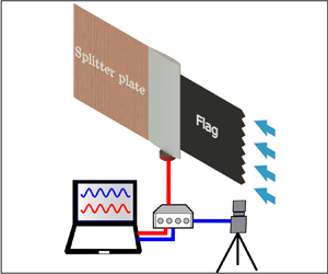
In order to investigate experimentally the existence of synchronization between the lift force and displacement for heavy inverted flags, stainless-steel flags of varying length (hence, varying mass ratio), labelled S1 to S4, were tested (see table 2). The transverse (lift) and streamwise (drag) components of the fluid flow force were measured simultaneously at the flagpole, utilizing an in-house built aerodynamic balance (Mini45-E Array Technology Incorporated). Time traces of the lift,  $F_{L}(0,t)$, and the drag,
  $F_{D}(0,t)$, components (see figure 2) were collected at
  ${1000}\ \textrm {Hz}$; the sampling rate for the tip transverse displacement,
  $w(L,t)$, was
  $160\text {--}{280}\ \textrm {Hz}$ (see Tavallaeinejad (Reference Tavallaeinejad2020) for more details).
Table 2. Stainless-steel inverted flags utilized in experiments;  $H=75\ \textrm {mm}$ and
  $h=0.08\ \textrm {mm}$.

 $^{a}$Note that the dimensionless frequency can be obtained as
  $f^{*}=f\sqrt {\rho _{f}h/D}\,L^{2}$.
2.3.1. Frequency characteristics
Figure 7 shows the time trace and power spectral density (PSD) plots for the dimensionless tip transverse displacement,  $w(L,t)/L$, and lift for flag S1 at different flow velocities: (a,b)
  $U=5.7\ \textrm {m}\ \textrm {s}^{-1}$ (
 $\varPi =2.08$), (c,d)
  $U=7.7\ \textrm {m}\ \textrm {s}^{-1}$ (
 $\varPi =2.81$), and (e,f)
  $U=8.3\ \textrm {m}\ \textrm {s}^{-1}$ (
 $\varPi =3.03$). In the PSD plots for the lift signal, the peaks are labelled sequentially as
  $f_{L1}$,
  $f_{L2}$, etc., from low to high frequencies. As seen in figure 7(b,d),
  $f_{1} = f_{L1}$, where
  $f_{1}$ is the displacement dominant frequency. Also, from the lift PSD,
  $f_{L1}$ has several higher harmonics, such as
  $f_{L2}$ and
  $f_{L3}$, with comparable powers, while in the displacement PSD, only one predominant frequency harmonic exists, supporting the observations by Goza et al. (Reference Goza, Colonius and Sader2018) discussed above. By increasing the flow velocity, motion becomes chaotic-like at
  $U=8.3\ \textrm {m}\ \textrm {s}^{-1}$ (
 $\varPi =3.03$). As seen from the lift PSD,
  $f_{L2}$ becomes the dominant frequency, while still
  $f_{1} = f_{L1}$; the loss of 1 : 1 synchronization with departure from a periodic behaviour can also be seen in figure 7(e,f). One may conclude from figure 7(a–f) that, by increasing the flow velocity, the dynamics of the flag and that of the flow become more complex, leading eventually to chaotic-like motion. This is evidenced by the increase of irregularity in the time histories and the fact that the spectra show a broader range of frequencies with a distinct subdominant peak in the PSD of lift. The increase of decoherence between the flag displacement and lift, as the flow velocity is increased, should also be noted.

Figure 7. (a,c,e) Time traces, (b,d,f) PSDs and (g,h) spectrograms for flag S1: (a,b)  $U=5.7\ \textrm {m}\ \textrm {s}^{-1}$ (
 $\varPi =2.08$); (c,d)
  $U=7.7\ \textrm {m}\ \textrm {s}^{-1}$ (
 $\varPi =2.81$); and (e,f)
  $U=8.3\ \textrm {m}\ \textrm {s}^{-1}$ (
 $\varPi =3.03$). Results are for tip transverse displacement and normalized lift
  $\bar {F}_{L}$, as indicated. Power spectrum in dB.
The spectrograms of the displacement and lift signals are presented in figure 7(g,h), respectively, showing an increase in the dynamic activity with increasing flow velocity. In particular, the lift spectrogram shows the presence of multiple frequencies with comparable powers, which are distinguishable for most of the flow velocity range. This suggests that the wake flow contains vortices of comparable strength, shed at different frequencies (including the flapping frequency), indicating that the vortex shedding does not fully control the flapping. Nevertheless, detailed studies of the flow dynamics, perhaps via PIV measurements, are required to validate what was discussed above; such experiments are deferred to future investigations.
Figure 8 shows the time trace and PSD plots for (a,b) flag S2, (c,d) flag S3, and (e,f) flag S4, respectively. Similarly to the discussion on figure 7, the displacement PSDs show that the power is mostly centred around one frequency (i.e.  $f_1$), while the lift PSDs show an almost evenly distributed power over multiple frequencies. For example, as shown in figure 8(d) for flag S3, the dominant displacement frequency is
  $f_1=18\ \textrm {Hz}$, while that for the lift is
  $f_{L3}=36\ \textrm {Hz}$. There are also other peaks in the lift PSD, which occur at
  $f_{L1}=14.1$,
  $f_{L2}=f_{1}=18$,
  $f_{L4}=3f_1=54$ and
  $f_{L5}=5f_1=90\ \textrm {Hz}$; however, no similarly strong peaks can be found in the displacement frequency content. This indicates that vortex shedding may be synchronized to a higher displacement harmonic; in the present case, the vortex shedding frequency is twice the flapping frequency, giving rise to a 1 : 2 synchronization. The difference between the dominant (peak) frequencies of the lift and flapping for flag S2 is illustrated further through spectrograms shown in figure 8(g,h).

Figure 8. (a,c,e) Time traces and (b,d,f) PSD plots for flags S2 to S4, respectively: (a,b)  $U=7.4\ \textrm {m}\ \textrm {s}^{-1}$ (
 $\varPi =1.58$); (c,d)
  $U=14.4\ \textrm {m}\ \textrm {s}^{-1}$ (
 $\varPi =1.86$); and (e,f)
  $U=19.0\ \textrm {m}\ \textrm {s}^{-1}$ (
 ${\varPi =1.44}$). Results are for tip transverse displacement and normalized lift
  $\bar {F}_{L}$, as indicated. (g,h) Spectrogram plots for flag S2. Power spectrum in dB.
2.3.2. Phase dynamics
It is known that in the case of VIV-driven motion of a circular cylinder in cross-flow, as the flow velocity is varied, sharp changes occur in the phase difference between the fluid forces and cylinder motion at resonance. In particular, the phase between the cross-flow force (i.e. lift) and the transverse displacement of the cylinder jumps from nearly  $0$ to about
  ${\rm \pi}$ (see Khalak & Williamson Reference Khalak and Williamson1999; Zhao et al. Reference Zhao, Leontini, Lo Jacono and Sheridan2014; Seyed-Aghazadeh, Carlson & Modarres-Sadeghi Reference Seyed-Aghazadeh, Carlson and Modarres-Sadeghi2017).
In this paper, the instantaneous phase difference between the time series obtained for the transverse displacement of the flag and the lift are calculated using the Hilbert transform (Khalak & Williamson Reference Khalak and Williamson1999; Konstantinidis et al. Reference Konstantinidis, Zhao, Jacono, Leontini and Sheridan2019). The instantaneous phase is defined as  $\phi _{w}(t)=\operatorname {atan}[w(L,t)/\hat {w}(L,t)]$ and
  $\phi _{F}(t)=\operatorname {atan}[F_{L}(0,t)/\hat {F}_{L}(0,t)]$, where
  $\hat {w}(L,t)$ and
  $\hat {F}_{L}(0,t)$ are the Hilbert transforms of
  $w(L,t)$ and
  $F_{L}(0,t)$, respectively. Next, the instantaneous phase difference,
  $\phi _{d}(t)$, between lift and displacement is calculated as
  $\phi _{d}(t)=\phi _{F}(t)-\phi _{w}(t)$.
Figure 9 shows the time-averaged phase difference  $\phi _{d}$ as a function of the dimensionless flow velocity for flags S1 to S4 listed in table 2. In all the cases, the time-averaged phase difference never crosses
  $90^{\circ }$ and remains bounded in the
  $[0^{\circ }\ 50^{\circ }]$ range over the large-amplitude flapping regime. The different values of the phase difference may well be due to the effect of different structural damping for the different flags. (Similar observations have been made by Seyed-Aghazadeh et al. (Reference Seyed-Aghazadeh, Carlson and Modarres-Sadeghi2017) for triangular prisms in cross-flow, who reported that no jump occurred from
  ${\sim }0$ to
  ${\sim }180^{\circ }$ in phase difference between flow forces and body motion, hence concluding that the oscillation was of the galloping type.)

Figure 9. Time-averaged phase difference between transverse force (lift) and transverse displacement for flag S1 (black squares), flag S2 (red circles), flag S3 (blue diamonds) and flag S4 (green triangles) over the periodic large-amplitude flapping regime.
The above observations suggest that flag motion and vortex shedding influence each other reciprocally; however, vortex shedding does not appear to be the cause for flapping of, at least, heavy inverted flags. Instead, the large-amplitude flapping of heavy inverted flags accompanied by high-frequency vortex shedding suggests that self-excited vibration may be the underlying mechanism, meaning that time-averaged movement-induced aerodynamic forces govern the motion. A similar conclusion has been reached for slender prismatic bodies with bluff cross-section and sufficiently long afterbody in cross-flow by Nemes et al. (Reference Nemes, Zhao, Jacono and Sheridan2012), Zhao et al. (Reference Zhao, Leontini, Lo Jacono and Sheridan2014) and Seyed-Aghazadeh et al. (Reference Seyed-Aghazadeh, Carlson and Modarres-Sadeghi2017), among others. The present observations also agree well with the computational predictions of Goza et al. (Reference Goza, Colonius and Sader2018), who report that, for heavy flags, the dominant frequency of lift (corresponding to the highest peak in the PSD plot) is greater than that of the tip displacement, suggesting that the motion is not ‘classical VIV’.
Finally, it is recalled that, according to a well-known classification by Naudascher & Rockwell (Reference Naudascher and Rockwell1994), flow-induced vibrations are divided into three types: (i) extraneously induced excitation, (ii) instability-induced excitation, and (iii) movement-induced excitation (or self-excited vibration). Turbulence buffeting and VIV are classic examples of the first and second types, respectively, while flutter of an aircraft wing and of a cantilevered pipe conveying fluid are examples of the last type. If the flapping of heavy inverted flags is not an extraneously induced excitation (since the turbulence intensity was kept very low in our wind tunnel experiments) or an instability-induced excitation (as argued above), then, by induction, it has to be a movement-induced excitation.
3. Conclusion
Some experiments were described in this paper, aiming to examine the global dynamics of heavy inverted flags and, in particular, to evaluate the impact of periodic vortex shedding from the leading and trailing edges thereon.
The effects of adding serrations to the leading edge and a long rigid splitter plate to the trailing edge were investigated: only minor changes in the critical flow velocity, amplitude and frequency of oscillations resulted thereby. The overall dynamics and its features remained unchanged, and large-amplitude flapping was observed for all flags tested in the experiments, with or without the serrations and the splitter plate. With the splitter plate, TEVs are formed and shed from the free end of the plate (that is, far from the flag), the effect of which on the flow field close to the flag is minimal; also, interactions between the two counter-rotating LEVs (if they are not completely disrupted by serrations) are inhibited by the splitter plate.
Force measurements provided some insight into the relationship between vortex shedding and large-amplitude flapping; a difference between the dominant (peak) frequencies of the lift and flapping was found in some cases. Moreover, it was shown that, for heavier inverted flags, additional peaks, with power as great as or larger than that matching the dominant motion frequency, appear in the lift frequency spectrum. In addition, the lift and tip displacement were found to be desynchronized in the chaotic-like flow regime.
The experimental results presented in §§ 2.1–2.3 suggest that self-excited vibration via a fluid-elastic instability may be the underlying mechanism for the flapping motion of heavy inverted flags. The nearly identical qualitative behaviour of plain inverted flags and those with a serrated leading edge and a splitter plate at the trailing edge suggests that the global (qualitative) dynamical characteristics of heavy inverted flags are not governed by the unsteady vortex shedding from the leading and/or trailing edges. In other words, periodic vortex shedding is not the cause, but an effect of large-amplitude flapping.
It is stressed that no flow visualization was carried out in the experiments with serrated flags and the splitter plate, and thus no information can be provided regarding the vortex formation and shedding from the leading and trailing edges. Nevertheless, PIV measurements conducted by Pazhani (Reference Pazhani2018) showed that complex three-dimensional flow near the serrations disrupts regular vortex formation and shedding from the leading edge – LEVs become more stable and their periodic formation and shedding are delayed.
There are definitely potential correlations, yet to be discovered, between the phase dynamics and the underlying mechanism for large-amplitude flapping. Further investigations would be desirable to better clarify the distinction between VIV and the underlying mechanism for large-amplitude flapping of heavy flags.
Acknowledgements
The authors gratefully acknowledge the financial support by the Natural Sciences and Engineering Research Council of Canada, the Solution Mining Research Institute and Pipeline Research Council International. It is a pleasure to acknowledge the benefit of insightful comments by Professor John E. Sader.
Declaration of interests
The authors report no conflict of interest.


