


1. Introduction
Flow over porous media is encountered in many technological and physical processes, such as liquid coating, oil refinement, river beds, ground flow or heat exchangers of open-cell metal foam. Atmospheric flows over densely built-up urban areas and plant canopies are additional examples of turbulent flow over porous media (Finnigan Reference Finnigan2000). This wide range of applications has motivated the present study, aiming to characterize the turbulent flow through a square duct with three solid walls and a permeable bottom wall. Previous experimental studies dealing with the effect of wall permeability on turbulence (Zagni & Smith Reference Zagni and Smith1976; Zippe & Graf Reference Zippe and Graf1983) have shown that the friction factor is higher than that measured over impermeable walls with the same surface roughness. As discussed by Zagni & Smith (Reference Zagni and Smith1976), the momentum transfer across the porous interface leads to increased energy dissipation, significantly modifying the structure of turbulence. Since experimental studies do not allow one to easily identify the contributions of wall permeability and of roughness on the flow, numerical studies are used to address this particular issue. Breugem, Boersma & Uittenbogaard (Reference Breugem, Boersma and Uittenbogaard2006) performed a direct numerical simulation (DNS) of the turbulent flow through a plane channel over a permeable wall by considering the continuum or one-domain approach (Whitaker Reference Whitaker1996), where the volume-averaged Navier–Stokes (VANS) equations are solved. In this approach, continuous spatial variations of permeability and porosity throughout the interface are imposed in order to take into account the effect of momentum exchange across the permeable wall.
The VANS model is used here to study the turbulent flow through a porous square duct, a flow case that allows one to study wall-bounded turbulence in a relatively simple configuration, yet with two inhomogeneous directions. The most interesting feature of duct flows is the appearance of the so-called Prandtl’s secondary flow of the second kind (Prandtl Reference Prandtl1926) at the duct corners, which is the result of the cross-stream Reynolds stress difference and the deviatoric Reynolds shear-stress gradients. This secondary flow consists of four pairs of counter-rotating vortices located at the duct corners that convect momentum from the duct centre towards the corner bisectors. Several experimental studies have been carried out to investigate the origin of this secondary motion, the mean flow velocities and the associated Reynolds stresses (see e.g. Gessner Reference Gessner1973). The underlying physical mechanism is studied numerically by Huser & Biringen (Reference Huser and Biringen1993) and Pinelli et al. (Reference Pinelli, Uhlmann, Sekimoto and Kawahara2010), who examined the buffer layer coherent structures and the bursting phenomena responsible for the generation of the secondary mean flow. The impact of the duct aspect ratio (defined as its total width divided by its height) on the secondary flow was assessed numerically by Vinuesa et al. (Reference Vinuesa, Noorani, Lozano-Durán, El Khoury, Schlatter, Fischer and Nagib2014) and Vinuesa, Schlatter & Nagib (Reference Vinuesa, Schlatter and Nagib2015b ).
In this study we use DNS to evaluate how the secondary flow of the second kind is affected by the presence of a permeable wall. The numerical code is validated against available results of flow through a porous channel (Breugem et al. Reference Breugem, Boersma and Uittenbogaard2006), and excellent agreement is achieved. Our simulation shows that the presence of the permeable wall significantly impacts the magnitude of the secondary flow, which increases by a factor of four compared with the equivalent duct with four solid walls when scaled with the bulk velocity. This may have important implications, for example, for pollutant mixing and to evaluate experimental data. Experiments of turbulent flows over sediment beds are often performed in open channels of small or intermediate aspect ratio, where the effects of secondary motions cannot be discarded.

Figure 1. (a) Schematic diagram of a turbulent flow through a channel or duct with lower permeable wall and (b) instantaneous streamwise velocity field from the porous duct simulation (note that the flow is from right to left). A cut through the duct centreplane (
 $z/H=0$
) is shown, and the top solid wall is removed, to allow proper flow visualization.
$z/H=0$
) is shown, and the top solid wall is removed, to allow proper flow visualization.
2. Governing equations
Consider a fully developed wall-bounded turbulent flow with a lower permeable wall, e.g. a packed bed of spheres, characterized by a given porosity (fluid volume fraction) and mean particle diameter (Breugem et al.
Reference Breugem, Boersma and Uittenbogaard2006). A sketch of the flow configuration is shown in figure 1(a). We assume a viscous, incompressible and Newtonian fluid, and denote the streamwise, wall-normal and spanwise directions as
 $x$
,
$x$
,
 $y$
and
$y$
and
 $z$
, respectively. Since the focus of the present study is on the effect of permeability on the turbulent flow structure, additional effects due to the impermeability of the lower wall are excluded by considering a porous layer at least as thick as the fluid layer, i.e.
$z$
, respectively. Since the focus of the present study is on the effect of permeability on the turbulent flow structure, additional effects due to the impermeability of the lower wall are excluded by considering a porous layer at least as thick as the fluid layer, i.e.
 $d=H$
. In a microscopic sense, the flow through the porous medium is possible only through the pores and can be described by the Navier–Stokes equations. In order to study the macroscale system behaviour, it is necessary to use an up-scaling procedure to develop a modified form of the Navier–Stokes equations valid in the entire porous medium. The derivation of the VANS equations is performed by the method of volume averaging (Whitaker Reference Whitaker1996). In this continuum approach, the fluid and porous media are considered as a single composite medium. The flow in this medium is governed by the VANS equations, written in dimensionless form as
$d=H$
. In a microscopic sense, the flow through the porous medium is possible only through the pores and can be described by the Navier–Stokes equations. In order to study the macroscale system behaviour, it is necessary to use an up-scaling procedure to develop a modified form of the Navier–Stokes equations valid in the entire porous medium. The derivation of the VANS equations is performed by the method of volume averaging (Whitaker Reference Whitaker1996). In this continuum approach, the fluid and porous media are considered as a single composite medium. The flow in this medium is governed by the VANS equations, written in dimensionless form as
 $$\begin{eqnarray}\boldsymbol{{\rm\nabla}}\boldsymbol{\cdot }[{\it\varepsilon}\boldsymbol{u}]=0,\end{eqnarray}$$
 $$\begin{eqnarray}\displaystyle \partial _{t}\boldsymbol{u} & = & \displaystyle -\frac{1}{{\it\varepsilon}}\boldsymbol{{\rm\nabla}}\boldsymbol{\cdot }[{\it\varepsilon}\boldsymbol{u}\otimes \boldsymbol{u}]-\boldsymbol{{\rm\nabla}}p+\frac{1}{\mathit{Re}_{b}}{\rm\nabla}^{2}\boldsymbol{u}+\frac{1}{{\it\varepsilon}\mathit{Re}_{b}}\boldsymbol{{\rm\nabla}}{\it\varepsilon}\boldsymbol{\cdot }\boldsymbol{{\rm\nabla}}\boldsymbol{u}\nonumber\\ \displaystyle & & \displaystyle -\,\frac{1}{\mathit{Re}_{b}}\frac{\mathit{Fo}}{\mathit{Da}}{\it\varepsilon}|\boldsymbol{u}|\boldsymbol{u}+\frac{1}{\mathit{Re}_{b}}\left[\frac{{\rm\nabla}^{2}{\it\varepsilon}}{{\it\varepsilon}}-\frac{{\it\varepsilon}}{\mathit{Da}}\right]\boldsymbol{u},\end{eqnarray}$$
where
 $\boldsymbol{u}$
is the volume average of the fluid velocity
$\boldsymbol{u}$
is the volume average of the fluid velocity
 $\hat{\boldsymbol{u}}$
in the porous medium (
$\hat{\boldsymbol{u}}$
in the porous medium (
 $\boldsymbol{u}=(1/{\it\Omega}_{f})\int _{{\it\Omega}}\hat{\boldsymbol{u}}\,\text{d}{\it\Omega}$
), and
$\boldsymbol{u}=(1/{\it\Omega}_{f})\int _{{\it\Omega}}\hat{\boldsymbol{u}}\,\text{d}{\it\Omega}$
), and
 $\boldsymbol{u}=\hat{\boldsymbol{u}}$
in the fluid side. Note that a unit volume in the porous medium is defined as
$\boldsymbol{u}=\hat{\boldsymbol{u}}$
in the fluid side. Note that a unit volume in the porous medium is defined as
 ${\it\Omega}={\it\Omega}_{f}+{\it\Omega}_{s}$
(where both fluid and solid contributions are considered), and
${\it\Omega}={\it\Omega}_{f}+{\it\Omega}_{s}$
(where both fluid and solid contributions are considered), and
 ${\it\varepsilon}$
is the porosity. Boundary conditions at the fluid–porous interface are not required in this formulation. The porosity of the medium is a function of space, and varies rapidly in a small region of thickness
${\it\varepsilon}$
is the porosity. Boundary conditions at the fluid–porous interface are not required in this formulation. The porosity of the medium is a function of space, and varies rapidly in a small region of thickness
 ${\it\delta}_{i}$
below the fluid–porous interface. The value of
${\it\delta}_{i}$
below the fluid–porous interface. The value of
 ${\it\varepsilon}$
evolves from a constant value
${\it\varepsilon}$
evolves from a constant value
 ${\it\varepsilon}_{c}$
in the homogeneous porous region to one in the homogeneous fluid region. Following Breugem et al. (Reference Breugem, Boersma and Uittenbogaard2006), the porosity is set to
${\it\varepsilon}_{c}$
in the homogeneous porous region to one in the homogeneous fluid region. Following Breugem et al. (Reference Breugem, Boersma and Uittenbogaard2006), the porosity is set to
 $$\begin{eqnarray}{\it\varepsilon}=\left\{\begin{array}{@{}ll@{}}1,\quad & \phantom{-}0\leqslant y\leqslant H\\ -6({\it\varepsilon}_{c}-1)(y/{\it\delta}_{i})^{5}-15({\it\varepsilon}_{c}-1)(y/{\it\delta}_{i})^{4}-10({\it\varepsilon}_{c}-1)(y/{\it\delta}_{i})^{3}+1,\quad & -{\it\delta}_{i}\leqslant y\leqslant 0,\\ {\it\varepsilon}_{c},\quad & -H\leqslant y\leqslant -{\it\delta}_{i}.\end{array}\right.\end{eqnarray}$$
The permeability
 $K$
and the Forchheimer coefficient
$K$
and the Forchheimer coefficient
 $\tilde{F}$
are defined as (Breugem et al.
Reference Breugem, Boersma and Uittenbogaard2006):
$\tilde{F}$
are defined as (Breugem et al.
Reference Breugem, Boersma and Uittenbogaard2006):
 $$\begin{eqnarray}\displaystyle K=\frac{d_{p}^{2}{\it\varepsilon}^{3}}{180(1-{\it\varepsilon})^{2}},\quad \tilde{F}=\frac{{\it\varepsilon}}{100(1-{\it\varepsilon})}\frac{d_{p}}{{\it\nu}}, & & \displaystyle\end{eqnarray}$$
where
 $d_{p}$
is the mean particle diameter in the porous medium. Note that
$d_{p}$
is the mean particle diameter in the porous medium. Note that
 $K$
takes a constant value in the homogeneous porous region, and goes to
$K$
takes a constant value in the homogeneous porous region, and goes to
 $\infty$
in the fluid region. Equations (2.1) and (2.2) are non-dimensionalized with the fluid layer thickness
$\infty$
in the fluid region. Equations (2.1) and (2.2) are non-dimensionalized with the fluid layer thickness
 $H$
and the bulk velocity through the fluid medium
$H$
and the bulk velocity through the fluid medium
 $U_{b}$
. The governing dimensionless parameters are the bulk Reynolds number
$U_{b}$
. The governing dimensionless parameters are the bulk Reynolds number
 $\mathit{Re}_{b}=U_{b}H/{\it\nu}$
(where
$\mathit{Re}_{b}=U_{b}H/{\it\nu}$
(where
 ${\it\nu}$
is the fluid kinematic viscosity), the Darcy number
${\it\nu}$
is the fluid kinematic viscosity), the Darcy number
 $\mathit{Da}=K/H^{2}$
and the Forchheimer number
$\mathit{Da}=K/H^{2}$
and the Forchheimer number
 $\mathit{Fo}=\tilde{F}U_{b}$
.
$\mathit{Fo}=\tilde{F}U_{b}$
.
3. Numerical procedure
The DNS of the VANS equations are carried out with the spectral element code Nek5000 developed by Fischer, Lottes & Kerkemeier (Reference Fischer, Lottes and Kerkemeier2008), which has been extensively used to study turbulent flows in a number of internal and external configurations (Noorani, El Khoury & Schlatter Reference Noorani, El Khoury and Schlatter2013; Vinuesa et al.
Reference Vinuesa, Schlatter, Malm, Mavriplis and Henningson2015a
). The spectral element method (SEM) combines the geometrical flexibility of finite element methods with the local accuracy of spectral methods. Within each spectral element, the three-dimensional velocity field is expanded by means of a tensor product of Legendre polynomials of order
 $N$
(the pressure is expanded in terms of polynomials of order
$N$
(the pressure is expanded in terms of polynomials of order
 $N-2$
), and the
$N-2$
), and the
 $N+1$
grid points follow the Gauss–Lobatto–Legendre (GLL) distribution. The additional forcing terms associated with the VANS equations were implemented in the SEM code, and their validation is discussed in § 3.1. Complete turbulence statistics and budgets are computed during the simulation, and stored for later post-processing.
$N+1$
grid points follow the Gauss–Lobatto–Legendre (GLL) distribution. The additional forcing terms associated with the VANS equations were implemented in the SEM code, and their validation is discussed in § 3.1. Complete turbulence statistics and budgets are computed during the simulation, and stored for later post-processing.
All simulations are started from a laminar flow, with the same spectral element distribution but lower polynomial order (
 $N=5$
). A localized wall-normal volume force is used during the first 50 convective time units (the time is non-dimensionalized in terms of
$N=5$
). A localized wall-normal volume force is used during the first 50 convective time units (the time is non-dimensionalized in terms of
 $U_{b}$
and
$U_{b}$
and
 $H$
) to trip a rapid turbulent breakdown as described by Schlatter & Örlü (Reference Schlatter and Örlü2012). During the following 50 time units, the polynomial order was increased to seven, the forcing set to zero, and the forcing from the VANS equations turned on. At this point, the interpolation order is increased to
$H$
) to trip a rapid turbulent breakdown as described by Schlatter & Örlü (Reference Schlatter and Örlü2012). During the following 50 time units, the polynomial order was increased to seven, the forcing set to zero, and the forcing from the VANS equations turned on. At this point, the interpolation order is increased to
 $N=11$
to fully resolve the self-sustained turbulent flow over the porous bed. This procedure allows a progressive development and ensures numerical stability when introducing the effect of the permeable wall. Based on previous convergence analyses (Vinuesa et al.
Reference Vinuesa, Noorani, Lozano-Durán, El Khoury, Schlatter, Fischer and Nagib2014), it is possible to collect statistics from this point, avoiding initial transients.
$N=11$
to fully resolve the self-sustained turbulent flow over the porous bed. This procedure allows a progressive development and ensures numerical stability when introducing the effect of the permeable wall. Based on previous convergence analyses (Vinuesa et al.
Reference Vinuesa, Noorani, Lozano-Durán, El Khoury, Schlatter, Fischer and Nagib2014), it is possible to collect statistics from this point, avoiding initial transients.

Figure 2. Statistics for the porous channel DNS: (a) comparison of the streamwise mean velocity
 $U$
normalized by the bulk velocity
$U$
normalized by the bulk velocity
 $U_{b}$
, (b) r.m.s. velocities normalized by
$U_{b}$
, (b) r.m.s. velocities normalized by
 $u_{{\it\tau}}^{p}$
, and (c,d) terms in the TKE budget of
$u_{{\it\tau}}^{p}$
, and (c,d) terms in the TKE budget of
 $\overline{u^{\prime 2}}/2$
normalized by
$\overline{u^{\prime 2}}/2$
normalized by
 $(u_{{\it\tau}}^{p})^{3}/{\it\delta}_{w}$
. Lines indicate present results and symbols data by Breugem et al. (Reference Breugem, Boersma and Uittenbogaard2006).
$(u_{{\it\tau}}^{p})^{3}/{\it\delta}_{w}$
. Lines indicate present results and symbols data by Breugem et al. (Reference Breugem, Boersma and Uittenbogaard2006).
3.1. Validation of the code
The present approach is validated by computing the porous channel flow configuration described by Breugem et al. (Reference Breugem, Boersma and Uittenbogaard2006), with a porosity of
 ${\it\varepsilon}_{c}=0.95$
and a bulk Reynolds number of
${\it\varepsilon}_{c}=0.95$
and a bulk Reynolds number of
 $\mathit{Re}_{b}\simeq 5500$
. This value was chosen to produce significant momentum transfer across the fluid–porous interface. Periodic boundary conditions are imposed in the streamwise and spanwise directions, and the computational box has dimensions
$\mathit{Re}_{b}\simeq 5500$
. This value was chosen to produce significant momentum transfer across the fluid–porous interface. Periodic boundary conditions are imposed in the streamwise and spanwise directions, and the computational box has dimensions
 $L_{x}=5H$
,
$L_{x}=5H$
,
 $L_{y}=2H$
and
$L_{y}=2H$
and
 $L_{z}=3H$
, with the porous layer located from
$L_{z}=3H$
, with the porous layer located from
 $y=-H$
to 0. The flow is driven by a streamwise pressure gradient, which is adjusted every time step to produce a constant bulk velocity of 1 over the whole cross-sectional area. Note that
$y=-H$
to 0. The flow is driven by a streamwise pressure gradient, which is adjusted every time step to produce a constant bulk velocity of 1 over the whole cross-sectional area. Note that
 $\mathit{Re}_{b}$
is defined in terms of
$\mathit{Re}_{b}$
is defined in terms of
 $U_{b}$
, which is the bulk velocity over the
$U_{b}$
, which is the bulk velocity over the
 $H\times H$
fluid region, and therefore is not prescribed in the simulation but calculated from the resulting mean flow (in this case,
$H\times H$
fluid region, and therefore is not prescribed in the simulation but calculated from the resulting mean flow (in this case,
 $U_{b}\simeq 1.95$
). The mean particle diameter is
$U_{b}\simeq 1.95$
). The mean particle diameter is
 $d_{p}=0.01H$
, and the interface region thickness is taken as
$d_{p}=0.01H$
, and the interface region thickness is taken as
 ${\it\delta}_{i}=0.02H$
. As discussed by Breugem et al. (Reference Breugem, Boersma and Uittenbogaard2006), two boundary layers develop within the channel fluid region: one above the permeable wall and one below the top wall. The location at which the two boundary layers meet is denoted by
${\it\delta}_{i}=0.02H$
. As discussed by Breugem et al. (Reference Breugem, Boersma and Uittenbogaard2006), two boundary layers develop within the channel fluid region: one above the permeable wall and one below the top wall. The location at which the two boundary layers meet is denoted by
 $y={\it\delta}_{w}$
(which is where the mean velocity
$y={\it\delta}_{w}$
(which is where the mean velocity
 $U$
reaches its maximum). The mesh was designed to satisfy the typical resolution requirements in DNS of wall-bounded turbulence, so the maximum spacing in the streamwise direction is
$U$
reaches its maximum). The mesh was designed to satisfy the typical resolution requirements in DNS of wall-bounded turbulence, so the maximum spacing in the streamwise direction is
 ${\rm\Delta}x^{t+}=7.9$
(based on the friction velocity on the top wall
${\rm\Delta}x^{t+}=7.9$
(based on the friction velocity on the top wall
 $u_{{\it\tau}}^{t}$
) or
$u_{{\it\tau}}^{t}$
) or
 ${\rm\Delta}x^{p+}=13.5$
(in terms of the friction velocity over the permeable wall
${\rm\Delta}x^{p+}=13.5$
(in terms of the friction velocity over the permeable wall
 $u_{{\it\tau}}^{p}$
). Note that here ‘
$u_{{\it\tau}}^{p}$
). Note that here ‘
 $+$
’ stands for scaling with the corresponding viscous length
$+$
’ stands for scaling with the corresponding viscous length
 $\ell ^{\ast }={\it\nu}/u_{{\it\tau}}$
, where
$\ell ^{\ast }={\it\nu}/u_{{\it\tau}}$
, where
 $u_{{\it\tau}}=\sqrt{{\it\tau}_{w}/{\it\rho}}$
is the friction velocity,
$u_{{\it\tau}}=\sqrt{{\it\tau}_{w}/{\it\rho}}$
is the friction velocity,
 ${\it\tau}_{w}$
is the wall shear stress and
${\it\tau}_{w}$
is the wall shear stress and
 ${\it\rho}$
is the fluid density. In the spanwise direction, the mesh satisfies
${\it\rho}$
is the fluid density. In the spanwise direction, the mesh satisfies
 ${\rm\Delta}z^{t+}\simeq 5$
and
${\rm\Delta}z^{t+}\simeq 5$
and
 ${\rm\Delta}z^{p+}=8.6$
. The mesh in the fluid medium was designed such that, for the boundary layer developing below the top wall,
${\rm\Delta}z^{p+}=8.6$
. The mesh in the fluid medium was designed such that, for the boundary layer developing below the top wall,
 ${\rm\Delta}y_{min}^{t+}=0.13$
,
${\rm\Delta}y_{min}^{t+}=0.13$
,
 ${\rm\Delta}y_{max}^{t+}=3.2$
, and for the one over the fluid–porous interface,
${\rm\Delta}y_{max}^{t+}=3.2$
, and for the one over the fluid–porous interface,
 ${\rm\Delta}y_{min}^{p+}=0.22$
,
${\rm\Delta}y_{min}^{p+}=0.22$
,
 ${\rm\Delta}y_{max}^{p+}=5.4$
. A total of 10 spectral elements are used between
${\rm\Delta}y_{max}^{p+}=5.4$
. A total of 10 spectral elements are used between
 $y=-H$
and 0, with one element located at
$y=-H$
and 0, with one element located at
 $y/H=-{\it\delta}_{i}$
. This yields a total of around 63 million grid points for the channel configuration. Differences between results obtained on this mesh and a finer one with two elements between
$y/H=-{\it\delta}_{i}$
. This yields a total of around 63 million grid points for the channel configuration. Differences between results obtained on this mesh and a finer one with two elements between
 $y/H=-{\it\delta}_{i}$
and 0 were found to be of the order of 1 %. Therefore, this resolution was considered sufficient to properly capture the physics at the fluid–porous interface.
$y/H=-{\it\delta}_{i}$
and 0 were found to be of the order of 1 %. Therefore, this resolution was considered sufficient to properly capture the physics at the fluid–porous interface.
The mean and root-mean-square (r.m.s.) velocities are illustrated in figure 2(a,b), where an excellent agreement with the results of Breugem et al. (Reference Breugem, Boersma and Uittenbogaard2006) is observed. Note that the mean velocity deviates from the one typical of turbulent channel flows with solid walls, and is different from zero at the fluid–porous interface. Also, its maximum is located in the upper half of the fluid layer. The wall permeability increases the skin friction coefficient
 $C_{f}=2(u_{{\it\tau}}^{p}/U_{b})^{2}$
to a value 74 % larger than that over an impermeable wall due to the non-zero Reynolds shear stress
$C_{f}=2(u_{{\it\tau}}^{p}/U_{b})^{2}$
to a value 74 % larger than that over an impermeable wall due to the non-zero Reynolds shear stress
 $\overline{u^{\prime }v^{\prime }}$
at the fluid–porous interface. The terms of the turbulence kinetic energy (TKE) budget of the streamwise turbulence intensity
$\overline{u^{\prime }v^{\prime }}$
at the fluid–porous interface. The terms of the turbulence kinetic energy (TKE) budget of the streamwise turbulence intensity
 $\overline{u^{\prime 2}}/2$
are given by (3.1), where the summation convention is adopted:
$\overline{u^{\prime 2}}/2$
are given by (3.1), where the summation convention is adopted:
 $$\begin{eqnarray}\displaystyle \partial _{t}(\overline{u^{\prime 2}}/2) & = & \displaystyle -\underbrace{\overline{u^{\prime }\partial _{x}p^{\prime }}}_{\text{P}}+\underbrace{\frac{1}{\mathit{Re}_{b}}\partial _{x_{j}x_{j}}^{2}(\overline{u^{\prime 2}}/2)}_{\text{VD}}-\underbrace{\frac{1}{\mathit{Re}_{b}}\overline{(\partial _{x_{j}}u^{\prime })^{2}}}_{\text{D}}-\underbrace{\partial _{x_{j}}(\overline{u^{\prime 2}u_{j}^{\prime }}/2)-\frac{1}{{\it\varepsilon}}\partial _{y}{\it\varepsilon}[\overline{u^{\prime 2}v^{\prime }}]}_{\text{TT}}\nonumber\\ \displaystyle & & \displaystyle -\,\underbrace{\overline{u^{\prime }u_{j}^{\prime }}\partial _{x_{j}U}}_{\text{WS}}-\underbrace{U_{j}\partial _{x_{j}}(\overline{u^{\prime 2}}/2)-\frac{1}{{\it\varepsilon}}\partial _{y}{\it\varepsilon}[U\overline{u^{\prime }v^{\prime }}+\overline{u^{\prime 2}}V]}_{\text{CON}}\nonumber\\ \displaystyle & & \displaystyle +\,\underbrace{\frac{1}{\mathit{Re}_{b}}\left[\partial _{yy}^{2}{\it\varepsilon}(\overline{u^{\prime 2}}/{\it\varepsilon})+\frac{1}{{\it\varepsilon}}\partial _{y}{\it\varepsilon}\partial _{y}(\overline{u^{\prime 2}}/2)\right]}_{\text{POR}}-\underbrace{\frac{1}{\mathit{Re}_{b}}\frac{{\it\varepsilon}}{\mathit{Da}}\overline{u^{\prime 2}}}_{\text{DAR}}-\underbrace{\frac{1}{\mathit{Re}_{b}}\frac{\mathit{Fo}}{\mathit{Da}}{\it\varepsilon}\overline{|\tilde{\boldsymbol{u}}|\tilde{u} u^{\prime }}}_{\text{FOR}}.\nonumber\\ \displaystyle & & \displaystyle\end{eqnarray}$$
These terms are shown in figure 2(c,d), where we first note that the viscous diffusion VD and the viscous dissipation D are less significant than the energy production term WS close to the fluid–porous interface because of the relaxation of the no-slip and no-penetration conditions. Note that the work by the Forchheimer drag, FOR, is the dominant loss term close the fluid–porous interface. In the porous layer region, the term P is a local balance of FOR and DAR, where DAR is the work of Darcy drag. The present results agree well with those by Breugem et al. (Reference Breugem, Boersma and Uittenbogaard2006), with a small discrepancy in the maximum values of the WS, TT and FOR. These terms involve double
 $\overline{u_{i}^{\prime }u_{j}^{\prime }}$
and triple
$\overline{u_{i}^{\prime }u_{j}^{\prime }}$
and triple
 $\overline{u_{i}^{\prime }u_{j}^{\prime }u_{k}^{\prime }}$
correlations and require long averaging times to obtain statistically converged results. The simulations were averaged for
$\overline{u_{i}^{\prime }u_{j}^{\prime }u_{k}^{\prime }}$
correlations and require long averaging times to obtain statistically converged results. The simulations were averaged for
 ${\rm\Delta}T_{b}=53$
convective time units in Breugem et al. (Reference Breugem, Boersma and Uittenbogaard2006), whereas we average over
${\rm\Delta}T_{b}=53$
convective time units in Breugem et al. (Reference Breugem, Boersma and Uittenbogaard2006), whereas we average over
 ${\rm\Delta}T_{b}=520$
, which, together with the current higher discretization order, can explain the observed differences. The main characteristics of the simulations are presented in table 1.
${\rm\Delta}T_{b}=520$
, which, together with the current higher discretization order, can explain the observed differences. The main characteristics of the simulations are presented in table 1.
Table 1. Characteristics of the various flow cases, with Reynolds numbers
 $\mathit{Re}_{b}\simeq 5500$
in the channels and
$\mathit{Re}_{b}\simeq 5500$
in the channels and
 $\mathit{Re}_{b}\simeq 5000$
in the ducts. The superscripts
$\mathit{Re}_{b}\simeq 5000$
in the ducts. The superscripts
 $t$
and
$t$
and
 $p$
stand for top and permeable bottom wall regions, where
$p$
stand for top and permeable bottom wall regions, where
 $\mathit{Re}_{{\it\tau}}^{p}=u_{{\it\tau}}^{p}H/{\it\nu}$
,
$\mathit{Re}_{{\it\tau}}^{p}=u_{{\it\tau}}^{p}H/{\it\nu}$
,
 $\mathit{Re}_{K}=\sqrt{K({\it\varepsilon}_{c})}u_{{\it\tau}}^{p}/{\it\nu}$
,
$\mathit{Re}_{K}=\sqrt{K({\it\varepsilon}_{c})}u_{{\it\tau}}^{p}/{\it\nu}$
,
 $\mathit{Re}_{d}=u_{{\it\tau}}^{p}d_{p}/{\it\nu}$
,
$\mathit{Re}_{d}=u_{{\it\tau}}^{p}d_{p}/{\it\nu}$
,
 $\mathit{Re}_{{\it\delta}}^{p}=u_{{\it\tau}}^{p}{\it\delta}_{w}/{\it\nu}$
and
$\mathit{Re}_{{\it\delta}}^{p}=u_{{\it\tau}}^{p}{\it\delta}_{w}/{\it\nu}$
and
 $\mathit{Re}_{{\it\delta}}^{t}=u_{{\it\tau}}^{t}(H-{\it\delta}_{w})/{\it\nu}$
. Note that in the porous duct case the friction velocity values are averaged over the corresponding wall, and in the duct from Vinuesa et al. (Reference Vinuesa, Noorani, Lozano-Durán, El Khoury, Schlatter, Fischer and Nagib2014) the average is over the four walls. In the two duct cases, the value
$\mathit{Re}_{{\it\delta}}^{t}=u_{{\it\tau}}^{t}(H-{\it\delta}_{w})/{\it\nu}$
. Note that in the porous duct case the friction velocity values are averaged over the corresponding wall, and in the duct from Vinuesa et al. (Reference Vinuesa, Noorani, Lozano-Durán, El Khoury, Schlatter, Fischer and Nagib2014) the average is over the four walls. In the two duct cases, the value
 ${\it\delta}_{w,c}$
at the spanwise centreplane is considered.
${\it\delta}_{w,c}$
at the spanwise centreplane is considered.

4. Results for the square duct
We next present the results for the porous duct. As for the channel, the porous layer extends from
 $y=-H$
to 0, and the fluid phase from
$y=-H$
to 0, and the fluid phase from
 $y=0$
to
$y=0$
to
 $H$
, with the lateral walls located at
$H$
, with the lateral walls located at
 $z=-0.5H$
and
$z=-0.5H$
and
 $0.5H$
, which corresponds to a square duct of dimensions
$0.5H$
, which corresponds to a square duct of dimensions
 $H\times H$
over the fluid–porous interface. Periodicity is considered in the streamwise direction, where the domain is
$H\times H$
over the fluid–porous interface. Periodicity is considered in the streamwise direction, where the domain is
 $12.5H$
long (as for the square duct simulations by Vinuesa et al. (Reference Vinuesa, Noorani, Lozano-Durán, El Khoury, Schlatter, Fischer and Nagib2014)), sufficient to capture the longest streamwise turbulent structures. Also in this case
$12.5H$
long (as for the square duct simulations by Vinuesa et al. (Reference Vinuesa, Noorani, Lozano-Durán, El Khoury, Schlatter, Fischer and Nagib2014)), sufficient to capture the longest streamwise turbulent structures. Also in this case
 ${\it\varepsilon}_{c}=0.95$
,
${\it\varepsilon}_{c}=0.95$
,
 $d_{p}=0.01H$
,
$d_{p}=0.01H$
,
 ${\it\delta}_{i}=0.02H$
and
${\it\delta}_{i}=0.02H$
and
 $\mathit{Re}_{b}\simeq 5000$
, the value considered in the duct simulation by Vinuesa et al. (Reference Vinuesa, Noorani, Lozano-Durán, El Khoury, Schlatter, Fischer and Nagib2014). The mesh is generated following the same guidelines as in § 3.1 for the porous and rigid walls, i.e. for the boundary layer below the top wall, the maximum spacing in the wall-normal direction satisfies
$\mathit{Re}_{b}\simeq 5000$
, the value considered in the duct simulation by Vinuesa et al. (Reference Vinuesa, Noorani, Lozano-Durán, El Khoury, Schlatter, Fischer and Nagib2014). The mesh is generated following the same guidelines as in § 3.1 for the porous and rigid walls, i.e. for the boundary layer below the top wall, the maximum spacing in the wall-normal direction satisfies
 ${\rm\Delta}y_{min}^{t+}=0.13$
and
${\rm\Delta}y_{min}^{t+}=0.13$
and
 ${\rm\Delta}y_{max}^{t+}=3.2$
. The mesh at the boundary layer over the fluid–porous interface satisfies
${\rm\Delta}y_{max}^{t+}=3.2$
. The mesh at the boundary layer over the fluid–porous interface satisfies
 ${\rm\Delta}y_{min}^{p+}=0.22$
and
${\rm\Delta}y_{min}^{p+}=0.22$
and
 ${\rm\Delta}y_{max}^{p+}=5.4$
. Since the duct is not homogeneous in the spanwise direction, the mesh in
${\rm\Delta}y_{max}^{p+}=5.4$
. Since the duct is not homogeneous in the spanwise direction, the mesh in
 $z$
is designed similarly to the one in
$z$
is designed similarly to the one in
 $y$
, i.e. satisfies
$y$
, i.e. satisfies
 ${\rm\Delta}z_{min}^{t+}=0.13$
and
${\rm\Delta}z_{min}^{t+}=0.13$
and
 ${\rm\Delta}z_{max}^{t+}=3.2$
. A total of 10 spectral elements are used between
${\rm\Delta}z_{max}^{t+}=3.2$
. A total of 10 spectral elements are used between
 $y=-H$
and 0, with one element located at
$y=-H$
and 0, with one element located at
 $y/H=-{\it\delta}_{i}$
. Note that this mesh results in a total of approximately 93 million grid points. All the statistics presented in this study were collected over
$y/H=-{\it\delta}_{i}$
. Note that this mesh results in a total of approximately 93 million grid points. All the statistics presented in this study were collected over
 ${\rm\Delta}T_{b}=1040$
convective time units, and more details of this simulation are summarized in table 1.
${\rm\Delta}T_{b}=1040$
convective time units, and more details of this simulation are summarized in table 1.

Figure 3. (a,c) Streamwise mean velocity
 $U$
normalized by bulk velocity
$U$
normalized by bulk velocity
 $U_{b}$
from the porous channel (solid), porous duct (dashed) and the duct from Vinuesa et al. (Reference Vinuesa, Noorani, Lozano-Durán, El Khoury, Schlatter, Fischer and Nagib2014) (dotted). (b,d) The r.m.s. velocities normalized by
$U_{b}$
from the porous channel (solid), porous duct (dashed) and the duct from Vinuesa et al. (Reference Vinuesa, Noorani, Lozano-Durán, El Khoury, Schlatter, Fischer and Nagib2014) (dotted). (b,d) The r.m.s. velocities normalized by
 $u_{{\it\tau}}^{p}$
from the porous duct (lines) and the duct from Vinuesa et al. (Reference Vinuesa, Noorani, Lozano-Durán, El Khoury, Schlatter, Fischer and Nagib2014) (symbols). The profiles in (a,b) are extracted at the centreplane, those in (c,d) at
$u_{{\it\tau}}^{p}$
from the porous duct (lines) and the duct from Vinuesa et al. (Reference Vinuesa, Noorani, Lozano-Durán, El Khoury, Schlatter, Fischer and Nagib2014) (symbols). The profiles in (a,b) are extracted at the centreplane, those in (c,d) at
 $z/H=0.45$
.
$z/H=0.45$
.
Figure 3(a) shows the streamwise velocity at the centreplane of the porous duct, compared with the duct from Vinuesa et al. (Reference Vinuesa, Noorani, Lozano-Durán, El Khoury, Schlatter, Fischer and Nagib2014) and the porous channel. First, it is interesting to note that the maximum velocity normalized by
 $U_{b}$
is larger in the porous duct than in the porous channel, which is due to the fact that the sidewall and top boundary layers accelerate the core of the flow. Second, the value of
$U_{b}$
is larger in the porous duct than in the porous channel, which is due to the fact that the sidewall and top boundary layers accelerate the core of the flow. Second, the value of
 ${\it\delta}_{w,c}$
(which is the location where the two boundary layers merge at the centreplane of the duct) is very similar for the two ducts (
${\it\delta}_{w,c}$
(which is the location where the two boundary layers merge at the centreplane of the duct) is very similar for the two ducts (
 $y=0.55$
in the porous case and
$y=0.55$
in the porous case and
 $y=0.5$
in the impermeable duct), and significantly lower than in the porous channel (
$y=0.5$
in the impermeable duct), and significantly lower than in the porous channel (
 $y=0.74$
). The boundary layer developing over the fluid–porous interface becomes thicker when the flow is not constrained in the spanwise direction, therefore highlighting the significant momentum redistribution induced by the sidewalls at the core of the duct. One of the most relevant features from the porous channel (Breugem et al.
Reference Breugem, Boersma and Uittenbogaard2006) is also observed in figure 3(b): the streamwise turbulence intensity normalized by
$y=0.74$
). The boundary layer developing over the fluid–porous interface becomes thicker when the flow is not constrained in the spanwise direction, therefore highlighting the significant momentum redistribution induced by the sidewalls at the core of the duct. One of the most relevant features from the porous channel (Breugem et al.
Reference Breugem, Boersma and Uittenbogaard2006) is also observed in figure 3(b): the streamwise turbulence intensity normalized by
 $u_{{\it\tau}}^{p}$
is significantly lower in the porous duct than in the duct with four solid walls. Since the solid wall on the bottom is replaced by a permeable wall, the characteristic buffer layer structures of wall-bounded turbulence are absent, and, instead, the short spanwise rollers observed in figure 1(b) are found. Jiménez et al. (Reference Jiménez, Uhlmann, Pinelli and Kawahara2001) reported the presence of large spanwise rollers in their spanwise-periodic simulations of turbulent shear flow over porous surfaces, and showed that they originated from the Kelvin–Helmholtz type of instability of the shear layer at the interface and from neutral inviscid shear waves of the mean turbulent profile. In the present case, these structures, which might originate from similar mechanisms, are constrained in the spanwise direction by the sidewalls and therefore have a short spanwise extent of approximately
$u_{{\it\tau}}^{p}$
is significantly lower in the porous duct than in the duct with four solid walls. Since the solid wall on the bottom is replaced by a permeable wall, the characteristic buffer layer structures of wall-bounded turbulence are absent, and, instead, the short spanwise rollers observed in figure 1(b) are found. Jiménez et al. (Reference Jiménez, Uhlmann, Pinelli and Kawahara2001) reported the presence of large spanwise rollers in their spanwise-periodic simulations of turbulent shear flow over porous surfaces, and showed that they originated from the Kelvin–Helmholtz type of instability of the shear layer at the interface and from neutral inviscid shear waves of the mean turbulent profile. In the present case, these structures, which might originate from similar mechanisms, are constrained in the spanwise direction by the sidewalls and therefore have a short spanwise extent of approximately
 ${\it\Delta}_{z}\simeq 0.4H$
. The larger peaks in
${\it\Delta}_{z}\simeq 0.4H$
. The larger peaks in
 $v_{rms}$
and
$v_{rms}$
and
 $w_{rms}$
, also observed in the channel flow by Breugem et al. (Reference Breugem, Boersma and Uittenbogaard2006), are produced by the significant wall-normal momentum transport across the fluid–porous interface. Although the two cross-flow fluctuating components are larger in the porous duct, the maximum of the turbulent kinetic energy is still larger in the presence of four solid walls. Streamwise velocity and streamwise turbulence intensity profiles are shown for the porous duct and the one with solid walls at
$w_{rms}$
, also observed in the channel flow by Breugem et al. (Reference Breugem, Boersma and Uittenbogaard2006), are produced by the significant wall-normal momentum transport across the fluid–porous interface. Although the two cross-flow fluctuating components are larger in the porous duct, the maximum of the turbulent kinetic energy is still larger in the presence of four solid walls. Streamwise velocity and streamwise turbulence intensity profiles are shown for the porous duct and the one with solid walls at
 $z/H=0.45$
in figure 3(c,d), respectively. Note that the mean velocity profile is significantly modified by the effect of the sidewall: in the duct with solid walls, two small peaks emerge in the vicinity of the top and bottom walls, whereas in the porous duct, a relative maximum is observed close to the top wall and the maximum velocity is located at around
$z/H=0.45$
in figure 3(c,d), respectively. Note that the mean velocity profile is significantly modified by the effect of the sidewall: in the duct with solid walls, two small peaks emerge in the vicinity of the top and bottom walls, whereas in the porous duct, a relative maximum is observed close to the top wall and the maximum velocity is located at around
 $y/H\simeq 0.5$
. Regarding the fluctuations closer to the corner, the maximum in the streamwise turbulence intensity from the porous duct is only slightly reduced with respect to the value at the centreplane. On the other hand, the effect of the sidewall in both wall-normal and spanwise fluctuations is much larger, with significantly reduced values close to the interface. Interestingly, the effect of the sidewall on the turbulence fluctuations is larger in the duct with solid walls, especially in the case of the streamwise turbulence intensity, as discussed by Vinuesa et al. (Reference Vinuesa, Noorani, Lozano-Durán, El Khoury, Schlatter, Fischer and Nagib2014).
$y/H\simeq 0.5$
. Regarding the fluctuations closer to the corner, the maximum in the streamwise turbulence intensity from the porous duct is only slightly reduced with respect to the value at the centreplane. On the other hand, the effect of the sidewall in both wall-normal and spanwise fluctuations is much larger, with significantly reduced values close to the interface. Interestingly, the effect of the sidewall on the turbulence fluctuations is larger in the duct with solid walls, especially in the case of the streamwise turbulence intensity, as discussed by Vinuesa et al. (Reference Vinuesa, Noorani, Lozano-Durán, El Khoury, Schlatter, Fischer and Nagib2014).

Figure 4. (a) Streamlines of secondary mean flow
 ${\it\psi}$
computed using
${\it\psi}$
computed using
 $U_{b}$
and
$U_{b}$
and
 $H$
as velocity and length scales, with increments of
$H$
as velocity and length scales, with increments of
 $5\times 10^{-4}$
(same increments in the solid duct). Grey lines correspond to clockwise sense of rotation, and black lines to anticlockwise. Contours of mean velocity
$5\times 10^{-4}$
(same increments in the solid duct). Grey lines correspond to clockwise sense of rotation, and black lines to anticlockwise. Contours of mean velocity
 $U$
normalized by
$U$
normalized by
 $U_{b}$
are also shown on half of the domain. (b) Cross-flow velocity magnitude
$U_{b}$
are also shown on half of the domain. (b) Cross-flow velocity magnitude
 $\sqrt{V^{2}+W^{2}}$
normalized by
$\sqrt{V^{2}+W^{2}}$
normalized by
 $U_{b}$
; (e) r.m.s. of the streamwise turbulence intensity scaled with
$U_{b}$
; (e) r.m.s. of the streamwise turbulence intensity scaled with
 $u_{{\it\tau}}^{p}$
; and (f) production of
$u_{{\it\tau}}^{p}$
; and (f) production of
 $\overline{u^{\prime 2}}/2$
normalized with
$\overline{u^{\prime 2}}/2$
normalized with
 $(u_{{\it\tau}}^{p})^{3}/{\it\delta}_{w,c}$
(here the maximum value is 59.8, although the colour bar is restricted to values up to 25). All these quantities are shown for the porous duct, whereas in (c,d,g,h) they are shown for a solid duct (see Vinuesa et al.
Reference Vinuesa, Noorani, Lozano-Durán, El Khoury, Schlatter, Fischer and Nagib2014). In the solid duct, the
$(u_{{\it\tau}}^{p})^{3}/{\it\delta}_{w,c}$
(here the maximum value is 59.8, although the colour bar is restricted to values up to 25). All these quantities are shown for the porous duct, whereas in (c,d,g,h) they are shown for a solid duct (see Vinuesa et al.
Reference Vinuesa, Noorani, Lozano-Durán, El Khoury, Schlatter, Fischer and Nagib2014). In the solid duct, the
 $u_{{\it\tau}}$
value is obtained as the average over the four walls.
$u_{{\it\tau}}$
value is obtained as the average over the four walls.
The main feature of a turbulent duct is the secondary flow of the second kind (Prandtl Reference Prandtl1926), which as mentioned in § 1 is produced at the corners. Figure 4(a,c) shows the streamlines of the mean cross-flow (together with a contour plot of the streamwise velocity). Whereas the duct simulation by Vinuesa et al. (Reference Vinuesa, Noorani, Lozano-Durán, El Khoury, Schlatter, Fischer and Nagib2014) shows the characteristic eight counter-rotating vortices convecting momentum from the duct centreplane towards the corner bisectors, the present results show a significantly distorted pattern. The wall-normal momentum transport produces a very interesting phenomenon, namely that only four vortices are present in the porous case, and are significantly stretched in the
 $y$
direction. Focusing on the left half of the porous duct, the two vortices between
$y$
direction. Focusing on the left half of the porous duct, the two vortices between
 $y/H=0$
and 0.5 disappear, and the vortex sitting on the top wall is squeezed along the sidewall by the effect of the large
$y/H=0$
and 0.5 disappear, and the vortex sitting on the top wall is squeezed along the sidewall by the effect of the large
 $V$
component. The remaining vortex is now at the porous interface, and basically convects momentum from the core of the duct towards the sidewall. Note that on the top wall the cross-flow still convects momentum from the core of the duct towards the sidewall. The secondary flow is further characterized through contours of the cross-flow velocity magnitude
$V$
component. The remaining vortex is now at the porous interface, and basically convects momentum from the core of the duct towards the sidewall. Note that on the top wall the cross-flow still convects momentum from the core of the duct towards the sidewall. The secondary flow is further characterized through contours of the cross-flow velocity magnitude
 $\sqrt{V^{2}+W^{2}}$
scaled with
$\sqrt{V^{2}+W^{2}}$
scaled with
 $U_{b}$
– see figure 4(b,d) for the porous and solid ducts, respectively. The secondary flow is around four times stronger in the porous duct, a phenomenon produced by the much larger
$U_{b}$
– see figure 4(b,d) for the porous and solid ducts, respectively. The secondary flow is around four times stronger in the porous duct, a phenomenon produced by the much larger
 $V$
, but also by the absence of the solid wall, which significantly reduces viscous dissipation. In this sense, the vertical flow from the large vortices on the top wall is convected through the interface, instead of dissipated at the bisector, leading to the enhanced secondary flow (as also observed from the streamlines).
$V$
, but also by the absence of the solid wall, which significantly reduces viscous dissipation. In this sense, the vertical flow from the large vortices on the top wall is convected through the interface, instead of dissipated at the bisector, leading to the enhanced secondary flow (as also observed from the streamlines).
As reported by Huser & Biringen (Reference Huser and Biringen1993), the origin of the secondary flow is the interaction between the ejection phenomena from the horizontal walls and those from the vertical walls, which effectively leads to a redistribution of energy from
 $\overline{v^{\prime 2}}$
to
$\overline{v^{\prime 2}}$
to
 $\overline{w^{\prime 2}}$
. In this case the anisotropy of the Reynolds stress tensor is produced by the interactions between the ejections from the sidewalls and the motions present over the permeable wall, which exhibit larger values of both
$\overline{w^{\prime 2}}$
. In this case the anisotropy of the Reynolds stress tensor is produced by the interactions between the ejections from the sidewalls and the motions present over the permeable wall, which exhibit larger values of both
 $\overline{v^{\prime 2}}$
and
$\overline{v^{\prime 2}}$
and
 $\overline{w^{\prime 2}}$
, as shown in figure 3(b). Therefore, the enhanced secondary flow is produced both by the increased mean vertical velocity and by the enhanced cross-flow turbulence intensities. Although the porous duct exhibits increased secondary flow magnitude, figure 3(b) shows that its streamwise turbulence intensity is significantly reduced at the centreplane. Contour plots of the streamwise turbulence intensity are shown in figure 4(e,g) for the porous and solid ducts, respectively. The maximum
$\overline{w^{\prime 2}}$
, as shown in figure 3(b). Therefore, the enhanced secondary flow is produced both by the increased mean vertical velocity and by the enhanced cross-flow turbulence intensities. Although the porous duct exhibits increased secondary flow magnitude, figure 3(b) shows that its streamwise turbulence intensity is significantly reduced at the centreplane. Contour plots of the streamwise turbulence intensity are shown in figure 4(e,g) for the porous and solid ducts, respectively. The maximum
 $u_{rms}$
scaled with
$u_{rms}$
scaled with
 $u_{{\it\tau}}^{p}$
is around 65 % larger in the duct with four solid walls than in the porous duct, and the very different buffer layer behaviour mentioned above is more noticeable in figure 4(e). It is also interesting to observe that the two sidewalls exhibit similar turbulence intensity as in the case with four solid walls, but with reduced magnitude. As in the case of the porous channel, the top wall is significantly affected by the phenomena taking place at the boundary layer developing over the permeable wall. The interesting features of the secondary flow over a porous bed can be further analysed based on the production of
$u_{{\it\tau}}^{p}$
is around 65 % larger in the duct with four solid walls than in the porous duct, and the very different buffer layer behaviour mentioned above is more noticeable in figure 4(e). It is also interesting to observe that the two sidewalls exhibit similar turbulence intensity as in the case with four solid walls, but with reduced magnitude. As in the case of the porous channel, the top wall is significantly affected by the phenomena taking place at the boundary layer developing over the permeable wall. The interesting features of the secondary flow over a porous bed can be further analysed based on the production of
 $\overline{u^{\prime 2}}/2$
, shown in figure 4(f,h). These panels show the effect of the Reynolds shear stresses
$\overline{u^{\prime 2}}/2$
, shown in figure 4(f,h). These panels show the effect of the Reynolds shear stresses
 $\overline{u^{\prime }v^{\prime }}$
and
$\overline{u^{\prime }v^{\prime }}$
and
 $\overline{u^{\prime }w^{\prime }}$
, where the maximum production corresponding to the porous duct is around 2.4 times larger than in the solid duct when scaled with
$\overline{u^{\prime }w^{\prime }}$
, where the maximum production corresponding to the porous duct is around 2.4 times larger than in the solid duct when scaled with
 $(u_{{\it\tau}}^{p})^{3}/{\it\delta}_{w,c}$
. In fact, the maximum production of the porous duct is slightly shifted towards
$(u_{{\it\tau}}^{p})^{3}/{\it\delta}_{w,c}$
. In fact, the maximum production of the porous duct is slightly shifted towards
 $y/H=0$
, which is consistent with the larger velocity gradients and non-zero values of the Reynolds shear stresses. The production contours also highlight the role of the flow close to the corner (at around
$y/H=0$
, which is consistent with the larger velocity gradients and non-zero values of the Reynolds shear stresses. The production contours also highlight the role of the flow close to the corner (at around
 $z/H=0.45$
), where the strong
$z/H=0.45$
), where the strong
 $V$
is found, and the deformation of the secondary flow (compared with the solid duct) takes place. Here is where the maximum production is located, as opposed to the duct with solid walls, where the maximum production is found at
$V$
is found, and the deformation of the secondary flow (compared with the solid duct) takes place. Here is where the maximum production is located, as opposed to the duct with solid walls, where the maximum production is found at
 $z/H=0$
.
$z/H=0$
.

Figure 5. Variation of streamwise pressure–strain correlation
 $\unicode[STIX]{x1D617}\unicode[STIX]{x1D61A}_{xx}=(2/{\it\rho})\overline{p^{\prime }\partial _{x}u^{\prime }}$
as a function of the wall-normal coordinate
$\unicode[STIX]{x1D617}\unicode[STIX]{x1D61A}_{xx}=(2/{\it\rho})\overline{p^{\prime }\partial _{x}u^{\prime }}$
as a function of the wall-normal coordinate
 $y$
at two different spanwise locations: (a)
$y$
at two different spanwise locations: (a)
 $z=0$
and (b)
$z=0$
and (b)
 $z=0.45H$
.
$z=0.45H$
.
 $\unicode[STIX]{x1D617}\unicode[STIX]{x1D61A}_{xx}$
is normalized by
$\unicode[STIX]{x1D617}\unicode[STIX]{x1D61A}_{xx}$
is normalized by
 $(u_{{\it\tau}}^{p})^{3}/{\it\delta}_{w,c}$
for the porous duct, and by
$(u_{{\it\tau}}^{p})^{3}/{\it\delta}_{w,c}$
for the porous duct, and by
 $(u_{{\it\tau}})^{3}/{\it\delta}_{w,c}$
for the duct with solid walls; and
$(u_{{\it\tau}})^{3}/{\it\delta}_{w,c}$
for the duct with solid walls; and
 $y$
is normalized by
$y$
is normalized by
 ${\it\delta}_{w,c}$
. Here solid, dashed and dotted lines represent porous channel, porous duct and duct with solid walls, respectively.
${\it\delta}_{w,c}$
. Here solid, dashed and dotted lines represent porous channel, porous duct and duct with solid walls, respectively.
The fluctuating pressure
 $p^{\prime }$
appears in the balance of the Reynolds stresses
$p^{\prime }$
appears in the balance of the Reynolds stresses
 $\overline{u_{i}^{\prime }u_{j}^{\prime }}$
through the velocity–pressure gradient tensor
$\overline{u_{i}^{\prime }u_{j}^{\prime }}$
through the velocity–pressure gradient tensor
 ${\it\Pi}_{ij}$
, defined as
${\it\Pi}_{ij}$
, defined as
 $$\begin{eqnarray}{\it\Pi}_{ij}=-\frac{1}{{\it\rho}}\overline{(u_{i}^{\prime }\partial _{x_{j}}p^{\prime }+u_{j}^{\prime }\partial _{x_{i}}p^{\prime })}.\end{eqnarray}$$
This tensor can be further decomposed into two parts,
 ${\it\Pi}_{ij}=\unicode[STIX]{x1D617}\unicode[STIX]{x1D61A}_{ij}+\unicode[STIX]{x1D61B}_{ij}^{P}$
, as follows:
${\it\Pi}_{ij}=\unicode[STIX]{x1D617}\unicode[STIX]{x1D61A}_{ij}+\unicode[STIX]{x1D61B}_{ij}^{P}$
, as follows:
 $$\begin{eqnarray}\unicode[STIX]{x1D617}\unicode[STIX]{x1D61A}_{ij}=\overline{\frac{p^{\prime }}{{\it\rho}}(\partial _{x_{j}}u_{i}^{\prime }+\partial _{x_{i}}u_{j}^{\prime })},\quad \unicode[STIX]{x1D61B}_{ij}^{P}=-\frac{1}{{\it\rho}}\overline{(\partial _{x_{j}}u_{i}^{\prime }p^{\prime }+\partial _{x_{i}}u_{j}^{\prime }p^{\prime })},\end{eqnarray}$$
where
 $\unicode[STIX]{x1D617}\unicode[STIX]{x1D61A}_{ij}$
is the pressure–rate of strain tensor and
$\unicode[STIX]{x1D617}\unicode[STIX]{x1D61A}_{ij}$
is the pressure–rate of strain tensor and
 $\unicode[STIX]{x1D61B}_{ij}^{P}$
is the pressure–transport term. Note that the pressure gradient term P in the streamwise kinetic energy budget (3.1) can be recast as
$\unicode[STIX]{x1D61B}_{ij}^{P}$
is the pressure–transport term. Note that the pressure gradient term P in the streamwise kinetic energy budget (3.1) can be recast as
 $$\begin{eqnarray}P\equiv -\overline{u^{\prime }\partial _{x}p^{\prime }}=\frac{{\it\Pi}_{xx}}{2}=\frac{\unicode[STIX]{x1D61B}_{xx}}{2}+\frac{\unicode[STIX]{x1D617}\unicode[STIX]{x1D61A}_{xx}}{2},\end{eqnarray}$$
which shows that the term
 $\unicode[STIX]{x1D617}\unicode[STIX]{x1D61A}_{ij}$
plays an important role in the redistribution of energy among the Reynolds stresses. To further understand its effect on the porous duct case, the term
$\unicode[STIX]{x1D617}\unicode[STIX]{x1D61A}_{ij}$
plays an important role in the redistribution of energy among the Reynolds stresses. To further understand its effect on the porous duct case, the term
 $\unicode[STIX]{x1D617}\unicode[STIX]{x1D61A}_{xx}$
is shown in figure 5 at two different spanwise locations (
$\unicode[STIX]{x1D617}\unicode[STIX]{x1D61A}_{xx}$
is shown in figure 5 at two different spanwise locations (
 $z/H=0$
and 0.45) and compared with the porous channel and the square duct with solid walls. At the centreplane, the porous channel exhibits a maximum value of
$z/H=0$
and 0.45) and compared with the porous channel and the square duct with solid walls. At the centreplane, the porous channel exhibits a maximum value of
 $\unicode[STIX]{x1D617}\unicode[STIX]{x1D61A}_{xx}$
around 40 % larger than that in the porous duct, and approximately six times larger than that from the duct with solid walls. The maximum values of
$\unicode[STIX]{x1D617}\unicode[STIX]{x1D61A}_{xx}$
around 40 % larger than that in the porous duct, and approximately six times larger than that from the duct with solid walls. The maximum values of
 $\unicode[STIX]{x1D617}\unicode[STIX]{x1D61A}_{xx}$
are reduced close to the sidewall by around 20 % in both ducts, the value from the porous one still being around four times larger than the one observed in the duct with solid walls. It is important to note that, since the sign of
$\unicode[STIX]{x1D617}\unicode[STIX]{x1D61A}_{xx}$
are reduced close to the sidewall by around 20 % in both ducts, the value from the porous one still being around four times larger than the one observed in the duct with solid walls. It is important to note that, since the sign of
 ${\it\Pi}_{xx}$
is opposite to that of
${\it\Pi}_{xx}$
is opposite to that of
 $\unicode[STIX]{x1D617}\unicode[STIX]{x1D61A}_{xx}$
and
$\unicode[STIX]{x1D617}\unicode[STIX]{x1D61A}_{xx}$
and
 $\unicode[STIX]{x1D61B}_{xx}$
, this term acts as an energy transportation term, and therefore in the porous duct the pressure gradient term
$\unicode[STIX]{x1D61B}_{xx}$
, this term acts as an energy transportation term, and therefore in the porous duct the pressure gradient term
 $P={\it\Pi}_{xx}/2$
drains much more energy from the streamwise turbulence intensity than in the regular duct. This explains the results observed in figure 3, where the streamwise turbulence intensity
$P={\it\Pi}_{xx}/2$
drains much more energy from the streamwise turbulence intensity than in the regular duct. This explains the results observed in figure 3, where the streamwise turbulence intensity
 $\overline{u^{\prime 2}}$
is smaller in the porous duct than in the one with solid walls, whereas the in-plane turbulence intensities
$\overline{u^{\prime 2}}$
is smaller in the porous duct than in the one with solid walls, whereas the in-plane turbulence intensities
 $\overline{v^{\prime 2}}$
and
$\overline{v^{\prime 2}}$
and
 $\overline{w^{\prime 2}}$
are increased. Therefore, an effective energy transfer from the streamwise to the cross-stream turbulence intensities is observed. Furthermore, the viscous dissipation term D,
$\overline{w^{\prime 2}}$
are increased. Therefore, an effective energy transfer from the streamwise to the cross-stream turbulence intensities is observed. Furthermore, the viscous dissipation term D,
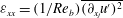 ${\it\varepsilon}_{xx}=(1/\mathit{Re}_{b})\overline{(\partial _{x_{j}}u^{\prime })^{2}}$
, is reduced due to the presence of the permeable wall. This analysis based on the pressure–strain correlation is consistent with the observations from figure 4, where the production in the porous duct was shown to be around 2.4 times larger than in the regular duct.
${\it\varepsilon}_{xx}=(1/\mathit{Re}_{b})\overline{(\partial _{x_{j}}u^{\prime })^{2}}$
, is reduced due to the presence of the permeable wall. This analysis based on the pressure–strain correlation is consistent with the observations from figure 4, where the production in the porous duct was shown to be around 2.4 times larger than in the regular duct.
5. Summary and conclusions
The turbulent flow through a square duct over a permeable wall was studied by means of DNS. The permeable wall is considered as a packed bed, where the main defining parameters are the porosity and the particle diameter, and the VANS equations are used to describe the flow through it. These equations were implemented in the spectral element code Nek5000 (Fischer et al.
Reference Fischer, Lottes and Kerkemeier2008), and the method was first validated by computing the turbulent flow through a plane channel over a permeable wall, as described by Breugem et al. (Reference Breugem, Boersma and Uittenbogaard2006). Our channel results show very good agreement with the literature data in terms of mean flow, fluctuations and the TKE budget of
 $\overline{u^{\prime 2}}/2$
. After validating our numerical set-up, we simulated a duct where the fluid and porous phases have cross-sectional areas of
$\overline{u^{\prime 2}}/2$
. After validating our numerical set-up, we simulated a duct where the fluid and porous phases have cross-sectional areas of
 $H\times H$
. The first interesting difference between the porous duct and the channel is the value of
$H\times H$
. The first interesting difference between the porous duct and the channel is the value of
 ${\it\delta}_{w,c}$
(the location where the two fluid boundary layers merge, evaluated at the duct centreplane), which is 0.55, significantly closer to the centre than that of the porous channel (0.75). This is due to the effect of the sidewall boundary layers, which inhibit the growth of the boundary layer over the porous interface, and accelerate the core of the duct. Another important feature observed in the porous duct is the decrease in streamwise turbulence intensity (also observed in the channel), which is consistent with the replacement of the bottom solid wall by a permeable wall. This produces short spanwise rollers that might result from a Kelvin–Helmholtz type of instability (which are constrained in the spanwise direction and show an extent of around
${\it\delta}_{w,c}$
(the location where the two fluid boundary layers merge, evaluated at the duct centreplane), which is 0.55, significantly closer to the centre than that of the porous channel (0.75). This is due to the effect of the sidewall boundary layers, which inhibit the growth of the boundary layer over the porous interface, and accelerate the core of the duct. Another important feature observed in the porous duct is the decrease in streamwise turbulence intensity (also observed in the channel), which is consistent with the replacement of the bottom solid wall by a permeable wall. This produces short spanwise rollers that might result from a Kelvin–Helmholtz type of instability (which are constrained in the spanwise direction and show an extent of around
 ${\it\Delta}_{z}\simeq 0.4H$
), and not the typical buffer layer streaky structures of wall-bounded turbulence. The most relevant feature is that the secondary flow increases in the porous duct with respect to a duct with four solid walls, and the cross-flow pattern is significantly distorted: a total of four counter-rotating vortices are present in this flow, instead of the eight characteristic of the duct with four solid walls. The larger
${\it\Delta}_{z}\simeq 0.4H$
), and not the typical buffer layer streaky structures of wall-bounded turbulence. The most relevant feature is that the secondary flow increases in the porous duct with respect to a duct with four solid walls, and the cross-flow pattern is significantly distorted: a total of four counter-rotating vortices are present in this flow, instead of the eight characteristic of the duct with four solid walls. The larger
 $V$
velocity component convects momentum through the interface, and it is not dissipated at the bisector as in the duct with four solid walls. This leads to a secondary flow, which exceeds by a factor of four (when scaled with
$V$
velocity component convects momentum through the interface, and it is not dissipated at the bisector as in the duct with four solid walls. This leads to a secondary flow, which exceeds by a factor of four (when scaled with
 $U_{b}$
) the one found in the solid duct. The interaction of ejections from the vertical and horizontal walls are the origin of the secondary flow. Here the more complicated dynamics of the ejections from the sidewalls and flow over the permeable wall, combined with the enhanced values of
$U_{b}$
) the one found in the solid duct. The interaction of ejections from the vertical and horizontal walls are the origin of the secondary flow. Here the more complicated dynamics of the ejections from the sidewalls and flow over the permeable wall, combined with the enhanced values of
 $\overline{v^{\prime 2}}$
and
$\overline{v^{\prime 2}}$
and
 $\overline{w^{\prime 2}}$
over the fluid–porous interface, greatly contribute to increase the magnitude of the secondary flow.
$\overline{w^{\prime 2}}$
over the fluid–porous interface, greatly contribute to increase the magnitude of the secondary flow.
The relevance of the present study lies in the fact that it is a first attempt to include a porous medium in turbulent duct flows, which not only shows the permeable effect on the secondary flow, but also develops a base for future studies in this context, for example, assessment of aspect-ratio and Reynolds-number effects (it is conjectured that at higher
 $\mathit{Re}$
the two walls might start to decorrelate, thus yielding a different global scenario), experimental investigations and, more importantly, characterization of chaotic mixing phenomena when mass transfer is considered along with the flow.
$\mathit{Re}$
the two walls might start to decorrelate, thus yielding a different global scenario), experimental investigations and, more importantly, characterization of chaotic mixing phenomena when mass transfer is considered along with the flow.
Acknowledgements
A.S. acknowledges financial support from the Wenner–Gren Foundations Postdoctoral Fellowship; R.V. and P.S. acknowledge the funding provided by the Knut and Alice Wallenberg Foundation; I.L., P.S. and L.B. acknowledge financial support from the Swedish Research Council (VR), in the case of L.B. through the Outstanding Young Researcher Award. Computer time provided by the Swedish National Infrastructure for Computing (SNIC) is also gratefully acknowledged.


