


1. Introduction
Following the seminal work of Rayleigh (Reference Rayleigh1917), bubbles and their dynamics have been investigated by numerous researchers for over a century. Particular attention has been paid to their collapse phase. Scientists have tried to shed light on this microscopic – in both temporal and spatial scales – phenomenon due to the regular presence of bubbles in our world and the high energy focusing that may occur when a bubble collapses. Sonoluminescence is a phenomenon that demonstrates the high energy levels that may be reached as a bubble collapses (Gaitan et al. Reference Gaitan, Crum, Church and Roy1992; Brenner, Hilgenfeldt & Lohse Reference Brenner, Hilgenfeldt and Lohse2002). The collapse of bubbles is typically viewed in a negative light, as it is responsible for significant (and possibly catastrophic) damage on nearby surfaces, such as propellers, pumps and others (Philipp & Lauterborn Reference Philipp and Lauterborn1998). However, not all collapse events are undesired. This intense and violent process can be exploited for medical treatment (as in shock wave lithotripsy (Coleman et al. Reference Coleman, Saunders, Crum and Dyson1987; Bailey et al. Reference Bailey, Khokhlova, Sapozhnikov, Kargl and Crum2003) and histotripsy (Xu et al. Reference Xu, Raghavan, Hall, Chang, Mycek, Fowlkes and Cain2007)), for initiating or enhancing chemical activity (Suslick Reference Suslick1990; Thompson & Doraiswamy Reference Thompson and Doraiswamy1999), for sensitization of explosives (Bourne & Field Reference Bourne and Field1991) or for energy generation (as in inertial confinement fusion (Lindl Reference Lindl1995)).
1.1. Shock-induced collapse of a single bubble
The collapse of a bubble is a process primarily induced by a pressure difference. The spatial distribution of the surrounding pressure field is therefore determining the type of the collapse. A uniform field of higher exterior pressure will lead to the symmetric (Rayleigh) collapse of the bubble. In the case of a non-uniform pressure field (e.g. due to the presence of waves or nearby surfaces) the collapse of the bubble is non-spherical. Both types of collapse may be observed in nature. Bubbles, however, are mostly present in clouds and near surfaces, and the surrounding pressure field is thus distorted. Pressure transients in the form of a shock wave is a type of pressure field distortion that leads to the strong collapse of a bubble. A review of works pertaining to the interaction of bubbles with shock waves in a liquid medium was given by Ohl & Ohl (Reference Ohl and Ohl2013).
One of the first experimental studies related to the shock-induced collapse of bubbles in liquids was carried out by Tomita, Shima & Takahashi (Reference Tomita, Shima and Takahashi1983). The main parameter of interest was the wall pressure, and the details of the collapse process were not discussed in depth. Bourne & Field (Reference Bourne and Field1992) performed several experiments with varying shock pressures, cavity shapes and sizes and their results clarified for the first time all the mechanisms dominating the asymmetric collapse process. Several studies have also been carried out in the context of shock wave lithotripsy, investigating the dynamics of bubbles in response to a wave profile generated by a lithotripter (Philipp et al. Reference Philipp, Delius, Scheffczyk, Vogel and Lauterborn1993; Ohl & Ikink Reference Ohl and Ikink2003; Sankin et al. Reference Sankin, Simmons, Zhu and Zhong2005).
Numerical investigations of the shock-induced collapse of bubbles were only made possible after the development of advanced techniques for the simulation of multiphase flows. The shock-induced collapse of a bubble is nowadays commonly used as a benchmark test case for multicomponent flow solvers. Early attempts at simulating the interaction between a shock and a gas bubble in a liquid medium include the works of Grove & Menikoff (Reference Grove and Menikoff1990) and Ding & Gracewski (Reference Ding and Gracewski1996). However, as the computational resources at the time were limited, the high resolution required to capture the fine details of the collapse could not be achieved and the insight into the collapse mechanisms was limited. The first detailed simulation was carried out by Ball et al. (Reference Ball, Howell, Leighton and Schofield2000), who employed a free-Lagrange code to simulate the shock-induced collapse of a cylindrical air cavity in water. Johnsen & Colonius (Reference Johnsen and Colonius2009) developed a high-order shock- and interface-capturing scheme to solve the compressible Euler equations. The developed framework was used to investigate the axisymmetric Rayleigh and shock-induced collapses of a single gas bubble in a free field and near a wall. Their work was related to shockwave lithotripsy applications (Johnsen & Colonius Reference Johnsen and Colonius2008), and was focused on the collapsing bubbles’ potential for damage. Hawker & Ventikos (Reference Hawker and Ventikos2012) employed a highly accurate front tracking scheme to model the interaction of a strong shockwave with a gas bubble in a liquid medium. A detailed analysis of the collapse was presented, fully characterizing the involved dynamics. They also performed a parametric study over the strength of the incident shock, and detailed the observed differences in the dynamics.
1.2. Shock-induced collapse of bubble arrays
As previously mentioned, bubbles in nature are most often present in clouds. The interaction of a shock wave with an isolated bubble is therefore an idealized scenario, as the presence of neighbouring bubbles strongly influences the overall evolution of the flow, and thereby their collapse. In one of the first works to consider multiple gas bubbles, Tomita, Shima & Ohno (Reference Tomita, Shima and Ohno1984) measured the pressure induced on a solid wall when bubbles attached to it are collapsed by a shock wave. The maximum impulsive pressure was found to quickly decrease with a reduction in the spacing between the bubbles.
In a highly influential work, Dear & Field (Reference Dear and Field1988) described an experimental technique which enabled the detailed visualization of the collapse of bubble arrays. The developed technique was used to study several multibubble arrangements including three bubbles perpendicular to and parallel to the shock front, six bubbles in a triangular array, with the apex towards the shock and away from it, and nine bubbles in a square (Dear & Field Reference Dear and Field1988; Dear, Field & Walton Reference Dear, Field and Walton1988). It was found that in certain configurations, upstream bubbles can offer shielding to those downstream, leading to pressure amplification via a mechanism of chain collapses. Highlighting this phenomenon, Bourne (Reference Bourne2002) stated that ‘for the case of cavitation erosion, it has long been recognized that the action of  $n$ bubbles is greater than
  $n$ times the action of one’. In a later study (also using the same experimental method), Swantek & Austin (Reference Swantek and Austin2010) considered two bubbles in a line perpendicular to the shock front and four bubbles in a diamond array, but at substantially lower pressures. Both collapse inhibiting (shielding) and collapse triggering effects were observed. However, the experimental technique of Dear & Field (Reference Dear and Field1988) is two-dimensional; the bubbles considered in these works were cylindrical.
Numerical investigations of shock-collapsed bubble arrays are also, in many cases, restricted to two-dimensional bubbles or axisymmetric configurations, mainly due to the significant computational cost that is required to perform three-dimensional simulations. The interactions that occur during the collapse of horizontal arrays of cylindrical bubbles were studied by Lauer et al. (Reference Lauer, Hu, Hickel and Adams2012). It was shown that only the collapse of the first cavity in a horizontal array is driven by the incident shock, since all consecutive cavities are shielded. As the collapse of the subsequent cavities is governed mostly by the emitted shock waves during the collapse of the previous bubbles, the maximum collapse pressure is increased, while the time between consecutive collapses decreases. However, it was found that the pressure was not increasing monotonically over an infinite number of cavities. The amplification of the collapse process was also found to be weaker for larger separation distances. Betney et al. (Reference Betney, Tully, Hawker and Ventikos2015) studied the interactions of a single shock wave with multiple cylindrical gas bubbles. They illustrated how multiple bubbles may be used to intensify the process at a local level. In a two bubbles in a row case, they studied the effects of separation distance and relative bubble size. Finally, they considered a focusing triangular array of three bubbles of different relative sizes, a configuration with particular interest, as a peak pressure of approximately 40 times greater magnitude than the incident shock strength was predicted. Solving the two-dimensional axisymmetric Euler equations, Apazidis (Reference Apazidis2016) studied the shock-induced collapse of two spherical bubbles in a row with varying interbubble distance but did not discuss the predicted levels of pressure amplification. Wermelinger et al. (Reference Wermelinger, Hejazialhosseini, Hadjidoukas, Rossinelli and Koumoutsakos2016) performed three-dimensional simulations of the shock-induced collapse of an aligned row of ten air bubbles submerged in water and reported a peak in pressure that was a hundred times larger than the strength of the initial shock. Focus was given on the design of the software and its performance, and the details of the collapse were not discussed to great extent.
1.3. Outline of the current study
The goal of the current study is to investigate the energy concentration that occurs during the shock-induced collapse of a bubble array. Inspiration was drawn from the work of Betney et al. (Reference Betney, Tully, Hawker and Ventikos2015), where a two-dimensional simulation of the collapse of a focusing triangular configuration of three bubbles was performed (a schematic is shown in figure 1). It was shown that very high levels of energy focusing (an almost 40-fold amplification compared with the input pressure) may be achieved through this arrangement. In the present work, we perform simulations of focusing arrangements in both two and three dimensions, i.e. considering both cylindrical and spherical bubbles, identifying similarities and differences between the two.

Figure 1. Schematic of a focusing triangular array of three bubbles in two dimensions.
The paper is structured as follows. In § 2 the methodology employed in our study is described. The configuration under study along with an introduction to the associated flow phenomena are presented in brief in § 3. In § 4 the effects of interbubble distance are discussed for both cylindrical and spherical bubbles. Finally, in § 5 we investigate the potential for energy concentration in alternative bubble arrangements in three-dimensional space.
2. Methodology
Simulations were carried out using a high-fidelity front tracking framework (Glimm et al. Reference Glimm, Isaacson, Marchesin and McBryan1981; Glimm & McBryan Reference Glimm and McBryan1985; Glimm et al. Reference Glimm, Grove, Lindquist, McBryan and Tryggvason1988, Reference Glimm, Grove, Li and Tan2000; Du et al. Reference Du, Fix, Glimm, Jia, Li, Li and Wu2006; Bo et al. Reference Bo, Liu, Glimm and Li2011), coupled with a novel grid-aligned ghost fluid method (Bempedelis & Ventikos Reference Bempedelis and Ventikos2020). This method has been validated extensively for bubble problems, with particular focus on the shock-induced collapse of bubbles, in an earlier paper by the authors (Bempedelis & Ventikos Reference Bempedelis and Ventikos2020).
The flow is modelled by the compressible Euler equations,
 \begin{equation} \frac{\partial \boldsymbol{q}}{\partial t} + \boldsymbol{\nabla} \boldsymbol{\cdot} \boldsymbol{f}(\boldsymbol{q}) = 0, \quad \boldsymbol{q}\left(\boldsymbol{x},t\right) = \left( \begin{array}{c} \rho \\ \rho \boldsymbol{u} \\ E \end{array} \right), \quad \boldsymbol{f}(\boldsymbol{q}) = \left( \begin{array}{c} \rho \boldsymbol{u} \\ \rho \boldsymbol{u} \otimes \boldsymbol{u} + p \boldsymbol{\mathsf{I}} \\ \left(E+p \right) \boldsymbol{u} \end{array} \right), \end{equation}
where  $\rho$ is the density,
  $\boldsymbol {u}$ the velocity vector,
  $p$ the pressure and
  $E$ the total energy per unit volume. The fluids are assumed immiscible, and the effects of diffusion (thermal and viscous), phase change and surface tension are neglected. For the temporal and spatial scales considered in this work, the collapse of a bubble is a phenomenon where inertial forces are dominating. Other mechanisms can thus be disregarded as they have very little effect on the flow. This is also confirmed in Betney et al. (Reference Betney, Tully, Hawker and Ventikos2015), where the relevant non-dimensional numbers (such as the Reynolds and Weber numbers) are shown to be very large. The above system of equations is closed with the stiffened gas equation of state which relates the pressure with the density and internal energy of the fluid,
 \begin{equation} p + \gamma p_\infty = \rho (\gamma-1) (e+e_\infty), \end{equation}
where  $\gamma$ is the adiabatic index,
  $p_\infty$ the stiffened pressure constant,
  $e$ the specific internal energy and
  $e_\infty$ the energy translation factor. The values for these parameters are taken from Hawker & Ventikos (Reference Hawker and Ventikos2012), and are given in table 1. The reader is referred to Bempedelis & Ventikos (Reference Bempedelis and Ventikos2020) for a detailed description of the employed numerical framework.
Table 1. Thermodynamic parameters for the stiffened gas equation of state.

In the simulations that follow, the air bubbles were placed in mechanical equilibrium with the surrounding liquid, which was water (for a visualization of the two-dimensional arrangement see figure 1). Both fluids were initially at rest under atmospheric pressure conditions. The density of water was set to  $\rho _w = 993.89\ \textrm {kg}\ \textrm {m}^{-3}$ and that of air at
  $\rho _a = 1.204\ \textrm {kg}\ \textrm {m}^{-3}$. The radius of the large bubbles was set to
  $R_B=0.0005\ \textrm {m}$. The radius of the small bubble was set to
  $R_b=0.0002\ \textrm {m}$ (size ratio
  $R_B/R_b=2.5$). The domain was discretized with
  $75$ points per large bubble radius (
 $30$ points for the small one). As shown in Bempedelis & Ventikos (Reference Bempedelis and Ventikos2020), such a resolution is sufficient for the accurate prediction of the collapse dynamics. This is further verified in the mesh refinement study presented in § 3. In the simulations that follow, the flow field is extracted every
  $t=10\ \textrm {ns}$. Computations were performed without taking advantage of any symmetries, in order to be able to predict the development of three-dimensional instabilities. Periodic boundary conditions were applied to all domain boundaries other than the inlet and the outlet. Post-shock conditions (
 $\, p=1\ \textrm {GPa}$, corresponding to a
  $M \simeq 1.42$ shock wave in water) were defined at the inlet and non-reflecting conditions were set at the outlet.
3. The collapse of a focusing triangular bubble array
We commence the discussion by describing in brief the shock-induced collapse of a focusing triangular bubble array. For simplicity, the case considered here refers to the collapse of an array of cylindrical bubbles (i.e. a two-dimensional configuration, figure 1), with parameters corresponding to case I in table 2.
Table 2. Bubble arrangement and domain parameters.

Collapse begins when the incident shock wave impacts the large bubbles. Following the impact, the shockwave gets transmitted in the gas and reflected back in the liquid as a strong rarefaction. The bubble interface is accelerated, and the pressure relaxation leads to the formation of a high-speed jet on the upstream side of each bubble (figure 2a). The collapse of the large bubbles is not symmetric: the inner lobes are less compressed compared with their outer counterparts. This occurs as the incident shockwave weakens in the region between the bubbles, due to its interaction with the reflected rarefaction waves. A strong water hammer shockwave is generated upon impact of the liquid jet on the far wall of each bubble (figure 2b).

Figure 2. Bubble interfaces and pressure contours at different time instants following shock impact,  $p=1\ \textrm {GPa}$ shock-induced collapse of a triangular array of cylindrical air bubbles in water.
  $(a)$
$(a)$ $t=490\ \textrm {ns}$,
  $(b)$
$(b)$ $t=790\ \textrm {ns}$,
  $(c)$
$(c)$ $t=990\ \textrm {ns}$,
  $(d)$
$(d)$ $t=1070\ \textrm {ns}$.
The presence of the large bubbles and the associated flow patterns (such as the reflected rarefaction waves) has a significant effect on the collapse of the central one. Contrary to the shock-induced collapse of a single bubble, several waves contribute to the collapse of the central bubble: the incident shock wave, the water hammer shock waves and the waves generated at the collapse of the inner lobes (figure 2c). The way these waves interact (and eventually impact the bubble) is highly complex (figure 2d). The parameters that govern the dynamics of the collapse of the central bubble are two: the geometric properties of the arrangement and the strength of the incident shock.
At this point, a grid convergence study was carried out in order to demonstrate the validity of our simulations. Three simulations were performed: one with the resolution employed throughout the paper ( $75$ points per initial large bubble radius, in consideration of the highly demanding three-dimensional simulations and the available computational resources), and two with increased resolutions (
 $150$ and
  $300$ points per initial large bubble radius). Although convergence is a concern when considering inviscid equations, previous works on the collapse of single bubbles have shown that such convergence can be achieved if specific metrics, that are important to the processes studied, are considered. These metrics include collapse times, velocity and shock pressure at main jet impact (Hawker & Ventikos Reference Hawker and Ventikos2012; Bempedelis & Ventikos Reference Bempedelis and Ventikos2020). Figure 3 shows the time history of the maximum pressure in the domain, a metric of particular interest in our study. The predicted pressure profiles are in good agreement; though differences in pointwise values exist (and are to a degree attributed to the flow field sampling frequency), all key features in the collapse process are well captured by all considered resolutions.

Figure 3. Time history (following shock impact) of the maximum pressure in the domain for different grid resolutions,  $p=1\ \textrm {GPa}$ shock-induced collapse of a triangular array of cylindrical air bubbles in water.
4. The effects of interbubble distance
Assuming that the bubbles lie on the same plane, a three-bubble focusing configuration (see figure 1) may be fully described by three parameters: the size ratio between the large and small bubbles  $R_B/R_b$, and the distance between the bubble centres in the two other directions
  $S_x/R_B$,
  $S_y/R_B$ (or
  $S_z/R_B$ in the case of three-dimensional simulations). In the present section, we investigate the effects of different bubble spacing (in the
  $x$ direction) for both cylindrical (two-dimensional) and spherical (three-dimensional) bubbles. Two arrangements are simulated: in the first scenario (case I) the bubbles are placed farther apart than the second one (case II). The parameters of these configurations can be seen in table 2. The total number of elements in the three-dimensional simulations is 47 250 000 and 40 500 000 for cases I and II, respectively.
Other than describing the collapse process in detail, the aim of this study is to investigate the possibility of localized energy focusing in such configurations. Hence, the analysis commences from figure 4, where we plot the time history of the maximum pressure in the domain for both cases in two and three dimensions.

Figure 4. Time history (following shock impact) of the maximum pressure in the domain,  $p=1\ \textrm {GPa}$ shock-induced collapse of a triangular array of
  $(a)$ cylindrical and
  $(b)$ spherical air bubbles in water.
There are two important points of note in these plots. The first is that in the case of cylindrical bubbles (figure 4a), the predicted peaks in pressure are of similar level for both arrangements, whereas in the case of spherical bubbles (figure 4b) much larger pressures are predicted for the more compact arrangement. The second point is that in the case of the compact arrangement we predict larger pressures when moving from two to three dimensions, whereas this does not happen in the case of the loose arrangement.
The above two findings are indications that the dynamics of cylindrical and spherical bubble arrays differ significantly. Hence, conclusions drawn from two-dimensional studies are not always directly translatable to spherical configurations. We continue with a detailed analysis of the collapse process for each case, highlighting the origins of the differences mentioned. It is noted that the discussion is not restricted to the particular (symmetric) arrangement. The involved mechanisms (i.e. the likely contribution of waves emitted at the collapse of the upstream bubbles to the collapse of the central one) are present and influence – to a different extent – the levels of pressure amplification in cases of arbitrary (in terms of bubble placement and sizes) configurations as well (see appendix A.1).
4.1. Cylindrical bubbles
The first peak in the pressure (at  $t=690\ \textrm {ns}$ following shock impact) occurs at the generation of the water hammer shock wave in the large bubbles. Water hammer pressure in the loose arrangement is slightly higher due to the larger distance between the bubbles. Subsequent peaks (around
  $t=890\ \textrm {ns}$) occur at the generation of waves during the collapse of the bubble lobes.
The collapse process is visualized in figures 2 (for case I) and 5 (for cases I and II). The way the central bubble collapses is different for the two cases. In case I, due to the larger spacing, the incident shock wave has enough space to advance through the large bubbles and impact the central one directly (figure 2a). As a result, the bubble is already under compression when the water hammer waves from the large bubbles arrive (figure 2b,c). At  $t=1070\ \textrm {ns}$, a small rise in pressure is observed as the waves from the collapse of the lobes interact at the centreline (figure 2d). Finally, at
  $t=1090\,\textrm {ns}$, a large pressure peak (
 $p \simeq 9.54\ \textrm {GPa}$) is spotted as the central bubble collapses under the combined effect of all aforementioned waves.

Figure 5. Bubble interfaces and pressure contours at different time instants following shock impact,  $p=1\ \textrm {GPa}$ shock-induced collapse of a triangular array of cylindrical air bubbles in water. Left half, case I; right half, case II.
  $(a)$
$(a)$ $t=790\ \textrm {ns}$,
  $(b)$
$(b)$ $t=990\ \textrm {ns}$.
In the case of the compact arrangement, the central bubble is almost completely shielded by the incident wave by the time the waves from the large bubble arrive and start compressing it laterally (figure 5a). The collapse of the bubble is realized in two distinct steps: the water hammer shock waves are the first to arrive and compress the top part of the bubble. The waves generated at the collapse of the lobes follow at a later stage, but their point of origin is very close to the bottom part of the bubble (figure 5b). As a result, the bottom part of the bubble collapses laterally first (at  $t=1030\ \textrm {ns}$), creating a strong wave (
 $p \simeq 5.13\ \textrm {GPa}$). The peak pressure (
 $p \simeq 8.68\ \textrm {GPa}$) is generated at the collapse of the top part of the bubble which follows shortly after (at
  $t=1070\ \textrm {ns}$), under the combined effect of all the above waves.
Despite the described differences, both arrangements result in an amplification of the pressure compared with the water hammer shock of a single bubble (predicted to be  $p \simeq 3.25\ \textrm {GPa}$ in a simulation with similar parameters). The means of amplification are common in both cases: the waves emitted during the collapse of the large bubbles contribute directly and positively to the collapse of the central one.
4.2. Spherical bubbles
As already discussed, the arrangements under study display a different behaviour when initially spherical three-dimensional bubbles are considered. The time history of the maximum pressure in the domain is presented in figure 4(b). A first pressure peak occurs at the impact of the liquid jets on the far bubble walls, at  $t=560\ \textrm {ns}$ (collapse is a faster process in three dimensions). The peaks that follow until approximately
  $t=730\ \textrm {ns}$ are related to the collapse of the lobes, but mainly to the interaction of the waves upstream of the large bubbles.
The collapse process for both cases is visualized in figures 6 and 7, displaying the pressure contours along the  $y=0$ and
  $x=0$ planes, respectively. In the loose arrangement (case I), collapse of the small bubble is not carried out by waves from the large bubbles. Instead, the collapse is driven by the incident shock wave (figure 6). There is, however, an indirect effect from the presence of the large bubbles: the reflected rarefaction waves relax the pressure of the incident wave. As a result, the collapse of the central bubble is weaker. The collapse takes place at
  $t=730\ \textrm {ns}$ and no peaks associated with water hammer waves are observed (figure 7b). Instead, the peak in the pressure (
 $p \simeq 7.85\ \textrm {GPa}$) occurring at
  $t=770\ \textrm {ns}$ is found upstream of the central bubble, at the interaction of the waves produced during its collapse along the
  $y=0$ plane (figure 7c). Interestingly, the maximum peak is smaller than the one predicted in the case of cylindrical bubbles. Moreover, the collapse of the central bubble is of similar intensity to that of the larger bubbles, or of an isolated spherical bubble (where pressure was predicted (via a two-dimensional axisymmetric simulation) to rise up to
  $p \simeq 8.24\ \textrm {GPa}$). This means that there is a range of interbubble distances where the configuration displays a complete change of character: from strongly focusing energy through chain reactions to lessening the magnitude of the produced waves.

Figure 6. Bubble interfaces and pressure contours on the  $y=0$ plane at different time instants following shock impact,
  $p=1\ \textrm {GPa}$ shock-induced collapse of a triangular array of spherical air bubbles in water. Left half, case I; right half, case II.
  $(a)$
$(a)$ $t=590\ \textrm {ns}$,
  $(b)$
$(b)$ $t=710\ \textrm {ns}$.

Figure 7. Bubble interfaces and pressure contours on the  $x=0$ plane at different time instants following shock impact,
  $p=1\ \textrm {GPa}$ shock-induced collapse of a triangular array of spherical air bubbles in water. Left half, case I; right half, case II.
  $(a)$
$(a)$ $t=590\ \textrm {ns}$,
  $(b)$
$(b)$ $t=740\ \textrm {ns}$,
  $(c)$
$(c)$ $t=770\ \textrm {ns}$.
In the case of the compact arrangement (case II), the collapse of the small bubble is carried out in a two-step manner similar to the two-dimensional case. The first large peak in pressure (at  $t=760\ \textrm {ns}$) is associated with the lateral collapse of the bottom part of the bubble. The second peak (at
  $t=800\ \textrm {ns}$) is the largest one (reaching values up to
  $p \simeq 21.20\ \textrm {GPa}$) and is associated with the collapse of the top part of the bubble.
The relaxation (induced by the large bubbles) in the incident shock pressure is more pronounced on the  $y=0$ plane, compared with the
  $x=0$ one. This leads to the stronger compression of the bubbles along the latter. However, in the case of the compact arrangement the dominant direction of compression changes once the waves from the large bubbles arrive. This results in different patterns for the splitting of the central bubble, as will be shown shortly.
Figure 8 shows a three-dimensional view of the interface of the spherical bubbles at different time instants. In the first frame (figure 8a), the bubble interfaces are depicted at a moment following jet impact. As discussed, in the case of the loose arrangement the central bubble is already significantly compressed. In the case of the compact arrangement (case II), the large bubbles have split and have assumed a horseshoe-shaped form. In the second frame (figure 8b), we observe the lateral compression of the central bubble (more pronounced on its bottom part) for case II, whereas the central bubble for case I has split into two parts. In the following frame (figure 8c), the central bubble for case II has also split, but along a different direction to the one observed for case I. At this point the large bubble rings have also split. At later times (figure 8d), the large bubble rings are shown to have remerged, though only in the case of the loose arrangement.

Figure 8. Bubble interfaces for cases I (coloured in bronze) and II (in light green) at different time instants following shock impact,  $p=1\ \textrm {GPa}$ shock-induced collapse of a triangular array of spherical air bubbles in water.
  $(a)$
$(a)$ $t=690\ \textrm {ns}$,
  $(b)$
$(b)$ $t=740\ \textrm {ns}$,
  $(c)$
$(c)$ $t=790\ \textrm {ns}$,
  $(d)$
$(d)$ $t=990\ \textrm {ns}$.
5. Energy focusing in other configurations
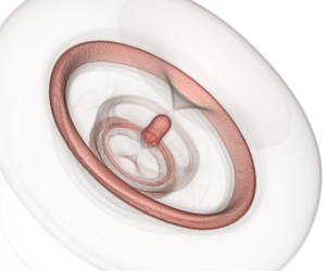
In the previous section we considered a triangular arrangement of three bubbles in both two and three dimensions (figure 9a). In the present section, our investigation is extended to alternative configurations of focusing arrangements in three dimensions, which share the same cross-section in the  $y=0$ plane, allowing thus for an appreciation of the effects of different extrusions in the third dimension. In three-dimensional space, a focusing configuration may also involve five bubbles in a pyramid-like arrangement (figure 9b). Another possible arrangement involves two bubbles, with the large one forming a torus (figure 9c). A configuration such as this is of course very difficult to achieve in water. Experiments of this kind are, however, conducted in either gels (with very high water content, 99.5 %–99.9 % by weight) or even in plastics/polymers, where the visualization of the phenomena takes advantage of the very high intensities emerging and utilizes non-visible light modalities. For the range of shockwaves of interest, such materials behave like liquids, to a degree that makes them indistinguishable from pure water. Casting and arranging bubble configurations of practically arbitrary complexity is fully feasible when such materials are used. The simulations for the new arrangements were carried out with 82 687 500 elements, as the domain was extended along the
  $y$ direction (such that
  $D_y/R_B=D_x/R_B=7$), in order to accommodate the additional bubbles. All other parameters were set as reported in § 2 and table 2 (case I).

Figure 9. Schematic of different focusing configurations.  $(a)$ Triangular arrangement,
  $(b)$ pyramidal arrangement,
  $(c)$ toroidal arrangement.
Animations depicting the collapse of all three configurations shown in figure 9 are available as supplementary movies 1, 2 and 3 at https://doi.org/10.1017/jfm.2020.535 for the cases of the triangular, pyramidal and toroidal arrangements, respectively. Note that in the animations, time is measured relative to the beginning of the simulations rather than following initial shock impact. It is interesting to mention that no three-dimensional instabilities are observed, as also reported for the collapse of a single bubble (Hawker & Ventikos Reference Hawker and Ventikos2012; Bempedelis & Ventikos Reference Bempedelis and Ventikos2020). Similar to the previous section, we begin the analysis from the time history of the maximum pressure in the domain (figure 10). It is instantly evident that the pyramidal and toroidal arrangements offer significantly higher levels of pressure amplification.

Figure 10. Time history (following shock impact) of the maximum pressure in the domain,  $p=1\ \textrm {GPa}$ shock-induced collapse of different arrangements of air bubbles in water.
5.1. Pyramidal arrangement
The first pressure peak in the case of the five-bubble array is related to the water hammer shock waves of the large bubbles, which occur at the same time as in the triangular array configuration (figures 11a and 12a). Subsequent rises (until  $t \simeq 840\ \textrm {ns}$) correspond to the collapse of the bubble lobes and the interaction of these waves upstream of the bubble (figures 11b and 12b). At
  $t=860\ \textrm {ns}$, a large pressure peak occurs as these waves interact at the centreline, upstream of the central bubble, which has assumed a mushroom-like shape (figures 11c and 12c). The bubble collapses shortly after, generating strong waves reaching up to
  $p \simeq 55.51\ \textrm {GPa}$ (figures 11d and 12d).

Figure 11. Volume rendering of the density gradient magnitude at different time instants following shock impact,  $p=1\ \textrm {GPa}$ shock-induced collapse of a pyramidal array of spherical air bubbles in water.
  $(a)$
$(a)$ $t=640\ \textrm {ns}$,
  $(b)$
$(b)$ $t=740\ \textrm {ns}$,
  $(c)$
$(c)$ $t=840\ \textrm {ns}$,
  $(d)$
$(d)$ $t=940\ \textrm {ns}$.

Figure 12. Bubble interfaces and pressure contours on the  $y=0$ plane at different time instants following shock impact,
  $p=1\ \textrm {GPa}$ shock-induced collapse of a pyramidal array of spherical air bubbles in water.
  $(a)$
$(a)$ $t=640\ \textrm {ns}$,
  $(b)$
$(b)$ $t=740\ \textrm {ns}$,
  $(c)$
$(c)$ $t=840\ \textrm {ns}$,
  $(d)$
$(d)$ $t=940\ \textrm {ns}$.
5.2. Toroidal arrangement
The collapse of the toroidal bubble occurs much later compared with the large spherical bubbles (at  $t=690\ \textrm {ns}$). In fact, the time required for the jet to impact the far bubble wall is similar to the (two-dimensional) case of cylindrical bubbles. Following the main jet impact, the torus is split in two rings (figure 13a), and later in three rings, following the collapse of the inner one (figure 13b). The waves from the collapse of the inner ring strengthen as they converge towards the centreline, where they interact (upstream of the small bubble) at
  $t=950\ \textrm {ns}$ (figure 13c). Shortly after, the central bubble collapses producing very large pressures, reaching
  $p \simeq 140.76\ \textrm {GPa}$ (figure 13d).

Figure 13. Volume rendering of the density gradient magnitude at different time instants following shock impact,  $p=1\ \textrm {GPa}$ shock-induced collapse of a pair of toroidal and spherical air bubbles in water.
  $(a)$
$(a)$ $t=760\ \textrm {ns}$,
  $(b)$
$(b)$ $t=890\ \textrm {ns}$,
  $(c)$
$(c)$ $t=950\ \textrm {ns}$,
  $(d)$
$(d)$ $t=1040\ \textrm {ns}$.
6. Conclusions
In the present work we computationally investigated the energy concentration that occurs during the shock-induced collapse of a focusing triangular three-bubble array. The collapse of such a configuration was studied for the first time considering spherical bubbles, and the dynamics were shown to be very different in comparison to two-dimensional cavities. Different interbubble distances were also considered, and their effect on achieved pressure levels was shown to be very important for three-dimensional configurations: their character could change completely, from strongly focusing energy through chain reactions to lessening the magnitude of the produced waves.
Experimentation with alternative focusing configurations in three-dimensional space showed potential for achieving substantially enhanced levels of pressure amplification (more than 100 times the strength of the incident shock in the case of the torus/sphere pair), and that different forms of extrusion significantly affect the focusing levels. These results are of relevance to fields such as energy generation and sensitization of explosives.
Future work includes investigations on the effects of parameters that were not part of this study, such as the strength of the incident shock and the bubble size ratio. Having in mind applications of acoustic cavitation, and in particular biomedical ones, we note that even though lithotripter-generated shockwaves are weaker compared with the conditions of this study, bubbles could be impacted by shocks of such strength following the collapse of bubbles in their vicinity. Furthermore, the mechanisms under discussion (pertaining to the collapse of the array in a likely synergistic manner) are also present when different incident shock strengths are considered (see appendix A.2). Moreover, the present study can be extended to arrays involving a larger number of bubbles or other geometrical arrangements.
Acknowledgements
This work was carried out in the framework of the HAoS project, which has received funding from the European Union Horizon 2020 Research and Innovation programme, grant agreement no. 675676. The authors would like to express their gratitude to Professors J. Glimm and X. Li of Stony Brook University for the use of their front tracking framework.
Declaration of interests
The authors report no conflict of interest.
Supplementary movies
Supplementary movies are available at https://doi.org/10.1017/jfm.2020.535.
Appendix A
In this appendix we examine and demonstrate the relevance of the discussion and the mechanisms described in the main body of the paper to configurations involving arbitrary arrays (in terms of spatial arrangement and bubble sizes) and different conditions.
A.1. Arbitrary arrays
The ideal arrangement of bubbles (in the case of artificially generated arrays) results in a likely enhancement of the amplification levels compared with configurations that are not perfectly symmetric (i.e. in the case of arrays formed by natural means). However, the mechanisms that govern the collapse are the same. To demonstrate this, we conducted a simulation considering a focusing triangular array of three cylindrical air bubbles of three different sizes placed randomly within the computational domain. The initial radii and centres  $\boldsymbol {x}_{\boldsymbol {c}}$ of the bubbles (from left to right as illustrated in figure 1) are shown in table 3. All other parameters were set as described in § 2.
Table 3. Bubble sizes and centres for the case of the random array.

The collapse of the array is visualized in figure 14. It is clear that the mechanisms under discussion (i.e. the involvement of the shocks generated at the collapse of the upstream bubbles to the collapse of the central one) are present in the arbitrary configuration as well. With respect to the pressure, the predicted peak was  $p \simeq 7.85\ \textrm {GPa}$, also confirming the presence of focusing effects.

Figure 14. Bubble interfaces and pressure contours at different time instants following shock impact,  $p=1\ \textrm {GPa}$ shock-induced collapse of a randomly arranged triangular array of cylindrical air bubbles in water.
  $(a)$
$(a)$ $t=50\ \textrm {ns}$,
  $(b)$
$(b)$ $t=700\ \textrm {ns}$,
  $(c)$
$(c)$ $t=840\ \textrm {ns}$,
  $(d)$
$(d)$ $t=970\ \textrm {ns}$.
A.2. Incident shock strength (weak shocks)
A simulation involving a focusing triangular array of three cylindrical air bubbles (with geometrical properties corresponding to those described in table 2, case I) with different incident shock strength was also conducted, in order to show that the described mechanisms are not particular to the conditions considered in the main body of the paper. The intensities in the case that follows are more akin to histotripsy applications: the incident shock strength was  $p=100\ \textrm {MPa}$, corresponding to a Mach number
  $M \simeq 1.05$. Note that in this case, the interaction of waves at the lateral boundaries (through the enforcement of periodic conditions) affects the dynamics and intensity of the collapse (compared with a free field scenario): the post-shock liquid pressure relaxes prior to the collapse of the bubbles, rendering it thus weaker.
The collapse is visualized in figure 15. The synergistic contribution of the shocks generated at the collapse of the upstream bubbles to the collapse of the central one may again be observed. The presence of focusing effects is also reflected in the pressure; a more than twofold increase in the peak compared with the collapse of a single bubble (in a simulation with similar parameters) is predicted.

Figure 15. Bubble interfaces and pressure contours at different time instants following shock impact,  $p=100\ \textrm {MPa}$ shock-induced collapse of a triangular array of cylindrical air bubbles in water.
  $(a)$
$(a)$ $t=450\ \textrm {ns}$,
  $(b)$
$(b)$ $t=3960\ \textrm {ns}$.


