


1 Introduction
The flow past a circular cylinder is a classical problem in fluid dynamics and has been extensively researched (Strouhal Reference Strouhal1878; Williamson Reference Williamson1996c). The study of flow around a circular cylinder has proved to be helpful in understanding a broad class of flows, as it comprises several complications such as shear layer instability, adverse pressure gradient, flow separation, vortex shedding, etc. Studies also focus on active and passive flow control mechanisms to reduce the structural vibrations and the increase in drag that occurs as a result of vortex shedding. The passive flow control strategies include the use of a splitter plate, surface modifications, etc.; while the active control strategies consist of periodic blowing and suction, distributed forcing, etc. (Choi, Jeon & Kim Reference Choi, Jeon and Kim2008). A recent experimental study on flow around hydrofoils with varying hydrophobicity for the range of Reynolds numbers 6500–30 800 by Sooraj, Jain & Agrawal (Reference Sooraj, Jain and Agrawal2019) reported approximately 40 % reduction in the drag coefficient when a superhydrophobic hydrofoil is used at  $15^{\circ }$ angle of attack. This provided the motivation for examining the effect of superhydrophobicity on other shapes: here we study the flow around a circular cylinder with surface modification.
A surface can be made superhydrophobic by adding nano/micro-textures on a hydrophobic material. Superhydrophobic materials are widely used for viscous drag reduction, self-cleaning, anticorrosion and anti-icing because of their ability to retain air pockets while immersed in water (Rothstein Reference Rothstein2010). An air–water interface is formed between the peaks in the surface roughness of a superhydrophobic surface as a result of inhibiting the movement of water into the space between the peaks. This is known as the Cassie state. If water penetrates fully into the space between the peaks, the flow transits to the Wenzel state.
For an internal flow in a channel, the effect of superhydrophobic surfaces has been experimentally studied by many researchers. Laminar channel flow using a superhydrophobic surface has been studied by Ou, Perot & Rothstein (Reference Ou, Perot and Rothstein2004) and Ou & Rothstein (Reference Ou and Rothstein2005). They noticed that the reduction in the drag and slip length increases with an increase in the percentage of shear-free air–water interface. The turbulent channel flow with walls made of superhydrophobic surfaces has also been studied experimentally. Daniello, Waterhouse & Rothstein (Reference Daniello, Waterhouse and Rothstein2009) observed an almost 50 % drag reduction in the turbulent regime. They suggested that the drag reduction increases with Reynolds number before attaining an asymptotic value. Aljallis et al. (Reference Aljallis, Sarshar, Datla, Sikka, Jones and Choi2013) experimentally studied the effect of a superhydrophobic flat plate in a turbulent channel flow and observed a reduction in the skin friction drag in turbulent boundary layer flows.
For an external flow across a hydrophobic cylinder, You & Moin (Reference You and Moin2007) presented a numerical study, using direct numerical simulations (DNS) and large eddy simulations (LES), for Reynolds numbers of 300 and 3900. They observed that a hydrophobic treatment on a microscale circular cylinder leads to reduction in the mean drag and the root-mean-square (r.m.s.) lift coefficient values. Also, the drag reduction in the laminar vortex shedding regime is mainly through the reduction in skin friction, while the reduction in the shear layer transition regime is due to a delay in separation. Legendre, Lauga & Magnaudet (Reference Legendre, Lauga and Magnaudet2009) studied the effect of partial slip on the wake of a circular cylinder for the Reynolds-number range of 5–800 using DNS, and reported that the shedding frequency increases with an increase in the slip at the cylinder surface. They also reported reductions in vortex intensity near the wake, the drag and the lift values, and a delay in the onset of vortex shedding in the presence of slip.
Furthermore, Muralidhar et al. (Reference Muralidhar, Ferrer, Daniello and Rothstein2011) and Kim, Kim & Park (Reference Kim, Kim and Park2015) reported that, for flow around a cylinder, surface modifications like superhydrophobicity can delay the onset of vortex shedding and reduce the drag. Superhydrophobic surfaces enhance the vortex shedding frequency and lead to an early vortex rollup. Muralidhar et al. (Reference Muralidhar, Ferrer, Daniello and Rothstein2011) experimentally studied the effect of partial-slip condition using different superhydrophobic surfaces for Reynolds numbers up to 10 000. They noticed that the flow behaviour depends upon the alignment of ridges on the superhydrophobic surface; the shedding frequency also increases compared to a smooth circular cylinder. The ridges aligned in the flow direction exhibit higher shedding frequency compared to those aligned in the normal direction. They also noticed a delayed onset of vortex shedding and an elongation of the recirculation bubble for a cylinder with a superhydrophobic surface. Daniello et al. (Reference Daniello, Muralidhar, Carron, Greene and Rothstein2013) studied the effect of superhydrophobicity on vortex-induced motion of a circular cylinder for Reynolds-number range 1300–2300. They found that slip decreases the r.m.s. lift and the amplitude of the oscillating cylinder. They also observed that slip increases the dimensions (length and width) of the recirculation bubble while decreasing the intensity of shed vortices and the lift coefficient.
Brennan et al. (Reference Brennan, Fairhurst, Morris, McHale and Newton2014) conducted experiments on a circular cylinder coated with hydrophobized sand of size varying from 50 to  $710~\unicode[STIX]{x03BC}\text{m}$ for a Reynolds-number range of
  $(1{-}4)\times 10^{4}$. They observed a drag reduction of 28 % for hydrophobic sand-coated cylinder in the Cassie–Baxter state compared to the Wenzel state. The cause of drag reduction was attributed to both the thickness of the plastron and the protrusion height of the features. Kim et al. (Reference Kim, Kim and Park2015) performed experiments on a circular cylinder coated with roughened Teflon and another spray-coated (with hydrophobic nanoparticles) cylinder. They examined the effect of gas fraction, size of particles and direction of surface slip on the cylinder wake for Reynolds numbers
  $(7{-}23)\times 10^{3}$. They observed a delay in separation and an early rolling-up of vortices, suggesting the enhancement of turbulence in the flow around the circular cylinder and along the shear layer to be the reasons for the latter observation.
The wake of a circular cylinder below  $Re<20\,000$ is very interesting since it consists of five different flow regimes where the base suction coefficient varies nonlinearly (Williamson Reference Williamson1996c). While some studies on superhydrophobic cylinders are available in the literature, a systematic study on the effect of a superhydrophobic surface in different flow regimes is not available. Therefore, it is still not clear which flow regime is affected more when superhydrophobicity is imposed on the cylinder. The effect of superhydrophobicity on the variations in the velocity recovery, Reynolds shear stress and drag coefficient values for different flow regimes are not available in the literature. The changes in the wake dynamics when low base suction coefficient and superhydrophobicity act together have not been given enough attention in previous studies.
Therefore, the present study focuses on the following: (i) the effect of superhydrophobic surface on the onset of vortex shedding, (ii) the effect of a superhydrophobic surface on various flow regimes (as classified by Williamson (Reference Williamson1996c)) using wake parameters and force coefficient estimation, and (iii) the variation in coherent structures upon employing a superhydrophobic surface.
2 Experimental set-up
The experiments are conducted in a closed-loop water tunnel with a working section of  $400~\text{mm}\times 400~\text{mm}$ cross-section and a length of 1500 mm using particle image velocimetry (PIV). A detailed description of the experimental set-up is provided in Sooraj & Agrawal (Reference Sooraj and Agrawal2018) and Khan et al. (Reference Khan, Sooraj, Sharma and Agrawal2018). The velocity of the flow is varied from 0.005 to
  $0.5~\text{m}~\text{s}^{-1}$ and the turbulent intensity of the flow is found to be less than 1.4 %.
A schematic of the PIV system employed for the present work is shown in figure 1. Nd:YAG double-pulse lasers (Beamtech, China; wavelength 532 nm, energy  $200~\text{mJ}~\text{pulse}^{-1}$, repetition rate 15 Hz) are used to illuminate seeding particles (glass particles of size
  $8{-}10~\unicode[STIX]{x03BC}\text{m}$). The images are captured using a charge-coupled device (CCD) camera (PCO Pixefly, Germany; image size 1392 pixels
  $\times$ 1024 pixels) at a frequency of 5 Hz. Based on the flow speed, the time delay for a pair of images is varied from 1.5 to 70 ms.

Figure 1. Schematic of the experimental set-up.
Circular cylinders of diameters ( $D$) 10 and 25 mm with a span of 400 mm are employed in the measurements. The circular cylinders employed are made of acrylic; acrylic, being transparent, allows imaging on both sides of the cylinder. Two circular cylinders with diameters 10 and 25 mm, respectively, are spray-coated with a superhydrophobic paint (‘Ultra Ever Dry’; UltraTech International Inc., Florida, USA). This commercial paint uses proprietary omniphobic technology to coat an object and creates a surface chemistry and texture with a reduced surface energy. The paint provides a superhydrophobic and an oleophobic coating that repels most water-based and some oil-based liquids. A detailed mechanical and chemical durability study on this paint is available in Wang et al. (Reference Wang, Yang, Zhu, Li, Sheng, Hu and Yang2016). The thickness of the superhydrophobic paint coating is approximately 0.05 mm.
The blockage ratio is much less than 10 % and therefore no correction is performed on the measured data (Boutilier & Yarusevych Reference Boutilier and Yarusevych2012). A total of 1500 image pairs have been obtained for each case and it is found that the number of frames is sufficient for the convergence of the r.m.s. velocity value. PIVlab 1.35 (MATLAB-based PIV software) is used to analyse the images captured (Thielicke & Stamhuis Reference Thielicke and Stamhuis2014). A cross-correlation method is used as an interrogation method in the MATLAB package. An interrogation window size of 32 pixels  $\times$ 32 pixels with 50 % overlap is used to analyse the images. A total of
  $63\times 86$ velocity vectors are obtained for each frame of size
  $7.67~\text{cm}\times 5.63~\text{cm}$. The Stokes number (
 $St$) value based on particle diameter and flow speed is found to be of the order of
  $10^{-4}$ to
  $10^{-6}$. Therefore, the seeding particles are expected to closely trace the fluid motion, with an error of less than 1 % (Pescini et al. Reference Pescini, Francioso, De Giorgi and Ficarella2015).
A detailed uncertainty analysis is performed for the experiments conducted as described in Sooraj, Agrawal & Sharma (Reference Sooraj, Agrawal and Sharma2018). The uncertainty with equipment includes the uncertainties associated with calibration, scaling magnification, time accuracy and that with CCD. The particle lag can be determined using Stokes’ drag law. Random error sampling theory has been used to find the random measurement error in the sampling data, from which the uncertainty associated with the sampling is estimated. The uncertainty in the processing data is estimated by considering the size of a particle, number of particles in a window, particle image displacement, the effect of background noise and effect of displacement gradients. The standard uncertainty propagation method is employed to obtain the combined uncertainty in the PIV measurements. The maximum uncertainty in velocity measurement is estimated to be  $\pm 2.3\,\%$, while that in the drag coefficient is estimated as
  $\pm 4.2\,\%$. The modified wake survey method (3.1) is used to obtain the value of the drag coefficient.
3 Results
In this section, we first present contact-angle measurements and roughness estimation in order to characterize the acrylic and the superhydrophobic painted surfaces employed. The flow behaviour over these surfaces is examined mainly using instantaneous vorticity fields, time-averaged velocity profile, variation in the centreline velocity, variation in the Reynolds shear stress (RSS), variation in the turbulent kinetic energy (TKE) and examination of the coherent structures in the wake. The drag coefficient is also calculated for all the cases. The flow behaviour over a wide range of Reynolds numbers ( $Re=\unicode[STIX]{x1D70C}u_{\infty }D/\unicode[STIX]{x1D707}$, where
  $D$ is the diameter of the cylinder and
  $u_{\infty }$ is the free-stream velocity) is studied (
 $Re=45$, 50, 64, 70, 110, 150, 175, 198, 220, 250, 270, 300, 550, 860, 1100, 1500, 2000, 3000, 5000, 7000, 10 000, 14 000 and 15 500) in order to cover various flow regimes.
The engineering parameters calculated have been non-dimensionalized as  $X=x/D$,
  $Y=y/D$ and
  $U=u/u_{\infty }$, where
  $D$ is the cylinder diameter,
  $x$ and
  $y$, respectively, are the streamwise and transverse coordinates, and
  $u$ is the velocity in the streamwise direction. TKE and RSS are calculated using the expressions
  $\text{TKE}=(\overline{u^{\prime 2}}+\overline{v^{\prime 2}})/(2u_{\infty }^{2})$ and
  $\text{RSS}=\overline{u^{\prime }v^{\prime }}/u_{\infty }^{2}$, where
  $u^{\prime }$ and
  $v^{\prime }$, respectively, are the fluctuations in the streamwise and transverse velocity components, and the overbars denote averages with respect to time. The smooth circle and the superhydrophobic painted surfaces are represented by filled and empty circles, respectively, in the figures.
3.1 Contact-angle measurement and roughness estimation
A detailed explanation of the contact-angle measurement and the surface roughness characteristics is given in Sooraj et al. (Reference Sooraj, Jain and Agrawal2019). A high-speed camera (Motion Pro X series, Redlake) is used to obtain the contact angles of acrylic and superhydrophobic painted surfaces. The tangent method is employed to measure the contact angle of the droplet on these surfaces. It is found that the superhydrophobic surface has a contact angle of  $152^{\circ }$ with an advancing and receding angle of
  $155^{\circ }$ and
  $144^{\circ }$, respectively. Wang et al. (Reference Wang, Yang, Zhu, Li, Sheng, Hu and Yang2016), Castagna, Mazellier & Kourta (Reference Castagna, Mazellier and Kourta2018) and Sooraj et al. (Reference Sooraj, Jain and Agrawal2019) conducted exhaustive measurements on the longevity of the same paint used for the present study. This investigation suggested that there is no Cassie to Wenzel transition in the present experiments. Details about the two surfaces employed in this work are presented in table 1.
The roughness of the hydrophobic surface is estimated using an Alicona infinite focus microscope (figure 2). The three important parameters that characterize the roughness, estimated from the 250 linear profiles taken over a sampling length of  $178~\unicode[STIX]{x03BC}\text{m}$, are arithmetic roughness (
 $R_{a}$) of
  $14.85~\unicode[STIX]{x03BC}\text{m}$, average r.m.s. height (
 $R_{rms}$) of
  $17.52~\unicode[STIX]{x03BC}\text{m}$ with a skewness of 0.47, and mean peak-to-trough roughness height (
 $R_{PT}$) of
  $28.16~\unicode[STIX]{x03BC}\text{m}$.

Figure 2. Three-dimensional contour of the superhydrophobic surface profile obtained from the Alicona infinite focus microscope.
Table 1. Contact-angle measurements for different surface types.

3.2 Variation in time-averaged centreline velocity
The time-averaged centreline velocity along the streamwise direction is shown in figure 3. The velocity is negative in the recirculation region and attains a positive value as the entrainment of fluid from the surroundings occurs further downstream. The cross-over point is the saddle point, based on which the recirculation length is calculated. Since the onset of vortex shedding is delayed for the superhydrophobic cylinder because of the partial-slip boundary conditions (Muralidhar et al. Reference Muralidhar, Ferrer, Daniello and Rothstein2011), the recovery of velocity is slower than that of a smooth cylinder, as shown in figure 3(a). The recirculation length is almost the same for the smooth cylinder and the superhydrophobic cylinder at  $Re=150$ (figure 3b). However, the velocity recovery is faster for the superhydrophobic cylinder as the downstream distance increases.

Figure 3. Variation of time-averaged centreline velocity for superhydrophobic, smooth and rough hydrophilic cylinders at (a)  $Re=64$, (b)
  $Re=150$, (c)
  $Re=220$, (d)
  $Re=300$, (e)
  $Re=860$ and (f)
  $Re=3000$.
The superhydrophobic cylinder has comparatively smaller recirculation length beyond  $Re=220$. The percentage reduction in the recirculation length for the superhydrophobic cylinder increases from 14.6 % to 35.4 % as the Reynolds number increases from 220 to 300. Further increase in the Reynolds number to 860 constitutes a difference of
  $1.78D$ between the smooth and the superhydrophobic cylinders (figure 3e). The percentage reduction in the recirculation length reduces as the Reynolds number increases to 3000 for the superhydrophobic cylinder compared to the smooth cylinder, as is evident from figure 3(f). The result presented in this section shows that the superhydrophobic cylinder enhances the momentum gain compared to the smooth cylinder. Lin, Towfighi & Rockwell (Reference Lin, Towfighi and Rockwell1995) also showed that the recirculation length at
  $Re=1000$ is large compared to that at
  $Re=5000$ and 10 000 for a smooth circular cylinder. The basic reason behind the large separation bubble in the Reynolds-number regime 300–1000 is reduction in the base suction coefficient. The base suction coefficient become minimum at
  $Re\sim 1000$, which leads to this behaviour (Unal & Rockwell Reference Unal and Rockwell1988; Lin et al. Reference Lin, Towfighi and Rockwell1995).
The effect of roughness on the flow has been separately studied by Lee, Kim & Park (Reference Lee, Kim and Park2018) for a NACA 0012 airfoil, since a superhydrophobic surface is rough in nature. They found that there is little difference in the flow profile because of the rough surface with average roughness height of  $12~\unicode[STIX]{x03BC}\text{m}$. Similar tests have been conducted for the present study as well. Here, the superhydrophobic cylinder is made wet using 40 % aqueous ethanol (surfactant) for 10 min and it is immediately transferred to the water tunnel and the experiments are conducted. This maintains the roughness level while only affecting the hydrophobicity of the surface. As per another study by Wang et al. (Reference Wang, Yang, Zhu, Li, Sheng, Hu and Yang2016), the surface will retain its hydrophilicity till it is wet (the surface regains its superhydrophobic property only after it is completely dried). The centreline velocity obtained for the rough hydrophilic surface is shown in figure 3. There is an inappreciable difference in the centreline velocity profile between the smooth and rough hydrophilic cylinders. A similar behaviour is noted for drag coefficient, as discussed later through figure 9. Therefore, the difference in the centreline velocity profiles between superhydrophobic and smooth cylinders is not due to roughness; rather, it is due to the hydrophobicity of the surface.
3.3 Variation in instantaneous flow field
The instantaneous vorticity field superimposed with streamlines for a superhydrophobic and a smooth circular cylinder is shown in figure 4. The smooth cylinder starts shedding as the Reynolds number reaches 48, while the superhydrophobic cylinder is not exhibiting vortex shedding even at  $Re=64$, as is evident from figure 4(a). The critical Reynolds number for a superhydrophobic cylinder is found to lie between 64 and 72. Even though the onset of vortex shedding is delayed, the rolling-up of shear layer occurs closer to the superhydrophobic cylinder as compared to the smooth cylinder when the Reynolds number increases beyond the critical Reynolds-number value. This is further evident while tracking the location of the saddle point with the help of streamlines.

Figure 4. Instantaneous vorticity field superimposed with streamlines for  $Re=64$. The empty cylinder (a) corresponds to the superhydrophobic cylinder while the filled cylinder (b) is for the smooth cylinder.
The early rolling-up of vortices is observed in the wake of a superhydrophobic circular cylinder and the effect is much more profound at  $Re=860$. The shear layer elongates and moves further downstream before rolling up, which is evident from the flow field of the smooth cylinder. The difference between the streamwise location at which the shear layer interaction occurs reduces as the Reynolds number increases to 3000. The behaviour at the shear layer interactions is further confirmed by the time-averaged velocity data shown in figure 5, discussed in detail in the next section. The shear layer length (
 $L_{s}/D$) is taken as the length from the centre of the cylinder to 30 % of the maximum vorticity value in the wake of the time-averaged vorticity data.

Figure 5. Time-averaged velocity profiles at various streamwise locations for (a)  $Re=64$, (b)
  $Re=150$, (c)
  $Re=220$, (d)
  $Re=300$, (e)
  $Re=860$, (f)
  $Re=3000$ and (g)
  $Re=15\,500$. Note that the columns correspond to different streamwise locations (
 $X=0.5$, 1, 2 and 3), with each panel presenting a comparison between the superhydrophobic and smooth cylinders.
3.4 Variation in time-averaged velocity profile
The velocity profiles at different streamwise locations are plotted along the lateral direction for various Reynolds numbers in figure 5. The velocity profiles of figure 5(a–c) show  $u>1$ in the outer wake region at
  $X=1$. This indicates the presence of a shear layer. The presence of
  $u>1$ in figure 5(c) at
  $X=2$ explains the presence of a longer shear layer for the smooth cylinder. At
  $Re=300$, the near wake is wider with a blunt profile for the streamwise velocity at
  $X=0.5$ (figure 5d). The profile smoothes at
  $X=1$ with a relatively quicker gain of momentum for the superhydrophobic cylinder as compared to the smooth cylinder. The presence of
  $u>1$ till a larger axial distance for the smooth cylinder hints at a longer shear layer (figure 5d). The shear layer for the superhydrophobic cylinder is shorter, quantified and presented later in figure 11. The difference in the velocity profiles is more prevalent at
  $Re=860$ (figure 5e). The bluntness of the velocity profile persists till
  $X=1$ for both the cylinders. At
  $X=2$ it persists for the smooth cylinder whereas for the superhydrophobic cylinder the flow quickly gains momentum and smoothes its profile. This gain in momentum is indicative of a stronger lateral mixing of fluid for the superhydrophobic cylinder. The superhydrophobic cylinder is expected to have a smaller value of drag coefficient, as confirmed later through figure 9. The difference between the deficit at the centreline for the two cases is greater at
  $X=3$ for
  $Re=860$ as compared to
  $Re=300$.
The bluntness of the velocity profile at  $X=0.5$ is observed till
  $Re=1500$. But owing to the dominant inertia in the flow, the relative difference between the two types of cylinders diminishes. At
  $Re=3000$ the deficit peaks differ at
  $X=2$ (figure 5f), whereas the difference is obvious at an axial distance of
  $X=1$ at
  $Re=15\,500$ (figure 5g). These existing differences hint at the effect of superhydrophobicity even when the inertia is dominant in the flow. The differences in the deficit are less at axial locations
  $X\geqslant 2$ for
  $Re=3000$ and 15 500 as compared to
  $Re<1000$.
3.5 Variation in Reynolds shear stress
The variations in RSS with superhydrophobic and smooth cylinders for various Reynolds numbers are shown in figure 6. The superhydrophobic painted cylinder exhibits comparatively smaller values of RSS since the fluctuations are very much less along both the streamwise and the lateral directions at  $Re=64$ (figure 6a). Although the smooth cylinder shows higher RSS compared to the superhydrophobic cylinder, the values are negligibly small. The RSS value is higher for the superhydrophobic cylinder for
  $Re>64$, as shown in figure 6(b–f). Also, the position of the maxima of the RSS value is relatively closer to the superhydrophobic painted circular cylinder as compared to the smooth cylinder.

Figure 6. The RSS contours for (a)  $Re=64$, (b)
  $Re=150$, (c)
  $Re=220$, (d)
  $Re=300$, (e)
  $Re=860$ and (f)
  $Re=3000$. The empty cylinder (left column) corresponds to the superhydrophobic cylinder while the filled cylinder (right column) is for the smooth cylinder.
There is approximately 18 % reduction in the peak RSS value for the smooth cylinder while the reduction is 27 % for the superhydrophobic cylinder when the Reynolds number increases from 220 to 300. Prasad & Williamson (Reference Prasad and Williamson1997) observed a reduction in the Reynolds stresses when the Reynolds number increases from 220 to 260. An increase of 36 % and 47 % in the peak RSS value is observed for the superhydrophobic cylinder compared to the smooth cylinder at Reynolds numbers 220 and 300, respectively (figure 6c,d). Further, the peak RSS value is comparatively larger for the superhydrophobic cylinder when the Reynolds number increases from 220 to 300. Therefore, it can be concluded that the shear layer and the wake interaction are higher for the superhydrophobic cylinder. The increase in the peak RSS value as the Reynolds number increases from 300 to 860 is 154 % for the smooth cylinder, while it is 204 % for the superhydrophobic cylinder (figure 6e). As the Reynolds number increases to 3000, there is a reduction of 14 % in the RSS maximum value of the smooth cylinder compared to the superhydrophobic cylinder (figure 6f).
3.6 Variation in turbulent kinetic energy
Figure 7 shows the variation in the TKE along the cylinder centreline for various Reynolds numbers. The peak value of TKE is observed near the saddle point where the positive and negative shear layer interacts and maximum fluctuation occurs. The fluctuations are relatively small at  $Re=64$ (figure 7a). Although the peaks are at almost the same streamwise locations for the superhydrophobic and the smooth cylinders at Reynolds numbers 150 and 220, the fluctuations are stronger in the superhydrophobic case (figure 7b,c). The maxima of the TKE value for the superhydrophobic cylinder at Reynolds numbers 150 and 220 is almost
  $0.16D$ prior to the maxima obtained for the smooth cylinder along the centreline. As the Reynolds number increases to 300, the distance between the two peaks of TKE values for the smooth and the superhydrophobic cylinder, respectively, increases to
  $0.64D$ (figure 7d).

Figure 7. Variation in centreline TKE for the superhydrophobic and the smooth cylinders at (a)  $Re=64$, (b)
  $Re=150$, (c)
  $Re=220$, (d)
  $Re=300$, (e)
  $Re=860$ and (f)
  $Re=3000$.
A maximum streamwise distance of  $0.69D$ between the peaks of the TKE values for the smooth and the superhydrophobic cylinders is observed at
  $Re=860$. Also, there is a reduction of 31 % in the peak TKE value at
  $Re=860$ for the smooth cylinder compared to the superhydrophobic cylinder. Unal & Rockwell (Reference Unal and Rockwell1988) suggested that the fine-scale three-dimensionality becomes increasingly disordered when the Reynolds number increases from 260 to 1000, which leads to an increase in the recirculation length and thereby delays the interaction between the shear layers. Therefore, the maximum fluctuations occur farther downstream for the smooth cylinder at Reynolds numbers 300 and 860 (figure 7d,e). The TKE maxima obtained for the smooth cylinder is 2.8 % less than that obtained for the superhydrophobic cylinder at
  $Re=3000$ (figure 7f). This implies that the difference in the fluctuation decreases as the Reynolds number increases to 3000.
3.7 Variation in drag coefficient
The mean drag coefficient ( $C_{D}$) is estimated using the modified wake survey method proposed by Bohl & Koochesfahani (Reference Bohl and Koochesfahani2009) and employed by Sooraj et al. (Reference Sooraj, Agrawal and Sharma2018, Reference Sooraj, Jain and Agrawal2019). The method solves the integral form of the streamwise momentum equation where the fluctuating velocity and pressure terms are suitably calculated and therefore appropriately accounted for even when the control surface is very close to the object. The mean drag coefficient is expressed in terms of the velocity as
 $$\begin{eqnarray}\displaystyle C_{D} & = & \displaystyle \frac{-2}{D}\int _{-H}^{+H}\left[\frac{u_{avg}}{u_{\infty }}\left(\frac{u_{avg}}{u_{\infty }}-1\right)+\unicode[STIX]{x1D700}\left(\frac{u_{avg}}{u_{\infty }}-1\right)\right.\nonumber\\ \displaystyle & & \displaystyle \left.+\,\left(\frac{u_{rms}}{u_{\infty }}\right)^{2}-\left(\frac{v_{rms}}{u_{\infty }}\right)^{2}+\frac{1}{2}\left(1-\frac{u_{0}^{2}}{u_{\infty }^{2}}\right)\right]\,\text{d}y,\end{eqnarray}$$
 where  $D$ is the diameter of the cylinder,
  $u_{avg}$ is the mean velocity of the flow field,
  $u_{\infty }$ is the free-stream velocity,
  $u_{o}$ is the outlet velocity,
  $2H$ is the lateral distance of the control surface,
  $u_{rms}$ and
  $v_{rms}$ are the fluctuating component of velocity in the streamwise and lateral directions, respectively, and
  $\unicode[STIX]{x1D700}$ is the effective velocity, which is defined as
  $\unicode[STIX]{x1D700}=(u_{\infty }+u_{o})/(2u_{\infty })$.
The values of the  $\unicode[STIX]{x2202}v_{rms}^{2}/\unicode[STIX]{x2202}y$ term is dominant in the transverse momentum equation suggesting that the assumption is valid. Bohl & Koochesfahani (Reference Bohl and Koochesfahani2009) took their measurements at
  $x/C=1$ and
  $H/C=0.3$. Kim et al. (Reference Kim, Kim and Park2015) located the control volume at
  $x/D=3.5$. They also mentioned that they could not observe much variation in the drag coefficient values beyond
  $x/d=2.5$. A sensitivity analysis is performed to identify the boundaries of the control surface. The streamwise and lateral distances are normalized using recirculation length (
 $L_{r}$) to avoid bias in the drag estimation, since the size of the recirculation bubble changes with surface modification (McClure & Yarusevych Reference McClure and Yarusevych2019). The drag coefficient values are found to be converging at
  $x/L_{r}=1.4$ and
  $y/L_{r}=0.7$ for the range of Reynolds numbers studied in this work. Sensitivity analysis results for smooth cylinder at Reynolds numbers 64, 300, 860 and 3000 are shown in figure 8. A similar sensitivity analysis is also performed for superhydrophobic and hydrophilic cylinders, and they possess a similar trend to the smooth cylinder (not shown). The value of Reynolds stress was also found to become zero towards the lateral edges of the control volume.

Figure 8. Sensitivity analysis performed along (a) streamwise and (b) lateral directions for the smooth cylinder.
The drag coefficient value obtained from the present study is compared with Wieselsberger (Reference Wieselsberger1921), Meneghini et al. (Reference Meneghini, Saltara, Siqueira and Ferrari2001), Lee et al. (Reference Lee, Lim, Han and Lee2005), Dong et al. (Reference Dong, Karniadakis, Ekmekci and Rockwell2006), Harichandan & Roy (Reference Harichandan and Roy2010), Ouvrard et al. (Reference Ouvrard, Koobus, Dervieux and Salvetti2010), Wornom et al. (Reference Wornom, Ouvrard, Salvetti, Koobus and Dervieux2011), Kim et al. (Reference Kim, Kim and Park2015) and Zhou et al. (Reference Zhou, Wang, Guo, Zheng and Tan2015). The values in the literature vary from 1.63 to 1.12 for the range of Reynolds numbers 45–15 500 and the values estimated from the present study vary from 1.61 to 1.115, which are therefore in very good agreement with the reported values (not shown).
Figure 9 shows the variation of the drag coefficient with Reynolds number for the superhydrophobic and the smooth cylinders. The drag coefficient value estimated for the superhydrophobic cylinder at  $Re=45$ is lower since both types of cylinders are in the laminar steady regime. At
  $Re=64$, the superhydrophobic cylinder is in the laminar steady regime whereas the flow around a smooth cylinder is in the laminar vortex shedding regime. Owing to the difference in the wake dynamics, the estimated drag coefficient at
  $Re=64$ is higher for the superhydrophobic cylinder. For the flow around the superhydrophobic cylinder in the laminar vortex shedding regime
  $(Re>72)$, a changeover occurs and the estimated drag coefficients are found to be lower compared to those for the smooth cylinder. There is a slight reduction of 5 % in the drag coefficient values for the superhydrophobic cylinder in the laminar vortex shedding regime and the wake transition regime (WTR) compared to the smooth cylinder. The difference in the drag coefficient values between the smooth and the superhydrophobic cylinders increases in the ‘increasing disorder in the fine-scale three-dimensionalities regime’ (IDFTR). The maximum reduction of 15 % in the drag coefficient value occurs at
  $Re=860$. The difference in the value of the drag coefficient between the smooth and the superhydrophobic cylinders reduces as the Reynolds number increases to 3000, which is in the ‘shear layer transition regime’ (SLTR). There is a negligible variation in the drag coefficient between the rough hydrophilic and smooth cylinders for the range of Reynolds numbers studied, again suggesting that the difference in the value of the drag coefficient is due to different surface hydrophobicities rather than to a difference in their surface roughness. The various flow regimes shown in figure 9 are further discussed in § 4.
Legendre et al. (Reference Legendre, Lauga and Magnaudet2009) studied the effect of slip on the cylinder wake. The present result matches well with the observations of Legendre et al. (Reference Legendre, Lauga and Magnaudet2009) at  $Kn\approx 0.2$ (
 $Kn=\unicode[STIX]{x1D706}/a$, where
  $\unicode[STIX]{x1D706}$ is the slip length and
  $a$ is the radius of the cylinder), although we cannot deduce the value of
  $Kn$ from our measurements. However, this comparison with numerical data suggests that the slip length is approximately 2.5 mm for a cylinder diameter of 25 mm, which could lead to the difference in the value of the drag coefficient seen here. The slip length is expected to be of the order of the roughness scale of the paint; such a large value of slip length is therefore unexpected and deserves a further closer examination.

Figure 9. Variation of drag coefficient with various Reynolds numbers for the superhydrophobic, smooth and rough hydrophilic cylinders. Regimes: LSR, laminar steady regime; LVSR, laminar vortex shedding regime; WTR, wake transition regime; IDFTR, increasing disorder in the fine-scale three-dimensionalities regime; and SLTR, shear layer transition regime. Representative error bars are also shown at a few points for the cylinders.
The variation in the drag coefficient is studied in detail and the contributions of mean  $(C_{Dm})$ and fluctuating (
 $C_{Df}$) terms are shown in figure 10(a,b). The majority of the drag coefficient is contributed by the mean term for all Reynolds numbers studied in the present work. It is found that the mean and the increased fluctuations in the streamwise velocity component (
 $u_{rms}$) play an important role in the drag reduction of the superhydrophobic cylinder for all Reynolds numbers in the IDFTR. The TKE shown in figure 7 suggests that there is a considerable difference in the values of fluctuating terms between smooth and superhydrophobic cylinders in the IDFTR, which is evident from figure 10(b).

Figure 10. Variation of mean ( $C_{Dm}$) and fluctuating (
 $C_{Df}$) terms of the drag coefficient with Reynolds number.
4 Discussion
Three different aspects of the flow around a superhydrophobic cylinder are discussed in three different subsections below. First, § 4.1 discusses the effect of superhydrophobicity on the flow past a circular cylinder in various flow regimes. Then § 4.2 discusses the variation in the coherent structures when superhydrophobicity is imposed on the cylinder. The coherent structures are obtained using proper orthogonal decomposition. The flow dynamics at  $Re=860$ is discussed in detail in § 4.3, as the estimated engineering parameters of the smooth and superhydrophobic cylinders exhibit the maximum variation at this particular Reynolds number.
4.1 Effect of superhydrophobicity in the various flow regimes
The results show that significant differences occur in the wake when a superhydrophobic cylinder is used compared to a smooth cylinder. An apparent slip is generated on the superhydrophobic cylinder because of the air–water interface, which affects the flow field irrespective of the shape of the body, i.e. bluff body, streamlined body or flat plate (Muralidhar et al. Reference Muralidhar, Ferrer, Daniello and Rothstein2011; Aljallis et al. Reference Aljallis, Sarshar, Datla, Sikka, Jones and Choi2013; Lee et al. Reference Lee, Kim and Park2018). The shear layers formed on the superhydrophobic cylinder are weak since the velocity gradient values are small because of the partial slip. The weaker shear layers cause a delay in flow separation, low vortex intensity in the wake, early rolling-up of vortices, an increase in shedding frequency and a reduction in the drag coefficient values. These characteristics of the flow past a superhydrophobic cylinder have already been noted in the literature. The results obtained in the present study are in line with these flow characteristics. A detailed discussion of the results is now presented in different flow regimes.
The flow regimes are classified as per Williamson (Reference Williamson1996c) based on instantaneous flow fields. They are laminar steady regime (LSR,  $Re<49$), laminar vortex shedding regime (LVSR,
  $49<Re<190$), wake transition regime (WTR,
  $190<Re<260$), increasing disorder in the fine-scale three-dimensionalities regime (IDFTR,
  $260<Re<1000$) and shear layer transition regime (SLTR,
  $1000<Re<20\,000$).
4.1.1 Laminar steady regime
The LSR  $(Re<49)$, where two symmetrically placed vortical regions are found on both sides of the wake, is extended till
  $Re=64$ for the superhydrophobic cylinder. The onset of shedding occurs between Reynolds numbers 46 and 50 for the smooth cylinder, while the onset of vortex shedding is delayed for the superhydrophobic cylinder, which is expected to happen between Reynolds numbers 64 and 70 (figure 4a). The delay in the onset of vortex shedding was also noticed earlier by Legendre et al. (Reference Legendre, Lauga and Magnaudet2009) and Muralidhar et al. (Reference Muralidhar, Ferrer, Daniello and Rothstein2011). The major reason for this delay is the partial slip on the surface.
According to Leal (Reference Leal1989), the vorticity accumulation in the downstream region of the cylinder is the prime reason for the separated wake and the onset of vortex shedding. Therefore, for a partial-slip condition, the threshold value of vorticity accumulation to shed vortices is reached only when the Reynolds number increases (Legendre et al. Reference Legendre, Lauga and Magnaudet2009; Muralidhar et al. Reference Muralidhar, Ferrer, Daniello and Rothstein2011).
4.1.2 Laminar vortex shedding regime and wake transition regime
In the LVSR and the WTR  $(49<Re<260)$, it is found that the RSS increases (figure 6b,c) and the length of the recirculation bubble decreases (figure 3b,c) as the Reynolds number increases. The TKE value also increases considerably when the Reynolds number increases to 220 (figure 7c). The base suction pressure increases with Reynolds number in this regime (Williamson Reference Williamson1996b). The base suction pressure is mainly dependent on the shape of the body and the Reynolds number. A superhydrophobic cylinder with the same base suction coefficient as that of a smooth cylinder triggers an early rolling-up of shear layers since the length of the shear layer is comparatively small, as shown in figure 11. The vortex rollup occurs early for the superhydrophobic cylinder, which is evident from figure 4 and was also noticed by Muralidhar et al. (Reference Muralidhar, Ferrer, Daniello and Rothstein2011) and Kim et al. (Reference Kim, Kim and Park2015). Therefore, the recirculation length reduces and we observe an increase in the fluctuating velocity components because of the larger interaction of the shear layers.
The velocity deficit experienced by the smooth and the superhydrophobic cylinders until  $X=1$ for the LVSR and the WTR are almost the same (figure 5b,c). Even though the difference is small, the difference in momentum gain between the two cylinders is observed from
  $X=2$ onwards for the above-mentioned flow regimes. However, no substantial difference in the flow dynamics is found between the superhydrophobic and the smooth cylinders in these two regimes.
4.1.3 Increasing disorder in the fine-scale three-dimensionalities regime
Major differences are observed in the IDFTR  $(260<Re<1000)$. This region is known for reduction in both the base suction pressure and the two-dimensional Reynolds stresses, and an increase in the recirculation length. In the IDFTR, the momentum gain by the superhydrophobic cylinder is faster compared to that by the smooth cylinder, as shown in figure 5(d,e). The difference in the profiles is evident from
  $X=0.5$ itself. The wake thickening is also considerably reduced as the downstream distance increases for the superhydrophobic cylinder in this flow regime. The IDFTR is characterized by an increase in the shear layer length, which essentially increases the recirculation length as observed in the smooth cylinder case (figure 3d,e) compared to the WTR (figure 3c), as shown in figure 11. However, the superhydrophobic cylinder shows comparatively meagre increase in the recirculation length, as observed from figure 3(d,e). The difference in the recirculation length between the superhydrophobic and the smooth cylinders becomes maximum at
  $Re=860$.
There is a sudden drop in RSS value in the IDFTR for both the superhydrophobic and the smooth circular cylinders (figure 6d) compared to the WTR (figure 6c). However, the reduction is more evident in the smooth cylinder. The results show that the superhydrophobic cylinder induces more fluctuations in the wake. The distance of the maxima from the superhydrophobic cylinder is relatively large at  $Re=860$ (figure 6e). The maxima of RSS is observed where the streamwise and the lateral fluctuations are maximum. The RSS and TKE peaks are obtained closer to the superhydrophobic cylinder (figure 7d,e) and the values are higher than that for the smooth cylinder by approximately 50 % at
  $Re=860$ (figure 7e). The reduction in the drag coefficient is maximum as compared to other flow regimes (for the superhydrophobic cylinder compared to the smooth cylinder) in this flow regime (figure 9).
4.1.4 Shear layer transition regime
In the SLTR  $(1000<Re<20\,000)$, the recirculation length reduces and the base suction increases. This is mainly because of the developing instabilities of the separating shear layer from the sides of the body (Williamson Reference Williamson1996a). The difference in length of the shear layer and the recirculation length between the superhydrophobic and the smooth circular cylinders is reduced in this regime compared to the IDFTR (figure 11).
It can be inferred that the effect of superhydrophobicity is diminished in the SLTR compared to the IDFTR, as is evident from figure 5(f,g). The difference in the velocity deficit between the superhydrophobic and the smooth cylinders is almost the same as the Reynolds number increases to 15 500. The TKE values are found to be higher at the SLTR for the superhydrophobic cylinder, but the difference in the TKE value with the smooth cylinder is reduced.

Figure 11. Variation in shear layer length with Reynolds number for superhydrophobic and smooth cylinders.
4.2 Variation in coherent structures in the various flow regimes
Proper orthogonal decomposition (POD) is an effective method for scrutinizing the complex flows encompassing large-scale organized structures (Lumley Reference Lumley1981; Sirovich Reference Sirovich1987; Berkooz, Holmes & Lumley Reference Berkooz, Holmes and Lumley1993). The flow patterns are extracted by considering the kinetic energy and can be used to understand the dominant coherent structures from instantaneous flow fields (Lee Reference Lee2004). In the present study, we are using the snapshot method explained by Sirovich (Reference Sirovich1987), where the velocity field  $u(\boldsymbol{x})$ is expressed in terms of time
  $(t)$ as
 $$\begin{eqnarray}u(\boldsymbol{x},t)=\mathop{\sum }_{n=1}^{N}a_{n}(t)\unicode[STIX]{x1D6F7}_{n}(\boldsymbol{x}),\end{eqnarray}$$
 where bold-face  $\boldsymbol{x}$ denotes a vector quantity,
  $N$ is the number of snapshots used to obtain the POD modes,
  $a_{n}$ is the temporal coefficient and
  $\unicode[STIX]{x1D6F7}_{n}$ is the POD eigenmode. The basis function is strongly dependent on the number of snapshots, and therefore the convergence test has been conducted using the residual concept explained by Lee, Kang & Sung (Reference Lee, Kang and Sung2008). Here 1500 snapshots are used to extract different POD modes, and it is found that the convergence is obtained by using 300 snapshots. The first four POD modes are shown in the figures, since they capture most of the energy content of the flow. The energy content of the flow is shown for all the regimes examined in the study along with the POD modes where the eigenvalue of the first 20 eigenmodes are displayed. These eigenvalues represent the relative contribution of the mode to the fluctuation energy of the flow field.
The POD modes obtained at  $Re=110$ are further compared with the result obtained by Supradeepan & Roy (Reference Supradeepan and Roy2014) for
  $Re=100$, and they are found to be in good agreement with each other. Also, the coherent structures obtained at
  $Re=150$ are similar, with a slight difference in the energy content. Therefore, the Reynolds number 110 is not shown separately. The coherent structures obtained for different flow regimes are discussed in detail in the following subsections.
4.2.1 Laminar steady regime
The superhydrophobic circular cylinder is in the LSR at  $Re=64$ and the smooth cylinder is in the LVSR for this Reynolds number (figure 12). The energy content of the POD modes shown in figure 12(e) shows that the first mode carries the maximum energy of the flow for the superhydrophobic cylinder while the first three modes are important for the smooth cylinder. Mode 1 is shown in figure 12(a), where only a shear layer is observed for the superhydrophobic cylinder; hence, only a single type of dominant structure is present for this case. Being in the LVSR at this Reynolds number and the linear combination of the three modes shown in figure 12(a–c) contribute to the entire flow in the smooth cylinder case. There is no coherent structure which has considerable energy present at mode 4 for both the cylinders (figure 12d).

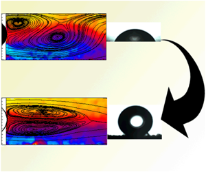
Figure 12. Decomposed streamwise coherent structures superimposed with vectors for  $Re=64$: (a) mode 1, (b) mode 2, (c) mode 3, (d) mode 4 and (e) energy content of POD modes. The empty cylinder (left column) corresponds to the superhydrophobic cylinder while the filled cylinder (right column) is for the smooth cylinder.
4.2.2 Laminar vortex shedding regime and wake transition regime
The coherent structures in the LVSR and the WTR are shown in figures 13 and 14, respectively. Both smooth and superhydrophobic cylinders produce similar structures in the dominant modes for these two regimes. The energy content data for both these cases reveal that the first four modes capture most of the flow events. Even though the fluctuations are higher in the wake of the superhydrophobic cylinder (figure 6b,c), the flow structures are unaffected in these regimes. Also, the most dominant coherent structures formed in the wake (mode 1 and mode 2) are similar in these regimes.

Figure 13. Decomposed streamwise coherent structures superimposed with vectors for  $Re=150$: (a) mode 1, (b) mode 2, (c) mode 3, (d) mode 4 and (e) energy content of POD modes. The empty cylinder (left column) corresponds to the superhydrophobic cylinder while the filled cylinder (right column) is for the smooth cylinder.

Figure 14. Decomposed streamwise coherent structures superimposed with vectors for  $Re=220$: (a) mode 1, (b) mode 2, (c) mode 3, (d) mode 4 and (e) energy content of POD modes. The empty cylinder (left column) corresponds to the superhydrophobic cylinder while the filled cylinder (right column) is for the smooth cylinder.
4.2.3 Increasing disorder in the fine-scale three-dimensionalities regime
In this regime, two different Reynolds numbers are examined based on the results explained in the previous sections. That is,  $Re=300$ and 860, where the flow behaviour changes significantly for the superhydrophobic cylinder. The coherent structures in the wake of both cylinders at
  $Re=300$ are shown in figure 15. The coherent structures are seen to form closer to the body for the superhydrophobic cylinder. Notice that the strength of the coherent structures present in the wake of the superhydrophobic cylinder are comparatively weaker than that of the smooth cylinder. The weaker coherent structures imply that weaker shear layers are formed around the superhydrophobic cylinder and the vortex intensity in the wake is very low. This is in line with the results of Legendre et al. (Reference Legendre, Lauga and Magnaudet2009) and Kim et al. (Reference Kim, Kim and Park2015).

Figure 15. Decomposed streamwise coherent structures superimposed with vectors for  $Re=300$: (a) mode 1, (b) mode 2, (c) mode 3, (d) mode 4 and (e) energy content of POD modes. The empty cylinder (left column) corresponds to the superhydrophobic cylinder while the filled cylinder (right column) is for the smooth cylinder.
At  $Re=860$, the near-wake structures are found to be different for the superhydrophobic and smooth cylinders (figure 16). More coherent structures are formed in the superhydrophobic cylinder wake, which suggests that the Strouhal number would be higher for this cylinder. Muralidhar et al. (Reference Muralidhar, Ferrer, Daniello and Rothstein2011) indeed observed a steep increase in Strouhal number in this flow regime for the superhydrophobic cylinder. The shape and strength of the coherent structures differ a lot between the superhydrophobic and the smooth cylinders. The intensity of the structures is lower for the superhydrophobic cylinder. Therefore, this case is discussed in detail in § 4.3.

Figure 16. Decomposed streamwise coherent structures superimposed with vectors for  $Re=860$: (a) mode 1, (b) mode 2, (c) mode 3, (d) mode 4 and (e) energy content of POD modes. The empty cylinder (left column) corresponds to the superhydrophobic cylinder while the filled cylinder (right column) is for the smooth cylinder.
4.2.4 Shear layer transition regime
The coherent structures in the wake of the smooth and the superhydrophobic cylinders are similar at  $Re=3000$, as shown in figure 17. However, the intensity of the structures is weaker for the superhydrophobic cylinder. The dominant energy modes (mode 1 and mode 2) are similar for both cylinders and the structures seen in the superhydrophobic cylinder wake are closer to the body.

Figure 17. Decomposed streamwise coherent structures superimposed with vectors for  $Re=3000$: (a) mode 1, (b) mode 2, (c) mode 3, (d) mode 4 and (e) energy content of POD modes. The empty cylinder (left column) corresponds to the superhydrophobic cylinder while the filled cylinder (right column) is for the smooth cylinder.
4.3 Flow dynamics at  $Re=860$

The major contrasting behaviour between the flow dynamics and the effect of superhydrophobicity is seen in the IDFTR, where the shear layer tries to elongate because of the reduction in the base suction pressure, while the partial slip on the superhydrophobic cylinder tries to generate weaker shear layers. The results show that there is only a small increase in the recirculation length compared to the WTR for a superhydrophobic cylinder. Also, the rate of increase of recirculation length in the IDFTR is lower for a superhydrophobic cylinder compared to a smooth cylinder. The results seem to be very interesting, when the flow field is closely examined. It is observed that, in order to accommodate the effect of the base suction and that of the partial slip, the vortex shedding pattern is changed in the flow.

Figure 18. Contours of  $\unicode[STIX]{x1D706}_{2}$ criterion for the superhydrophobic cylinder at
  $Re=860$. The empty cylinder (left column) corresponds to the superhydrophobic cylinder while the filled cylinder (right column) is for the smooth cylinder.
The vortex shedding patterns of successive images are thoroughly examined and the breaking of positive and negative shear layers are shown in figure 18. The  $\unicode[STIX]{x1D706}_{2}$ criterion is employed to identify the vortices in the wake (Jeong & Hussain Reference Jeong and Hussain1995), where
  $\unicode[STIX]{x1D706}_{2}$ is the discriminant for the eigenvalues of the velocity gradient matrix and is expressed as
 $$\begin{eqnarray}\unicode[STIX]{x1D706}_{2}=\left(\frac{\unicode[STIX]{x2202}u}{\unicode[STIX]{x2202}x}+\frac{\unicode[STIX]{x2202}v}{\unicode[STIX]{x2202}y}\right)^{2}-4\left(\frac{\unicode[STIX]{x2202}u}{\unicode[STIX]{x2202}x}\frac{\unicode[STIX]{x2202}v}{\unicode[STIX]{x2202}y}-\frac{\unicode[STIX]{x2202}u}{\unicode[STIX]{x2202}y}\frac{\unicode[STIX]{x2202}v}{\unicode[STIX]{x2202}x}\right).\end{eqnarray}$$
 The  $\unicode[STIX]{x1D706}_{2}$ value is negative in the swirling region; therefore, to identify the positive and negative vortices, the sign of the vortices is multiplied accordingly.
The breaking of the shear layer downstream is very interesting. Unlike the smooth cylinder, when the upper shear interacts with the lower shear layer, two vortices are shed downstream from the lower shear layer and one from the upper shear layer (figure 18a). Similarly, when the lower shear layer interacts with the upper shear layer, two vortices are shed from the upper shear layer along with a vortex from the lower shear layer (figure 18b). This constitutes a  $\text{P}+\text{S}$ vortex shedding pattern, where P stands for a pair and S stands for a single vortex, as shown in figure 18 in the case of a superhydrophobic cylinder; whereas in a smooth cylinder only a pair of vortices are shed into the wake (within the streamwise distance of
  $4D$). The affinity of the weaker shear layer, generated from the superhydrophobic cylinder, towards early rolling-up in this particular flow regime changes the vortex shedding pattern. Since the shear layers are weak, one of the shear layer breaks into two vortices (instead of one) while interacting with the opposite/counter-rotating shear layer. Because of this, more fluid entrainment occurs and therefore the maximum momentum gain is observed at Reynolds number of
  $Re=860$ and is reflected in the drag coefficient value. An increase in velocity fluctuation is observed compared to the smooth cylinder, suggesting that the interactions of the shear layer are maximum in this regime.
The SLTR shows similar behaviour as reported by Kim et al. (Reference Kim, Kim and Park2015). The engineering parameters calculated for this regime match well with their results. However, the effect of superhydrophobicity does not fade away till  $Re=15\,500$.
5 Conclusions
A particle image velocimetry-based study is conducted on superhydrophobic and smooth circular cylinders over a large range of Reynolds numbers (45–15 500). The objective of the study is to understand the effect of superhydrophobicity in various flow regimes of the circular cylinder wake, specifically when two-dimensional and three-dimensional instabilities occur. Instantaneous and time-averaged flow fields, turbulent wake parameters and coherent structures in the wake are thoroughly examined. The mean drag coefficient is obtained from the velocity fields.
The onset of vortex shedding is found to be delayed for the superhydrophobic cylinder compared to the smooth cylinder, and the shedding starts between Reynolds numbers 64 and 70. The maximum difference in the velocity deficit between these two cylinders occurs in the IDFTR. The superhydrophobic cylinder outperforms the smooth cylinder in the unsteady regime in gaining momentum downstream. Unlike the steady regime, the recirculation length is found to be smaller for the superhydrophobic cylinder in the unsteady regime. The RSS values are found to be higher for the superhydrophobic cylinder except in the steady regime. The variation in the TKE along the centreline shows that the fluctuations are maximum for the superhydrophobic cylinder in the unsteady regime. The coherent structures in the wake are identified using POD, and major differences are found in the LSR and IDFTR. In particular, the number of coherent structures increases in the wake of the superhydrophobic cylinder at  $Re=860$. The drag coefficient values for the superhydrophobic cylinder reduces compared to that for the smooth cylinder. A maximum reduction of 15 % is observed at
  $Re=860$. The IDFTR is further examined, since a drastic difference in the wake parameters is observed. This regime is known for a reduced base suction coefficient as well as an increased recirculation length. It is found that, in order to accommodate the effect of superhydrophobicity, the wake modifies the vortex shedding pattern to
  $\text{P}+\text{S}$, which is explained using the results obtained from the
  $\unicode[STIX]{x1D706}_{2}$ criterion.
The present results can pave the way to employing superhydrophobic painted cylinders in various engineering applications. A relatively large value of slip length, beyond that seen through DNS data in the literature, is suggested by these measurements in certain regimes. Choi & Kim (Reference Choi and Kim2006) reported that, by fabricating superhydrophobic surfaces that minimize the liquid–solid contact area, a nanostructured superhydrophobic surface with  $1{-}2~\unicode[STIX]{x03BC}\text{m}$ height and
  $0.5{-}1~\unicode[STIX]{x03BC}\text{m}$ pitch could produce approximately
  $20~\unicode[STIX]{x03BC}\text{m}$ slip length. This needle-like arrangement helps the liquid to flow largely over the layer of air, resulting in a large amount of effective slip length. In the present study, any non-uniformity in the superhydrophobic surface may lead to a large slip length depending upon the roughness height and pitch. Also, the comparatively large measurement error at low Reynolds numbers, evident from figure 9, could lead to deviation from the earlier simulation results. It will therefore be interesting to perform measurements near the cylinder surface, which will help in determining the slip length directly and lead to a better understanding of the flow physics responsible for the large slip length. Estimating the integral momentum length and slip length directly will therefore help in further understanding of the problem, which will be attempted in a future work.
Acknowledgements
The authors would like to acknowledge Professor R. Singh (Department of Mechanical Engineering, Indian Institute of Technology Bombay) for the Alicona infinite focus microscope measurements.
Declaration of interests
The authors report no conflict of interest.


