


1 Introduction
The design of hypersonic vehicles is beset by a number of important challenges, chief among them the accurate prediction of aerodynamic heating and efficient operation of scramjet engines where applicable. Each of these challenges is closely related to the challenge of boundary-layer stability and transition, as a turbulent boundary layer implies a higher surface heat transfer rate and improved inlet performance and fuel–air mixing in the engine. Of lesser, but still significant importance is the effect of transition on viscous drag.
Crossflow arises on a number of geometries found ubiquitously on hypersonic vehicles such as swept surfaces, axisymmetric bodies at non-zero angle of incidence or rotating axisymmetric bodies. The body geometry combined with the pressure gradient results in curved inviscid streamlines at the boundary-layer edge, where the stream-normal component of the pressure gradient serves as the centripetal force. Near the wall, the velocity is reduced but the pressure gradient is constant, resulting in a non-zero-velocity component normal to the inviscid streamlines called crossflow. A typical crossflow profile is depicted in figure 1. The crossflow profile necessarily includes an inflection point and is therefore a source of inviscid instability (Saric, Reed & White Reference Saric, Reed and White2003).
The crossflow instability manifests in the boundary layer as a wave oriented in the crossflow direction. While both the stationary and travelling varieties of these waves may be unstable, their initial amplitudes are determined independently by surface roughness and the free-stream turbulence level, respectively. As a result, while travelling waves are typically more unstable, it is often the stationary wave that dominates the transition process in low-disturbance environments such as in flight (Deyhle & Bippes Reference Deyhle and Bippes1996).

Figure 1. A typical crossflow profile calculated from a compressible Falkner–Skan–Cooke solution. Profiles are of the streamwise and crossflow components of mass flux (
 $\unicode[STIX]{x1D70C}U$
and
$\unicode[STIX]{x1D70C}U$
and
 $\unicode[STIX]{x1D70C}W$
respectively) and their sum. The generalised inflection point is the compressible counterpart to Rayleigh’s criterion in subsonic flows (Mack Reference Mack1984) and represents
$\unicode[STIX]{x1D70C}W$
respectively) and their sum. The generalised inflection point is the compressible counterpart to Rayleigh’s criterion in subsonic flows (Mack Reference Mack1984) and represents
 $D(\unicode[STIX]{x1D70C}DW)=0$
, where
$D(\unicode[STIX]{x1D70C}DW)=0$
, where
 $D=\text{d}/\text{d}y$
.
$D=\text{d}/\text{d}y$
.
The stationary wave produces very weak
 $(\unicode[STIX]{x1D70C}v)^{\prime }$
and
$(\unicode[STIX]{x1D70C}v)^{\prime }$
and
 $(\unicode[STIX]{x1D70C}w)^{\prime }$
disturbances. However, since the wavenumber vector is nearly orthogonal to the inviscid streamlines, the integrated effect of these disturbances is to convect
$(\unicode[STIX]{x1D70C}w)^{\prime }$
disturbances. However, since the wavenumber vector is nearly orthogonal to the inviscid streamlines, the integrated effect of these disturbances is to convect
 $O(1)$
momentum into the boundary layer, producing substantial mean-flow modification. This results in a modified basic state and a rapid breakdown of linear theory. Stationary crossflow has been the subject of considerable study in low-speed flows. The early history of crossflow research is reviewed in Reed & Saric (Reference Reed and Saric1989) and more recent reviews are given by Bippes (Reference Bippes1999) and Saric et al. (Reference Saric, Reed and White2003).
$O(1)$
momentum into the boundary layer, producing substantial mean-flow modification. This results in a modified basic state and a rapid breakdown of linear theory. Stationary crossflow has been the subject of considerable study in low-speed flows. The early history of crossflow research is reviewed in Reed & Saric (Reference Reed and Saric1989) and more recent reviews are given by Bippes (Reference Bippes1999) and Saric et al. (Reference Saric, Reed and White2003).
In these low-speed studies, transition does not occur due to the primary wave itself. Instead, the mean-flow distortion serves to stabilize the stationary wave and causes saturation to occur. Transition then occurs downstream of the saturation point, often after a considerable distance. Kohama (Reference Kohama1987) first suggested that the breakdown was a result of a class of inflectional secondary instabilities that develop in the modified mean flow, supporting evidence for which was first provided by Kohama, Saric & Hoos (Reference Kohama, Saric and Hoos1991). The various secondary instability modes that were subsequently discovered have been classified by Malik, Li & Chang (Reference Malik, Li, Chang, Hall and Duck1996) into two broad categories: type-I modes produced by spanwise or azimuthal gradients of the streamwise mean flow (
 $\unicode[STIX]{x2202}U/\unicode[STIX]{x2202}z$
or
$\unicode[STIX]{x2202}U/\unicode[STIX]{x2202}z$
or
 $\unicode[STIX]{x2202}U/\unicode[STIX]{x2202}\unicode[STIX]{x1D703}$
), and type-II modes produced by the wall-normal gradients (
$\unicode[STIX]{x2202}U/\unicode[STIX]{x2202}\unicode[STIX]{x1D703}$
), and type-II modes produced by the wall-normal gradients (
 $\unicode[STIX]{x2202}U/\unicode[STIX]{x2202}y$
or
$\unicode[STIX]{x2202}U/\unicode[STIX]{x2202}y$
or
 $\unicode[STIX]{x2202}U/\unicode[STIX]{x2202}r$
). These mechanisms have been studied extensively at low speeds, for example by Malik et al. (Reference Malik, Li, Choudhari and Chang1999), Wassermann & Kloker (Reference Wassermann and Kloker2002), White & Saric (Reference White and Saric2005) and Bonfigli & Kloker (Reference Bonfigli and Kloker2007).
$\unicode[STIX]{x2202}U/\unicode[STIX]{x2202}r$
). These mechanisms have been studied extensively at low speeds, for example by Malik et al. (Reference Malik, Li, Choudhari and Chang1999), Wassermann & Kloker (Reference Wassermann and Kloker2002), White & Saric (Reference White and Saric2005) and Bonfigli & Kloker (Reference Bonfigli and Kloker2007).
While crossflow has been studied extensively at low speeds, it has received little attention in hypersonic boundary layers despite the ubiquity of the relevant flow geometries in hypersonic vehicle designs. Early experiments focused on features such as the vortex pattern (Adams Reference Adams1971) and transition location as a function of angle of attack and nose bluntness (Stetson Reference Stetson1982), but did not address the finer details of the boundary layer. More recent wind-tunnel experiments have taken more care to study the boundary-layer physics. However, these experiments have largely been confined to impulse facilities, where run times limit the practicality of many off-body measurement techniques. Focused laser differential interferometry (FLDI) has been employed to study Mack-mode instability waves (Parziale, Shepherd & Hornung Reference Parziale, Shepherd and Hornung2013, Reference Parziale, Shepherd and Hornung2015), but the relatively large depth of field limits its applicability to flows with small three-dimensional structures such as crossflow. Hot-wires have also been employed (cf. Schmisseur, Young & Schneider Reference Schmisseur, Young and Schneider1996), but are only capable of one measurement location per tunnel run and suffer from durability issues. Consequently, crossflow experiments performed in impulse facilities have been largely limited to surface measurements such as pressure, temperature and heat flux (cf. van den Kroonenberg et al. Reference van den Kroonenberg, Radespiel, Candler and Estorf2010; Swanson & Schneider Reference Swanson and Schneider2010; Muñoz, Heitmann & Radespiel Reference Muñoz, Heitmann and Radespiel2014; Ward, Henderson & Schneider Reference Ward, Henderson and Schneider2015).
Recently, flight tests have been performed on a hypersonic, crossflow-dominated, elliptic cone (Dolvin Reference Dolvin2008). The elliptic forebody of the test article was dedicated primarily to transition research and featured accompanying computational (Choudhari et al. Reference Choudhari, Chang, Jentink, Li, Berger, Candler and Kimmel2009; Li et al. Reference Li, Choudhari, Chang, White, Kimmel, Adamczak, Borg, Stanfield and Smith2012; Gosse, Kimmel & Johnson Reference Gosse, Kimmel and Johnson2014) and wind-tunnel experiments (Borg, Kimmel & Stanfield Reference Borg, Kimmel and Stanfield2015; Juliano, Borg & Schneider Reference Juliano, Borg and Schneider2015). While it was the largest hypersonic crossflow study to date, this program was unable to provide detailed boundary-layer measurements due to the limitations of flight testing and the Ludwieg tube in which the wind-tunnel experiments were performed. Further, the choice of an elliptic cone was made to approximate the shape of a hypersonic glide vehicle subject to both the crossflow and Mack-mode instabilities (Mack Reference Mack1984) rather than to isolate crossflow.
In order to isolate super- and hypersonic crossflow for study, a standard geometry conducive to both experiments and computation has been adopted: a right, circular cone with a semivertex angle of
 $7^{\circ }$
and typically placed at
$7^{\circ }$
and typically placed at
 $6^{\circ }$
angle of incidence to the flow. This geometry was the subject of an study by Schuele, Corke & Matlis (Reference Schuele, Corke and Matlis2013) wherein the effects of azimuthally periodic discrete roughness elements (DREs) on the crossflow instability at Mach 3.5 were studied with Pitot measurements in the boundary layer. It has also been studied computationally by Balakumar (Reference Balakumar2009).
$6^{\circ }$
angle of incidence to the flow. This geometry was the subject of an study by Schuele, Corke & Matlis (Reference Schuele, Corke and Matlis2013) wherein the effects of azimuthally periodic discrete roughness elements (DREs) on the crossflow instability at Mach 3.5 were studied with Pitot measurements in the boundary layer. It has also been studied computationally by Balakumar (Reference Balakumar2009).
This geometry has also been the subject of considerable computational study at Mach 6. Balakumar & Owens (Reference Balakumar and Owens2010) performed a direct numerical simulation (DNS) on a cone with both a smooth wall and with two patterns of DREs. Kuehl, Perez & Reed (Reference Kuehl, Perez and Reed2012) and Perez, Reed & Kuehl (Reference Perez, Reed and Kuehl2013) have performed stability analyses using the parabolized stability equations, culminating in a new code based on the nonlinear parabolized stability equations (NPSE) for hypersonic stability analysis (Oliviero et al. Reference Oliviero, Kocian, Moyes and Reed2015). This code was used in conjunction with linear stability theory and a spatial biglobal analysis by Moyes et al. (Reference Moyes, Paredes, Kocian and Reed2016), who matched their geometry and conditions with those of the present work. Additionally, Gronvall, Johnson & Candler (Reference Gronvall, Johnson and Candler2012) performed a DNS with distributed roughness placed near the tip along the attachment line. However, no detailed boundary-layer measurements have yet been performed to accompany these computational studies.
The lack of detailed experimental data has forced such computational studies to rely only on surface measurements for validation. The objective of this study is therefore twofold: to provide the first experimental study of the physics of hypersonic crossflow featuring detailed off-body measurements in the boundary layer, and to provide a more comprehensive set of validation data including details of the structure of the boundary layer. Particular attention is given to the details of both the primary and secondary instabilities and their similarities with low-speed flows. To this end, the experimental apparatus and method are detailed in § 2, the details of the stationary wave are presented in § 3.1, the details of the fluctuation data are given in § 3.2, comments on the effects of free-stream disturbances are given in § 3.3 and conclusions are made in § 4.
2 Experimental apparatus and method
2.1 Wind tunnel
Experiments were performed in the Mach 6 Quiet Tunnel (M6QT) at Texas A&M University (TAMU). This facility was the result of an effort to design quiet, hypersonic facilities at NASA Langley Research Center spanning several decades and culminating in the 1990s with the M6QT (Chen, Wilkinson & Beckwith Reference Chen, Wilkinson and Beckwith1993; Blanchard, Lachowicz & Wilkinson Reference Blanchard, Lachowicz and Wilkinson1997). The settling chamber and nozzle were then transferred to TAMU in 2005 where they were refurbished (including repolishing the nozzle) and integrated into the infrastructure at the National Aerothermochemistry Laboratory (NAL). Initial flow quality testing (Hofferth, Bowersox & Saric Reference Hofferth, Bowersox and Saric2010) showed that tunnel performance was consistent with Blanchard et al. with free-stream fluctuation levels of
 $p_{t2,\mathit{rms}}^{\prime }/p_{t2}\leqslant 0.05\,\%$
in the quiet core.
$p_{t2,\mathit{rms}}^{\prime }/p_{t2}\leqslant 0.05\,\%$
in the quiet core.
In its present configuration at TAMU, M6QT is a pressure–vacuum blowdown tunnel with approximately 40 s of constant-condition run time. The facility is capable of quiet operation in the range
 $4.6\times 10^{6}~\text{m}^{-1}\leqslant Re^{\prime }\leqslant 11.0\times 10^{6}~\text{m}^{-1}$
, corresponding to a settling chamber pressure of approximately
$4.6\times 10^{6}~\text{m}^{-1}\leqslant Re^{\prime }\leqslant 11.0\times 10^{6}~\text{m}^{-1}$
, corresponding to a settling chamber pressure of approximately
 $400~\text{kPa}\leqslant p_{t1}\leqslant 950~\text{kPa}$
. Prior to each run, the tunnel is convectively preheated to avoid oxygen liquefaction in the test section as well as provide a more stable total temperature while data are collected. For each data set in the present experiments, the tunnel is operated at
$400~\text{kPa}\leqslant p_{t1}\leqslant 950~\text{kPa}$
. Prior to each run, the tunnel is convectively preheated to avoid oxygen liquefaction in the test section as well as provide a more stable total temperature while data are collected. For each data set in the present experiments, the tunnel is operated at
 $p_{t1}=900~\text{kPa}$
,
$p_{t1}=900~\text{kPa}$
,
 $T_{t}=430~\text{K}$
, and
$T_{t}=430~\text{K}$
, and
 $Re^{\prime }=10.0\times 10^{6}~\text{m}^{-1}$
. Infrared thermography is additionally reported at
$Re^{\prime }=10.0\times 10^{6}~\text{m}^{-1}$
. Infrared thermography is additionally reported at
 $Re^{\prime }=11.0\times 10^{6}~\text{m}^{-1}$
.
$Re^{\prime }=11.0\times 10^{6}~\text{m}^{-1}$
.

Figure 2. Schematic of the
 $7^{\circ }$
cone model. The resistance heater is operated with a proportional-integral-derivative (PID) controller using the mean value of the thermocouple measurements.
$7^{\circ }$
cone model. The resistance heater is operated with a proportional-integral-derivative (PID) controller using the mean value of the thermocouple measurements.
2.2 Cone model and alignment
The present experiment utilizes the standardised geometry of a right circular cone with a semivertex angle of
 $7^{\circ }$
(figure 2). The model is placed in the tunnel at
$7^{\circ }$
(figure 2). The model is placed in the tunnel at
 $5.6^{\circ }$
of yaw (this angle is used instead of the typical
$5.6^{\circ }$
of yaw (this angle is used instead of the typical
 $6^{\circ }$
to minimize tunnel blockage and ensure reliable tunnel operation). It is constructed entirely of 17-4 PH stainless steel and is 430 mm in length from the nominal tip to the base. The removable sharp tip measures 155 mm in length with a tip radius of
$6^{\circ }$
to minimize tunnel blockage and ensure reliable tunnel operation). It is constructed entirely of 17-4 PH stainless steel and is 430 mm in length from the nominal tip to the base. The removable sharp tip measures 155 mm in length with a tip radius of
 $r_{\mathit{tip}}\leqslant 50~\unicode[STIX]{x03BC}\text{m}$
and includes an O-ring at its interface with the frustum to prevent any mass flow through the gap. The root-mean-square (r.m.s.) surface roughness is
$r_{\mathit{tip}}\leqslant 50~\unicode[STIX]{x03BC}\text{m}$
and includes an O-ring at its interface with the frustum to prevent any mass flow through the gap. The root-mean-square (r.m.s.) surface roughness is
 $R_{q}\approx 2.15~\unicode[STIX]{x03BC}\text{m}$
.
$R_{q}\approx 2.15~\unicode[STIX]{x03BC}\text{m}$
.
Changes in wall temperature ratio,
 $T_{w}/T_{aw}$
, do not affect the fundamental mechanism driving the crossflow instability; however, secondary instabilities are convective in nature and their frequencies are expected to scale with boundary-layer thickness,
$T_{w}/T_{aw}$
, do not affect the fundamental mechanism driving the crossflow instability; however, secondary instabilities are convective in nature and their frequencies are expected to scale with boundary-layer thickness,
 $\unicode[STIX]{x1D6FF}$
. Since
$\unicode[STIX]{x1D6FF}$
. Since
 $\unicode[STIX]{x1D6FF}$
is affected by
$\unicode[STIX]{x1D6FF}$
is affected by
 $T_{w}/T_{aw}$
, it is therefore important that
$T_{w}/T_{aw}$
, it is therefore important that
 $T_{w}/T_{aw}$
be held as constant as possible over the course of each run and over the course of each run comprising the data set. This is most readily achieved by enforcing an adiabatic wall condition,
$T_{w}/T_{aw}$
be held as constant as possible over the course of each run and over the course of each run comprising the data set. This is most readily achieved by enforcing an adiabatic wall condition,
 $T_{w}/T_{aw}=1$
. To this end, the frustum is hollow and features thick walls to minimize the temperature change during a run. An array of ten equally spaced type-K thermocouples is embedded in the surface along a ray. The mean of these temperature measurements is used by a PID-controlled resistance heater to warm the model to just below
$T_{w}/T_{aw}=1$
. To this end, the frustum is hollow and features thick walls to minimize the temperature change during a run. An array of ten equally spaced type-K thermocouples is embedded in the surface along a ray. The mean of these temperature measurements is used by a PID-controlled resistance heater to warm the model to just below
 $T_{aw}$
prior to each run. During the preheat, the temperature of the model is raised slightly until
$T_{aw}$
prior to each run. During the preheat, the temperature of the model is raised slightly until
 $T_{w}/T_{aw}\approx 1$
throughout the course of the tunnel run. During a typical run, an individual thermocouple varies by
$T_{w}/T_{aw}\approx 1$
throughout the course of the tunnel run. During a typical run, an individual thermocouple varies by
 $\unicode[STIX]{x0394}T<1~\text{K}$
. The thermocouples nearest the tip and base generally report a slightly lower temperature due to the large thermal mass in those regions. Near the tip,
$\unicode[STIX]{x0394}T<1~\text{K}$
. The thermocouples nearest the tip and base generally report a slightly lower temperature due to the large thermal mass in those regions. Near the tip,
 $T_{w}/T_{aw}\approx 0.99$
and near the base,
$T_{w}/T_{aw}\approx 0.99$
and near the base,
 $T_{w}/T_{aw}\approx 0.96$
. In the present study, the aft-most measurement location is at
$T_{w}/T_{aw}\approx 0.96$
. In the present study, the aft-most measurement location is at
 $T_{w}/T_{aw}\approx 0.99$
.
$T_{w}/T_{aw}\approx 0.99$
.
Vertical alignment was achieved utilizing a focusing schlieren deflectometer (FSD) detailed in Hofferth et al. (Reference Hofferth, Humble, Floryan and Saric2013). The model was placed in the flow at nominally
 $0^{\circ }$
angle of incidence and the pitch was adjusted until the FSD indicated that the instability waves on the top and bottom of the model exhibited equal frequencies. Equal frequencies indicated that the flow was symmetric relative to the horizontal plane and the model was at
$0^{\circ }$
angle of incidence and the pitch was adjusted until the FSD indicated that the instability waves on the top and bottom of the model exhibited equal frequencies. Equal frequencies indicated that the flow was symmetric relative to the horizontal plane and the model was at
 $0^{\circ }$
pitch. The entire mounting system is designed with a pivot to allow adjustable yaw, and was placed at
$0^{\circ }$
pitch. The entire mounting system is designed with a pivot to allow adjustable yaw, and was placed at
 $5.6^{\circ }$
using a confocal laser displacement sensor in a manner similar to Hofferth & Saric (Reference Hofferth and Saric2012). In the present study, the laser was used to locate the exit plane of the nozzle while being held at a constant
$5.6^{\circ }$
using a confocal laser displacement sensor in a manner similar to Hofferth & Saric (Reference Hofferth and Saric2012). In the present study, the laser was used to locate the exit plane of the nozzle while being held at a constant
 $z$
-location relative to the model using the traverse detailed in § 2.4.
$z$
-location relative to the model using the traverse detailed in § 2.4.
The cone was placed into the nozzle such that all but approximately 50 mm near the base were fully inside the nozzle exit plane. At the operating pressures used in this study, this means that the region of higher tunnel noise intersects the model when installed axisymmetrically at approximately
 $z=280~\text{mm}$
. However, as the model is installed at a non-zero angle of incidence, the actual intersection point will be further forward on the windward side and further aft on the leeward side. A diagram of the model superimposed over the free-stream pressure fluctuation field from Hofferth & Saric (Reference Hofferth and Saric2012) is depicted in figure 3. It is not expected that this noise meaningfully affects the results of this study. This shall be discussed further in § 3.3.
$z=280~\text{mm}$
. However, as the model is installed at a non-zero angle of incidence, the actual intersection point will be further forward on the windward side and further aft on the leeward side. A diagram of the model superimposed over the free-stream pressure fluctuation field from Hofferth & Saric (Reference Hofferth and Saric2012) is depicted in figure 3. It is not expected that this noise meaningfully affects the results of this study. This shall be discussed further in § 3.3.

Figure 3. The cone model superimposed over a contour of the free-stream total pressure fluctuations at
 $Re^{\prime }=10\times 10^{6}~\text{m}^{-1}$
. Black dashed lines indicate approximate onset of higher free-stream pressure fluctuations.
$Re^{\prime }=10\times 10^{6}~\text{m}^{-1}$
. Black dashed lines indicate approximate onset of higher free-stream pressure fluctuations.
2.3 Measurement technique
Of principal interest to this study are point measurements of the mass flux and its high-frequency fluctuations about the mean. Constant-temperature hot-wire anemometry (CTA) is therefore the instrument of choice for the present experiment. The hot-wire probes were manufactured in-house at NAL by the author and utilized Wollaston wire composed of
 $90\,\%/10\,\%$
platinum–rhodium with a diameter of
$90\,\%/10\,\%$
platinum–rhodium with a diameter of
 $5~~\unicode[STIX]{x03BC}\text{m}$
for the sensing element. The active length,
$5~~\unicode[STIX]{x03BC}\text{m}$
for the sensing element. The active length,
 $\ell$
, of the wires was typically between
$\ell$
, of the wires was typically between
 $600~\unicode[STIX]{x03BC}\text{m}$
and
$600~\unicode[STIX]{x03BC}\text{m}$
and
 $700~\unicode[STIX]{x03BC}\text{m}$
, resulting in
$700~\unicode[STIX]{x03BC}\text{m}$
, resulting in
 $120\leqslant \ell /d\leqslant 140$
. The upper limit of
$120\leqslant \ell /d\leqslant 140$
. The upper limit of
 $\ell$
corresponds to approximately 0.15 times the smallest observed stationary crossflow wavelength and is approximately equal to the step size in the azimuthal direction. The probes were operated at a high temperature loading factor (
$\ell$
corresponds to approximately 0.15 times the smallest observed stationary crossflow wavelength and is approximately equal to the step size in the azimuthal direction. The probes were operated at a high temperature loading factor (
 $\unicode[STIX]{x1D70F}\approx 0.8$
) such that they were primarily sensitive to mass flux (Smits, Hayakawa & Muck Reference Smits, Hayakawa and Muck1983; Semper Reference Semper2013).
$\unicode[STIX]{x1D70F}\approx 0.8$
) such that they were primarily sensitive to mass flux (Smits, Hayakawa & Muck Reference Smits, Hayakawa and Muck1983; Semper Reference Semper2013).
Hot-wire probes were tuned in situ at the location of maximum fluctuations in the boundary layer. The input pulse and wire response are both recorded using a computer-based oscilloscope and the frequency-response function is calculated. Probes reliably achieved a frequency response of approximately 180 kHz at their
 $-3~\text{dB}$
rolloff point.
$-3~\text{dB}$
rolloff point.
While the wire voltage remains uncalibrated in the present study, a pseudo-calibration method was employed in order to map each voltage approximately to mass flux normalized by its edge value. Classically, a hot-wire may be calibrated to mass flux based on King’s law,
 $$\begin{eqnarray}E^{2}=L+M(\unicode[STIX]{x1D70C}u)^{n},\end{eqnarray}$$
where
 $E$
is the hot-wire voltage,
$E$
is the hot-wire voltage,
 $\unicode[STIX]{x1D70C}u$
is the mass flux and
$\unicode[STIX]{x1D70C}u$
is the mass flux and
 $L$
and
$L$
and
 $M$
are calibration constants. For sufficiently high wire-diameter Reynolds number,
$M$
are calibration constants. For sufficiently high wire-diameter Reynolds number,
 $Re_{d}$
,
$Re_{d}$
,
 $n\approx 0.55$
. However, at the conditions of the present experiment,
$n\approx 0.55$
. However, at the conditions of the present experiment,
 $Re_{d}=O(1)$
and the typical value no longer holds. Several experiments using a CTA with a similar wire at similar conditions to those in M6QT (Semper Reference Semper2013), as well as a preliminary calibration performed in another set of experiments in M6QT (Hofferth & Saric Reference Hofferth and Saric2012; Hofferth Reference Hofferth2013) have shown
$Re_{d}=O(1)$
and the typical value no longer holds. Several experiments using a CTA with a similar wire at similar conditions to those in M6QT (Semper Reference Semper2013), as well as a preliminary calibration performed in another set of experiments in M6QT (Hofferth & Saric Reference Hofferth and Saric2012; Hofferth Reference Hofferth2013) have shown
 $n\approx 1$
across the operating range of those facilities.
$n\approx 1$
across the operating range of those facilities.
 $E^{2}$
is therefore approximately linear in
$E^{2}$
is therefore approximately linear in
 $\unicode[STIX]{x1D70C}U$
. In light of this, each set of data points taken during a single run is accompanied by a pair of normalization values: one near the wall (
$\unicode[STIX]{x1D70C}U$
. In light of this, each set of data points taken during a single run is accompanied by a pair of normalization values: one near the wall (
 $E_{w}^{2}$
) and one just outside the boundary layer (
$E_{w}^{2}$
) and one just outside the boundary layer (
 $E_{e}^{2}$
). In this manner, the squared hot-wire voltage at any given point in the boundary layer (
$E_{e}^{2}$
). In this manner, the squared hot-wire voltage at any given point in the boundary layer (
 $E^{2}$
) is calibrated to the normalized mass flux as
$E^{2}$
) is calibrated to the normalized mass flux as
 $$\begin{eqnarray}\frac{E^{2}-E_{w}^{2}}{E_{e}^{2}-E_{w}^{2}}\approx \frac{\unicode[STIX]{x1D70C}^{\ast }u^{\ast }}{\unicode[STIX]{x1D70C}_{e}^{\ast }u_{e}^{\ast }}=\unicode[STIX]{x1D70C}u,\end{eqnarray}$$
as the constants
 $L$
and
$L$
and
 $M$
fall out in the normalization. Here, stars indicate dimensional quantities and, henceforth, the normalized mass flux defined in (2.2) shall be referred to simply as
$M$
fall out in the normalization. Here, stars indicate dimensional quantities and, henceforth, the normalized mass flux defined in (2.2) shall be referred to simply as
 $\unicode[STIX]{x1D70C}u$
.
$\unicode[STIX]{x1D70C}u$
.
The primary source of uncertainty in this calibration method arises from the uncertainty in the wall location. Since the probe cannot be placed exactly on the wall, the wall point was acquired approximately
 $0.5~\text{mm}\pm 0.1~\text{mm}$
above it. This results in up to 10 % error in the normalized
$0.5~\text{mm}\pm 0.1~\text{mm}$
above it. This results in up to 10 % error in the normalized
 $\unicode[STIX]{x1D70C}u$
measurement, with the effect being more dramatic near the wall and tending toward zero as the distance from the wall increases.
$\unicode[STIX]{x1D70C}u$
measurement, with the effect being more dramatic near the wall and tending toward zero as the distance from the wall increases.
2.4 Motion control and data acquisition
Hot-wire probes are positioned using a special three-dimensional probe-traversing mechanism that was designed and built for this experiment. This system operates in cylindrical coordinates and is affixed coaxially to the model. This configuration allows all measurements to be made in a model-oriented coordinate system regardless of the angle of incidence to the flow or the test section. The model coordinate system is defined cylindrically as
 $(r,\unicode[STIX]{x1D703},z)$
with
$(r,\unicode[STIX]{x1D703},z)$
with
 $\boldsymbol{v}=(u_{r},u_{\unicode[STIX]{x1D703}},u_{z})$
and
$\boldsymbol{v}=(u_{r},u_{\unicode[STIX]{x1D703}},u_{z})$
and
 $r$
normal to the axis of the model. In the present study,
$r$
normal to the axis of the model. In the present study,
 $r=0$
is always defined at the wall at a given
$r=0$
is always defined at the wall at a given
 $z$
location,
$z$
location,
 $\unicode[STIX]{x1D703}=0$
is defined at the windward attachment line, and
$\unicode[STIX]{x1D703}=0$
is defined at the windward attachment line, and
 $z=0$
is defined as the tip. All data are acquired in planes of constant
$z=0$
is defined as the tip. All data are acquired in planes of constant
 $z$
.
$z$
.
The aforementioned
 $\pm 0.1~\text{mm}$
uncertainty applies to the wall-normal (
$\pm 0.1~\text{mm}$
uncertainty applies to the wall-normal (
 $r$
) position. On a run-to-run basis, the actual error in wall-normal position is identical so long as the probe has not been removed between runs. As a result, the wall-normal positioning error is identical among the runs conducted at
$r$
) position. On a run-to-run basis, the actual error in wall-normal position is identical so long as the probe has not been removed between runs. As a result, the wall-normal positioning error is identical among the runs conducted at
 $z=360$
, 370, and 380 mm, as well as those conducted at
$z=360$
, 370, and 380 mm, as well as those conducted at
 $z=350~\text{mm}$
and 390 mm.
$z=350~\text{mm}$
and 390 mm.
We next introduce a wall-normal coordinate system
 $(x_{n},y_{n},z_{n})$
with corresponding velocities
$(x_{n},y_{n},z_{n})$
with corresponding velocities
 $(u_{n},v_{n},w_{n})$
such that
$(u_{n},v_{n},w_{n})$
such that
 $x_{n}$
runs parallel to the model wall at constant
$x_{n}$
runs parallel to the model wall at constant
 $\unicode[STIX]{x1D703}$
and
$\unicode[STIX]{x1D703}$
and
 $y_{n}$
is normal to the wall. The hot-wire probes are oriented such that they lie in the
$y_{n}$
is normal to the wall. The hot-wire probes are oriented such that they lie in the
 $(x_{n},y_{n})$
plane with the axis of the wire oriented along
$(x_{n},y_{n})$
plane with the axis of the wire oriented along
 $z_{n}$
. The wire is nearly insensitive to
$z_{n}$
. The wire is nearly insensitive to
 $\unicode[STIX]{x1D70C}w_{n}$
along its axis and therefore measures
$\unicode[STIX]{x1D70C}w_{n}$
along its axis and therefore measures
 $(\unicode[STIX]{x1D70C}u_{n},\unicode[STIX]{x1D70C}v_{n})$
. Due to the angle of incidence, the inviscid streamlines are curved and cross the hot-wire probe at a non-zero angle. Since stability calculations are often performed in coordinate systems aligned with the inviscid streamlines,
$(\unicode[STIX]{x1D70C}u_{n},\unicode[STIX]{x1D70C}v_{n})$
. Due to the angle of incidence, the inviscid streamlines are curved and cross the hot-wire probe at a non-zero angle. Since stability calculations are often performed in coordinate systems aligned with the inviscid streamlines,
 $\boldsymbol{v}_{t}=(u_{t},v_{t},w_{t})$
, it should be noted that the measurements performed here are a projection of
$\boldsymbol{v}_{t}=(u_{t},v_{t},w_{t})$
, it should be noted that the measurements performed here are a projection of
 $\boldsymbol{v}_{t}$
onto the
$\boldsymbol{v}_{t}$
onto the
 $(x_{n},y_{n})$
plane. All hot-wire data presented herein are the magnitude of
$(x_{n},y_{n})$
plane. All hot-wire data presented herein are the magnitude of
 $(\unicode[STIX]{x1D70C}u_{n},\unicode[STIX]{x1D70C}v_{n})$
in planes of constant
$(\unicode[STIX]{x1D70C}u_{n},\unicode[STIX]{x1D70C}v_{n})$
in planes of constant
 $z$
(in the cylindrical, model-fixed coordinate system).
$z$
(in the cylindrical, model-fixed coordinate system).
Owing to the finite length of each tunnel run, each plane of data is acquired over the course of multiple runs. Run-to-run variability was typically less than 1 % of the measured CTA voltage. During a typical 30-second run, the hot-wire probe begins outside of the flow at
 $\unicode[STIX]{x1D703}=0$
to protect it from the starting shock. It then moves into position at
$\unicode[STIX]{x1D703}=0$
to protect it from the starting shock. It then moves into position at
 $\unicode[STIX]{x1D703}=112^{\circ }$
during the first 10 s of the run. Data are collected at 24 points at constant
$\unicode[STIX]{x1D703}=112^{\circ }$
during the first 10 s of the run. Data are collected at 24 points at constant
 $(r,z)$
and the wire is moved into position behind the cone to protect it from the unstart of the tunnel. This process is repeated many times until a suitable range in
$(r,z)$
and the wire is moved into position behind the cone to protect it from the unstart of the tunnel. This process is repeated many times until a suitable range in
 $r$
has been covered to capture the boundary layer. Typically, the spacing in
$r$
has been covered to capture the boundary layer. Typically, the spacing in
 $r$
is 100–
$r$
is 100–
 $200~\unicode[STIX]{x03BC}\text{m}$
, providing 13–31 vertical points in the boundary layer, and the spacing in
$200~\unicode[STIX]{x03BC}\text{m}$
, providing 13–31 vertical points in the boundary layer, and the spacing in
 $\unicode[STIX]{x1D703}$
is
$\unicode[STIX]{x1D703}$
is
 $0.5^{\circ }$
, providing 25 points spanning approximately two crossflow wavelengths.
$0.5^{\circ }$
, providing 25 points spanning approximately two crossflow wavelengths.
Data were sampled with 16 bits of resolution at 1 MHz. The signal was passed through a 500 kHz analogue, low-pass anti-aliasing filter prior to sampling. The signal-to-noise ratio was typically approximately 50 dB. The signal was separately passed through an AC-coupled amplifier with a 1 kHz high-pass filter in order to fill the voltage range of the data acquisition system for measurement of the fluctuations.
2.5 Infrared thermography
Complementary flow visualisation was performed using infrared (IR) thermography. The tunnel was fitted with an IR-transparent window and a FLIR SC8100 IR camera was used to record a section of the cone during a run. In order to enable IR thermography on the reflective steel model, a region near the base of the cone was covered with black, fiberglass-reinforced, PTFE-coated tape. Including the adhesive, this tape measured
 $175~\unicode[STIX]{x03BC}\text{m}$
in thickness. The low thermal conductivity of the tape allows a temperature gradient to exist on the surface and the differential heating typical of crossflow vortices is visible on the non-reflective surface in IR. The patch covers the region
$175~\unicode[STIX]{x03BC}\text{m}$
in thickness. The low thermal conductivity of the tape allows a temperature gradient to exist on the surface and the differential heating typical of crossflow vortices is visible on the non-reflective surface in IR. The patch covers the region
 $380~\text{mm}\leqslant z\leqslant 430~\text{mm}$
and
$380~\text{mm}\leqslant z\leqslant 430~\text{mm}$
and
 $112.5^{\circ }\leqslant \unicode[STIX]{x1D703}\leqslant 247.5^{\circ }$
, where
$112.5^{\circ }\leqslant \unicode[STIX]{x1D703}\leqslant 247.5^{\circ }$
, where
 $\unicode[STIX]{x1D703}=180^{\circ }$
is the leeward attachment line.
$\unicode[STIX]{x1D703}=180^{\circ }$
is the leeward attachment line.
Due to the possibility of the tape interfering with the flow, no CTA measurements were performed in regions under its influence.
3 Results
3.1 Mean flow

Figure 4. IR thermography depicting the hallmark heating pattern of crossflow vortices at the base of the cone at two run conditions. Solid white lines depict the top and bottom edges of the model. Flow is left to right. (a)
 $Re^{\prime }=10.0\times 10^{6}~\text{m}^{-1}$
, (b)
$Re^{\prime }=10.0\times 10^{6}~\text{m}^{-1}$
, (b)
 $Re^{\prime }=11.0\times 10^{6}~\text{m}^{-1}$
.
$Re^{\prime }=11.0\times 10^{6}~\text{m}^{-1}$
.
IR flow visualisation was performed at two tunnel operating conditions (figure 4).
 $Re^{\prime }=10.0\times 10^{6}~\text{m}^{-1}$
corresponds to the run condition used for the CTA data in the present study. As is evident in figure 4(a), the canonical streak heating pattern as a result of the azimuthally varying shear in a crossflow boundary layer is visible over much of the area of the patch. The streaks remain clearly visible and distinct all the way to the base of the model except near the attachment line where the flow is not dominated by classical crossflow vortices (see Balakumar & Owens Reference Balakumar and Owens2010). It is clear from this image that transition to turbulence does not occur, even at the base of the model, in any crossflow-dominated region.
$Re^{\prime }=10.0\times 10^{6}~\text{m}^{-1}$
corresponds to the run condition used for the CTA data in the present study. As is evident in figure 4(a), the canonical streak heating pattern as a result of the azimuthally varying shear in a crossflow boundary layer is visible over much of the area of the patch. The streaks remain clearly visible and distinct all the way to the base of the model except near the attachment line where the flow is not dominated by classical crossflow vortices (see Balakumar & Owens Reference Balakumar and Owens2010). It is clear from this image that transition to turbulence does not occur, even at the base of the model, in any crossflow-dominated region.
The second run condition visualised was
 $Re^{\prime }=11.0\times 10^{6}~\text{m}^{-1}$
. This condition corresponds to the maximum
$Re^{\prime }=11.0\times 10^{6}~\text{m}^{-1}$
. This condition corresponds to the maximum
 $Re^{\prime }$
achievable under quiet flow conditions, albeit with some intermittency. The right image in figure 4 depicts this case and features the same streak pattern shown at the lower
$Re^{\prime }$
achievable under quiet flow conditions, albeit with some intermittency. The right image in figure 4 depicts this case and features the same streak pattern shown at the lower
 $Re^{\prime }$
. Again, the streaks persist to the base of the cone, and transition does not occur. As a result, it is expected that turbulent transition is not achievable on this model under quiet conditions in M6QT without forcing.
$Re^{\prime }$
. Again, the streaks persist to the base of the cone, and transition does not occur. As a result, it is expected that turbulent transition is not achievable on this model under quiet conditions in M6QT without forcing.
The streak patterns shown in figure 4 were repeatable from run to run for a given installation of the model, indicating that the vortices are likely body fixed.

Figure 5. Mean-flow contours (a,c,e,g,i) and their associated stationary-mode shapes (b,d,f,h,j) for each measurement location. Colour contours are of
 $\overline{\unicode[STIX]{x1D70C}u}$
as per (2.2). Line contours are increments of 10 % of the mean flow. Starting from the top, the locations are:
$\overline{\unicode[STIX]{x1D70C}u}$
as per (2.2). Line contours are increments of 10 % of the mean flow. Starting from the top, the locations are:
 $Re_{z}=3.5\times 10^{6}$
,
$Re_{z}=3.5\times 10^{6}$
,
 $3.6\times 10^{6}$
,
$3.6\times 10^{6}$
,
 $3.7\times 10^{6}$
,
$3.7\times 10^{6}$
,
 $3.8\times 10^{6}$
and
$3.8\times 10^{6}$
and
 $3.9\times 10^{6}$
.
$3.9\times 10^{6}$
.
CTA data were acquired at five
 $z$
locations:
$z$
locations:
 $z=350$
, 360, 370, 380 and 390 mm. These locations correspond to
$z=350$
, 360, 370, 380 and 390 mm. These locations correspond to
 $Re_{z}=3.5\times 10^{6}$
,
$Re_{z}=3.5\times 10^{6}$
,
 $3.6\times 10^{6}$
,
$3.6\times 10^{6}$
,
 $3.7\times 10^{6}$
,
$3.7\times 10^{6}$
,
 $3.8\times 10^{6}$
and
$3.8\times 10^{6}$
and
 $3.9\times 10^{6}$
respectively (where
$3.9\times 10^{6}$
respectively (where
 $Re_{z}$
is defined using free-stream conditions and
$Re_{z}$
is defined using free-stream conditions and
 $z$
is measured along the axis of the model). Mean-flow contours were constructed using the time-averaged mass flux,
$z$
is measured along the axis of the model). Mean-flow contours were constructed using the time-averaged mass flux,
 $\overline{\unicode[STIX]{x1D70C}u}$
, at each point. Mode shapes were generated by taking the azimuthal average of the mean mass flux and subtracting it from the mean-flow values at each height, then taking the azimuthal r.m.s. of the resulting mean disturbance profile, or
$\overline{\unicode[STIX]{x1D70C}u}$
, at each point. Mode shapes were generated by taking the azimuthal average of the mean mass flux and subtracting it from the mean-flow values at each height, then taking the azimuthal r.m.s. of the resulting mean disturbance profile, or
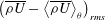 $\left(\overline{\unicode[STIX]{x1D70C}U}-\left\langle \overline{\unicode[STIX]{x1D70C}U}\right\rangle _{\unicode[STIX]{x1D703}}\right)_{\mathit{rms}}$
at each
$\left(\overline{\unicode[STIX]{x1D70C}U}-\left\langle \overline{\unicode[STIX]{x1D70C}U}\right\rangle _{\unicode[STIX]{x1D703}}\right)_{\mathit{rms}}$
at each
 $r$
. Figure 5 depicts contours of the mean flow at each
$r$
. Figure 5 depicts contours of the mean flow at each
 $Re_{z}$
(a,c,e,g,i) with their corresponding mode shapes (b,d,f,h,j).
$Re_{z}$
(a,c,e,g,i) with their corresponding mode shapes (b,d,f,h,j).
Immediately obvious from the figure is that even at
 $Re_{z}=3.5\times 10^{6}$
, the most upstream location, the stationary wave has grown to 20.7 % amplitude. While it does not yet exhibit the characteristic rollover of crossflow vortices, it does appear that this behaviour is already imminent. The dominant circumferential wavenumber falls into the range
$Re_{z}=3.5\times 10^{6}$
, the most upstream location, the stationary wave has grown to 20.7 % amplitude. While it does not yet exhibit the characteristic rollover of crossflow vortices, it does appear that this behaviour is already imminent. The dominant circumferential wavenumber falls into the range
 $50\leqslant k_{c}\leqslant 60$
(
$50\leqslant k_{c}\leqslant 60$
(
 $6^{\circ }\leqslant \unicode[STIX]{x1D706}_{c}\leqslant 7.2^{\circ }$
), in agreement with linear calculations performed by Kuehl et al. (Reference Kuehl, Perez and Reed2012). Here,
$6^{\circ }\leqslant \unicode[STIX]{x1D706}_{c}\leqslant 7.2^{\circ }$
), in agreement with linear calculations performed by Kuehl et al. (Reference Kuehl, Perez and Reed2012). Here,
 $k_{c}$
is the wavenumber per circumference,
$k_{c}$
is the wavenumber per circumference,
 $\unicode[STIX]{x1D706}_{c}$
is the circumferential wavelength, and
$\unicode[STIX]{x1D706}_{c}$
is the circumferential wavelength, and
 $k_{c}=360^{\circ }/\unicode[STIX]{x1D706}_{c}$
.
$k_{c}=360^{\circ }/\unicode[STIX]{x1D706}_{c}$
.
One step downstream, at
 $Re_{z}=3.6\times 10^{6}$
, the degree of development of the stationary vortex structure has visually regressed toward a more sinusoidal state. However, the mode shape indicates that the wave is still growing, with a maximum amplitude of 22.1 %. Additionally, the mode shape itself has become more irregular, showing evidence of the development of a secondary maximum beneath the existing maximum. Indeed, at
$Re_{z}=3.6\times 10^{6}$
, the degree of development of the stationary vortex structure has visually regressed toward a more sinusoidal state. However, the mode shape indicates that the wave is still growing, with a maximum amplitude of 22.1 %. Additionally, the mode shape itself has become more irregular, showing evidence of the development of a secondary maximum beneath the existing maximum. Indeed, at
 $Re_{z}=3.7\times 10^{6}$
, the vortices now exhibit the classical rollover structure and a very clear secondary maximum has developed in the stationary mode, which now reaches a maximum amplitude of 22.8 %.
$Re_{z}=3.7\times 10^{6}$
, the vortices now exhibit the classical rollover structure and a very clear secondary maximum has developed in the stationary mode, which now reaches a maximum amplitude of 22.8 %.
The remaining two measurement locations exhibit a gradual degradation of the stationary vortex structure. The troughs between each upwelling have begun to fill in with lower-momentum fluid and the magnitude of
 $\unicode[STIX]{x1D735}(\overline{\unicode[STIX]{x1D70C}u})$
has started to decrease, as indicated by the spacing between the 10 % contour lines. The mode shapes show a corresponding decrease in amplitude and the two maxima have become less distinct in each case. The amplitudes at
$\unicode[STIX]{x1D735}(\overline{\unicode[STIX]{x1D70C}u})$
has started to decrease, as indicated by the spacing between the 10 % contour lines. The mode shapes show a corresponding decrease in amplitude and the two maxima have become less distinct in each case. The amplitudes at
 $Re_{z}=3.8\times 10^{6}$
and
$Re_{z}=3.8\times 10^{6}$
and
 $3.9\times 10^{6}$
are 18.6 % and 17.6 % respectively.
$3.9\times 10^{6}$
are 18.6 % and 17.6 % respectively.
It is therefore evident that by the middle measurement location, the stationary crossflow wave has reached a state of nonlinear saturation and subsequently begins to attenuate. Additionally, the appearance of the secondary maximum in the mode amplitude tracks very closely with the development of saturation. Both of these phenomena (nonlinear saturation and a secondary maximum in the mode shape) have been observed in incompressible flows, including experiments performed at speeds as low as
 $M\approx 0.1$
(Saric et al.
Reference Saric, Reed and White2003; White & Saric Reference White and Saric2005). Notably different in the Mach 6 case, however, is that the secondary peak in the mode shape occurs below the primary peak.
$M\approx 0.1$
(Saric et al.
Reference Saric, Reed and White2003; White & Saric Reference White and Saric2005). Notably different in the Mach 6 case, however, is that the secondary peak in the mode shape occurs below the primary peak.
3.2 Fluctuations

Figure 6. Colour contours of r.m.s. fluctuations with line contours of 10 % mean flow overlaid. Colour contours are of
 $(\unicode[STIX]{x1D70C}u)_{\mathit{rms}}$
. Starting from the top, the locations are:
$(\unicode[STIX]{x1D70C}u)_{\mathit{rms}}$
. Starting from the top, the locations are:
 $Re_{z}=3.5\times 10^{6}$
,
$Re_{z}=3.5\times 10^{6}$
,
 $3.6\times 10^{6}$
,
$3.6\times 10^{6}$
,
 $3.7\times 10^{6}$
,
$3.7\times 10^{6}$
,
 $3.8\times 10^{6}$
and
$3.8\times 10^{6}$
and
 $3.9\times 10^{6}$
.
$3.9\times 10^{6}$
.
The fluctuating component of
 $\unicode[STIX]{x1D70C}u$
was also analysed by band-passing the hot-wire signal at 300 Hz and 180 kHz in order to remove content below the cutoff of the pre-amplifier and above the frequency response of the hot-wire probe respectively. Figure 6 depicts contours of the r.m.s. of the fluctuations in time at each measurement location. It is evident that, at each location, the regions of maximum fluctuation levels coincide with regions of high
$\unicode[STIX]{x1D70C}u$
was also analysed by band-passing the hot-wire signal at 300 Hz and 180 kHz in order to remove content below the cutoff of the pre-amplifier and above the frequency response of the hot-wire probe respectively. Figure 6 depicts contours of the r.m.s. of the fluctuations in time at each measurement location. It is evident that, at each location, the regions of maximum fluctuation levels coincide with regions of high
 $|\unicode[STIX]{x1D735}(\unicode[STIX]{x1D70C}u)|$
. The r.m.s. fluctuation level is abnormally high in the most upstream location at 11.6 %, before settling down at the last four locations where it measures 7.2 %, 7.8 %, 8.1 % and 7.8 % respectively. The reason for the large fluctuations at
$|\unicode[STIX]{x1D735}(\unicode[STIX]{x1D70C}u)|$
. The r.m.s. fluctuation level is abnormally high in the most upstream location at 11.6 %, before settling down at the last four locations where it measures 7.2 %, 7.8 %, 8.1 % and 7.8 % respectively. The reason for the large fluctuations at
 $Re_{z}=3.5\times 10^{6}$
before settling to a lower, nearly steady level is unclear at present.
$Re_{z}=3.5\times 10^{6}$
before settling to a lower, nearly steady level is unclear at present.
It is clear that the shape of the fluctuating bands in figure 6 are evolving in space. It is therefore useful to investigate the spectral composition of the fluctuations and look for frequency bands that exhibit a high degree of spatial coherence. To this end, power spectra of each point were calculated using Welch’s method (Welch Reference Welch1967) with a Hanning window of size 1024 and a 50 % window overlap. The spectra were then placed in a three-dimensional array,
 ${\mathcal{P}}_{ijk}$
, where the
${\mathcal{P}}_{ijk}$
, where the
 $i$
dimension corresponds to
$i$
dimension corresponds to
 $r$
, the
$r$
, the
 $j$
dimension to
$j$
dimension to
 $\unicode[STIX]{x1D703}$
and the
$\unicode[STIX]{x1D703}$
and the
 $k$
dimension to
$k$
dimension to
 $f$
from the Fourier analysis. In this way, each slice of
$f$
from the Fourier analysis. In this way, each slice of
 ${\mathcal{P}}$
at constant
${\mathcal{P}}$
at constant
 $k$
represents a contour in the
$k$
represents a contour in the
 $(r,\unicode[STIX]{x1D703})$
plane of the frequency content at frequency
$(r,\unicode[STIX]{x1D703})$
plane of the frequency content at frequency
 $f_{k}$
. From this analysis, two frequency bands were identified with their energy concentrated in relatively small and specific regions in space:
$f_{k}$
. From this analysis, two frequency bands were identified with their energy concentrated in relatively small and specific regions in space:
 $15~\text{kHz}\leqslant f\leqslant 60~\text{kHz}$
, denoted
$15~\text{kHz}\leqslant f\leqslant 60~\text{kHz}$
, denoted
 $[15,60]$
, and
$[15,60]$
, and
 $80~\text{kHz}\leqslant f\leqslant 130~\text{kHz}$
, denoted
$80~\text{kHz}\leqslant f\leqslant 130~\text{kHz}$
, denoted
 $[80,130]$
. Fluctuations outside of these bands tended to be nearly evenly distributed throughout the measurement region.
$[80,130]$
. Fluctuations outside of these bands tended to be nearly evenly distributed throughout the measurement region.

Figure 7. Contours of r.m.s. fluctuations in the
 $[15,60]$
band. Contour values are of the r.m.s. of the filtered signal normalized by the maximum filtered r.m.s. measured across all measurement stations. Starting from the top, the locations are:
$[15,60]$
band. Contour values are of the r.m.s. of the filtered signal normalized by the maximum filtered r.m.s. measured across all measurement stations. Starting from the top, the locations are:
 $Re_{z}=3.5\times 10^{6}$
,
$Re_{z}=3.5\times 10^{6}$
,
 $3.6\times 10^{6}$
,
$3.6\times 10^{6}$
,
 $3.7\times 10^{6}$
,
$3.7\times 10^{6}$
,
 $3.8\times 10^{6}$
and
$3.8\times 10^{6}$
and
 $3.9\times 10^{6}$
.
$3.9\times 10^{6}$
.
The
 $\unicode[STIX]{x1D70C}u$
signal at each point was run through an 8-pole Butterworth digital band-pass filter for each of the bands of interest. Figure 7 depicts contours of the r.m.s. fluctuations in the
$\unicode[STIX]{x1D70C}u$
signal at each point was run through an 8-pole Butterworth digital band-pass filter for each of the bands of interest. Figure 7 depicts contours of the r.m.s. fluctuations in the
 $[15,60]$
band. Energy in this band is located in the high-gradient areas between each upwelling and grows more concentrated as the flow develops.
$[15,60]$
band. Energy in this band is located in the high-gradient areas between each upwelling and grows more concentrated as the flow develops.
This frequency band approximately coincides with one observed by Muñoz et al. (Reference Muñoz, Heitmann and Radespiel2014) on nearly identical geometry using surface pressure measurements. In their study, Muñoz et al. attributed the energy in this band to the presence of first-mode waves growing concurrently with the stationary crossflow wave. However, computations by Kuehl et al. (Reference Kuehl, Perez and Reed2012) suggest that the most unstable travelling crossflow waves at the present measurement locations fall into this frequency band for
 $k_{c}=42$
. A set of follow-up calculations performed by Oliviero et al. (Reference Oliviero, Kocian, Moyes and Reed2015) utilizing NPSE at the
$k_{c}=42$
. A set of follow-up calculations performed by Oliviero et al. (Reference Oliviero, Kocian, Moyes and Reed2015) utilizing NPSE at the
 $Re_{z}=3.7\times 10^{6}$
location on the present geometry show a broad region of highly amplified travelling crossflow in the same frequency and wavenumber bands observed in the present experiments (figure 8). It is therefore apparent that travelling crossflow waves are the more likely source of the energy in the
$Re_{z}=3.7\times 10^{6}$
location on the present geometry show a broad region of highly amplified travelling crossflow in the same frequency and wavenumber bands observed in the present experiments (figure 8). It is therefore apparent that travelling crossflow waves are the more likely source of the energy in the
 $[15,60]$
band.
$[15,60]$
band.

Figure 8.
 $N$
-factor contour for travelling waves at
$N$
-factor contour for travelling waves at
 $Re_{z}=3.7\times 10^{6}$
calculated using NPSE.
$Re_{z}=3.7\times 10^{6}$
calculated using NPSE.
These travelling waves also share some of their behaviour with the travelling crossflow waves observed in low-speed flows (White & Saric Reference White and Saric2005). In those experiments, travelling crossflow waves were observed to develop in the regions between low-momentum upwellings and were then drawn into the centre of the vortices. The
 $[15,60]$
band does arise and grow between the upwellings, and there is some evidence that it begins to be drawn under the vortices at higher values of
$[15,60]$
band does arise and grow between the upwellings, and there is some evidence that it begins to be drawn under the vortices at higher values of
 $Re_{z}$
, however it does not exhibit this behaviour to the same degree as the low-speed case, where the travelling wave energy is drawn almost entirely into the upwellings.
$Re_{z}$
, however it does not exhibit this behaviour to the same degree as the low-speed case, where the travelling wave energy is drawn almost entirely into the upwellings.
These data do not necessarily paint a complete picture of the behaviour of the travelling wave. Owing to the sensitivity of the CTA tuning to transonic effects (Kovasznay Reference Kovasznay1950), it is possible that the flow velocity in the upwellings is low enough that these effects become important. This would detune the CTA and dramatically lower its frequency response. In this case, the regions dominated by travelling waves may extend further under the upwellings and simply may not be resolved in the low-velocity region. It is also possible that this behaviour occurs, but only downstream of the measurement region. Further study is therefore required to investigate this behaviour further.

Figure 9. Contours of r.m.s. fluctuations in the
 $[80,130]$
band. Contour values are of the r.m.s. of the filtered signal normalized by the maximum filtered r.m.s. measured across all measurement stations. Starting from the top, the locations are:
$[80,130]$
band. Contour values are of the r.m.s. of the filtered signal normalized by the maximum filtered r.m.s. measured across all measurement stations. Starting from the top, the locations are:
 $Re_{z}=3.5\times 10^{6}$
,
$Re_{z}=3.5\times 10^{6}$
,
 $3.6\times 10^{6}$
,
$3.6\times 10^{6}$
,
 $3.7\times 10^{6}$
,
$3.7\times 10^{6}$
,
 $3.8\times 10^{6}$
and
$3.8\times 10^{6}$
and
 $3.9\times 10^{6}$
.
$3.9\times 10^{6}$
.
The second frequency band of interest is
 $[80,130]$
and is depicted in figure 9. The energy in this band is concentrated almost exclusively along the leeward edges of each upwelling. Based on studies of low-speed crossflow (White & Saric Reference White and Saric2005; Bonfigli & Kloker Reference Bonfigli and Kloker2007) and the expected similarity in the physical mechanisms driving crossflow instability in both Mach regimes, this is the region in which secondary instability is expected to develop. The location of this energy does not change noticeably as
$[80,130]$
and is depicted in figure 9. The energy in this band is concentrated almost exclusively along the leeward edges of each upwelling. Based on studies of low-speed crossflow (White & Saric Reference White and Saric2005; Bonfigli & Kloker Reference Bonfigli and Kloker2007) and the expected similarity in the physical mechanisms driving crossflow instability in both Mach regimes, this is the region in which secondary instability is expected to develop. The location of this energy does not change noticeably as
 $Re_{z}$
increases.
$Re_{z}$
increases.
Figure 10 depicts contours of the normalized
 $r$
(a) and
$r$
(a) and
 $\unicode[STIX]{x1D703}$
(b) components of
$\unicode[STIX]{x1D703}$
(b) components of
 $\unicode[STIX]{x1D735}(\unicode[STIX]{x1D70C}u)$
at
$\unicode[STIX]{x1D735}(\unicode[STIX]{x1D70C}u)$
at
 $Re_{z}=3.86\times 10^{6}$
computed using fourth-order finite differences. The line contour overlay represents the 70 % contour of energy in the
$Re_{z}=3.86\times 10^{6}$
computed using fourth-order finite differences. The line contour overlay represents the 70 % contour of energy in the
 $[80,130]$
band. The location of the high-energy regions have a one-to-one correspondence with the regions of large positive
$[80,130]$
band. The location of the high-energy regions have a one-to-one correspondence with the regions of large positive
 $\unicode[STIX]{x2202}(\overline{\unicode[STIX]{x1D70C}u})/\unicode[STIX]{x2202}\unicode[STIX]{x1D703}$
and appear to have no relationship with
$\unicode[STIX]{x2202}(\overline{\unicode[STIX]{x1D70C}u})/\unicode[STIX]{x2202}\unicode[STIX]{x1D703}$
and appear to have no relationship with
 $\unicode[STIX]{x2202}(\overline{\unicode[STIX]{x1D70C}u})/\unicode[STIX]{x2202}r$
. Further, the high-energy regions extend somewhat over the top of each upwelling beyond the extent of the high
$\unicode[STIX]{x2202}(\overline{\unicode[STIX]{x1D70C}u})/\unicode[STIX]{x2202}r$
. Further, the high-energy regions extend somewhat over the top of each upwelling beyond the extent of the high
 $\unicode[STIX]{x2202}(\overline{\unicode[STIX]{x1D70C}u})/\unicode[STIX]{x2202}\unicode[STIX]{x1D703}$
regions as they are drawn over the top by the stationary vortices.
$\unicode[STIX]{x2202}(\overline{\unicode[STIX]{x1D70C}u})/\unicode[STIX]{x2202}\unicode[STIX]{x1D703}$
regions as they are drawn over the top by the stationary vortices.

Figure 10.
 $r$
gradient (a) and
$r$
gradient (a) and
 $\unicode[STIX]{x1D703}$
gradient (b) of
$\unicode[STIX]{x1D703}$
gradient (b) of
 $\unicode[STIX]{x1D70C}u$
overlaid with 70 % contour lines of energy in the
$\unicode[STIX]{x1D70C}u$
overlaid with 70 % contour lines of energy in the
 $[80,130]$
band at
$[80,130]$
band at
 $Re_{z}=3.86\times 10^{6}$
. Colour contours are of the respective gradient normalized by its maximum amplitude (e.g.
$Re_{z}=3.86\times 10^{6}$
. Colour contours are of the respective gradient normalized by its maximum amplitude (e.g.
 $\unicode[STIX]{x2202}_{\unicode[STIX]{x1D703}}(\overline{\unicode[STIX]{x1D70C}u})/|\unicode[STIX]{x2202}_{\unicode[STIX]{x1D703}}(\overline{\unicode[STIX]{x1D70C}u})|_{\mathit{max}}$
).
$\unicode[STIX]{x2202}_{\unicode[STIX]{x1D703}}(\overline{\unicode[STIX]{x1D70C}u})/|\unicode[STIX]{x2202}_{\unicode[STIX]{x1D703}}(\overline{\unicode[STIX]{x1D70C}u})|_{\mathit{max}}$
).
Additionally, low-speed studies have shown that type-I secondary instabilities occur at frequencies that are proportional to
 $U_{e}/\unicode[STIX]{x1D6FF}$
. White & Saric (Reference White and Saric2005) have shown that the expected frequency should be
$U_{e}/\unicode[STIX]{x1D6FF}$
. White & Saric (Reference White and Saric2005) have shown that the expected frequency should be
 $f\approx U_{e}/(2\unicode[STIX]{x1D6FF})$
. Applying this relationship to
$f\approx U_{e}/(2\unicode[STIX]{x1D6FF})$
. Applying this relationship to
 $U_{e}$
based on the run conditions in M6QT and
$U_{e}$
based on the run conditions in M6QT and
 $\unicode[STIX]{x1D6FF}$
based on the above contours, the predicted frequency of a type-I secondary instability is
$\unicode[STIX]{x1D6FF}$
based on the above contours, the predicted frequency of a type-I secondary instability is
 $f\approx 120~\text{kHz}$
, which falls into the
$f\approx 120~\text{kHz}$
, which falls into the
 $[80,130]$
. Together with the location of this signal and the numerical results obtained by Moyes et al. (Reference Moyes, Paredes, Kocian and Reed2016), the frequency scaling provides strong evidence that the
$[80,130]$
. Together with the location of this signal and the numerical results obtained by Moyes et al. (Reference Moyes, Paredes, Kocian and Reed2016), the frequency scaling provides strong evidence that the
 $[80,130]$
band represents the signature of an incipient type-I secondary instability. Type-II secondary instability was never observed, as the expected frequency is beyond the useful frequency response of the CTA system.
$[80,130]$
band represents the signature of an incipient type-I secondary instability. Type-II secondary instability was never observed, as the expected frequency is beyond the useful frequency response of the CTA system.

Figure 11. Growth of each of the three identified modes.
Three distinct modes have been identified (stationary crossflow, travelling crossflow and type-I secondary instability) and it is instructive to track the growth of each mode individually. Figure 11 depicts the growth of the amplitude of each mode normalized by its amplitude at the most upstream measurement location. These mode amplitudes were defined as the amplitude of the mode shapes for the stationary wave, and the r.m.s. of the corresponding band-passed signal for unsteady modes.
It is an established fact in the low-speed literature that stationary crossflow waves rapidly become nonlinear and saturate, consistent with the present observations. On the contrary, unsteady modes such as the travelling wave and type-I secondary instability have generally been observed to grow. However, the present behaviour is not unprecedented in the low-speed literature. In the experiments performed by White & Saric (Reference White and Saric2005), while most cases showed the travelling wave to grow monotonically, each case exhibited a temporary decrease in growth rate concurrent with the inception of secondary instability, and the low-forcing case in particular exhibited a brief attenuation of the travelling wave (see figure 18, White & Saric Reference White and Saric2005). The same low-forcing case also showed a region of nearly constant amplitude of the type-I secondary instability prior its rapid growth leading to breakdown. It is therefore possible that the region captured in the present study is analogous to this small region just before the explosive growth of the secondary instability in White & Saric (Reference White and Saric2005).
However, the type-I secondary instability in White & Saric (Reference White and Saric2005) exists in a region of length
 $\unicode[STIX]{x0394}Re_{x}\approx 4.8\times 10^{4}$
before its rapid growth leading to breakdown. In the present hypersonic case, the type-I secondary instability has been in existence for at least
$\unicode[STIX]{x0394}Re_{x}\approx 4.8\times 10^{4}$
before its rapid growth leading to breakdown. In the present hypersonic case, the type-I secondary instability has been in existence for at least
 $\unicode[STIX]{x0394}Re_{z}=4\times 10^{5}$
, an order of magnitude longer. Given that the IR thermography does not show evidence of breakdown (figure 4), it is likely that the explosive growth leading to breakdown does not occur on the model at all. The base of the model is at
$\unicode[STIX]{x0394}Re_{z}=4\times 10^{5}$
, an order of magnitude longer. Given that the IR thermography does not show evidence of breakdown (figure 4), it is likely that the explosive growth leading to breakdown does not occur on the model at all. The base of the model is at
 $Re_{z}\approx 4.3\times 10^{6}$
, extending the range of slow or no growth to
$Re_{z}\approx 4.3\times 10^{6}$
, extending the range of slow or no growth to
 $\unicode[STIX]{x0394}Re_{z}\approx 8\times 10^{5}$
.
$\unicode[STIX]{x0394}Re_{z}\approx 8\times 10^{5}$
.
This implies that if, like the low-speed case, the type-I secondary instability is ultimately responsible for breakdown, this process occurs nearly an order of magnitude slower (in terms of Reynolds number) in the hypersonic boundary layer. Alternatively, this may be evidence that, while the early time behaviour of hypersonic crossflow appears very similar to the low-speed case, the breakdown mechanisms may differ. As transition to turbulence never occurs on the model, further experimentation is required to address which of these hypotheses are correct.
3.3 A note on the effect free-stream fluctuations at downstream locations
It is evident from figure 6 that there is a noticeable increase in the fluctuation levels beginning at the middle measurement location,
 $Re_{z}=3.7\times 10^{6}$
. Per the discussion presented in § 2.2, the ‘noisy’ region of the free stream is expected to intersect with the model further downstream than depicted in figure 3 along the leeward side of the cone. It is thus apparent that this occurs at approximately this middle measurement location depicted in these results.
$Re_{z}=3.7\times 10^{6}$
. Per the discussion presented in § 2.2, the ‘noisy’ region of the free stream is expected to intersect with the model further downstream than depicted in figure 3 along the leeward side of the cone. It is thus apparent that this occurs at approximately this middle measurement location depicted in these results.
According to Hofferth & Saric (Reference Hofferth and Saric2012), the free-stream noise is contained primarily in frequency bands in the range
 $f<100~\text{kHz}$
, largely coincident with the travelling wave observed in the present experiment. It is therefore likely that if the free-stream noise has a meaningful effect on the stability of the boundary layer this far downstream, that this would be reflected in the behaviour of the travelling wave, either through simple superposition or through nonlinear interaction.
$f<100~\text{kHz}$
, largely coincident with the travelling wave observed in the present experiment. It is therefore likely that if the free-stream noise has a meaningful effect on the stability of the boundary layer this far downstream, that this would be reflected in the behaviour of the travelling wave, either through simple superposition or through nonlinear interaction.
A bispectral analysis (Hinich & Clay Reference Hinich and Clay1968) was performed at each measurement location using the normalization proposed by Hinich & Wolinsky (Reference Hinich and Wolinsky2005). This analysis produced no evidence of quadratic phase-coupled interactions among the frequencies in this band associated with both the travelling wave and the free-stream fluctuations. In light of this, it is likely that any effect these fluctuations have on the travelling waves would be observed as a simple superposition of the two phenomena. While there is indeed a slight increase in the measured travelling wave amplitude at
 $Re_{z}=3.8\times 10^{6}$
, it is impossible to ascertain whether this is due to the effect of free-stream noise or a feature of the travelling wave evolution. It is, at any rate, a small effect.
$Re_{z}=3.8\times 10^{6}$
, it is impossible to ascertain whether this is due to the effect of free-stream noise or a feature of the travelling wave evolution. It is, at any rate, a small effect.
Additionally, the bispectral analysis did not indicate any interaction between the free-stream noise band and either the stationary mode or the secondary instability. Since the free-stream noise band does not coincide with these two modes, there is no other known mechanism by which the free-stream noise can contaminate the measurements of these modes in the absence of nonlinear interactions.
4 Conclusions
This experiment represents the first detailed data taken throughout the boundary layer in a hypersonic, crossflow-dominated flow. Stationary crossflow vortices were observed to dramatically modify the mean flow. Evidence of coexisting travelling crossflow waves was also observed. A high-frequency secondary instability was observed to grow along the leeward edge of the upwellings in the modified mean flow. Transition to turbulence is not observed in the measurement region and IR thermography suggests it never occurs on the model.
The growth of crossflow instability in a Mach 6 boundary layer is remarkably consistent with that at low speeds. The stationary mode is dominant and causes substantial modification to the mean flow before reaching saturation and beginning to attenuate. Its mode shape features a secondary peak that develops as the stationary wave reaches saturation, though this peak appears below the primary peak, in contrast to the low-speed case. Travelling crossflow waves coexist with the stationary wave and occur in the troughs between the low-momentum upwellings. The energy associated with travelling waves is not observed to be drawn into the upwellings, as is the case at low speeds. However further experiments are necessary to determine whether this behaviour is physical or simply due to the limitations of the present experiments.
The observed secondary instability is of the type-I variety. It arises in regions of large positive
 $\unicode[STIX]{x2202}(\unicode[STIX]{x1D70C}u)/\unicode[STIX]{x2202}\unicode[STIX]{x1D703}$
along the leeward edge of the upwellings and extends diagonally upward and windward, indicating that the secondary modes are convected up and over the upwellings by the stationary vortices. This behaviour is consistent with low-speed, type-I secondary modes. Contrary to the low-speed observations, however, the type-I secondary instability does not exhibit explosive growth shortly after its inception. Instead, the type-I mode saturates for the remainder of the measurement region. While this saturation is not unprecedented (White & Saric Reference White and Saric2005), the lack of evidence of transition in the IR images give strong support to the idea that no rapid growth and breakdown of the existing type-I mode occurs at any point on the model, even at the base, which represents a 10 % increase in
$\unicode[STIX]{x2202}(\unicode[STIX]{x1D70C}u)/\unicode[STIX]{x2202}\unicode[STIX]{x1D703}$
along the leeward edge of the upwellings and extends diagonally upward and windward, indicating that the secondary modes are convected up and over the upwellings by the stationary vortices. This behaviour is consistent with low-speed, type-I secondary modes. Contrary to the low-speed observations, however, the type-I secondary instability does not exhibit explosive growth shortly after its inception. Instead, the type-I mode saturates for the remainder of the measurement region. While this saturation is not unprecedented (White & Saric Reference White and Saric2005), the lack of evidence of transition in the IR images give strong support to the idea that no rapid growth and breakdown of the existing type-I mode occurs at any point on the model, even at the base, which represents a 10 % increase in
 $Re_{z}$
from the most downstream measurement location.
$Re_{z}$
from the most downstream measurement location.
No type-II secondary instability was observed due to the expected high frequency of such a mode lying outside of the useful range of the CTA system. As a result, it is not possible to address the existence and behaviour of these modes and their relative importance as compared to type-I modes with this data set. Further experiments with modified CTA probes are required to achieve the necessary frequency response to address this issue.
The observed behaviour of the type-I mode may represent an entirely new breakdown mechanism for hypersonic crossflow, or may simply indicate a breakdown process is slower to develop than at low speeds such that the secondary instabilities persist for a sizeable downstream distance before their rapid growth. Answering this question definitively will require additional experimentation. M6QT does not support the use of models larger than the used here. It is therefore unlikely that a complete laminar–turbulent transition of naturally occurring, stationary crossflow waves can be achieved in M6QT. The most likely approach to achieving breakdown in M6QT is therefore through controlled forcing of the most unstable stationary wave. Other existing quiet tunnels can support slightly larger models, but it is unclear whether the additional size is enough to produce a natural transition. Furthermore, these facilities typically do not make off-body measurements, limiting the detail they provide about the structure of the boundary layer.
Acknowledgements
The authors would like to acknowledge the computational contributions of T. Kocian and H. Reed. Funding was provided by NASA and AFOSR through the National Center for Hypersonic Laminar-Turbulent Transition Research (AFOSR Grant FA9550-09-1-0341) and by the Texas A&M Foundation through the George Eppright ‘26 Chair in Engineering.


