


1 Introduction
When a vertical wall is heated above the temperature of the ambient fluid, a boundary layer of hot fluid adjacent to it grows in thickness until it becomes unstable and evolves into a plume-like motion (see e.g. Schlichting & Gersten Reference Schlichting and Gersten2000). When this situation is met in a room, container or reservoir, entrainment and mixing with ambient fluid in the closed cavity establishes a stable density stratification (see Baines & Turner Reference Baines and Turner1969). This stratification limits vertical circulation and thus plays an important role in heat transfer as well as for the dispersion of tracers. The evolution is therefore of interest for energy saving applications, the quality of water in reservoirs and air circulation in buildings (Linden Reference Linden1999).
Here, we consider a heated wall that generates a turbulent boundary layer, hereinafter called the wall plume. This wall plume differs from the classic plume as generated by a point source; since heat is forced over the entire depth, the wall imposes zero velocity and the wall blocks the typical meandering plume motion. The entrainment model of Morton, Taylor & Turner (Reference Morton, Taylor and Turner1956) (MTT) has proven very successful for the modelling of plumes and ambient stratification generated by point sources (see Linden Reference Linden1999; Kaye Reference Kaye2008; Woods Reference Woods2010; Hunt & van den Bremer Reference Hunt and van den Bremer2011; Steven & Gregory Reference Steven and Gregory2011, and references therein) or distributed sources along a vertical wall such as those modelled with a constant flux of saline water by Cooper & Hunt (Reference Cooper and Hunt2010). Cooper & Hunt (Reference Cooper and Hunt2010) investigated a wall plume at a vertical boundary generated by injecting a saline solution through a porous sidewall of a square tank, thus providing a constant flux of buoyancy over the entire depth. The evolution of the stratification and the motion of the density front between the heated fluid and the homogeneous ambient in the box showed an overall good agreement of the experimental data with the entrainment model of Morton et al. (Reference Morton, Taylor and Turner1956) that was adapted to a vertically distributed source along the wall.
For an isothermal wall, the heat flux varies with height, since the rising fluid will be subject to a gradually smaller temperature difference with the sidewall. For the laminar case, Worster & Leitch (Reference Worster and Leitch1985) showed that there is no density front as was observed by Baines & Turner (Reference Baines and Turner1969) for a turbulent plume between the homogeneous environment and stratified fluid. Since the laminar boundary layer remains unmixed, it enhances a different stratification than a turbulent wall plume that engulfs and mixes ambient fluid of lower temperatures.
In the present study, we consider a heated wall that gives rise to a wall plume that is laminar near the base and turbulent above a certain height. A hybrid entrainment model, based on the model by Worster & Leitch (Reference Worster and Leitch1985) for the laminar part and Cooper & Hunt (Reference Cooper and Hunt2010) for the turbulent part, is presented, where we consider a constant temperature wall instead of a constant buoyancy flux. With this modelling, we implicitly also respond to questions about the differences in Prandtl number, which is 5.5 for heat flux compared to a Schmidt number of 700 for salt flux experiments. Note that this modelling is one-dimensional as per the MTT model. Although two-dimensional models for wall laminar–turbulent wall plumes are available (see Wells & Worster Reference Wells and Worster2008), we will continue the simpler one-dimensional approach.
The MTT model assumes there is a constant entrainment coefficient in the buoyant plume that is proportional to the mean local vertical velocity and that the buoyant plume fluid is ejected into the non-turbulent ambient (see e.g. Wells, Griffiths & Turner (Reference Wells, Griffiths and Turner1999) for an overview of the MTT model). The laminar model of Worster & Leitch (Reference Worster and Leitch1985) is based on similarity solutions for a heated boundary layer. The transport of a plume generally causes a stratified top layer that increases in depth with time so that the ambient is partially stratified and partially homogeneous. Since the entrainment coefficient in shear layers is higher in a homogeneous fluid than in a stratified fluid (see Fernando Reference Fernando1991), one may expect that, for a plume with constant buoyancy and velocity, the increase of the stratified layer-depth also causes the entrainment coefficient to decrease with time. Usually, a constant entrainment value that does not take into account this variation is considered (see Cooper & Hunt Reference Cooper and Hunt2010). This provides an additional aspect in the modelling. Therefore, measurement results for the plume and the ambient stratification are confronted with the MTT and hybrid plume model, both for a constant and subsequently variable entrainment coefficient.
Although turbulent wall plumes in closed cavities have been investigated numerically, most experimental studies are concerned with local point measurements with probes (see e.g. Tsuji & Nagano Reference Tsuji and Nagano1988). Detailed quantitative information from experiments about the entire temperature and velocity field in the plume and the ambient stratification is not available at present. To test the modelling, a novel experimental measurement technique is used, which allows the simultaneous measurement of temperature and velocity in an entire field and reveals both the details of the plume and the interior stratification. The instantaneous temperature fields are obtained using laser induced fluorescence (LIF) and by taking advantage of the variation in the emission spectrum of certain fluorescent dyes at particular temperatures (Walker Reference Walker1987). This temperature-LIF method (hereinafter called T-LIF) was first tested by Nakajima, Utsunomiya & Ikeda (Reference Nakajima, Utsunomiya and Ikeda1991) for a local measurement and by Sakakibara, Hishida & Maeda (Reference Sakakibara, Hishida and Maeda1993) for a planar field. As far as we know, this method has not been exploited for convective flows, where quantitative information is still limited to point measurements with thermistors or hot wires. For Rhodamine B that is used here, one can expect a fluorescent emission decay of 3.2 %
 $\text{K}^{-1}$
under favourable conditions, which allows for a precision of
$\text{K}^{-1}$
under favourable conditions, which allows for a precision of
 $0.2\,^{\circ }$
C which is close to the precision of a thermistor measurement in a point. Velocity fields are obtained using particle image velocimetry (PIV).
$0.2\,^{\circ }$
C which is close to the precision of a thermistor measurement in a point. Velocity fields are obtained using particle image velocimetry (PIV).
The experimental method is described in detail in § 2. The observations of the plume motion and the interior stratification are discussed in § 3. The entrainment model theory for an isothermal wall is presented with the corresponding numerical models in § 4, and the variation in the entrainment coefficient is discussed. The comparison between experimental results and theoretical models is made in § 5. Results are further discussed in the conclusions in § 6.
2 Experimental measurements
2.1 The experimental setup
Experiments were conducted in a 551 mm-high tank of horizontal section
 $588~\text{mm}\times 300~\text{mm}$
, filled with demineralized water at room temperature (see figure 1). The front and back sides of the tank were made of 20 mm-thick transparent plastic (polymethyl methacrylate, or PMMA), whereas 5 mm-thick aluminium plates at the sidewalls conducted the heat from water in the adjacent compartments to the test section. In the present experiments, one lateral sidewall (volume
$588~\text{mm}\times 300~\text{mm}$
, filled with demineralized water at room temperature (see figure 1). The front and back sides of the tank were made of 20 mm-thick transparent plastic (polymethyl methacrylate, or PMMA), whereas 5 mm-thick aluminium plates at the sidewalls conducted the heat from water in the adjacent compartments to the test section. In the present experiments, one lateral sidewall (volume
 $300~\text{mm}\times 20~\text{mm}\times 551~\text{mm}$
) was filled with hot water which was kept at a constant temperature by means of a thermostatic bath with a maximal power of 2.2 kW and a precision of
$300~\text{mm}\times 20~\text{mm}\times 551~\text{mm}$
) was filled with hot water which was kept at a constant temperature by means of a thermostatic bath with a maximal power of 2.2 kW and a precision of
 $0.1\,^{\circ }$
C. This water was circulating at a rate of
$0.1\,^{\circ }$
C. This water was circulating at a rate of
 $0.43~\text{l}~\text{s}^{-1}$
. For insulation, the other side as well as the bottom were covered with PMMA and PVC, respectively, whereas the top boundary was covered with extruded polystyrene foam (see figure 1
a). Since the aluminium wall was in contact with two liquid baths at different temperatures, its own temperature was situated in between and changed gradually as the tank warmed up. Although this slowed down the total heating time of the test section, and therewith the different phases of the flow evolution, this change was too slow to modify the flow dynamics. Before starting the experiment, it was verified that the fluid in the test section was at rest. At the start of the experiment, hot fluid from the thermostatic bath was injected into the (empty) side compartment. To compensate for the initial transient effects of heating the system, the fluid injected at the start of the experiment was preheated to a few degrees above the desired temperature (
$0.43~\text{l}~\text{s}^{-1}$
. For insulation, the other side as well as the bottom were covered with PMMA and PVC, respectively, whereas the top boundary was covered with extruded polystyrene foam (see figure 1
a). Since the aluminium wall was in contact with two liquid baths at different temperatures, its own temperature was situated in between and changed gradually as the tank warmed up. Although this slowed down the total heating time of the test section, and therewith the different phases of the flow evolution, this change was too slow to modify the flow dynamics. Before starting the experiment, it was verified that the fluid in the test section was at rest. At the start of the experiment, hot fluid from the thermostatic bath was injected into the (empty) side compartment. To compensate for the initial transient effects of heating the system, the fluid injected at the start of the experiment was preheated to a few degrees above the desired temperature (
 $T_{c}$
).
$T_{c}$
).
Experiments were conducted at the initial temperatures of
 $T_{0}=21.4\,^{\circ }$
C in the test section and at
$T_{0}=21.4\,^{\circ }$
C in the test section and at
 $T_{c}=53.6\,^{\circ }$
C in the lateral compartment, the latter being controlled by a probe. This was the maximum temperature difference supported by the experimental device, which was sufficient to get a significantly turbulent plume. The resulting wall temperature was approximately
$T_{c}=53.6\,^{\circ }$
C in the lateral compartment, the latter being controlled by a probe. This was the maximum temperature difference supported by the experimental device, which was sufficient to get a significantly turbulent plume. The resulting wall temperature was approximately
 $39\,^{\circ }$
C (see appendix A for details on the calculation). Therefore, the Rayleigh number and the Prandtl number for our experiments are, respectively,
$39\,^{\circ }$
C (see appendix A for details on the calculation). Therefore, the Rayleigh number and the Prandtl number for our experiments are, respectively,
 $$\begin{eqnarray}Ra_{H}=\frac{g{\it\beta}(T_{c}-T_{0})H^{3}}{{\it\nu}{\it\kappa}}\approx 5.4\times 10^{10}\quad \text{and}\quad Pr=\frac{{\it\nu}}{{\it\kappa}}\approx 5.5,\end{eqnarray}$$
where
 ${\it\beta}$
,
${\it\beta}$
,
 ${\it\nu}$
and
${\it\nu}$
and
 ${\it\kappa}$
are the fluid thermal expansion, kinematic viscosity and thermal diffusivity, respectively (taken at
${\it\kappa}$
are the fluid thermal expansion, kinematic viscosity and thermal diffusivity, respectively (taken at
 $30\,^{\circ }$
C),
$30\,^{\circ }$
C),
 $g$
is the gravitational acceleration and
$g$
is the gravitational acceleration and
 $H$
the height of the cavity. The compartment temperature was kept constant in the present paper, and a dozen tests were conducted for this same temperature difference, with very similar results obtained in all cases.
$H$
the height of the cavity. The compartment temperature was kept constant in the present paper, and a dozen tests were conducted for this same temperature difference, with very similar results obtained in all cases.

Figure 1. Sketch of the experimental setup with (a) the heating system and (b) the PIV/LIF image acquisition system. (a) Front view. (b) General setting.
To monitor the temperature and calibrate the T-LIF images in the test section, the temperature was measured near the rear wall in the middle of the tank with seven to 11 platinum temperature probes (see figure 1
a) with a precision between
 $0.2\,^{\circ }$
C and
$0.2\,^{\circ }$
C and
 $0.5\,^{\circ }$
C. To visualize the particles and the fluorescent dye, the flow was illuminated by a vertical laser sheet shining through a transparent slit at the bottom. A solid continuous laser (Spectra-Physics) of 532 nm operating at 4.5 W was used and generated a beam of 2.3 mm thickness which was transformed into a light sheet by means of an oscillating mirror. Considering the relatively slow velocities in the convection plumes, an oscillating mirror is preferable to a cylindrical lens since it generally provides a more uniform sheet. To ensure identical lighting on every image and minimal exposition of the dye to the laser light, the mirror oscillations were triggered in phase with the image acquisition so that the laser beam passed an integer number of times over the entire view during each exposure time. For temperature measurements with LIF, Rhodamine B was used as fluorescent dye. Details are discussed below (§ 2.2). For PIV measurements, the water was seeded with polyamide tracer particles with a mean diameter of
$0.5\,^{\circ }$
C. To visualize the particles and the fluorescent dye, the flow was illuminated by a vertical laser sheet shining through a transparent slit at the bottom. A solid continuous laser (Spectra-Physics) of 532 nm operating at 4.5 W was used and generated a beam of 2.3 mm thickness which was transformed into a light sheet by means of an oscillating mirror. Considering the relatively slow velocities in the convection plumes, an oscillating mirror is preferable to a cylindrical lens since it generally provides a more uniform sheet. To ensure identical lighting on every image and minimal exposition of the dye to the laser light, the mirror oscillations were triggered in phase with the image acquisition so that the laser beam passed an integer number of times over the entire view during each exposure time. For temperature measurements with LIF, Rhodamine B was used as fluorescent dye. Details are discussed below (§ 2.2). For PIV measurements, the water was seeded with polyamide tracer particles with a mean diameter of
 $30~{\rm\mu}\text{m}$
and a density of
$30~{\rm\mu}\text{m}$
and a density of
 $1016~\text{kg}~\text{m}^{-3}$
.
$1016~\text{kg}~\text{m}^{-3}$
.
The flow was recorded simultaneously by two 12-bit
 $1024\times 1024$
pixel Dalsa CCD cameras at a frame rate of 1 Hz. One camera only recorded the particle positions for PIV measurements by taking bursts of three successive images, and the other camera was equipped with a band filter with wavelengths passing between 565 nm and 585 nm and recorded the fluorescent dye for the T-LIF measurements. To compute the velocity fields for each burst, two pairs of images, representing a short and a long time interval, were processed using the PIV cross-correlation algorithm Uvmat (Matlab toolbox http://servforge.legi.grenoble-inp.fr/projects/soft-uvmat). Thus, we obtained a field containing 17 vectors per square centimetre with an average error estimated at 6 % in the plume region.
$1024\times 1024$
pixel Dalsa CCD cameras at a frame rate of 1 Hz. One camera only recorded the particle positions for PIV measurements by taking bursts of three successive images, and the other camera was equipped with a band filter with wavelengths passing between 565 nm and 585 nm and recorded the fluorescent dye for the T-LIF measurements. To compute the velocity fields for each burst, two pairs of images, representing a short and a long time interval, were processed using the PIV cross-correlation algorithm Uvmat (Matlab toolbox http://servforge.legi.grenoble-inp.fr/projects/soft-uvmat). Thus, we obtained a field containing 17 vectors per square centimetre with an average error estimated at 6 % in the plume region.
All the variables employed in this paper will be described within a Cartesian coordinate system (
 $x,z$
) with
$x,z$
) with
 $z$
being the upward vertical direction (see figure 1
b).
$z$
being the upward vertical direction (see figure 1
b).
2.2 Details of the T-LIF technique
Rhodamine B is a temperature sensitive dye in which the emission sensitivity to temperature changes with wavelength. Dissolved in water, the emission peak is around 575 nm, and the sensitivity to temperature is at its maximum around 570 nm (see Bruchhausen, Guillard & Lemoine Reference Bruchhausen, Guillard and Lemoine2005). An optimal choice for the bandpass filter is found at 565 to 585 nm. To minimize absorption of incident light along the laser path, the Rhodamine B concentration was chosen to be as low as possible. Since the dimensions of the experiment are significantly bigger than the dimensions used in previous T-LIF applications (Coolen et al.
Reference Coolen, Kieft, Rindt and van Steenhoven1999; Bruchhausen et al.
Reference Bruchhausen, Guillard and Lemoine2005; Petracci, Delfos & Westerweel Reference Petracci, Delfos and Westerweel2006), we used a relatively lower concentration here, i.e.
 $3.5\times 10^{-5}~\text{g}~\text{l}^{-1}$
.
$3.5\times 10^{-5}~\text{g}~\text{l}^{-1}$
.
In order to avoid permanent local intensity variations due to light absorption or optical aberrations (see figure 2
a), the images were normalized with two reference fields taken for two homogeneous temperatures
 $T_{lo}$
and
$T_{lo}$
and
 $T_{hi}$
(see Coolen et al.
Reference Coolen, Kieft, Rindt and van Steenhoven1999):
$T_{hi}$
(see Coolen et al.
Reference Coolen, Kieft, Rindt and van Steenhoven1999):
 $$\begin{eqnarray}I_{n}(x,z)=\frac{I(x,z)-I_{hi}(x,z)}{I_{lo}(x,z)-I_{hi}(x,z)}.\end{eqnarray}$$
This equation allows us to find a unique polynomial relation between light intensity and temperature. To obtain this relation, each experiment has been calibrated in advance, using the temperature data from the probes in the tank. An example of this procedure is given in figure 2(b). The final result (see figure 3
a,b) has a precision of approximately
 $\pm 0.2\,^{\circ }$
C (figure 3
c) on a field of
$\pm 0.2\,^{\circ }$
C (figure 3
c) on a field of
 $3200~\text{cm}^{2}$
corresponding to
$3200~\text{cm}^{2}$
corresponding to
 $1024\times 1024$
pixels (see figure 3), which is relatively high compared with previous T-LIF experiments reported in the literature.
$1024\times 1024$
pixels (see figure 3), which is relatively high compared with previous T-LIF experiments reported in the literature.

Figure 2. T-LIF calibration with (a) raw image (axes in centimetres) taken at constant temperature and showing fluorescence intensity variations due to absorption along beam paths and optical reflections. These defaults are corrected by normalization (see text). (b) Normalized intensity
 $I_{n}$
at the position of the vertically distributed temperature probes plotted against their measured temperature. The 11 resulting curves are all fitted by the same second-order polynomial (in this case,
$I_{n}$
at the position of the vertically distributed temperature probes plotted against their measured temperature. The 11 resulting curves are all fitted by the same second-order polynomial (in this case,
 $I_{n}=6.91\times 10^{-4}T^{2}-1.01\times 10^{-1}T+2.86$
).
$I_{n}=6.91\times 10^{-4}T^{2}-1.01\times 10^{-1}T+2.86$
).

Figure 3. Examples of T-LIF results. Grey levels represent temperature in degrees Celsius, axes are in centimetres. (a) Temperature field at the beginning of the experiment (
 $t=50$
s). (b) Temperature field when stratification is established (
$t=50$
s). (b) Temperature field when stratification is established (
 $t=500$
s). Remaining striations that are due to temporal variations in laser light did not affect the results. (c) Stratification profiles taken at different times, averaged over 10 s with probe measurements (
$t=500$
s). Remaining striations that are due to temporal variations in laser light did not affect the results. (c) Stratification profiles taken at different times, averaged over 10 s with probe measurements (
 $+$
) and T-LIF measurements (solid lines).
$+$
) and T-LIF measurements (solid lines).
Note that other methods referred to as ‘two-colour’, based on two dyes (e.g. Coppeta & Rogers Reference Coppeta and Rogers1998) or two spectral bands of the same dye (e.g. Bruchhausen et al. Reference Bruchhausen, Guillard and Lemoine2005), may be used to correct for variations in the illumination. However, the dimensions of our experiment make them very difficult to apply here because of light absorption and re-absorption phenomenon, and, given achieved accuracy of the simpler one-colour method, the expected gain should not be significant.
3 Observations from T-LIF and PIV measurements
3.1 Plume and stratification evolution
At the start of the experiment the heated wall causes a thin hot plume which rises along the boundary and hits the top of the tank (figure 4 a). A vortex motion forms in the top left-hand corner and, while moving to the right along the top boundary, entrains ambient cold fluid at rest (figures 3 a and 4 b). When it hits the right wall, it moves vertically downwards against buoyancy, transferring its energy from inertia into mixing. A gravity-current-like motion results and returns the mixed fluid until it hits the left wall, whereafter the newly formed warm upper layer makes a slumping wave-like motion (figure 4 c–e). This overturning and slumping motion has also been observed for plumes at the centre of a cylindrical tank, with the flow evolution scenario depending on the tank aspect ratio (Kaye & Hunt Reference Kaye and Hunt2007).

Figure 4. Sequence of images showing the onset of the turbulent plume and the establishment of the stratification. Grey levels indicate the temperature and arrows the velocity field. Axes are in centimetres, and temperature is in degrees Celsius. (a–f) Fields at the beginning of the experiment (velocity scale
 $1~\text{cm}:0.1~\text{cm}~\text{s}^{-1}$
). (g–i) Fields at later times (velocity scale
$1~\text{cm}:0.1~\text{cm}~\text{s}^{-1}$
). (g–i) Fields at later times (velocity scale
 $1~\text{cm}:0.05~\text{cm}~\text{s}^{-1}$
).
$1~\text{cm}:0.05~\text{cm}~\text{s}^{-1}$
).
In the next stage of the flow evolution, the wall plume continues to supply hot fluid to this warm upper layer. This layer is now of a slightly lower temperature than that in the plume. In the next stage, instead of a vortex, the plume motion gives rise to a jet-like motion along the top boundary. With the thickening of the upper layer, the local buoyancy decreases and this jet also decreases in intensity as can be inferred from the vectors in figure 4(g–i). The continuous supply of hot fluid above formerly injected fluid causes the descent of the interface. Eventually, after approximately 40 min of heating, the warm upper layer reaches the bottom, and the interior is entirely stratified in temperature (figure 4 g–i).
In the subsequent final stage, the plume entrains fluid from the stratified ambient and gradually decreases the interior temperature gradient. The temperature profiles shown in figures 3(c) and 5 reveal the details of the evolution of the stratification and the gradual heating of the interior. These temperature profiles remain very similar in shape up to approximately 2000 s, i.e. before the warm layer has reached the lower boundary. The temperature profile near the bottom is subsequently distorted because of the laminar character of the plume in this region.

Figure 5. Ambient temperature profiles at different times showing the evolution of stratification.
From the above evolution, we can distinguish three dynamically different zones: (A), (B) and (C) (see figure 5). Zone (A) at the top (
 $z>50$
cm) is characterized by a strong stratification in a thin top layer that is continuously supplied by hot and hardly mixed plume fluid. This warm top layer (A) forms at the very beginning and was also present in the experiments with salt plumes of Cooper & Hunt (Reference Cooper and Hunt2010). Closer inspection of the plume motion below shows that this is due to the thin laminar flow adjacent to the vertical wall. This flow has been modelled in detail by Wells & Worster (Reference Wells and Worster2008). The middle zone (B) (
$z>50$
cm) is characterized by a strong stratification in a thin top layer that is continuously supplied by hot and hardly mixed plume fluid. This warm top layer (A) forms at the very beginning and was also present in the experiments with salt plumes of Cooper & Hunt (Reference Cooper and Hunt2010). Closer inspection of the plume motion below shows that this is due to the thin laminar flow adjacent to the vertical wall. This flow has been modelled in detail by Wells & Worster (Reference Wells and Worster2008). The middle zone (B) (
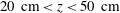 $20~\text{cm}<z<50~\text{cm}$
) is stratified, and exchanges fluid with the wall plume. In the lower layer, zone (C), the plume is thin and laminar. As a consequence, the exchange of fluid and the mixing of the layers is weak. Since the heated layers are pushed downwards by continuity, the temperature gradient in this region increases in time. Eventually, zones (A), (B) and asymptotically also (C) will become homogeneous and obtain the temperature of the heated sidewall.
$20~\text{cm}<z<50~\text{cm}$
) is stratified, and exchanges fluid with the wall plume. In the lower layer, zone (C), the plume is thin and laminar. As a consequence, the exchange of fluid and the mixing of the layers is weak. Since the heated layers are pushed downwards by continuity, the temperature gradient in this region increases in time. Eventually, zones (A), (B) and asymptotically also (C) will become homogeneous and obtain the temperature of the heated sidewall.
To study the turbulent properties of the plume, we consider the Reynolds decomposition
 $u_{i}=\overline{u_{i}}+u_{i}^{\prime }$
, with the bar denoting a time average over 200 s and the prime representing fluctuations. The Reynolds tensor is defined as
$u_{i}=\overline{u_{i}}+u_{i}^{\prime }$
, with the bar denoting a time average over 200 s and the prime representing fluctuations. The Reynolds tensor is defined as
 $\overline{u_{x}^{\prime }u_{z}^{\prime }}$
and is displayed in figure 6(a–c) at three different instants in time (i.e.
$\overline{u_{x}^{\prime }u_{z}^{\prime }}$
and is displayed in figure 6(a–c) at three different instants in time (i.e.
 $t=80$
, 400 and 1600 s), with the highest values at the edge of the plume, indicating turbulent mixing. A clear transition is visible at a height in the range of 22 cm to 25 cm. This transition corresponds to a change in flow regime from laminar to turbulent, as can be evaluated using the local Grashof number defined as
$t=80$
, 400 and 1600 s), with the highest values at the edge of the plume, indicating turbulent mixing. A clear transition is visible at a height in the range of 22 cm to 25 cm. This transition corresponds to a change in flow regime from laminar to turbulent, as can be evaluated using the local Grashof number defined as
 $$\begin{eqnarray}Gr_{z}=\frac{g{\it\beta}{\rm\Delta}Tz^{3}}{{\it\nu}^{2}},\end{eqnarray}$$
where
 ${\rm\Delta}T$
is the temperature difference between the temperature imposed at the wall, and the temperature outside the plume. For
${\rm\Delta}T$
is the temperature difference between the temperature imposed at the wall, and the temperature outside the plume. For
 ${\rm\Delta}T\approx 15\,^{\circ }$
C, the typical transition value of
${\rm\Delta}T\approx 15\,^{\circ }$
C, the typical transition value of
 $10^{9}$
is actually reached at
$10^{9}$
is actually reached at
 $z_{crit}\approx 24$
cm (Bejan & Lage Reference Bejan and Lage1990). Indeed a clear turbulent activity can be noticed in figure 6(a–c) above this height. This transition from laminar to turbulent flow in the boundary layer is noticeable in all measurements.
$z_{crit}\approx 24$
cm (Bejan & Lage Reference Bejan and Lage1990). Indeed a clear turbulent activity can be noticed in figure 6(a–c) above this height. This transition from laminar to turbulent flow in the boundary layer is noticeable in all measurements.
The turbulence and consequently the mixing starts in zone (B). During the flow evolution it also continues to mix when the warm layer has increased in thickness (see figures 6 a–c in relation to 6 d–f). In contrast, close to the wall, the plume is laminar and heated fluid is transported upward without much mixing and causes the high temperature gradient near the top in zone (A). The large temperature gradient perpendicular to the wall is clearly noticeable in figure 6(d–f).

Figure 6. (a–c) Reynolds tensor
 $\overline{u_{x}^{\prime }u_{z}^{\prime }}$
(
$\overline{u_{x}^{\prime }u_{z}^{\prime }}$
(
 $\text{cm}^{2}~\text{s}^{-2}$
) and (d–f) temperature (
$\text{cm}^{2}~\text{s}^{-2}$
) and (d–f) temperature (
 $^{\circ }$
C) in the plume region at
$^{\circ }$
C) in the plume region at
 $t=80$
, 400 and 1600 s after the start of the forcing. Axes are in centimetres.
$t=80$
, 400 and 1600 s after the start of the forcing. Axes are in centimetres.
3.2 Ambient flow characteristics
More detailed information about the flow can be obtained from the local Richardson number, defined as
 $$\begin{eqnarray}Ri=-\frac{g}{{\it\rho}(x,z)}\frac{\partial {\it\rho}(x,z)}{\partial z}/\left(\frac{\partial U(x,z)}{\partial z}\right)^{2},\end{eqnarray}$$
where
 ${\it\rho}(x,z)$
and
${\it\rho}(x,z)$
and
 $U(x,z)$
are the local density and velocity, respectively. In general, the Richardson number reveals gravitational instabilities (
$U(x,z)$
are the local density and velocity, respectively. In general, the Richardson number reveals gravitational instabilities (
 $\partial {\it\rho}(x,z)/\partial z>0$
) and shear or Kelvin–Helmholtz instabilities (
$\partial {\it\rho}(x,z)/\partial z>0$
) and shear or Kelvin–Helmholtz instabilities (
 $0<Ri<1/4$
). Gravitational instabilities are very localized to instantaneous and intermittent flow reversals during the initial flow stage (see figure 4
b). Therefore, here we focus on shear instabilities that are displayed for visualization purposes on a logarithmic scale of the absolute Richardson number in figure 7). The details of the mixing are highlighted by the low (dark) values of the Richardson number. In particular, the mixing due to the continued plume motion along the top boundary is important during the upper layer formation and its growth in time (see figure 7
a–f). After the upper layer formation in the initial flow stage, the mixing occurs principally between the rising plume and the interior, whereas the mixing between the upper and lower layer is negligible (see figure 7
e–g).
$0<Ri<1/4$
). Gravitational instabilities are very localized to instantaneous and intermittent flow reversals during the initial flow stage (see figure 4
b). Therefore, here we focus on shear instabilities that are displayed for visualization purposes on a logarithmic scale of the absolute Richardson number in figure 7). The details of the mixing are highlighted by the low (dark) values of the Richardson number. In particular, the mixing due to the continued plume motion along the top boundary is important during the upper layer formation and its growth in time (see figure 7
a–f). After the upper layer formation in the initial flow stage, the mixing occurs principally between the rising plume and the interior, whereas the mixing between the upper and lower layer is negligible (see figure 7
e–g).

Figure 7. Absolute value of Richardson number
 $Ri=|-(g/{\it\rho})(\partial {\it\rho}/\partial z)/(\partial U/\partial z)^{2}|$
at different times corresponding to figure 4 using a logarithmic scale (
$Ri=|-(g/{\it\rho})(\partial {\it\rho}/\partial z)/(\partial U/\partial z)^{2}|$
at different times corresponding to figure 4 using a logarithmic scale (
 $Ri>1$
in white zones). Black spots in the unstratified zone (C) (
$Ri>1$
in white zones). Black spots in the unstratified zone (C) (
 $(g/{\it\rho})(\partial {\it\rho}/\partial z)\approx 0$
) are due to noise. Axes are in centimetres.
$(g/{\it\rho})(\partial {\it\rho}/\partial z)\approx 0$
) are due to noise. Axes are in centimetres.
The streamlines and stratification in figure 8 show the averaged flow evolution of the circulation during the warm layer deepening. As in the case of a laminar plume (see Worster & Leitch Reference Worster and Leitch1985, figure 7), the hot fluid injection along the top boundary causes the entire stratification to move downwards. The difference with laminar flow is apparent from the turbulent exchange of the warm layer with the plume motion (top-left quarter), and becomes more pronounced with time from the circulation pattern in figure 8(b,c). This exchange and consecutive mixing in the plume is responsible for the presence of the front between the upper and lower layer. This front is indeed absent in the case of a laminar plume. In the lower layer, by continuity, the descending interface forces the fluid in the lower layer into the plume. This effect becomes more pronounced once the lower layer is thinner and the motion remains horizontal (figure 8 c).

Figure 8. Velocity (arrows) and temperature (grey levels) fields averaged over 200 s, with streamline patterns. Axes are in centimetres, temperature is in degrees Celsius. Time averages cover the spans (a)
 $t=100{-}300$
s, (b)
$t=100{-}300$
s, (b)
 $t=700{-}900$
s and (c)
$t=700{-}900$
s and (c)
 $t=2300{-}2500$
s.
$t=2300{-}2500$
s.

Figure 9. Averaged quantities in the plume. (a) Typical vertical velocity and temperature profiles (at
 $z\approx 40$
cm and
$z\approx 40$
cm and
 $t=150$
s). The dotted lines show the top-hat profile used in the model (§ 4). (b) Plume width
$t=150$
s). The dotted lines show the top-hat profile used in the model (§ 4). (b) Plume width
 $b$
as a function of
$b$
as a function of
 $z$
at different times. (c) Plume characteristic velocity
$z$
at different times. (c) Plume characteristic velocity
 $w$
as a function of
$w$
as a function of
 $z$
at the same times.
$z$
at the same times.
3.3 Wall plume details for the modelling
Figure 9(a) shows the velocity and temperature profiles in the plume. To reduce the scatter, the data (recorded with a frequency of 1 Hz) are averaged over a period of 30 s. These velocity and temperature profiles conserve their general shape at all heights. To determine the characteristic quantities of the plume which are used in the model, i.e. the plume width
 $b(z)$
, the characteristic plume velocity
$b(z)$
, the characteristic plume velocity
 $w(z)$
and the characteristic plume temperature
$w(z)$
and the characteristic plume temperature
 $T(z)$
, we have used conservation of volume, momentum and energy (buoyancy) fluxes. They can be written for all
$T(z)$
, we have used conservation of volume, momentum and energy (buoyancy) fluxes. They can be written for all
 $z$
as
$z$
as
 $$\begin{eqnarray}\displaystyle b(z)w(z)=\int _{0}^{\infty }u_{z}(x,z)\,\text{d}x,\quad b(z)w(z)^{2}=\int _{0}^{\infty }u_{z}(x,z)^{2}\,\text{d}x & & \displaystyle\end{eqnarray}$$
and
 $$\begin{eqnarray}\displaystyle b(z)w(z)(T(z)-T_{e}(z))=\int _{0}^{\infty }u_{z}(x,z)(T_{xz}(x,z)-T_{e}(z))\,\text{d}x, & & \displaystyle\end{eqnarray}$$
where
 $u_{z}(x,z)$
and
$u_{z}(x,z)$
and
 $T_{xz}(x,z)$
are the local vertical velocity and temperature, respectively, and
$T_{xz}(x,z)$
are the local vertical velocity and temperature, respectively, and
 $T_{e}(z)$
is the ambient temperature. To simplify notation,
$T_{e}(z)$
is the ambient temperature. To simplify notation,
 $b(z)$
,
$b(z)$
,
 $w(z)$
and
$w(z)$
and
 $T(z)$
will be written as
$T(z)$
will be written as
 $b$
,
$b$
,
 $w$
and
$w$
and
 $T$
, respectively, in the following.
$T$
, respectively, in the following.
The profiles of
 $b$
and
$b$
and
 $w$
(in figures 9
b and 9
c, respectively) clearly show the laminar–turbulent transition in the wall plume at
$w$
(in figures 9
b and 9
c, respectively) clearly show the laminar–turbulent transition in the wall plume at
 $z\approx 24$
cm in accordance with figure 6(a–c). For
$z\approx 24$
cm in accordance with figure 6(a–c). For
 $2~\text{cm}<z\lesssim 24$
cm the plume width remains almost constant while velocity increases linearly, and it expands in the zone for
$2~\text{cm}<z\lesssim 24$
cm the plume width remains almost constant while velocity increases linearly, and it expands in the zone for
 $24~\text{cm}<z<45$
cm (see also figure 6
a–c). The increase in plume width is not balanced by an equivalent gain in volume flux, so that the velocity
$24~\text{cm}<z<45$
cm (see also figure 6
a–c). The increase in plume width is not balanced by an equivalent gain in volume flux, so that the velocity
 $w$
decreases. At the upper boundary the vertical volume flux goes to zero, and the plume is deviated horizontally. Since the vertical velocity also changes to zero, the evaluation of
$w$
decreases. At the upper boundary the vertical volume flux goes to zero, and the plume is deviated horizontally. Since the vertical velocity also changes to zero, the evaluation of
 $b$
becomes meaningless, as is apparent at
$b$
becomes meaningless, as is apparent at
 $z>45$
cm (figure 9
b).
$z>45$
cm (figure 9
b).
3.4 The entrainment coefficient
The entrainment coefficient is the key parameter for the modelling described below and will be determined empirically. It is evaluated with the equation of volume conservation (4.1) introduced in next section:
 $$\begin{eqnarray}{\it\alpha}=\frac{1}{w}\frac{\text{d}(bw)}{\text{d}z}.\end{eqnarray}$$
The experimental values for
 $bw$
and
$bw$
and
 $w$
are accurately obtained from PIV measurements. Using a linear regression between
$w$
are accurately obtained from PIV measurements. Using a linear regression between
 $\text{d}(bw)/\text{d}z$
and
$\text{d}(bw)/\text{d}z$
and
 $w$
, a unique value for
$w$
, a unique value for
 ${\it\alpha}$
is calculated at each time step for the entire wall plume and therefore includes the contributions of both the homogeneous and the stratified zones of the turbulent plume (see appendix B for details). The values are plotted in figure 10(a) against time. It starts around 0.08 when the environment is still homogeneous, a value which is close to that of a buoyant jet (e.g. Ellison & Turner Reference Ellison and Turner1959; Kaminski, Tait & Carazzo Reference Kaminski, Tait and Carazzo2005) or a fountain (e.g. Baines Reference Baines2002). The time-averaged value
${\it\alpha}$
is calculated at each time step for the entire wall plume and therefore includes the contributions of both the homogeneous and the stratified zones of the turbulent plume (see appendix B for details). The values are plotted in figure 10(a) against time. It starts around 0.08 when the environment is still homogeneous, a value which is close to that of a buoyant jet (e.g. Ellison & Turner Reference Ellison and Turner1959; Kaminski, Tait & Carazzo Reference Kaminski, Tait and Carazzo2005) or a fountain (e.g. Baines Reference Baines2002). The time-averaged value
 ${\it\alpha}=0.019$
is in good agreement with the entrainment value obtained by Cooper & Hunt (Reference Cooper and Hunt2010), which was obtained from the position of the density front. Although their value is close to the present one for
${\it\alpha}=0.019$
is in good agreement with the entrainment value obtained by Cooper & Hunt (Reference Cooper and Hunt2010), which was obtained from the position of the density front. Although their value is close to the present one for
 $t>1000$
s, there is a non-negligible decrease of a factor close to 10 during the establishment of the stratification over the depth of the tank.
$t>1000$
s, there is a non-negligible decrease of a factor close to 10 during the establishment of the stratification over the depth of the tank.

Figure 10. (a) Experimental entrainment coefficient
 ${\it\alpha}$
calculated with (3.5) for the entire plume against time, with the average value (dash-dotted line) and exponential fit (dashed line) with
${\it\alpha}$
calculated with (3.5) for the entire plume against time, with the average value (dash-dotted line) and exponential fit (dashed line) with
 $t_{0}$
taken at 30 s for the onset time of the plume. (b) Entrainment coefficient,
$t_{0}$
taken at 30 s for the onset time of the plume. (b) Entrainment coefficient,
 ${\it\alpha}$
, for the turbulent part of the plume (red), the laminar part (green) and total plume (blue) with the respective exponential fits. The data have been averaged over 20 s.
${\it\alpha}$
, for the turbulent part of the plume (red), the laminar part (green) and total plume (blue) with the respective exponential fits. The data have been averaged over 20 s.
The consequent raise in temperature of the interior also decreases the buoyancy flux of the plume. The mean Reynolds stress term therewith decreases in time by approximately a factor of four, but the height of the transition between laminar and turbulent regimes characterized by the Grashof number hardly moves (see figure 6). This indicates that the turbulence activity of the plume decreases in time, but that it remains nevertheless turbulent. As mentioned above, in shear flows the entrainment coefficient in a stratified fluid is relatively small compared with that in a homogeneous fluid (see Fernando Reference Fernando1991). Since variations in time of buoyancy and velocity in the plume remain limited, it is the increase in stratified layer-depth in the ambient which decreases the entrainment coefficient.
Figure 10(b) differentiates the evolution of
 ${\it\alpha}$
in the turbulent (B) and laminar zones (A). (Note that the mechanism of entrainment in the laminar case is essentially different, but the definition (3.5) can still be used in this zone.) The initial rapid decrease of
${\it\alpha}$
in the turbulent (B) and laminar zones (A). (Note that the mechanism of entrainment in the laminar case is essentially different, but the definition (3.5) can still be used in this zone.) The initial rapid decrease of
 ${\it\alpha}$
in the turbulent zone is due to the increasing stratified layer-depth, with the minimal value reached when eventually the interior is entirely stratified (see figure 7
i). In the laminar zone,
${\it\alpha}$
in the turbulent zone is due to the increasing stratified layer-depth, with the minimal value reached when eventually the interior is entirely stratified (see figure 7
i). In the laminar zone,
 ${\it\alpha}$
remains constant at the beginning as the density of the ambient does not change, and then it decreases after approximately 600 s, when the front reaches the laminar part of the plume.
${\it\alpha}$
remains constant at the beginning as the density of the ambient does not change, and then it decreases after approximately 600 s, when the front reaches the laminar part of the plume.
The sampling of the present data are not sufficient to calculate the local entrainment coefficient. However, figure 5 shows that the global temperature gradient in the turbulent zone (B) remains approximately constant (see figure 10
b after 1200 s). The entrainment coefficient within this stratified zone is also found approximately constant. The two constant values for
 ${\it\alpha}$
, for the homogeneous and the stratified regions, allow the decrease of
${\it\alpha}$
, for the homogeneous and the stratified regions, allow the decrease of
 ${\it\alpha}$
observed in the turbulent zone to be accurately reproduced. The details of this calculation are shown in appendix B.
${\it\alpha}$
observed in the turbulent zone to be accurately reproduced. The details of this calculation are shown in appendix B.
4 Theoretical modelling
In order to model the heated boundary, we consider a vertical distributed source of buoyancy and herein closely follow the approach of Cooper & Hunt (Reference Cooper and Hunt2010) based on the plume theory that is originally developed by Morton et al. (Reference Morton, Taylor and Turner1956). The main differences in the present approach are that the temperature rather than heat flux is imposed and that the heated wall is placed in a closed cavity without openings.
4.1 The turbulent conservation equations
We consider an adiabatic prismatic box of height
 $H$
, width
$H$
, width
 $L$
(along
$L$
(along
 $y$
) and horizontal cross-sectional area
$y$
) and horizontal cross-sectional area
 $A$
. At one sidewall, a distributed buoyancy source emits a buoyancy flux per unit area
$A$
. At one sidewall, a distributed buoyancy source emits a buoyancy flux per unit area
 ${\it\phi}$
. The plume is considered to be fully turbulent and, in accordance with Morton et al. (Reference Morton, Taylor and Turner1956) theory, we assume the Boussinesq approximation, and the similarity of the velocity and buoyancy profiles with height. Furthermore, the velocity profile is assumed to be top-hat and the rate of entrainment proportional to the velocity at that height. All water properties except density are assumed to be constant with temperature.
${\it\phi}$
. The plume is considered to be fully turbulent and, in accordance with Morton et al. (Reference Morton, Taylor and Turner1956) theory, we assume the Boussinesq approximation, and the similarity of the velocity and buoyancy profiles with height. Furthermore, the velocity profile is assumed to be top-hat and the rate of entrainment proportional to the velocity at that height. All water properties except density are assumed to be constant with temperature.
The width of the plume, its vertical velocity and relative buoyancy are respectively denoted as
 $b$
,
$b$
,
 $w$
and
$w$
and
 ${\it\Delta}$
;
${\it\Delta}$
;
 ${\it\Delta}$
can be expressed as
${\it\Delta}$
can be expressed as
 ${\it\Delta}=g({\it\rho}_{e}-{\it\rho})/{\it\rho}_{1}=g{\it\beta}(T-T_{e})$
. Subscripts ‘
${\it\Delta}=g({\it\rho}_{e}-{\it\rho})/{\it\rho}_{1}=g{\it\beta}(T-T_{e})$
. Subscripts ‘
 $e$
’ and ‘1’ refer to ambient and reference fluid, respectively, whereas variables with no subscript refer to the plume. The reference variables may conveniently correspond to the characteristics of the fluid at
$e$
’ and ‘1’ refer to ambient and reference fluid, respectively, whereas variables with no subscript refer to the plume. The reference variables may conveniently correspond to the characteristics of the fluid at
 $t=0$
. Let us also introduce the ambient buoyancy
$t=0$
. Let us also introduce the ambient buoyancy
 ${\it\Delta}_{e}=g({\it\rho}_{e}-{\it\rho}_{1})/{\it\rho}_{1}=g{\it\beta}(T_{1}-T_{e})$
. The conservation equations for volume, momentum and buoyancy deficiency in the plume are written as
${\it\Delta}_{e}=g({\it\rho}_{e}-{\it\rho}_{1})/{\it\rho}_{1}=g{\it\beta}(T_{1}-T_{e})$
. The conservation equations for volume, momentum and buoyancy deficiency in the plume are written as
 $$\begin{eqnarray}\frac{\text{d}(bw)}{\text{d}z}={\it\alpha}w,\quad \frac{\text{d}(bw^{2})}{\text{d}z}=b{\it\Delta}-{\it\varepsilon}\quad \text{and}\quad \frac{\text{d}(bw{\it\Delta})}{\text{d}z}=bw\frac{\partial {\it\Delta}_{e}}{\partial z}+{\it\phi},\end{eqnarray}$$
where
 ${\it\varepsilon}$
accounts for dissipation due to wall shear stress that we will neglect in the following.
${\it\varepsilon}$
accounts for dissipation due to wall shear stress that we will neglect in the following.
Unlike in Cooper & Hunt (Reference Cooper and Hunt2010), the buoyancy flux,
 ${\it\phi}$
, is variable due to the heat flux,
${\it\phi}$
, is variable due to the heat flux,
 ${\it\varphi}$
, across the wall. Their relation per unit area across the wall is given by
${\it\varphi}$
, across the wall. Their relation per unit area across the wall is given by
 $$\begin{eqnarray}{\it\phi}=\frac{g{\it\beta}}{{\it\rho}_{1}C_{p}}{\it\varphi},\end{eqnarray}$$
where
 $C_{p}$
is the specific heat capacity of water at constant pressure. The heat flux,
$C_{p}$
is the specific heat capacity of water at constant pressure. The heat flux,
 ${\it\varphi}$
, has to be defined here as a function of the temperature imposed at the wall
${\it\varphi}$
, has to be defined here as a function of the temperature imposed at the wall
 $T_{w}$
and the temperature of the ambient fluid
$T_{w}$
and the temperature of the ambient fluid
 $T_{e}$
. Then we write
$T_{e}$
. Then we write
 $$\begin{eqnarray}{\it\varphi}=h_{w}(T_{w}-T_{e}),\end{eqnarray}$$
where
 $h_{w}$
is the heat transfer coefficient which can be expressed according to Tsuji & Nagano (Reference Tsuji and Nagano1988) as
$h_{w}$
is the heat transfer coefficient which can be expressed according to Tsuji & Nagano (Reference Tsuji and Nagano1988) as
 $$\begin{eqnarray}h_{w}=K_{w}k\left(\frac{g{\it\beta}(T_{w}-T_{e})}{{\it\nu}{\it\kappa}}\right)^{1/3},\end{eqnarray}$$
where the constant
 $K_{w}=0.120$
and
$K_{w}=0.120$
and
 $k$
is the thermal conductivity of the fluid. Since the buoyancy term for the ambient was written as
$k$
is the thermal conductivity of the fluid. Since the buoyancy term for the ambient was written as
 ${\it\Delta}_{e}=g{\it\beta}(T_{1}-T_{e})$
, where
${\it\Delta}_{e}=g{\it\beta}(T_{1}-T_{e})$
, where
 $T_{1}$
is the reference temperature, one can introduce a wall buoyancy,
$T_{1}$
is the reference temperature, one can introduce a wall buoyancy,
 ${\it\Delta}_{w}$
, defined as
${\it\Delta}_{w}$
, defined as
 ${\it\Delta}_{w}=g{\it\beta}(T_{w}-T_{1})$
, so that (4.2) becomes
${\it\Delta}_{w}=g{\it\beta}(T_{w}-T_{1})$
, so that (4.2) becomes
 $$\begin{eqnarray}{\it\phi}={A_{w}}^{1/3}({\it\Delta}_{e}+{\it\Delta}_{w})^{4/3},\end{eqnarray}$$
where
 $A_{w}={K_{w}}^{3}({\it\kappa}^{2}/{\it\nu})$
is the effective diffusion constant quantifying the buoyancy flux from the wall. Re-writing the conservation equations in terms of volume flux
$A_{w}={K_{w}}^{3}({\it\kappa}^{2}/{\it\nu})$
is the effective diffusion constant quantifying the buoyancy flux from the wall. Re-writing the conservation equations in terms of volume flux
 $Q=bw$
, momentum flux
$Q=bw$
, momentum flux
 $M=bw^{2}$
and buoyancy flux
$M=bw^{2}$
and buoyancy flux
 $F=bw{\it\Delta}$
, the equations (4.1) reduce to
$F=bw{\it\Delta}$
, the equations (4.1) reduce to
 $$\begin{eqnarray}\frac{\text{d}Q}{\text{d}z}={\it\alpha}\frac{M}{Q},\quad \frac{\text{d}M}{\text{d}z}=\frac{QF}{M}\quad \text{and}\quad \frac{\text{d}F}{\text{d}z}=Q\frac{\partial {\it\Delta}_{e}}{\partial z}+{A_{w}}^{1/3}({\it\Delta}_{e}+{\it\Delta}_{w})^{4/3}.\end{eqnarray}$$
In ‘filling-box’ models the characteristic time scales of the ambient are assumed to be much larger than those in the plume. The heat equation in the ambient fluid is then written as
 $$\begin{eqnarray}\frac{\partial {\it\Delta}_{e}}{\partial t}=-U\frac{\partial {\it\Delta}_{e}}{\partial z}+{\it\kappa}\frac{\partial ^{2}{\it\Delta}_{e}}{\partial z^{2}},\end{eqnarray}$$
where
 $U$
is the vertical velocity of the ambient. Following Baines & Turner (Reference Baines and Turner1969)’s assumption for which the plume width is negligible compared with the horizontal cross-section of the box (i.e.
$U$
is the vertical velocity of the ambient. Following Baines & Turner (Reference Baines and Turner1969)’s assumption for which the plume width is negligible compared with the horizontal cross-section of the box (i.e.
 $b\ll A/L$
),
$b\ll A/L$
),
 $U$
can be expressed as
$U$
can be expressed as
 $U=-QL/A$
.
$U=-QL/A$
.
We non-dimensionalize equations (4.6) and (4.7) with the scalings
 $$\begin{eqnarray}\left.\begin{array}{@{}c@{}}{\it\zeta}=H^{-1}z,\quad {\it\tau}=LA^{-1}H^{-1}A_{w}t,\quad {\it\delta}_{e}=H^{3}{A_{w}}^{-2}{\it\Delta}_{e},\\ f=H^{3}{A_{w}}^{-3}F,\quad q={A_{w}}^{-4}Q,\quad m=H{A_{w}}^{-2}M\end{array}\right\}\end{eqnarray}$$
and obtain for the conservation equations
 $$\begin{eqnarray}\left.\begin{array}{@{}c@{}}\displaystyle \frac{\text{d}q}{\text{d}{\it\zeta}}={\it\alpha}\frac{m}{q},\\ \displaystyle \frac{\text{d}m}{\text{d}{\it\zeta}}=\frac{qf}{m},\\ \displaystyle \frac{\text{d}f}{\text{d}{\it\zeta}}=q\frac{\partial {\it\delta}_{e}}{\partial {\it\zeta}}+({\it\delta}_{e}+{\it\delta}_{w})^{4/3}.\end{array}\right\}\end{eqnarray}$$
Here the wall buoyancy term,
 ${\it\delta}_{w}$
, is
${\it\delta}_{w}$
, is
 $$\begin{eqnarray}{\it\delta}_{w}={K_{w}}^{-6}Pr^{3}Ra_{H},\end{eqnarray}$$
and the Rayleigh and Prandtl numbers introduced are defined as
 $$\begin{eqnarray}Ra_{H}=\frac{g{\it\beta}(T_{w}-T_{1})H^{3}}{{\it\nu}{\it\kappa}}\quad \text{and}\quad Pr=\frac{{\it\nu}}{{\it\kappa}}.\end{eqnarray}$$
For the heat equation (4.7), we obtain in non-dimensional form
 $$\begin{eqnarray}\frac{\partial {\it\delta}_{e}}{\partial {\it\tau}}=q\frac{\partial {\it\delta}_{e}}{\partial {\it\zeta}}+\frac{Pr}{{K_{w}}^{3}}\frac{A}{HL}\frac{\partial ^{2}{\it\delta}_{e}}{\partial {\it\zeta}^{2}},\end{eqnarray}$$
where
 $HL/A$
is the box aspect ratio. The second term on the right-hand side expressing molecular diffusion in the ambient is neglected in the following.
$HL/A$
is the box aspect ratio. The second term on the right-hand side expressing molecular diffusion in the ambient is neglected in the following.
With equations (4.9) and (4.12), we can now determine the position of the first disturbed zone in the ambient, corresponding to the lower limit of the interface between the upper and lower layer (see Worster & Huppert Reference Worster and Huppert1983). For an initially uniform ambient, i.e.
 $\partial {\it\delta}_{e}/\partial {\it\zeta}=0$
, for the vertical position of the front, denoted
$\partial {\it\delta}_{e}/\partial {\it\zeta}=0$
, for the vertical position of the front, denoted
 ${\it\zeta}_{fr}$
, one obtains
${\it\zeta}_{fr}$
, one obtains
 $$\begin{eqnarray}\frac{\text{d}{\it\zeta}_{fr}}{\text{d}{\it\tau}}=-\frac{3}{4}\left(\frac{4}{5}\right)^{1/3}{\it\alpha}^{2/3}({\it\delta}_{e}^{fr}+{\it\delta}_{w})^{4/9}{\it\zeta}_{fr}^{4/3},\end{eqnarray}$$
where
 ${\it\delta}_{e}^{fr}$
is the initial ambient buoyancy. This can be integrated using the condition
${\it\delta}_{e}^{fr}$
is the initial ambient buoyancy. This can be integrated using the condition
 ${\it\zeta}_{fr}({\it\tau}=0)=1$
to give
${\it\zeta}_{fr}({\it\tau}=0)=1$
to give
 $$\begin{eqnarray}{\it\zeta}_{fr}=\left[1+{\textstyle \frac{1}{4}}\left({\textstyle \frac{4}{5}}\right)^{1/3}{\it\alpha}({\it\delta}_{e}^{fr}+{\it\delta}_{w})^{4/9}{\it\tau}\right]^{-3}.\end{eqnarray}$$
Note that the front position in time depends directly on the entrainment coefficient
 ${\it\alpha}$
.
${\it\alpha}$
.
4.2 Hybrid model including the laminar part
As we have seen in the experimental results, the wall plume is laminar over approximately one-third of its height. This requires a particular treatment, especially for configurations with a lower Grashof number than the present one. Below, the variables with a hat are used for the modelling of the laminar zone. In order to measure its influence, similarity solutions are used for the stream function
 ${\it\psi}$
and the temperature perturbation
${\it\psi}$
and the temperature perturbation
 $T-T_{e}$
, given a stratification profile proportional to some power of
$T-T_{e}$
, given a stratification profile proportional to some power of
 $z$
(see Worster & Leitch Reference Worster and Leitch1985). Defining
$z$
(see Worster & Leitch Reference Worster and Leitch1985). Defining
 ${\it\psi}$
such that
${\it\psi}$
such that
 $u_{x}=-\partial {\it\psi}/\partial z$
and
$u_{x}=-\partial {\it\psi}/\partial z$
and
 $u_{z}=\partial {\it\psi}/\partial x$
, these similarity solutions are written in terms of non-dimensional functions
$u_{z}=\partial {\it\psi}/\partial x$
, these similarity solutions are written in terms of non-dimensional functions
 $\widehat{F}(\hat{{\it\xi}})$
and
$\widehat{F}(\hat{{\it\xi}})$
and
 $\widehat{G}(\hat{{\it\xi}})$
as
$\widehat{G}(\hat{{\it\xi}})$
as
 $$\begin{eqnarray}\displaystyle {\it\psi}={\it\kappa}({\it\lambda}_{T}Ra_{z})^{(1-\hat{m})/4}\widehat{F}(\hat{{\it\xi}}),\quad \text{and}\quad T-T_{e}={\it\lambda}_{T}(T_{w}-T_{1})({\it\lambda}_{T}Ra_{z})^{-\hat{m}}\widehat{G}(\hat{{\it\xi}}). & & \displaystyle\end{eqnarray}$$
The constants
 ${\it\lambda}_{T}$
and
${\it\lambda}_{T}$
and
 $\hat{m}$
characterize the density profile and satisfy the relation
$\hat{m}$
characterize the density profile and satisfy the relation
 $$\begin{eqnarray}\frac{T_{w}-T_{e}}{T_{w}-T_{1}}={\it\lambda}_{T}^{1-\hat{m}}Ra_{z}^{-\hat{m}}.\end{eqnarray}$$
(For the Rayleigh number Worster & Leitch (Reference Worster and Leitch1985) use a characteristic temperature scale denoted
 ${\rm\Delta}T$
, which is obtained from the instant density profile. To keep the Rayleigh number fixed, here
${\rm\Delta}T$
, which is obtained from the instant density profile. To keep the Rayleigh number fixed, here
 ${\rm\Delta}T$
is replaced by
${\rm\Delta}T$
is replaced by
 ${\it\lambda}_{T}(T_{w}-T_{1})$
, where the density variation is represented by the coefficient
${\it\lambda}_{T}(T_{w}-T_{1})$
, where the density variation is represented by the coefficient
 ${\it\lambda}_{T}$
.) The ambient is homogeneous when
${\it\lambda}_{T}$
.) The ambient is homogeneous when
 $\hat{m}=0$
, and stably stratified for
$\hat{m}=0$
, and stably stratified for
 $\hat{m}>0$
. The two functions
$\hat{m}>0$
. The two functions
 $\widehat{F}$
and
$\widehat{F}$
and
 $\widehat{G}$
are based on the similarity variable
$\widehat{G}$
are based on the similarity variable
 $$\begin{eqnarray}\hat{{\it\xi}}=({\it\lambda}_{T}Ra_{z})^{(1-\hat{m})/4}\frac{x}{z}.\end{eqnarray}$$
They satisfy the following two differential equations derived from the boundary-layer equations for steady convection along a plate:
 $$\begin{eqnarray}\displaystyle & \displaystyle \widehat{F}^{\prime \prime \prime }+\frac{1}{Pr}\left[\frac{3}{4}(1-\hat{m})\widehat{F}\widehat{F}^{\prime \prime }-\frac{1}{2}(1-3\hat{m})\widehat{F}^{\prime 2}\right]+\widehat{G}=0, & \displaystyle\end{eqnarray}$$
 $$\begin{eqnarray}\displaystyle & \displaystyle \widehat{G}^{\prime \prime }+{\textstyle \frac{3}{4}}(1-\hat{m})\widehat{F}\widehat{G}^{\prime }-3\hat{m}(1-\widehat{G})\widehat{F}^{\prime }=0, & \displaystyle\end{eqnarray}$$
 $$\begin{eqnarray}\displaystyle \widehat{F}=\widehat{F}^{\prime }=0,\quad \widehat{G}=1\quad \text{for }\hat{{\it\xi}}=0, & & \displaystyle\end{eqnarray}$$
 $$\begin{eqnarray}\displaystyle \widehat{F}^{\prime }\rightarrow 0,\quad \widehat{G}\rightarrow 0\quad \text{for }\hat{{\it\xi}}\rightarrow \infty . & & \displaystyle\end{eqnarray}$$
Using the non-dimensional variables (4.8), one can deduce the integral variables
 $q$
,
$q$
,
 $m$
and
$m$
and
 $f$
for the laminar part (
$f$
for the laminar part (
 ${\it\zeta}<{\it\zeta}_{crit}$
):
${\it\zeta}<{\it\zeta}_{crit}$
):
 $$\begin{eqnarray}\left.\begin{array}{@{}c@{}}q={K_{w}}^{-3}Pr({\it\lambda}_{T}Ra_{H})^{(1/4)(1-\hat{m})}\widehat{K_{Q}}\cdot {\it\zeta}^{(3/4)(1-\hat{m})},\\ m={K_{w}}^{-6}Pr^{2}({\it\lambda}_{T}Ra_{H})^{(3/4)(1-\hat{m})}\widehat{K_{M}}\cdot {\it\zeta}^{(1/4)(5-9\hat{m})},\\ f={K_{w}}^{-9}Pr^{4}({\it\lambda}_{T}Ra_{H})^{(5/4)(1-\hat{m})}\widehat{K_{F}}\cdot {\it\zeta}^{(3/4)(1-5\hat{m})},\end{array}\right\}\end{eqnarray}$$
where
 $\widehat{K_{Q}}$
,
$\widehat{K_{Q}}$
,
 $\widehat{K_{M}}$
and
$\widehat{K_{M}}$
and
 $\widehat{K_{F}}$
are integrals calculated from the non-dimensionalized functions
$\widehat{K_{F}}$
are integrals calculated from the non-dimensionalized functions
 $\widehat{F}$
and
$\widehat{F}$
and
 $\widehat{G}$
as, respectively,
$\widehat{G}$
as, respectively,
 $$\begin{eqnarray}\displaystyle \widehat{K_{Q}}=\widehat{F}(\infty ),\quad \widehat{K_{M}}=\int _{0}^{+\infty }\widehat{F}^{\prime }(\hat{{\it\xi}})^{2}\,\text{d}\hat{{\it\xi}}\quad \text{and}\quad \widehat{K_{F}}=\int _{0}^{+\infty }\widehat{F}^{\prime }(\hat{{\it\xi}})\widehat{G}(\hat{{\it\xi}})\,\text{d}\hat{{\it\xi}}. & & \displaystyle\end{eqnarray}$$
These values rely on the constant
 $\hat{m}$
which characterizes the stratification. Deducing the expression of the characteristic width and velocity, we obtain
$\hat{m}$
which characterizes the stratification. Deducing the expression of the characteristic width and velocity, we obtain
 $b\propto {\it\zeta}^{(1-3\hat{m})/4}$
and
$b\propto {\it\zeta}^{(1-3\hat{m})/4}$
and
 $w\propto {\it\zeta}^{(1-3\hat{m})/2}$
. Both agree well with observations shown respectively in figures 9(b) and 9(c). In the case of an ambient stratification composed of a lower homogeneous layer and an upper stratified layer, a similarity solution in the upper layer is still assumed unlike the influence of the lower layer. The set of equations (4.22) is then used two times, but with different values for
$w\propto {\it\zeta}^{(1-3\hat{m})/2}$
. Both agree well with observations shown respectively in figures 9(b) and 9(c). In the case of an ambient stratification composed of a lower homogeneous layer and an upper stratified layer, a similarity solution in the upper layer is still assumed unlike the influence of the lower layer. The set of equations (4.22) is then used two times, but with different values for
 $\hat{m}$
and
$\hat{m}$
and
 ${\it\lambda}_{T}$
: the values for
${\it\lambda}_{T}$
: the values for
 $\hat{m}$
are zero in the homogeneous layer and positive above, and the values for
$\hat{m}$
are zero in the homogeneous layer and positive above, and the values for
 ${\it\lambda}_{T}$
are noted
${\it\lambda}_{T}$
are noted
 ${\it\lambda}_{T}^{h}$
and
${\it\lambda}_{T}^{h}$
and
 ${\it\lambda}_{T}^{s}$
, respectively. The similarity solutions obtained in the upper layer have to be corrected, since the fluxes from the unstratified lower layer are different from those that the stratified solution predicts. Thus the similarity variables
${\it\lambda}_{T}^{s}$
, respectively. The similarity solutions obtained in the upper layer have to be corrected, since the fluxes from the unstratified lower layer are different from those that the stratified solution predicts. Thus the similarity variables
 $\hat{{\it\xi}}$
,
$\hat{{\it\xi}}$
,
 $\widehat{F}$
and
$\widehat{F}$
and
 $\widehat{G}$
are adjusted in the upper layer by applying the coefficients
$\widehat{G}$
are adjusted in the upper layer by applying the coefficients
 ${\it\lambda}_{{\it\xi}}$
,
${\it\lambda}_{{\it\xi}}$
,
 ${\it\lambda}_{F}$
and
${\it\lambda}_{F}$
and
 ${\it\lambda}_{G}$
, respectively, which are determined with the continuity conditions of the front. The continuity of the
${\it\lambda}_{G}$
, respectively, which are determined with the continuity conditions of the front. The continuity of the
 $x$
-scale is written from (4.17) as
$x$
-scale is written from (4.17) as
 $$\begin{eqnarray}z_{fr}({\it\lambda}_{T}^{s}Ra_{fr})^{(\hat{m}-1)/4}{\it\lambda}_{{\it\xi}}\hat{{\it\xi}}=z_{fr}({\it\lambda}_{T}^{h}Ra_{fr})^{-1/4}\hat{{\it\xi}},\end{eqnarray}$$
giving
 $$\begin{eqnarray}{\it\lambda}_{{\it\xi}}=C_{{\it\delta}}^{-1/4}\quad \text{with}~C_{{\it\delta}}=\frac{{\it\lambda}_{T}^{h}}{{\it\lambda}_{T}^{s}}({\it\lambda}_{T}^{s}Ra_{fr})^{\hat{m}}.\end{eqnarray}$$
Note that the constant
 $C_{{\it\delta}}$
embeds all the parameters necessary to describe the entire density profile. By a similar reasoning, the continuity of the characteristic velocity
$C_{{\it\delta}}$
embeds all the parameters necessary to describe the entire density profile. By a similar reasoning, the continuity of the characteristic velocity
 $w$
, written as
$w$
, written as
 $$\begin{eqnarray}\frac{{\it\kappa}}{z_{fr}}({\it\lambda}_{T}^{s}Ra_{fr})^{(1-\hat{m})/2}\frac{{{\it\lambda}_{F}}^{2}\widehat{K_{M}^{s}}}{{\it\lambda}_{{\it\xi}}{\it\lambda}_{F}\widehat{K_{Q}^{s}}}=\frac{{\it\kappa}}{z_{fr}}({\it\lambda}_{T}^{h}Ra_{fr})^{1/2}\frac{\widehat{K_{M}^{h}}}{\widehat{K_{Q}^{h}}},\end{eqnarray}$$
gives
 $$\begin{eqnarray}{\it\lambda}_{F}=C_{{\it\delta}}^{1/4}\frac{\widehat{K_{M}^{h}}}{\widehat{K_{Q}^{h}}}\frac{\widehat{K_{Q}^{s}}}{\widehat{K_{M}^{s}}}.\end{eqnarray}$$
A third equality is derived from the continuity of the characteristic temperature inside the plume, which is proportional to the quantity
 ${\it\delta}-{\it\delta}_{e}$
. Taking into account the density jump in the ambient, equal to
${\it\delta}-{\it\delta}_{e}$
. Taking into account the density jump in the ambient, equal to
 ${\it\delta}_{e}^{fr}-{\it\delta}_{e}^{0}$
, we write
${\it\delta}_{e}^{fr}-{\it\delta}_{e}^{0}$
, we write
 $$\begin{eqnarray}\frac{{\it\kappa}^{2}}{z_{fr}^{3}}Pr({\it\lambda}_{T}^{s}Ra_{fr})^{1-\hat{m}}\frac{{\it\lambda}_{F}{\it\lambda}_{G}\widehat{K_{F}^{s}}}{{\it\lambda}_{F}\widehat{K_{Q}^{s}}}-{\it\Delta}_{e}^{fr}=\frac{{\it\kappa}^{2}}{z_{fr}^{3}}Pr{\it\lambda}_{T}^{h}Ra_{fr}\frac{\widehat{K_{F}^{h}}}{\widehat{K_{Q}^{h}}}-{\it\Delta}_{e}^{0}\end{eqnarray}$$
and obtain
 $$\begin{eqnarray}{\it\lambda}_{G}=C_{{\it\delta}}\frac{\widehat{K_{Q}^{s}}}{\widehat{K_{F}^{s}}}\left[\frac{{\it\delta}_{e}^{fr}-{\it\delta}_{e}^{0}}{{\it\lambda}_{T}^{h}{\it\delta}_{w}}+\frac{\widehat{K_{F}^{h}}}{\widehat{K_{Q}^{h}}}\right].\end{eqnarray}$$
This development and the assumption of similarity for a partially stratified ambient have been successfully validated against experimental velocity fields (Caudwell Reference Caudwell2015). This theory also allows the expression of the local value of
 ${\it\alpha}$
in the laminar zone:
${\it\alpha}$
in the laminar zone:
 $$\begin{eqnarray}{\it\alpha}({\it\zeta})=\frac{3}{4}(1-\hat{m})({\it\lambda}_{T}Ra_{H})^{(\hat{m}-1)/4}\frac{\widehat{K_{Q}}^{2}}{\widehat{K_{M}}}{\it\zeta}^{(3/4)(\hat{m}-1)}.\end{eqnarray}$$
The overall value can then be computed from this expression and appears to compare well with the curve of figure 10(b) (not shown).
4.3 Temperature at the wall
In some cases the temperature
 $T_{w}$
is known from measurements. Since it was not measured independently in the present experiments, we determine it from the temperature
$T_{w}$
is known from measurements. Since it was not measured independently in the present experiments, we determine it from the temperature
 $T_{c}$
in the side compartment and a global heat transfer coefficient
$T_{c}$
in the side compartment and a global heat transfer coefficient
 $h_{g}$
. This coefficient accounts for the transfer of heat across the aluminium wall from the thermostatic fluid to the working fluid. Because the heat flux is conserved throughout the vertical section, one may write
$h_{g}$
. This coefficient accounts for the transfer of heat across the aluminium wall from the thermostatic fluid to the working fluid. Because the heat flux is conserved throughout the vertical section, one may write
 $$\begin{eqnarray}{\it\varphi}=h_{w}(T_{w}-T_{e})=h_{g}(T_{c}-T_{e}),\end{eqnarray}$$
providing an expression for the temperature at the wall as a function of
 $T_{c}$
,
$T_{c}$
,
 $T_{e}$
and the global heat transfer coefficient
$T_{e}$
and the global heat transfer coefficient
 $h_{g}$
. The resulting function can reasonably be reduced to a simple linear relation, given a limited range of variation for
$h_{g}$
. The resulting function can reasonably be reduced to a simple linear relation, given a limited range of variation for
 $T_{e}$
(from
$T_{e}$
(from
 $21\,^{\circ }$
C to
$21\,^{\circ }$
C to
 $41\,^{\circ }$
C). Details are given in appendix A. The averaged value of
$41\,^{\circ }$
C). Details are given in appendix A. The averaged value of
 $h_{g}$
has empirically been found to be equal to
$h_{g}$
has empirically been found to be equal to
 $305~\text{W}~\text{m}^{-2}~\text{K}^{-1}$
. Since the thermal diffusivity of aluminium is 1000 times higher than that of water, we assume that
$305~\text{W}~\text{m}^{-2}~\text{K}^{-1}$
. Since the thermal diffusivity of aluminium is 1000 times higher than that of water, we assume that
 ${\it\delta}_{w}$
is uniform within the plate, so that we obtain the relation
${\it\delta}_{w}$
is uniform within the plate, so that we obtain the relation
 $$\begin{eqnarray}{\it\delta}_{w}=-0.567\langle {\it\delta}_{e}\rangle +0.544{\it\delta}_{c},\end{eqnarray}$$
where
 $\langle {\it\delta}_{e}\rangle$
is the averaged value of the ambient buoyancy over the entire height. It is important to note that the variations of
$\langle {\it\delta}_{e}\rangle$
is the averaged value of the ambient buoyancy over the entire height. It is important to note that the variations of
 $\langle T_{e}\rangle$
are very slow compared with the dynamics of the flow, so that the variations of
$\langle T_{e}\rangle$
are very slow compared with the dynamics of the flow, so that the variations of
 ${\it\delta}_{w}$
have no significance for the flow description.
${\it\delta}_{w}$
have no significance for the flow description.
4.4 Numerical procedure
Four models, summarized in table 1, have been run to investigate the influence of both the laminar–turbulent modelling and the variation of
 ${\it\alpha}$
in time (source code available at http://servforge.legi.grenoble-inp.fr/projects/soft-wpsm). A first model, Turb, solves the equations (4.9) for a constant entrainment coefficient, using the average value of the plot represented in figure 10(a). A second model, Hybrid, takes into account the laminar part based on the similarity solution and uses a constant
${\it\alpha}$
in time (source code available at http://servforge.legi.grenoble-inp.fr/projects/soft-wpsm). A first model, Turb, solves the equations (4.9) for a constant entrainment coefficient, using the average value of the plot represented in figure 10(a). A second model, Hybrid, takes into account the laminar part based on the similarity solution and uses a constant
 ${\it\alpha}$
(mean value) for the turbulent zone. The third model, Turb
${\it\alpha}$
(mean value) for the turbulent zone. The third model, Turb
 ${\it\alpha}$
, uses a variable
${\it\alpha}$
, uses a variable
 ${\it\alpha}$
following the exponential fit shown in figure 10(a). The fourth model, Hybrid
${\it\alpha}$
following the exponential fit shown in figure 10(a). The fourth model, Hybrid
 ${\it\alpha}$
, includes both the laminar and the turbulent layer as in Hybrid, but has a variable entrainment coefficient for the turbulent layer based on the fit shown in figure 10(b).
${\it\alpha}$
, includes both the laminar and the turbulent layer as in Hybrid, but has a variable entrainment coefficient for the turbulent layer based on the fit shown in figure 10(b).
Table 1. Summary of the different models presented with their respective parameters.

To solve the system of equations (4.9) together with (4.12) we employ a numerical method similar to the one presented by Germeles (Reference Germeles1975). Under the condition that the velocities within the plume are much larger than in the ambient, the numerical model solves the plume equations (4.9) at each time step. The slow movement of the stratification in the ambient follows (4.12), i.e. each layer moves downward by a small amount. In the model, the plume equations are discretized along
 ${\it\zeta}$
and solved by a Runge–Kutta method of fourth and fifth order, assuming that the
${\it\zeta}$
and solved by a Runge–Kutta method of fourth and fifth order, assuming that the
 ${\it\delta}_{e}$
and
${\it\delta}_{e}$
and
 $f$
profiles follow ‘staircase’ functions, i.e. they are constant on each step in space.
$f$
profiles follow ‘staircase’ functions, i.e. they are constant on each step in space.
At each time step,
 ${\it\delta}_{w}$
is adjusted following (4.32). When the laminar zone is modelled, the value of
${\it\delta}_{w}$
is adjusted following (4.32). When the laminar zone is modelled, the value of
 ${\it\zeta}_{crit}$
is based on the instantaneous Grashof number. Once the stratification affects the laminar zone, the constants
${\it\zeta}_{crit}$
is based on the instantaneous Grashof number. Once the stratification affects the laminar zone, the constants
 $\hat{m}$
,
$\hat{m}$
,
 $\widehat{K_{Q}}$
,
$\widehat{K_{Q}}$
,
 $\widehat{K_{M}}$
and
$\widehat{K_{M}}$
and
 $\widehat{K_{F}}$
are redefined at each iteration. Following (4.16),
$\widehat{K_{F}}$
are redefined at each iteration. Following (4.16),
 $\hat{m}$
is determined by the plot of
$\hat{m}$
is determined by the plot of
 $\ln (1+{\it\delta}_{e}/{\it\delta}_{w})$
against
$\ln (1+{\it\delta}_{e}/{\it\delta}_{w})$
against
 $\ln (Ra_{H}{\it\zeta}^{3})$
which has to be a straight line over the concerned zone for the similarity laws to be valid. It is verified that this is indeed the case.
$\ln (Ra_{H}{\it\zeta}^{3})$
which has to be a straight line over the concerned zone for the similarity laws to be valid. It is verified that this is indeed the case.
The ambient is homogeneous at
 $t=0$
. For the fully turbulent model, the volume, momentum and buoyancy fluxes,
$t=0$
. For the fully turbulent model, the volume, momentum and buoyancy fluxes,
 $q$
,
$q$
,
 $m$
and
$m$
and
 $f$
, respectively, are assumed to be equal to zero at the bottom boundary of the box. When the laminar zone is modelled, the equations (4.22) for
$f$
, respectively, are assumed to be equal to zero at the bottom boundary of the box. When the laminar zone is modelled, the equations (4.22) for
 $0\leqslant {\it\zeta}\leqslant {\it\zeta}_{crit}$
are used to determine these quantities, and the calculation of the turbulent zone starts with these values at each iteration. Water properties, such as thermal expansion
$0\leqslant {\it\zeta}\leqslant {\it\zeta}_{crit}$
are used to determine these quantities, and the calculation of the turbulent zone starts with these values at each iteration. Water properties, such as thermal expansion
 ${\it\beta}$
, kinematic viscosity
${\it\beta}$
, kinematic viscosity
 ${\it\nu}$
, thermal diffusivity
${\it\nu}$
, thermal diffusivity
 ${\it\kappa}$
and thermal conductivity
${\it\kappa}$
and thermal conductivity
 $k$
are kept constant and evaluated at
$k$
are kept constant and evaluated at
 $30\,^{\circ }$
C.
$30\,^{\circ }$
C.
Figure 11 presents profiles for the ambient temperature, plume volume flux
 $Q$
and plume buoyancy flux
$Q$
and plume buoyancy flux
 $F$
. Results are close to those of Cooper & Hunt (Reference Cooper and Hunt2010), except for the ambient temperature evolution which is reduced in our case as expected owing to the different boundary conditions. The volume and buoyancy fluxes are very similar, demonstrating that imposing a constant heat flux or a constant temperature is equivalent for a certain period of time, with the exception of the final temperature which is established within the cavity.
$F$
. Results are close to those of Cooper & Hunt (Reference Cooper and Hunt2010), except for the ambient temperature evolution which is reduced in our case as expected owing to the different boundary conditions. The volume and buoyancy fluxes are very similar, demonstrating that imposing a constant heat flux or a constant temperature is equivalent for a certain period of time, with the exception of the final temperature which is established within the cavity.

Figure 11. Comparison between the model with buoyancy flux
 ${\it\phi}$
imposed (solid lines) (Cooper & Hunt Reference Cooper and Hunt2010) and constant wall temperature imposed (Turb, dashed lines). Variables are (a) ambient temperature
${\it\phi}$
imposed (solid lines) (Cooper & Hunt Reference Cooper and Hunt2010) and constant wall temperature imposed (Turb, dashed lines). Variables are (a) ambient temperature
 $T_{e}$
, (b) plume volume flux
$T_{e}$
, (b) plume volume flux
 $Q$
and (c) plume buoyancy flux
$Q$
and (c) plume buoyancy flux
 $F$
. Both started with the same buoyancy flux
$F$
. Both started with the same buoyancy flux
 ${\it\phi}={A_{w}}^{1/3}{{\it\Delta}_{w}}^{4/3}$
, with
${\it\phi}={A_{w}}^{1/3}{{\it\Delta}_{w}}^{4/3}$
, with
 ${\it\Delta}_{w}$
defined in accordance with the parameters of § 3.4.
${\it\Delta}_{w}$
defined in accordance with the parameters of § 3.4.
5 Comparisons between experiment and models
The four numerical models discussed in § 4.4 have been run for the set of parameters presented in table 1 under conditions that are identical to the experiments. The experimental results (solid lines) are compared with the theoretical model (dashed lines) in figures 12 and 13. Before confronting the different models with the measurements, we recall that all models are one-dimensional. The horizontal redirection of the plume near the upper boundary is thus not incorporated. This has an influence on the density in the ambient that is not taken into account. The transition from laminar to turbulent regimes in the hybrid models is abrupt, and this causes a small discontinuity in the density profile that is more or less visible (see e.g. figure 12(a,h) at
 $z\approx 30$
cm and
$z\approx 30$
cm and
 $t=2000$
s). This appears when the stratification enters the laminar zone and causes subsequent changes in the laminar model (
$t=2000$
s). This appears when the stratification enters the laminar zone and causes subsequent changes in the laminar model (
 $\hat{m}\neq 0$
).
$\hat{m}\neq 0$
).

Figure 12. Evolution of the stratification in the ambient for experiments (solid lines) and models Turb, Hybrid, Turb
 ${\it\alpha}$
and Hybrid
${\it\alpha}$
and Hybrid
 ${\it\alpha}$
(dashed lines). (a,c,e,g) The position of isotherms as a function of time. (b,d,f,h) The stratification profiles at the centre of the tank.
${\it\alpha}$
(dashed lines). (a,c,e,g) The position of isotherms as a function of time. (b,d,f,h) The stratification profiles at the centre of the tank.
Figure 12 shows the evolution of the temperature stratification in the ambient for each model. The vertical position of the isotherms is plotted against time in the left column, the lowest curve (
 $22\,^{\circ }$
C) representing the first front. The temperature profiles for different instants of time are represented on the right-hand side. The characteristic plume variables, i.e. buoyancy flux
$22\,^{\circ }$
C) representing the first front. The temperature profiles for different instants of time are represented on the right-hand side. The characteristic plume variables, i.e. buoyancy flux
 $F$
, volume flux
$F$
, volume flux
 $Q$
and momentum flux
$Q$
and momentum flux
 $M$
, are displayed in the three columns of figure 13.
$M$
, are displayed in the three columns of figure 13.

Figure 13. Buoyancy flux
 $F$
, volume flux
$F$
, volume flux
 $Q$
and momentum flux
$Q$
and momentum flux
 $M$
in the plume, with experimental results (solid lines) and models predictions (dashed lines).
$M$
in the plume, with experimental results (solid lines) and models predictions (dashed lines).
Note that in the experiment the origin of time has been delayed by approximately 30 s, so that
 $t=0$
s corresponds to the time at which the turbulent plume is fully established, in coherence with the model assumptions. Below, we discuss the evolution of the ambient stratification, as well as the characteristics of the plume.
$t=0$
s corresponds to the time at which the turbulent plume is fully established, in coherence with the model assumptions. Below, we discuss the evolution of the ambient stratification, as well as the characteristics of the plume.
5.1 The ambient stratification
All models predict the ambient stratification reasonably well. This confirms former experimental studies reported in the literature which successfully validate the MTT theory against the measured evolution of the stratification. Major discrepancies occur for the sharpness of the density front in models Turb and Hybrid for constant
 ${\it\alpha}$
. Small differences in the modelling also appear on all graphs near the top boundary due to the presence of a horizontal laminar layer in the experiment as shown in figure 12(b,d,f,h) (explained at the end of § 3.3).
${\it\alpha}$
. Small differences in the modelling also appear on all graphs near the top boundary due to the presence of a horizontal laminar layer in the experiment as shown in figure 12(b,d,f,h) (explained at the end of § 3.3).
As expected, the Hybrid model improves the agreement with the density profiles for small
 $z$
. In particular, figure 12(d,h) shows that the front attains the bottom of the cavity asymptotically, whereas it never does for the MTT modelling. This is an essential difference between the laminar and turbulent models (see Worster & Leitch Reference Worster and Leitch1985).
$z$
. In particular, figure 12(d,h) shows that the front attains the bottom of the cavity asymptotically, whereas it never does for the MTT modelling. This is an essential difference between the laminar and turbulent models (see Worster & Leitch Reference Worster and Leitch1985).
When including the variation of
 ${\it\alpha}$
with time, the difference between the Hybrid and the Turb models becomes more pronounced, especially at the front. A high value for
${\it\alpha}$
with time, the difference between the Hybrid and the Turb models becomes more pronounced, especially at the front. A high value for
 ${\it\alpha}$
at
${\it\alpha}$
at
 $t=0$
indeed reduces the density step. The variation of
$t=0$
indeed reduces the density step. The variation of
 ${\it\alpha}$
also improves the overall agreement between the experimental and theoretical density profiles.
${\it\alpha}$
also improves the overall agreement between the experimental and theoretical density profiles.
5.2 The plume
The simultaneous information about the density and the velocity in a field allows for the measurement of volume flux
 $Q$
, momentum flux
$Q$
, momentum flux
 $M$
and buoyancy flux
$M$
and buoyancy flux
 $F$
in the plume (see figure 13). These are not accessible from classical experiments. Generally, above
$F$
in the plume (see figure 13). These are not accessible from classical experiments. Generally, above
 $z=42$
cm the deviation of the plume results in large differences with the models for
$z=42$
cm the deviation of the plume results in large differences with the models for
 $Q$
and
$Q$
and
 $M$
(first and second columns), especially at early times. In particular, the initial horizontal motion near the top, after the onset of the plume and the consequent entrainment, biases the comparison with the models (see figure 4
d) so that the best comparison with theoretical models is obtained for
$M$
(first and second columns), especially at early times. In particular, the initial horizontal motion near the top, after the onset of the plume and the consequent entrainment, biases the comparison with the models (see figure 4
d) so that the best comparison with theoretical models is obtained for
 $t>100$
s. This artefact is absent for
$t>100$
s. This artefact is absent for
 $F$
(third column) since the buoyancy flux is set to zero at the top boundary. The introduction of a zero vertical velocity is not possible in the one-dimensional model because of the conservation of momentum. Furthermore, we notice that the volume and momentum fluxes, shown in the first and second columns of figure 13, respectively, have the same order of magnitude as found in the experiments.
$F$
(third column) since the buoyancy flux is set to zero at the top boundary. The introduction of a zero vertical velocity is not possible in the one-dimensional model because of the conservation of momentum. Furthermore, we notice that the volume and momentum fluxes, shown in the first and second columns of figure 13, respectively, have the same order of magnitude as found in the experiments.
The hybrid model, Hybrid, introduces an important change in the slopes of the momentum and volume fluxes in particular (see figure 13(e,j,k) at
 $z\approx 24$
cm) corresponding to the laminar–turbulent transition. It shows much better agreement with the experiments for small
$z\approx 24$
cm) corresponding to the laminar–turbulent transition. It shows much better agreement with the experiments for small
 $z$
and improves the modelling of the turbulent region as well.
$z$
and improves the modelling of the turbulent region as well.
Although the variation of
 ${\it\alpha}$
alone (model Turb
${\it\alpha}$
alone (model Turb
 ${\it\alpha}$
) is of benefit to the modelling of
${\it\alpha}$
) is of benefit to the modelling of
 $Q$
(figure 13
g), it does not significantly change
$Q$
(figure 13
g), it does not significantly change
 $M$
(figure 13
h) and makes
$M$
(figure 13
h) and makes
 $F$
even worse (figure 13
i). Hybrid
$F$
even worse (figure 13
i). Hybrid
 ${\it\alpha}$
models the volume flux
${\it\alpha}$
models the volume flux
 $Q$
(figure 13
j) much better, and also shows a reasonable agreement for
$Q$
(figure 13
j) much better, and also shows a reasonable agreement for
 $M$
(figure 13
k). Therefore, the best results are obtained when both the laminar zone and the variable entrainment coefficient are included.
$M$
(figure 13
k). Therefore, the best results are obtained when both the laminar zone and the variable entrainment coefficient are included.
Strong discrepancies remain nevertheless for
 $M$
and
$M$
and
 $F$
in all cases. The former are most likely due to the shear stress along the wall, which is neglected in all cases. The poor agreement found for the buoyancy flux can be explained by the technical difficulty to evaluate it precisely in the experiment; because of the shape of the temperature profile within the boundary layer (see figure 9
a), local lack of resolution or inaccurate positioning of the
$F$
in all cases. The former are most likely due to the shear stress along the wall, which is neglected in all cases. The poor agreement found for the buoyancy flux can be explained by the technical difficulty to evaluate it precisely in the experiment; because of the shape of the temperature profile within the boundary layer (see figure 9
a), local lack of resolution or inaccurate positioning of the
 $x$
-origin may result in significant underestimations of the buoyancy. In addition, all fluid parameters except density are kept constant with the temperature, even though the mean temperature evolves in time. In particular,
$x$
-origin may result in significant underestimations of the buoyancy. In addition, all fluid parameters except density are kept constant with the temperature, even though the mean temperature evolves in time. In particular,
 $F$
shows a strong dependency on the Prandtl number in the laminar regime (see (4.22)).
$F$
shows a strong dependency on the Prandtl number in the laminar regime (see (4.22)).
In conclusion, the introduction of the laminar zone mainly benefits the modelling of the plume and the lower part of the eventually established stratification. On the other hand, the introduction of a variable
 ${\it\alpha}$
is important to properly model the overall density profile.
${\it\alpha}$
is important to properly model the overall density profile.
6 Conclusions
We have investigated a turbulent wall plume in a cavity induced by a hot isothermal wall and, using the novel T-LIF/PIV measurement method, we have obtained a detailed description of the wall-plume evolution, ambient stratification and internal circulation. We firstly summarize the most important experimental results. Observations reveal the relevance of a laminar zone near the base of the heated wall. The fact that the main mixing with the interior only takes place in the turbulent region has an important influence on the shape of the stratification profile. The increasing stratification in the ambient fluid reduces the entrainment coefficient to the extent that the entrainment coefficient of the plume is found to reduce by a factor of 10. Furthermore, we observe the presence of a laminar flow adjacent to the heated wall, which causes a transport of heat to the top that is almost without mixing. This results in the formation of a hot layer near the top boundary, which hardly mixes and persists throughout the flow evolution. As a consequence, the ambient stratification has typically top, middle and bottom regions referred to as (A), (B) and (C), respectively, with each having a different evolution in the temperature profile as shown in figure 5. These observations, as well as the detailed comparison with a simple theoretical MTT model, have motivated us to improve the modelling.
To predict the plume characteristics and the ambient stratification, the initial modelling (Turb) is based on the original Morton et al. (Reference Morton, Taylor and Turner1956) entrainment model, here adapted to a wall with constant temperature. This model has been enriched both by a variable entrainment coefficient
 ${\it\alpha}$
and by differentiating a laminar and a turbulent zone. The treatment of the laminar zone has been tackled using the framework proposed by Worster & Leitch (Reference Worster and Leitch1985). At the critical height of the transition between the laminar and the turbulent region, the values calculated from this laminar model are implemented as lower boundary conditions into the turbulent model. This leads to a new hybrid model in which we consider successively an average value (Hybrid) and an exponential fit of the experimentally measured values in time (Turb
${\it\alpha}$
and by differentiating a laminar and a turbulent zone. The treatment of the laminar zone has been tackled using the framework proposed by Worster & Leitch (Reference Worster and Leitch1985). At the critical height of the transition between the laminar and the turbulent region, the values calculated from this laminar model are implemented as lower boundary conditions into the turbulent model. This leads to a new hybrid model in which we consider successively an average value (Hybrid) and an exponential fit of the experimentally measured values in time (Turb
 ${\it\alpha}$
) for the entrainment coefficient (
${\it\alpha}$
) for the entrainment coefficient (
 ${\it\alpha}$
). Thus four different model results are obtained.
${\it\alpha}$
). Thus four different model results are obtained.
For the present experiments in the range of
 $Ra_{H}=5.4\times 10^{10}$
and
$Ra_{H}=5.4\times 10^{10}$
and
 $Pr=5.5$
, detailed comparison with the experimental results show that the Turb model describes to leading order the evolution of the wall plume and interior stratification, unlike the transitional character of the wall plume. This model, as well as the experimental measurement results, is very close to the results reported by Cooper & Hunt (Reference Cooper and Hunt2010) for a constant buoyancy flux modelled with saline water across the wall. In view of both the Schmidt number being 100 times larger than the present Prandtl number and the difference in forcing, this result was not evident in advance.
$Pr=5.5$
, detailed comparison with the experimental results show that the Turb model describes to leading order the evolution of the wall plume and interior stratification, unlike the transitional character of the wall plume. This model, as well as the experimental measurement results, is very close to the results reported by Cooper & Hunt (Reference Cooper and Hunt2010) for a constant buoyancy flux modelled with saline water across the wall. In view of both the Schmidt number being 100 times larger than the present Prandtl number and the difference in forcing, this result was not evident in advance.
Better model results are achieved when taking into account the laminar onset of the plume with the Hybrid model, and a significant improvement is found when the variation of
 ${\it\alpha}$
is implemented (Turb
${\it\alpha}$
is implemented (Turb
 ${\it\alpha}$
model). Indeed, our results have brought experimental support for an entrainment coefficient which varies by an order of magnitude due to the gradual stratification in the environment. The decrease of
${\it\alpha}$
model). Indeed, our results have brought experimental support for an entrainment coefficient which varies by an order of magnitude due to the gradual stratification in the environment. The decrease of
 ${\it\alpha}$
in time is determined empirically from the measurements and corresponds well with the modelling detailed in appendix B that is based on the global entrainment coefficient of both the homogeneous and stratified layers. For further modelling, it is possible to use the expression for
${\it\alpha}$
in time is determined empirically from the measurements and corresponds well with the modelling detailed in appendix B that is based on the global entrainment coefficient of both the homogeneous and stratified layers. For further modelling, it is possible to use the expression for
 ${\it\alpha}$
(B 3) for two given entrainment coefficients
${\it\alpha}$
(B 3) for two given entrainment coefficients
 ${\it\alpha}^{h}$
and
${\it\alpha}^{h}$
and
 ${\it\alpha}^{s}$
and to employ the model values of
${\it\alpha}^{s}$
and to employ the model values of
 $w$
and
$w$
and
 $z_{fr}$
. The drawback is that the value of
$z_{fr}$
. The drawback is that the value of
 $w$
is not very accurately predicted (figure 13
e,k) as mentioned above, presumably due to the absence of the shear stress in the modelling. Furthermore, care should be taken with the entrainment value
$w$
is not very accurately predicted (figure 13
e,k) as mentioned above, presumably due to the absence of the shear stress in the modelling. Furthermore, care should be taken with the entrainment value
 ${\it\alpha}^{s}$
which depends on stratification and plume strength, and may therefore vary from one experiment to another.
${\it\alpha}^{s}$
which depends on stratification and plume strength, and may therefore vary from one experiment to another.
Since the laminar–turbulent flow transition depends on the critical Grashof number, proportional to
 $H^{3}$
, the relative part of the laminar boundary layer changes strongly with a small increase in height. For smaller heights than used here, it is clear that the Hybrid model should be used instead of the Turb model. Of course in the limit of a very high reservoir with a configuration analogous to the present one, the laminar layer would represent a fraction of the total height and we would then expect the influence of using the Hybrid model to be limited. However, in this case a better modelling may nevertheless be achieved because of the qualitative changes it implies on the boundary condition for small
$H^{3}$
, the relative part of the laminar boundary layer changes strongly with a small increase in height. For smaller heights than used here, it is clear that the Hybrid model should be used instead of the Turb model. Of course in the limit of a very high reservoir with a configuration analogous to the present one, the laminar layer would represent a fraction of the total height and we would then expect the influence of using the Hybrid model to be limited. However, in this case a better modelling may nevertheless be achieved because of the qualitative changes it implies on the boundary condition for small
 $z$
. Because of its variation with background stratification, the use of a variable entrainment coefficient remains important for a precise modelling in all cases.
$z$
. Because of its variation with background stratification, the use of a variable entrainment coefficient remains important for a precise modelling in all cases.
The T-LIF technique has been shown to be an accurate and efficient method to measure the temperature in a plane, with a precision of
 $0.2\,^{\circ }$
C. It allows density fields to be acquired non-intrusively next to the velocity field. This is of particular interest for convection experiments where both are strongly related. The high resolution allows details of small structures as well as large-scale circulation to be obtained. Here, we have applied this method to a plume along a sidewall and have been able to get instant views of the plume establishment and to obtain precise temperature profiles to describe stratification. This experimental technique is ready to produce benchmark data to numerical simulations, and further experiments need to be conducted to exploit the method at its full potential.
$0.2\,^{\circ }$
C. It allows density fields to be acquired non-intrusively next to the velocity field. This is of particular interest for convection experiments where both are strongly related. The high resolution allows details of small structures as well as large-scale circulation to be obtained. Here, we have applied this method to a plume along a sidewall and have been able to get instant views of the plume establishment and to obtain precise temperature profiles to describe stratification. This experimental technique is ready to produce benchmark data to numerical simulations, and further experiments need to be conducted to exploit the method at its full potential.
Acknowledgements
The authors thank the anonymous referees for their critical reading and helpful comments on the manuscript. We are grateful to Roberto De Socio for a first set of experiments employing the T-LIF method on a simplified case at the LEGI, J. Sommeria for his help with PIV processing (UVmat), and F. Bonnel for useful information on image acquisition. J.B.F. thanks G.R. Hunt for his advice on the dimensions of the tank at the start of this study. Special thanks go to S. Viboud, S. Mercier and M. Lagauzère for their technical support. Financial support was provided by the Grenoble Institute of Technology (Contrat AGIR no. GAIN920043) and the LabEx Osug@2020 (Investissements d’avenir – ANR 10LABX56), and we took benefit from the computational facility of the LEGI and the help of G. Moreau and O. de Marchi.
Appendix A. Heat transfer at the wall
Equation (4.3) expresses the heat flux at the wall per unit surface,
 ${\it\varphi}$
, as a function of the temperature at the wall,
${\it\varphi}$
, as a function of the temperature at the wall,
 $T_{w}$
, and the temperature in the ambient,
$T_{w}$
, and the temperature in the ambient,
 $T_{e}$
. Based on the conservation of the heat flux
$T_{e}$
. Based on the conservation of the heat flux
 ${\it\varphi}$
through the wall, § 4.3 explains how the buoyancy at the wall is modelled as a function of the temperature in the side compartment. Here, it is shown how (4.32) is obtained.
${\it\varphi}$
through the wall, § 4.3 explains how the buoyancy at the wall is modelled as a function of the temperature in the side compartment. Here, it is shown how (4.32) is obtained.
Suppose
 $\overline{U_{c}}$
is the averaged fluid velocity in the heated compartment,
$\overline{U_{c}}$
is the averaged fluid velocity in the heated compartment,
 $e_{c}$
the width of this compartment and
$e_{c}$
the width of this compartment and
 $e$
the width of the aluminium plate which separates the compartment from the experimental tank (figure 14
a). Three types of heat transfers coexist, i.e. the forced convection within the compartment, the conduction inside the aluminium plate and the natural convection in the tank. As the heat flux is conserved one can write
$e$
the width of the aluminium plate which separates the compartment from the experimental tank (figure 14
a). Three types of heat transfers coexist, i.e. the forced convection within the compartment, the conduction inside the aluminium plate and the natural convection in the tank. As the heat flux is conserved one can write
 $$\begin{eqnarray}{\it\varphi}=\frac{T_{c}-T_{cw}}{1/h_{c}}=\frac{T_{cw}-T_{w}}{e/{\it\lambda}_{a}}=\frac{T_{w}-T_{e}}{1/h_{w}},\end{eqnarray}$$
where
 ${\it\lambda}_{a}$
is the thermal conductivity of aluminium and
${\it\lambda}_{a}$
is the thermal conductivity of aluminium and
 $h_{c}$
is the heat transfer coefficient characterizing exchanges between the heated fluid in the side compartment and the adjacent surface of the aluminium plate. Rewriting
$h_{c}$
is the heat transfer coefficient characterizing exchanges between the heated fluid in the side compartment and the adjacent surface of the aluminium plate. Rewriting
 ${\it\varphi}$
in terms of known temperatures this yields
${\it\varphi}$
in terms of known temperatures this yields
 $$\begin{eqnarray}{\it\varphi}=\frac{T_{c}-T_{e}}{\displaystyle \frac{1}{h_{c}}+\frac{e}{{\it\lambda}_{a}}+\frac{1}{h_{w}}}.\end{eqnarray}$$
Thus, the global heat transfer coefficient which has been introduced in § 4.3 can be written as
 $h_{g}=1/(1/h_{c}+e/{\it\lambda}_{a}+1/h_{w})$
.
$h_{g}=1/(1/h_{c}+e/{\it\lambda}_{a}+1/h_{w})$
.

Figure 14. (a) Schematic view of the heat transfer between the heated compartment and the experimental tank.
 $T_{c}$
is the temperature in the compartment (imposed),
$T_{c}$
is the temperature in the compartment (imposed),
 $T_{e}$
is the temperature in the tank at a distance from the wall, and
$T_{e}$
is the temperature in the tank at a distance from the wall, and
 $T_{cw}$
and
$T_{cw}$
and
 $T_{w}$
are intermediate wall temperatures. The dashed line sketches a temperature profile along a horizontal line. (b) Experimental determination of coefficient
$T_{w}$
are intermediate wall temperatures. The dashed line sketches a temperature profile along a horizontal line. (b) Experimental determination of coefficient
 $h_{g}$
averaged over the height. The instant thermal flux is plotted as a function of the temperature difference between the side compartment and the averaged ambient fluid. The global averaged heat transfer coefficient for the wall
$h_{g}$
averaged over the height. The instant thermal flux is plotted as a function of the temperature difference between the side compartment and the averaged ambient fluid. The global averaged heat transfer coefficient for the wall
 $\langle h_{g}\rangle$
is then given by the coefficient of the linear regression.
$\langle h_{g}\rangle$
is then given by the coefficient of the linear regression.
A.1 Free convection in the tank
Using the expression of
 $h_{w}$
given in (4.4), one can rewrite the heat flux as
$h_{w}$
given in (4.4), one can rewrite the heat flux as
 $$\begin{eqnarray}{\it\varphi}=K_{w}k\left(\frac{g{\it\beta}}{{\it\nu}{\it\kappa}}\right)^{1/3}(T_{w}-T_{e})^{4/3}=h_{g}(T_{c}-T_{e}),\end{eqnarray}$$
which gives more conveniently
 $$\begin{eqnarray}C_{1}(y+x)^{4/3}=h_{g}(1+x)\end{eqnarray}$$
with
 $$\begin{eqnarray}x=\frac{T_{1}-T_{e}}{T_{c}-T_{1}},\quad y=\frac{T_{w}-T_{1}}{T_{c}-T_{1}},\quad C_{1}=K_{w}k\left(\frac{g{\it\beta}}{{\it\nu}{\it\kappa}}\right)^{1/3}(T_{c}-T_{1})^{1/3}.\end{eqnarray}$$
Then, using Taylor series for
 $x$
close to a value
$x$
close to a value
 $x_{0}$
, to be determined, yields
$x_{0}$
, to be determined, yields
 $$\begin{eqnarray}\displaystyle y & = & \displaystyle \left[\frac{3}{4}\left(\frac{h_{g}}{C_{1}}\right)^{3/4}(1+x_{0})^{-1/4}-1\right]x\nonumber\\ \displaystyle & & \displaystyle +\left(\frac{h_{g}}{C_{1}}\right)^{3/4}\left[(1+x_{0})^{3/4}-\frac{3}{4}\frac{x_{0}}{(1+x_{0})^{1/4}}\right]+o((x-x_{0})^{2}).\end{eqnarray}$$
The average temperature of the ambient over the entire duration of the experiment is
 $\langle \overline{T_{e}}\rangle =29\,^{\circ }$
C. This temperature is then substituted in the expression of
$\langle \overline{T_{e}}\rangle =29\,^{\circ }$
C. This temperature is then substituted in the expression of
 $x$
to obtain a convenient value for
$x$
to obtain a convenient value for
 $x_{0}$
. We will assume that the variations of
$x_{0}$
. We will assume that the variations of
 $h_{g}$
with height are negligible. Then, we can write
$h_{g}$
with height are negligible. Then, we can write
 $\langle h_{g}\rangle =h_{g}$
, and estimate this value empirically from the instant power injected into the tank, as obtained from the average temperature difference between that in the compartment
$\langle h_{g}\rangle =h_{g}$
, and estimate this value empirically from the instant power injected into the tank, as obtained from the average temperature difference between that in the compartment
 $T_{c}$
and that in the tank
$T_{c}$
and that in the tank
 $T_{e}$
. Figure 14(b) shows we obtain
$T_{e}$
. Figure 14(b) shows we obtain
 $\langle h_{g}\rangle \approx 300~\text{W}~\text{m}^{-2}~\text{K}^{-1}$
.
$\langle h_{g}\rangle \approx 300~\text{W}~\text{m}^{-2}~\text{K}^{-1}$
.
Furthermore, we assume that the temperature inside the plate (
 $T_{w}$
) is homogeneous because
$T_{w}$
) is homogeneous because
 $T_{c}$
is uniform and the thermal diffusion within the aluminium is 1000 times higher than in water. With
$T_{c}$
is uniform and the thermal diffusion within the aluminium is 1000 times higher than in water. With
 $T_{c}=53.6\,^{\circ }$
C and
$T_{c}=53.6\,^{\circ }$
C and
 $T_{1}$
taken as the initial temperature (
$T_{1}$
taken as the initial temperature (
 $21.55\,^{\circ }$
C), one obtains
$21.55\,^{\circ }$
C), one obtains
 $$\begin{eqnarray}y=-0.567x+0.544,\end{eqnarray}$$
so that this reads for the buoyancy
 $$\begin{eqnarray}{\it\delta}_{w}=-0.567\langle {\it\delta}_{e}\rangle +0.544{\it\delta}_{c},\end{eqnarray}$$
where the averaged value of
 ${\it\delta}_{e}$
is used since
${\it\delta}_{e}$
is used since
 ${\it\delta}_{c}$
and
${\it\delta}_{c}$
and
 ${\it\delta}_{w}$
are assumed to be uniform with
${\it\delta}_{w}$
are assumed to be uniform with
 $z$
.
$z$
.
Appendix B. Details about the entrainment coefficient
In order to calculate
 ${\it\alpha}$
from the data, we use a linear regression based on the least squares method between
${\it\alpha}$
from the data, we use a linear regression based on the least squares method between
 $\text{d}(bw)/\text{d}z$
and
$\text{d}(bw)/\text{d}z$
and
 $w$
. Given a set of
$w$
. Given a set of
 $N$
experimental points for which we know the characteristic velocity
$N$
experimental points for which we know the characteristic velocity
 $w_{i}$
and the spatial derivative of the volume flux,
$w_{i}$
and the spatial derivative of the volume flux,
 $(\text{d}(bw)/\text{d}z)\text{}_{i}$
, corresponding to a horizontal plume slice of height
$(\text{d}(bw)/\text{d}z)\text{}_{i}$
, corresponding to a horizontal plume slice of height
 ${\rm\Delta}z_{i}$
, we evaluate the entrainment coefficient as
${\rm\Delta}z_{i}$
, we evaluate the entrainment coefficient as
 $$\begin{eqnarray}{\it\alpha}=\frac{\displaystyle \mathop{\sum }_{i=1}^{N}{\rm\Delta}z_{i}w_{i}\frac{\text{d}(bw)}{\text{d}z}\text{}_{i}}{\displaystyle \mathop{\sum }_{i=1}^{N}{\rm\Delta}z_{i}{w_{i}}^{2}}.\end{eqnarray}$$
For convergence, at least 40 experimental points are needed.
The turbulent domain is split into two slices, a ‘homogeneous’ zone denoted ‘
 $h$
’ corresponding to
$h$
’ corresponding to
 $z_{crit}\leqslant z<z_{fr}$
and a ‘stratified’ zone denoted ‘
$z_{crit}\leqslant z<z_{fr}$
and a ‘stratified’ zone denoted ‘
 $s$
’ where
$s$
’ where
 $z_{fr}\leqslant z<H$
(see figure 15
a). We denote the entrainment coefficient of these two zones as
$z_{fr}\leqslant z<H$
(see figure 15
a). We denote the entrainment coefficient of these two zones as
 ${\it\alpha}^{h}$
and
${\it\alpha}^{h}$
and
 ${\it\alpha}^{s}$
. In the homogeneous zone
${\it\alpha}^{s}$
. In the homogeneous zone
 ${\it\alpha}^{h}$
is constant. In the stratified zone, the entrainment rate
${\it\alpha}^{h}$
is constant. In the stratified zone, the entrainment rate
 ${\it\alpha}^{s}$
remains approximately constant (see figure 10
b for
${\it\alpha}^{s}$
remains approximately constant (see figure 10
b for
 $t>1200$
s) which is coherent with the almost constant temperature gradient (see figure 5) and the weak variation in the plume intensity (less than a factor two). Based on (B 1),
$t>1200$
s) which is coherent with the almost constant temperature gradient (see figure 5) and the weak variation in the plume intensity (less than a factor two). Based on (B 1),
 ${\it\alpha}^{h}$
and
${\it\alpha}^{h}$
and
 ${\it\alpha}^{s}$
can be expressed as
${\it\alpha}^{s}$
can be expressed as
 $$\begin{eqnarray}{\it\alpha}^{h}=\frac{\displaystyle \mathop{\sum }_{i=i_{crit}}^{i_{fr}}{\rm\Delta}z_{i}w_{i}\frac{\text{d}(bw)}{\text{d}z}\text{}_{i}}{\displaystyle \mathop{\sum }_{i=i_{crit}}^{i_{fr}}{\rm\Delta}z_{i}{w_{i}}^{2}}\quad \text{and}\quad {\it\alpha}^{s}=\frac{\displaystyle \mathop{\sum }_{i=i_{fr}+1}^{i_{H}}{\rm\Delta}z_{i}w_{i}\frac{\text{d}(bw)}{\text{d}z}\text{}_{i}}{\displaystyle \mathop{\sum }_{i=i_{fr}+1}^{i_{H}}{\rm\Delta}z_{i}{w_{i}}^{2}},\end{eqnarray}$$
where
 $i_{crit}$
,
$i_{crit}$
,
 $i_{fr}$
and
$i_{fr}$
and
 $i_{H}$
are the indices of
$i_{H}$
are the indices of
 $z_{crit}$
,
$z_{crit}$
,
 $z_{fr}$
and
$z_{fr}$
and
 $H$
, respectively. Then one can express the global entrainment coefficient on the turbulent zone as
$H$
, respectively. Then one can express the global entrainment coefficient on the turbulent zone as
 $$\begin{eqnarray}{\it\alpha}=\frac{{\it\alpha}^{h}(z_{fr}-z_{crit})\langle {w_{i}}^{2}\rangle ^{h}+{\it\alpha}^{s}(H-z_{fr})\langle {w_{i}}^{2}\rangle ^{s}}{(H-z_{crit})\langle {w_{i}}^{2}\rangle ^{h+s}},\end{eqnarray}$$
where
 $\langle \cdot \rangle ^{x}$
denotes an average over the ‘
$\langle \cdot \rangle ^{x}$
denotes an average over the ‘
 $x$
’ region.
$x$
’ region.

Figure 15. (a) Scheme of the computation zones and the associated variables. (b) Comparison between
 ${\it\alpha}$
computed over the entire turbulent zone (red) and
${\it\alpha}$
computed over the entire turbulent zone (red) and
 ${\it\alpha}$
modelled using equation (B 3) (dashed black).
${\it\alpha}$
modelled using equation (B 3) (dashed black).
In accordance with the turbulent curve plotted in figure 10(b), the entrainment values
 ${\it\alpha}^{h}=0.072$
and
${\it\alpha}^{h}=0.072$
and
 ${\it\alpha}^{s}=0.0038$
are introduced. Using experimental values for
${\it\alpha}^{s}=0.0038$
are introduced. Using experimental values for
 $w(z)$
and the front position
$w(z)$
and the front position
 $z_{fr}$
, the variation in the turbulent entrainment coefficient is calculated (see figure 15
b).
$z_{fr}$
, the variation in the turbulent entrainment coefficient is calculated (see figure 15
b).


