


1. Introduction
When water is exposed to sufficient tensile stress it ruptures and vapour bubbles are formed. This process is commonly known as cavitation (Brennen Reference Brennen1995). A key parameter in cavitation experiments is the tensile strength of the water, i.e. the tensile stress at which the water ruptures into a two-phase medium. Pure water has a tensile strength that is claimed to be of the order of
 $10^{3}~\text{bar}$
at homogeneous nucleation (Fisher Reference Fisher1948; Zheng et al.
Reference Zheng, Durben, Wolf and Angell1991; Herbert, Balibar & Caupin Reference Herbert, Balibar and Caupin2006; Azouzi et al.
Reference Azouzi, Ramboz, Lenain and Caupin2013). In contrast, plain tap water has a very low tensile strength, typically less than 1 bar. Cavitation in plain water develops from cavitation nuclei and is termed heterogeneous cavitation.
$10^{3}~\text{bar}$
at homogeneous nucleation (Fisher Reference Fisher1948; Zheng et al.
Reference Zheng, Durben, Wolf and Angell1991; Herbert, Balibar & Caupin Reference Herbert, Balibar and Caupin2006; Azouzi et al.
Reference Azouzi, Ramboz, Lenain and Caupin2013). In contrast, plain tap water has a very low tensile strength, typically less than 1 bar. Cavitation in plain water develops from cavitation nuclei and is termed heterogeneous cavitation.
Homogeneous cavitation occurs in pure
 $\text{H}_{2}\text{O}$
when it is exposed to a tensile stress that exceeds the intermolecular forces that bond the molecules while they move randomly between one another. Each
$\text{H}_{2}\text{O}$
when it is exposed to a tensile stress that exceeds the intermolecular forces that bond the molecules while they move randomly between one another. Each
 $\text{H}_{2}\text{O}$
molecule may bond with up to four neighbouring
$\text{H}_{2}\text{O}$
molecule may bond with up to four neighbouring
 $\text{H}_{2}\text{O}$
molecules by hydrogen bonds, but in the liquid state only some of these are established at the same time, they shift incessantly, and weak points may form spontaneously at any location (Franks Reference Franks2000). The hydrogen bonding is responsible for the very high tensile strength of liquid
$\text{H}_{2}\text{O}$
molecules by hydrogen bonds, but in the liquid state only some of these are established at the same time, they shift incessantly, and weak points may form spontaneously at any location (Franks Reference Franks2000). The hydrogen bonding is responsible for the very high tensile strength of liquid
 $\text{H}_{2}\text{O}$
. Gas molecules, e.g.
$\text{H}_{2}\text{O}$
. Gas molecules, e.g.
 $\text{O}_{2}$
and
$\text{O}_{2}$
and
 $\text{N}_{2}$
molecules, present in the water will form weak spots, as they are non-polar and cannot establish strong bonds. All
$\text{N}_{2}$
molecules, present in the water will form weak spots, as they are non-polar and cannot establish strong bonds. All
 $\text{H}_{2}\text{O}$
molecules neighbouring a gas molecule are left with dangling bonds as at a free bubble surface, resulting in a sub-nanometre void – in principle a cavitation nucleus that reduces the tensile strength of the liquid. Gas molecules in liquid
$\text{H}_{2}\text{O}$
molecules neighbouring a gas molecule are left with dangling bonds as at a free bubble surface, resulting in a sub-nanometre void – in principle a cavitation nucleus that reduces the tensile strength of the liquid. Gas molecules in liquid
 $\text{H}_{2}\text{O}$
will be uniformly distributed, and from a cavitation point of view they make it a different liquid. The system energy is reduced if more gas molecules find one another. Now a gas is created, and the internal dynamics between the gas molecules in the cluster expands the surface of the nucleus, which limits the bubble growth. This is a subject suited for molecular dynamics simulations. Cavitation in such water will in principle be heterogeneous cavitation, but with gas molecules being ubiquitous it resembles homogeneous cavitation. Values of tensile strength of the order of 300 bar, measured by focused high-intensity ultrasonic wavepackets, are probably set by such nuclei (Sankin & Teslenko Reference Sankin and Teslenko2003; Maxwell et al.
Reference Maxwell, Cain, Hall, Fowlkes and Xu2013). In biological tissue exposed to ultrasonic waves similar cavitation activity is observed, but at tensile stresses an order of magnitude lower (Church Reference Church2002). A recent paper by Fuster, Pham & Zaleski (Reference Fuster, Pham and Zaleski2014) considers the stability of bubble clusters during exposure to tensile stress, which seems important for homogeneous cavitation.
$\text{H}_{2}\text{O}$
will be uniformly distributed, and from a cavitation point of view they make it a different liquid. The system energy is reduced if more gas molecules find one another. Now a gas is created, and the internal dynamics between the gas molecules in the cluster expands the surface of the nucleus, which limits the bubble growth. This is a subject suited for molecular dynamics simulations. Cavitation in such water will in principle be heterogeneous cavitation, but with gas molecules being ubiquitous it resembles homogeneous cavitation. Values of tensile strength of the order of 300 bar, measured by focused high-intensity ultrasonic wavepackets, are probably set by such nuclei (Sankin & Teslenko Reference Sankin and Teslenko2003; Maxwell et al.
Reference Maxwell, Cain, Hall, Fowlkes and Xu2013). In biological tissue exposed to ultrasonic waves similar cavitation activity is observed, but at tensile stresses an order of magnitude lower (Church Reference Church2002). A recent paper by Fuster, Pham & Zaleski (Reference Fuster, Pham and Zaleski2014) considers the stability of bubble clusters during exposure to tensile stress, which seems important for homogeneous cavitation.
Focusing on plain water, the cavitation nuclei are usually much larger than the ubiquitous nuclei of homogeneous cavitation, and they are created at solid surfaces, i.e. at bounding walls as well as on particles in the bulk of the water. In plain water the nuclei are generally exposed to alien substances. Such nuclei are the ones causing heterogeneous cavitation, and they are the ones considered in the present paper.
Measurements of tensile strength were first made by Berthelot (Reference Berthelot1850), who found that water might withstand tensile stresses of the order of tens of bars before cavitating, that cavitation started at the surface of the sealed glass tube he used and that different materials had different tensile strengths. Berthelot’s technique of cooling water in sealed confinement is well established, and has been used for determining the maximum tensile strength of ultra-clean water in search of the homogeneous cavitation limit of water (Zheng et al.
Reference Zheng, Durben, Wolf and Angell1991). However, the tensile strength is not an invariant of its history, and transfer of water to the test equipment may itself change the tensile strength of the sample. Thus, the effect of pre-pressurization on the tensile strength of water was investigated by Harvey et al. (Reference Harvey, Whiteley, McElroy, Peace and Barnes1944), who pressurized water to 1090 bar for a period of 15–30 min, then heated it at atmospheric conditions and found that bubble formation did not occur until a temperature of at least
 $202\,^{\circ }\text{C}$
, corresponding to a vapour pressure of approximately
$202\,^{\circ }\text{C}$
, corresponding to a vapour pressure of approximately
 $16~\text{bar}$
, i.e. a tensile strength of 15 bar was obtained. Likewise, Knapp (Reference Knapp1958) pre-pressurized ‘ordinary’ water to levels from 1035 to 1345 bar for periods of time varying from 5 to 1000 min. This led to mean values of tensile strength between 7 and 16 bar. The mean tensile strength was found to increase until a level of pressurization of approximately 350 bar, while further pressurization had little influence. Finally, an interval of time of as much as 19 days between pressurization at 700 bar and tensile strength testing was found to be of minor importance only.
$16~\text{bar}$
, i.e. a tensile strength of 15 bar was obtained. Likewise, Knapp (Reference Knapp1958) pre-pressurized ‘ordinary’ water to levels from 1035 to 1345 bar for periods of time varying from 5 to 1000 min. This led to mean values of tensile strength between 7 and 16 bar. The mean tensile strength was found to increase until a level of pressurization of approximately 350 bar, while further pressurization had little influence. Finally, an interval of time of as much as 19 days between pressurization at 700 bar and tensile strength testing was found to be of minor importance only.
Another approach to pressurization effects was made by Strasberg (Reference Strasberg1959), who investigated the tensile strength of water by exposing it to a resonant ultrasonic wave field in which the intensity was increased until inception occurred. Here, the symmetrically oscillating pressures themselves were supposed to be without importance for the tensile strength. He found that during increase of the static pressure, each pressure level being kept for 15 min before exposure to the sound field, the peak sound pressure amplitude required for cavitation inception was increased by a factor of 3–4 times the imposed static pressure. When the static pressure was decreased from a higher level, the peak sound pressure amplitude required for inception also decreased, but only by as much as the shift of the static pressure. Strasberg’s measurements qualitatively support the effects of pressurization found by Harvey and Knapp in boiling tests: static pressurization significantly increases the tensile strength of water, and the effect is preserved for extended periods of time.
Limited information is available on how the tensile strength of water is affected by short-time pressurization, and on how such effects decay over time. Trevena (Reference Trevena1982) has already observed from experiments that time is an important factor, but a model of cavitation inception and tensile strength seems to be needed to explain the effects. However, experiments by Arora, Ohl & Mørch (Reference Arora, Ohl and Mørch2004) with degassed Milli-Q water, contained in a flask at atmospheric pressure and room temperature, throw some light on the subject. They exposed water to pressure pulses from a medical lithotripter which produced a leading compressive pulse of peak intensity
 $240~\text{bar}$
and duration
$240~\text{bar}$
and duration
 $1{-}2~{\rm\mu}\text{s}$
, and it had a tensile tail of peak intensity
$1{-}2~{\rm\mu}\text{s}$
, and it had a tensile tail of peak intensity
 $70~\text{bar}$
. These pulses were unable to cause cavitation in the Milli-Q water, and thus the tensile strength of the liquid immediately after the compressive pulse was above
$70~\text{bar}$
. These pulses were unable to cause cavitation in the Milli-Q water, and thus the tensile strength of the liquid immediately after the compressive pulse was above
 $70~\text{bar}$
. When subsequently the water was seeded with almost spherical
$70~\text{bar}$
. When subsequently the water was seeded with almost spherical
 $30~{\rm\mu}\text{m}$
diameter particles of very smooth surface, no effect of the particles on the tensile strength was found, i.e. the tensile strength remained above
$30~{\rm\mu}\text{m}$
diameter particles of very smooth surface, no effect of the particles on the tensile strength was found, i.e. the tensile strength remained above
 $70~\text{bar}$
. However, previously Marschall et al. (Reference Marschall, Mørch, Keller and Kjeldsen2003) had seeded particles from the same batch into a flow of tap water, filtered to a tensile strength of
$70~\text{bar}$
. However, previously Marschall et al. (Reference Marschall, Mørch, Keller and Kjeldsen2003) had seeded particles from the same batch into a flow of tap water, filtered to a tensile strength of
 $1.3~\text{bar}$
, through a Venturi tube, and they found that the particles reduced the tensile strength to approximately
$1.3~\text{bar}$
, through a Venturi tube, and they found that the particles reduced the tensile strength to approximately
 $0.9~\text{bar}$
. Here, the particles had experienced only that the pressure decreased during flow from some upstream position until the nozzle throat where inception occurred – in the lithotripter experiments the cavitation nuclei on the particles were abruptly reduced in size, maybe even annihilated, by the strong leading compression pulse. In further lithotripter experiments by Arora et al. (Reference Arora, Ohl and Mørch2004), cavitation was achieved using almost spherical particles that had rough surfaces and larger size. For these particles, inception was achieved at tensile stresses of
$0.9~\text{bar}$
. Here, the particles had experienced only that the pressure decreased during flow from some upstream position until the nozzle throat where inception occurred – in the lithotripter experiments the cavitation nuclei on the particles were abruptly reduced in size, maybe even annihilated, by the strong leading compression pulse. In further lithotripter experiments by Arora et al. (Reference Arora, Ohl and Mørch2004), cavitation was achieved using almost spherical particles that had rough surfaces and larger size. For these particles, inception was achieved at tensile stresses of
 $10{-}20~\text{bar}$
, i.e. values still at least an order of magnitude higher than obtained in the Venturi flow with the smaller and smooth particles. We know that the tensile strength goes down when the particle size goes up and when the surface shape becomes irregular. However, we do not know how the highly different water qualities in the two different experimental set-ups affected the surfaces of the smooth
$10{-}20~\text{bar}$
, i.e. values still at least an order of magnitude higher than obtained in the Venturi flow with the smaller and smooth particles. We know that the tensile strength goes down when the particle size goes up and when the surface shape becomes irregular. However, we do not know how the highly different water qualities in the two different experimental set-ups affected the surfaces of the smooth
 $30~{\rm\mu}\text{m}$
particles. Therefore, experiments carried out in the same equipment and with the same water are required to reveal the effects of compression pulses on the tensile strength.
$30~{\rm\mu}\text{m}$
particles. Therefore, experiments carried out in the same equipment and with the same water are required to reveal the effects of compression pulses on the tensile strength.
In this paper we present a model of interfacial skin-stabilized cavitation nuclei analogous to the one of free gas bubbles without skin (Blake Reference Blake1949), and by digital high-speed videos we study experimentally the initial growth of the individual cavitation bubbles. Tensile stress pulses of different strength and rise time were generated at the bottom of a container filled with Millipore Elix water, saturated with atmospheric air at room temperature and pressure. The tensile pulses could be preceded by a compression pulse of approximately 1 ms duration, generated at a chosen time prior to the tension pulse. From the initial growth rates of the observed cavities we determine the tensile strength of the water. Preliminary accounts of some of our early experiments have been given elsewhere (Andersen & Mørch Reference Andersen and Mørch2011, Reference Andersen and Mørch2012).
2. Model of skin-stabilized cavitation nuclei
2.1. Nuclei exposed to pressure reduction
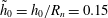
The decisive parameter for the occurrence of cavitation is the tensile strength of the nuclei from which the bubbles grow. We therefore have to model these nuclei. Free gas bubbles in water dissolve or grow due to diffusion of non-condensable gas out of the bubbles or into the bubbles (Epstein & Plesset Reference Epstein and Plesset1950), unless somehow stabilized. Such stabilization was shown by Johnson & Cooke (Reference Johnson and Cooke1981) to be possible for free gas bubbles in seawater, some of which were stabilized by a surface skin, as originally suggested by Fox & Herzfeld (Reference Fox and Herzfeld1954). Yount (Reference Yount1997) assumed the skin to be composed of amphiphilic molecules which allowed diffusion of gas, and the non-spherical shapes of Johnson and Cooke’s stabilized gas nuclei show that skin-stabilized gas bubbles are actually in diffusion balance with the surrounding liquid. Calculations show that such a skin-stabilized bubble has a critical radius in principle equivalent to that of a skin-free bubble of the same gas content. Although the latter is smaller and unstable, their critical radii and pressures can be determined from the same equations (Blake Reference Blake1949; Mørch Reference Mørch2007). Undoubtedly, cavitation nuclei at normal solid boundaries as well as on the surface of particles in the bulk of plain water are also skin-stabilized, and an analysis by Ducker (Reference Ducker2009) supports this expectation. Surface nanobubbles can be observed with atomic force microscopy and are always found to be very flat, with contact radii of up to 1000 nm and heights of up to 50 nm (Zhang, Quinn & Ducker Reference Zhang, Quinn and Ducker2008; Seddon & Lohse Reference Seddon and Lohse2011).

Figure 1. (a) Skin-stabilized interfacial cavitation nucleus in equilibrium on a solid surface,
 $p_{\infty ,0}=p_{g,0}+p_{v}$
. (b) The nucleus when exposed to tensile stress,
$p_{\infty ,0}=p_{g,0}+p_{v}$
. (b) The nucleus when exposed to tensile stress,
 $p_{\infty }<p_{\infty ,0}$
, expanding quasi-statically towards the critical radius of curvature.
$p_{\infty }<p_{\infty ,0}$
, expanding quasi-statically towards the critical radius of curvature.
Let us apply the considerations of Mørch (Reference Mørch2007) to a planar solid–water interface with a stable interfacial gas bubble, shaped as a spherical cap of attachment radius
 $R_{n}$
and height
$R_{n}$
and height
 $h_{0}$
, the bubble being covered by an amphiphilic skin that allows gas diffusion balance at the water–gas interface, i.e. surface tension
$h_{0}$
, the bubble being covered by an amphiphilic skin that allows gas diffusion balance at the water–gas interface, i.e. surface tension
 ${\it\gamma}_{eff,0}=0$
, figure 1(a). Thus, the gas and vapour pressure
${\it\gamma}_{eff,0}=0$
, figure 1(a). Thus, the gas and vapour pressure
 $p_{g,0}+p_{v}$
inside the bubble equals the far-field pressure
$p_{g,0}+p_{v}$
inside the bubble equals the far-field pressure
 $p_{\infty ,0}$
, and the gas density is
$p_{\infty ,0}$
, and the gas density is
 ${\it\rho}_{g,0}$
. During quasi-static reduction of the far-field pressure we assume the nucleus to be pinned along its radius of contact, i.e. that
${\it\rho}_{g,0}$
. During quasi-static reduction of the far-field pressure we assume the nucleus to be pinned along its radius of contact, i.e. that
 $R_{n}$
is constant, but the skin breaks when the bubble surface expands, and skin-free areas with the surface tension of pure water,
$R_{n}$
is constant, but the skin breaks when the bubble surface expands, and skin-free areas with the surface tension of pure water,
 ${\it\gamma}$
, are formed, figure 1(b). During expansion the momentary surface area of the bubble,
${\it\gamma}$
, are formed, figure 1(b). During expansion the momentary surface area of the bubble,
 $$\begin{eqnarray}A={\rm\pi}(R_{n}^{2}+h^{2}),\end{eqnarray}$$
determines its effective surface tension coefficient
 $$\begin{eqnarray}{\it\gamma}_{eff}={\it\gamma}\frac{h^{2}-h_{0}^{2}}{R_{n}^{2}+h^{2}}.\end{eqnarray}$$
The momentary gas pressure in the bubble,
 $p_{g}$
, is governed by the bubble volume
$p_{g}$
, is governed by the bubble volume
 $$\begin{eqnarray}V=\frac{{\rm\pi}}{6}h(3R_{n}^{2}+h^{2}),\end{eqnarray}$$
and for isothermal expansion of a constant mass of gas
 $$\begin{eqnarray}p_{g}=p_{g,0}\frac{h_{0}(3R_{n}^{2}+h_{0}^{2})}{h(3R_{n}^{2}+h^{2})}.\end{eqnarray}$$
With the Laplace pressure we find
 $$\begin{eqnarray}p_{\infty }-p_{v}=p_{g}-\frac{2{\it\gamma}_{eff}}{R}=p_{g,0}\frac{h_{0}(3R_{n}^{2}+h_{0}^{2})}{h(3R_{n}^{2}+h^{2})}-4{\it\gamma}\frac{(h^{2}-h_{0}^{2})h}{(R_{n}^{2}+h^{2})^{2}},\end{eqnarray}$$
where
 $R$
is the radius of curvature of the bubble. The critical far-field pressure is reached when
$R$
is the radius of curvature of the bubble. The critical far-field pressure is reached when
 $\text{d}(p_{\infty }-p_{v})/\text{d}h=0$
, and with
$\text{d}(p_{\infty }-p_{v})/\text{d}h=0$
, and with
 $\tilde{h}=h/R_{n}$
we find from (2.5) that
$\tilde{h}=h/R_{n}$
we find from (2.5) that
 $$\begin{eqnarray}\frac{3p_{g,0}R_{n}}{4{\it\gamma}}=-\left.\frac{\tilde{h}^{2}(3+\tilde{h}^{2})^{2}[3\tilde{h}^{2}(1+\tilde{h}_{0}^{2})-\tilde{h}_{0}^{2}-\tilde{h}^{4}]}{\tilde{h}_{0}(3+\tilde{h}_{0}^{2})(1+\tilde{h}^{2})^{4}}\right|_{h=h_{crit}},\end{eqnarray}$$
which gives
 $h_{crit}$
at given
$h_{crit}$
at given
 $R_{n}$
, while the critical far-field pressure becomes
$R_{n}$
, while the critical far-field pressure becomes
 $$\begin{eqnarray}p_{\infty ,crit}-p_{v}=\left.-\frac{4{\it\gamma}\tilde{h}}{3R_{n}}\left(\frac{(3+\tilde{h}^{2})(3\tilde{h}^{2}(1+\tilde{h}_{0}^{2})-\tilde{h}_{0}^{2}-\tilde{h}^{4})}{(1+\tilde{h}^{2})^{4}}+3\frac{\tilde{h}^{2}-\tilde{h}_{0}^{2}}{(1+\tilde{h}^{2})^{2}}\right)\right|_{h=h_{crit}}.\end{eqnarray}$$
The skin-stabilized interfacial bubble in figure 1(a) is chosen to have a contact angle of
 $17^{\circ }$
at the rim (note that this is measured in the gas), as typical of surface nanobubbles, which gives
$17^{\circ }$
at the rim (note that this is measured in the gas), as typical of surface nanobubbles, which gives
 $\tilde{h}_{0}=0.15$
. For this bubble shape the tensile strength
$\tilde{h}_{0}=0.15$
. For this bubble shape the tensile strength
 $TS$
, defined by
$TS$
, defined by
 $$\begin{eqnarray}TS=p_{v}-p_{\infty ,crit}=\frac{2{\it\gamma}}{R}-p_{g,crit},\end{eqnarray}$$
is shown in figure 2 versus the bubble contact radius
 $R_{n}$
. We notice that the values of tensile strength smaller than
$R_{n}$
. We notice that the values of tensile strength smaller than
 $1~\text{bar}$
usually measured for plain water are obtained for cavitation nuclei of
$1~\text{bar}$
usually measured for plain water are obtained for cavitation nuclei of
 $R_{n}>1~{\rm\mu}\text{m}$
. From the definition of tensile strength
$R_{n}>1~{\rm\mu}\text{m}$
. From the definition of tensile strength
 $TS$
it is apparent that large vapour bubbles have no tensile strength as
$TS$
it is apparent that large vapour bubbles have no tensile strength as
 $p_{g}=0$
and
$p_{g}=0$
and
 ${\it\gamma}/R$
is negligible. Moreover, at low temperature the critical pressure of such bubbles is close to zero, and slightly positive, while water at the boiling point and at atmospheric pressure has a critical pressure of 1 bar. When the skin breaks at bubble expansion, and surface areas of clean water–gas are created, the contact angle of the bubble gradually shifts from a very low value to much higher ones before inception occurs, figure 1. Therefore, the above assumption of a constant
${\it\gamma}/R$
is negligible. Moreover, at low temperature the critical pressure of such bubbles is close to zero, and slightly positive, while water at the boiling point and at atmospheric pressure has a critical pressure of 1 bar. When the skin breaks at bubble expansion, and surface areas of clean water–gas are created, the contact angle of the bubble gradually shifts from a very low value to much higher ones before inception occurs, figure 1. Therefore, the above assumption of a constant
 $R_{n}$
during bubble growth is expected to break down, and
$R_{n}$
during bubble growth is expected to break down, and
 $R_{n}$
actually grows, causing reduction of the tensile strength of the bubble. Further, the assumption of a constant mass in the expanding bubble is challenged, in particular in flow systems where the pressure change is slow, e.g. at ship propellers. Likewise, if a cavitation nucleus is exposed repeatedly to tensile stress, but does not reach inception, it retracts to the same location, but its gas content is increased, and its tensile strength is reduced in each stressing event. When inception has occurred, the gas in the bubble and the skin on its surface are removed from the location of inception because the collapse of the cavitation bubble is violent and usually occurs at a location away from that of the initial cavitation nucleus. This means that after a cavitation event the original cavitation nucleus most probably is eliminated, but the ingredients, i.e. skin, water, gas and solid surfaces, for formation of a new nucleus still exist and it may develop somewhere.
$R_{n}$
actually grows, causing reduction of the tensile strength of the bubble. Further, the assumption of a constant mass in the expanding bubble is challenged, in particular in flow systems where the pressure change is slow, e.g. at ship propellers. Likewise, if a cavitation nucleus is exposed repeatedly to tensile stress, but does not reach inception, it retracts to the same location, but its gas content is increased, and its tensile strength is reduced in each stressing event. When inception has occurred, the gas in the bubble and the skin on its surface are removed from the location of inception because the collapse of the cavitation bubble is violent and usually occurs at a location away from that of the initial cavitation nucleus. This means that after a cavitation event the original cavitation nucleus most probably is eliminated, but the ingredients, i.e. skin, water, gas and solid surfaces, for formation of a new nucleus still exist and it may develop somewhere.

Figure 2. Relationship between the tensile strength
 $TS$
of a skin-stabilized interfacial cavitation nucleus and its radius of attachment
$TS$
of a skin-stabilized interfacial cavitation nucleus and its radius of attachment
 $R_{n}$
for the case of
$R_{n}$
for the case of
 $\tilde{h}_{0}=h_{0}/R_{n}=0.15$
.
$\tilde{h}_{0}=h_{0}/R_{n}=0.15$
.
2.2. Nuclei exposed to pressure increase
If the interfacial cavitation bubble configuration in figure 3(a) is exposed to a steep increase of the far-field pressure from
 $p_{\infty ,0}$
to
$p_{\infty ,0}$
to
 $p_{\infty ,C}$
it collapses as shown in figure 3(b), the collapse proceeding from its rim of attachment on the solid surface towards the bubble centre, where its original gas content
$p_{\infty ,C}$
it collapses as shown in figure 3(b), the collapse proceeding from its rim of attachment on the solid surface towards the bubble centre, where its original gas content
 ${\it\rho}_{g,0}V_{0}$
is concentrated in a spherical bubble of radius
${\it\rho}_{g,0}V_{0}$
is concentrated in a spherical bubble of radius
 $R_{sph,0}$
. The skin on the bubble surface outside a central area of approximately
$R_{sph,0}$
. The skin on the bubble surface outside a central area of approximately
 ${\rm\pi}R_{sph}^{2}$
is left on the solid surface. We estimate that the sphere itself has a surface coverage of skin
${\rm\pi}R_{sph}^{2}$
is left on the solid surface. We estimate that the sphere itself has a surface coverage of skin
 ${\it\alpha}_{0}$
of approximately 25 % when formed at
${\it\alpha}_{0}$
of approximately 25 % when formed at
 $t=0$
, resulting in
$t=0$
, resulting in
 ${\it\gamma}_{eff,sph,0}=(1-{\it\alpha}_{0}){\it\gamma}\approx 0.75{\it\gamma}$
.
${\it\gamma}_{eff,sph,0}=(1-{\it\alpha}_{0}){\it\gamma}\approx 0.75{\it\gamma}$
.
Conservation of the mass of gas in the collapsed interfacial bubble gives
 $$\begin{eqnarray}{\it\rho}_{g,0}V_{0}={\textstyle \frac{4}{3}}{\rm\pi}{\it\rho}_{g,sph,0}R_{sph,0}^{3},\end{eqnarray}$$
where
 ${\it\rho}_{g,sph,0}$
is the density of the gas in the spherical bubble, formed at
${\it\rho}_{g,sph,0}$
is the density of the gas in the spherical bubble, formed at
 $t=0$
. The pressure inside this bubble
$t=0$
. The pressure inside this bubble
 $$\begin{eqnarray}p_{g,sph,0}+p_{v}=p_{\infty ,C}+\frac{2{\it\gamma}_{eff,sph,0}}{R_{sph,0}}.\end{eqnarray}$$
With the isothermal condition we then obtain
 $$\begin{eqnarray}{\it\rho}_{g,sph,0}={\it\rho}_{g,0}\frac{p_{\infty ,C}-p_{v}+2{\it\gamma}_{eff,sph,0}/R_{sph,0}}{p_{g,0}},\end{eqnarray}$$
and with (2.3) and (2.9) we find that
 $$\begin{eqnarray}\frac{1}{8}h_{0}(3R_{n}^{2}+h_{0}^{2})=\frac{R_{sph,0}^{3}}{p_{g,0}}\left(p_{\infty ,C}-p_{v}+\frac{2{\it\gamma}_{eff,sph,0}}{R_{sph,0}}\right),\end{eqnarray}$$
which allows us to calculate
 $R_{sph,0}$
when the initial interfacial nucleus is given.
$R_{sph,0}$
when the initial interfacial nucleus is given.

Figure 3. (a) The skin-stabilized interfacial cavitation nucleus in figure 1(a) just before the arrival of the front of a compression wave at
 $t=0$
, raising the far-field pressure to a higher level,
$t=0$
, raising the far-field pressure to a higher level,
 $p_{\infty ,C}$
. (b) The pressure increase transforms the flat spherically shaped cap into a spherical bubble that is partially skin-covered and of radius
$p_{\infty ,C}$
. (b) The pressure increase transforms the flat spherically shaped cap into a spherical bubble that is partially skin-covered and of radius
 $R_{sph,0}$
, the initial skin coverage factor being
$R_{sph,0}$
, the initial skin coverage factor being
 ${\it\alpha}_{0}$
, the rest of the skin being left on the solid surface. (c) If exposed to tensile stress the spherical bubble expands, but the area of skin remains constant. Thus,
${\it\alpha}_{0}$
, the rest of the skin being left on the solid surface. (c) If exposed to tensile stress the spherical bubble expands, but the area of skin remains constant. Thus,
 ${\it\alpha}$
is reduced, and the bubble eventually reaches critical conditions.
${\it\alpha}$
is reduced, and the bubble eventually reaches critical conditions.
The critical radius and pressure for the initial spherical bubble, covered partially with a skin at the coverage factor
 ${\it\alpha}_{0}$
, are found by reducing the far-field pressure
${\it\alpha}_{0}$
, are found by reducing the far-field pressure
 $p_{\infty }$
quasi-statically until inception, assuming a constant gas content (Blake Reference Blake1949; Mørch Reference Mørch2007). The area of skin on the initial bubble is
$p_{\infty }$
quasi-statically until inception, assuming a constant gas content (Blake Reference Blake1949; Mørch Reference Mørch2007). The area of skin on the initial bubble is
 $$\begin{eqnarray}A_{skin}=4{\rm\pi}{\it\alpha}_{0}R_{sph,0}^{2},\end{eqnarray}$$
and
 $A_{skin}$
remains constant during bubble expansion. The effective surface tension becomes
$A_{skin}$
remains constant during bubble expansion. The effective surface tension becomes
 $$\begin{eqnarray}{\it\gamma}_{eff}={\it\gamma}(1-{\it\alpha}_{0}(R_{sph,0}/R_{sph})^{2}),\end{eqnarray}$$
and the gas pressure in the bubble
 $$\begin{eqnarray}p_{g,sph}=p_{g,sph,0}\left(\frac{R_{sph,0}}{R_{sph}}\right)^{3}.\end{eqnarray}$$
With the pressure jump across the bubble surface
 $$\begin{eqnarray}{\rm\Delta}p=p_{g,sph}+p_{v}-p_{\infty }=\frac{2{\it\gamma}_{eff}}{R_{sph}}=\frac{2{\it\gamma}}{R_{\text{H}_{2}\text{O}}},\end{eqnarray}$$
where
 $R_{\text{H}_{2}\text{O}}$
is the curvature of the areas of pure water on the bubble surface, we obtain with (2.14)
$R_{\text{H}_{2}\text{O}}$
is the curvature of the areas of pure water on the bubble surface, we obtain with (2.14)
 $$\begin{eqnarray}R_{\text{H}_{2}\text{O}}=\frac{R_{sph}^{3}}{R_{sph}^{2}-{\it\alpha}_{0}R_{sph,0}^{2}}.\end{eqnarray}$$
Critical conditions are met when
 $$\begin{eqnarray}\frac{\text{d}(p_{\infty }-p_{v})}{\text{d}R_{sph}}=\frac{\text{d}(p_{g,sph}-{\rm\Delta}p)}{\text{d}R_{sph}}=0,\end{eqnarray}$$
and we find that
 $$\begin{eqnarray}\left(\frac{R_{sph,crit,0}}{R_{sph,0}}\right)^{2}=3\left[{\it\alpha}_{0}+\frac{p_{g,sph,0}R_{sph,0}}{2{\it\gamma}}\right].\end{eqnarray}$$
With (2.15), (2.16) and (2.19) we finally obtain the tensile strength
 $$\begin{eqnarray}TS_{sph,0}=\frac{2{\it\gamma}}{R_{sph,crit,0}}\left(1-{\it\alpha}_{0}\left(\frac{R_{sph,0}}{R_{sph,crit,0}}\right)^{2}\right)-p_{g,sph,0}\left(\frac{R_{sph,0}}{R_{sph,crit,0}}\right)^{3}.\end{eqnarray}$$

Figure 4. Lower curve (blue): initial radius of the spherical bubble
 $R_{sph,0}$
versus the pressurization pressure
$R_{sph,0}$
versus the pressurization pressure
 $p_{\infty ,C}-p_{v}$
. Middle curve (green): critical bubble radius
$p_{\infty ,C}-p_{v}$
. Middle curve (green): critical bubble radius
 $R_{sph,crit}$
. Upper curve (brown): tensile strength
$R_{sph,crit}$
. Upper curve (brown): tensile strength
 $TS_{sph,0}$
of this bubble, initially skin-covered by
$TS_{sph,0}$
of this bubble, initially skin-covered by
 ${\it\alpha}_{0}=0.25$
.
${\it\alpha}_{0}=0.25$
.
Equations (2.19) and (2.20) allow us to calculate
 $R_{sph,crit,0}$
and
$R_{sph,crit,0}$
and
 $TS_{sph,0}$
at the moment when the spherical bubble of radius
$TS_{sph,0}$
at the moment when the spherical bubble of radius
 $R_{sph,0}$
is formed. As an example we consider the case of an initial cavitation nucleus with
$R_{sph,0}$
is formed. As an example we consider the case of an initial cavitation nucleus with
 $R_{n}=1.6~{\rm\mu}\text{m}$
and
$R_{n}=1.6~{\rm\mu}\text{m}$
and
 $h_{0}=0.24~{\rm\mu}\text{m}$
, figure 3(a), which has a tensile strength of approximately 0.5 bar. It is abruptly pressurized from
$h_{0}=0.24~{\rm\mu}\text{m}$
, figure 3(a), which has a tensile strength of approximately 0.5 bar. It is abruptly pressurized from
 $p_{\infty ,0}-p_{v}=1~\text{bar}$
to
$p_{\infty ,0}-p_{v}=1~\text{bar}$
to
 $p_{\infty ,C}-p_{v}=2~\text{bar}$
, and we find, using
$p_{\infty ,C}-p_{v}=2~\text{bar}$
, and we find, using
 ${\it\gamma}_{eff,sph}\approx 0.75{\it\gamma}$
in (2.12), that the radius of the spherical bubble
${\it\gamma}_{eff,sph}\approx 0.75{\it\gamma}$
in (2.12), that the radius of the spherical bubble
 $R_{sph,0}=0.35~{\rm\mu}\text{m}$
, and the gas pressure in it
$R_{sph,0}=0.35~{\rm\mu}\text{m}$
, and the gas pressure in it
 $p_{g,sph,0}=5.1~\text{bar}$
,
$p_{g,sph,0}=5.1~\text{bar}$
,
 $R_{sph,crit,0}=0.75~{\rm\mu}\text{m}$
and
$R_{sph,crit,0}=0.75~{\rm\mu}\text{m}$
and
 $TS=1.29~\text{bar}$
. Thus, pressurization by 1 bar has increased the tensile strength of the original interfacial bubble from 0.5 to 1.3 bar. From figure 4 it is apparent that the level of pressurization is of minor importance. At fast pressure rise from
$TS=1.29~\text{bar}$
. Thus, pressurization by 1 bar has increased the tensile strength of the original interfacial bubble from 0.5 to 1.3 bar. From figure 4 it is apparent that the level of pressurization is of minor importance. At fast pressure rise from
 $p_{\infty ,0}$
to
$p_{\infty ,0}$
to
 $p_{\infty ,C}$
it is the transformation of the nucleus at constant gas content from being a spherical cap on the solid–water interface into a sphere that is decisive for the immediate increase of tensile strength. However, the gas in the skin-covered spherical bubble is at a high pressure, and it is not in diffusion balance. Therefore, after its formation it cannot maintain a constant gas content.
$p_{\infty ,C}$
it is the transformation of the nucleus at constant gas content from being a spherical cap on the solid–water interface into a sphere that is decisive for the immediate increase of tensile strength. However, the gas in the skin-covered spherical bubble is at a high pressure, and it is not in diffusion balance. Therefore, after its formation it cannot maintain a constant gas content.
According to Epstein & Plesset (Reference Epstein and Plesset1950), a bubble in water of radius like the one considered above, but without elements of skin on its surface and exposed to atmospheric pressure only, dissolves completely within approximately 2 ms due to surface tension. The reduced surface tension of our spherical bubble prolongs its time of dissolution, but the elevated far-field pressure has an opposite effect. With
 ${\it\gamma}_{eff,sph}\approx 0.75{\it\gamma}$
an increase of the tensile strength beyond the one calculated above is expected within a time of the order of ms. The partial coverage with skin puts a limit on the shrinking of the spherical bubble, and it ends up being fully skin-covered and in diffusion balance with the surrounding liquid – unless the skin collapses due to the pressurization (Johnson & Cooke Reference Johnson and Cooke1981). If so, the skin is most probably deposited on the solid surface where it may form a new skin-stabilized interfacial bubble of size much smaller than the original one, and therefore of much higher tensile strength.
${\it\gamma}_{eff,sph}\approx 0.75{\it\gamma}$
an increase of the tensile strength beyond the one calculated above is expected within a time of the order of ms. The partial coverage with skin puts a limit on the shrinking of the spherical bubble, and it ends up being fully skin-covered and in diffusion balance with the surrounding liquid – unless the skin collapses due to the pressurization (Johnson & Cooke Reference Johnson and Cooke1981). If so, the skin is most probably deposited on the solid surface where it may form a new skin-stabilized interfacial bubble of size much smaller than the original one, and therefore of much higher tensile strength.
3. Experimental set-up
Experiments were carried out at room temperature in a water-filled container at atmospheric conditions (figure 5). The container consisted of a vertical circularly cylindrical PMMA tube (inner/outer diameters
 $90/100~\text{mm}$
) which had an aluminium bottom with a spherical inner surface shape (radius of curvature 50 mm). An aluminium rod (diameter 15 mm, length
$90/100~\text{mm}$
) which had an aluminium bottom with a spherical inner surface shape (radius of curvature 50 mm). An aluminium rod (diameter 15 mm, length
 $450~\text{mm}$
) with a brass end stop was mounted axially beneath the bottom. When filled with 1500 ml of water this system had a mass
$450~\text{mm}$
) with a brass end stop was mounted axially beneath the bottom. When filled with 1500 ml of water this system had a mass
 $M=3.7~\text{kg}$
. Further, a brass weight of mass
$M=3.7~\text{kg}$
. Further, a brass weight of mass
 $m$
was placed on the rod so that it could be displaced freely between the end stop and an adjustable upper stop. The container,
$m$
was placed on the rod so that it could be displaced freely between the end stop and an adjustable upper stop. The container,
 $M$
, was mounted in a rig so that it could be displaced vertically relative to the rig floor. Beneath the container, a circularly cylindrical steel block with a hole of 90 mm diameter (i.e. smaller than the cylindrical bottom) and with a mass of
$M$
, was mounted in a rig so that it could be displaced vertically relative to the rig floor. Beneath the container, a circularly cylindrical steel block with a hole of 90 mm diameter (i.e. smaller than the cylindrical bottom) and with a mass of
 $M_{block}=4.6~\text{kg}$
was carried by a magnetic holder
$M_{block}=4.6~\text{kg}$
was carried by a magnetic holder
 $H$
mounted on the rig floor.
$H$
mounted on the rig floor.

Figure 5. Experimental set-up for measurement of the tensile strength of water, here shown when ready for delivery of a
 $C$
-pulse followed by a
$C$
-pulse followed by a
 $T$
-pulse – a
$T$
-pulse – a
 $CT$
-pulse.
$CT$
-pulse.
When a compression pulse (
 $C$
-pulse) followed by a tension pulse (
$C$
-pulse) followed by a tension pulse (
 $T$
-pulse) in the water-filled container was prepared (
$T$
-pulse) in the water-filled container was prepared (
 $CT$
-pulse), the upper stop on the rod was fixed in a desired position
$CT$
-pulse), the upper stop on the rod was fixed in a desired position
 $h_{m}$
above the weight
$h_{m}$
above the weight
 $m$
that rested on the end stop. Then the water-filled container
$m$
that rested on the end stop. Then the water-filled container
 $M$
was positioned with the system lock at a level
$M$
was positioned with the system lock at a level
 $h_{M}$
above
$h_{M}$
above
 $M_{block}$
(figure 5). Finally, the mass
$M_{block}$
(figure 5). Finally, the mass
 $m$
was lifted up to the upper stop, the system lock was released, and the whole system dropped due to gravity. The bottom rim of
$m$
was lifted up to the upper stop, the system lock was released, and the whole system dropped due to gravity. The bottom rim of
 $M$
impacted
$M$
impacted
 $M_{block}$
circumferentially with a velocity of
$M_{block}$
circumferentially with a velocity of
 $v_{M}=\sqrt{2gh_{M}}$
after a time
$v_{M}=\sqrt{2gh_{M}}$
after a time
 ${\it\tau}_{M}=\sqrt{2h_{M}/g}$
, which abruptly stopped the downward motion of
${\it\tau}_{M}=\sqrt{2h_{M}/g}$
, which abruptly stopped the downward motion of
 $M$
, and an annular
$M$
, and an annular
 $C$
-pulse was produced at the rim of the container bottom, while
$C$
-pulse was produced at the rim of the container bottom, while
 $M_{block}$
was shot off onto the rig floor. The mass
$M_{block}$
was shot off onto the rig floor. The mass
 $m$
continued falling the distance
$m$
continued falling the distance
 $h_{m}$
along the rod until impact on the end stop, in principle with a velocity of
$h_{m}$
along the rod until impact on the end stop, in principle with a velocity of
 $v_{m}\approx \sqrt{2g(h_{M}+h_{m})}$
at a time
$v_{m}\approx \sqrt{2g(h_{M}+h_{m})}$
at a time
 ${\it\tau}_{m}\approx \sqrt{2(h_{M}+h_{m})/g}$
after the system release, thereby producing a
${\it\tau}_{m}\approx \sqrt{2(h_{M}+h_{m})/g}$
after the system release, thereby producing a
 $T$
-pulse in the rod. For small
$T$
-pulse in the rod. For small
 $h_{m}$
the system deformations complicated these formulae, the end stop vibrating due to the
$h_{m}$
the system deformations complicated these formulae, the end stop vibrating due to the
 $M$
-impact when the
$M$
-impact when the
 $m$
-impact took place. Therefore, it was difficult to reproduce
$m$
-impact took place. Therefore, it was difficult to reproduce
 ${\it\tau}_{m}$
in subsequent experiments. The
${\it\tau}_{m}$
in subsequent experiments. The
 $T$
-pulse arrived at the centre of the bottom–water interface with a delay of
$T$
-pulse arrived at the centre of the bottom–water interface with a delay of
 ${\it\tau}_{L}\approx 90~{\rm\mu}\text{s}$
, i.e. at a time
${\it\tau}_{L}\approx 90~{\rm\mu}\text{s}$
, i.e. at a time
 $t={\it\tau}_{m}-{\it\tau}_{M}+{\it\tau}_{L}$
after the
$t={\it\tau}_{m}-{\it\tau}_{M}+{\it\tau}_{L}$
after the
 $M$
-impact. To produce only a tension pulse (
$M$
-impact. To produce only a tension pulse (
 $T$
-pulse),
$T$
-pulse),
 $M_{block}$
was removed, and the system
$M_{block}$
was removed, and the system
 $M$
was allowed to rest on the spring
$M$
was allowed to rest on the spring
 $S$
. Then the mass
$S$
. Then the mass
 $m$
was released from a desired height
$m$
was released from a desired height
 $h_{m}$
above the end stop, impacting it with the velocity
$h_{m}$
above the end stop, impacting it with the velocity
 $v_{m}=\sqrt{2gh_{m}}$
.
$v_{m}=\sqrt{2gh_{m}}$
.
The pressure pulses in the water were monitored with a Brüel & Kjær (B&K) 8103 hydrophone (resonance frequency 140 kHz, upper frequency of amplifier filter
 ${>}100$
or 3 kHz) positioned axially at a distance
${>}100$
or 3 kHz) positioned axially at a distance
 $h_{p}$
above the centre of the bottom. The acoustic centre of the hydrophone was a further 11 mm higher up. These hydrophone signals revealed the local features of the pressure field at some distance from the cavitation events studied, not the tensile stresses actually governing the cavity growth and collapse on and near to the bottom. A B&K 8309 accelerometer, mounted on the end stop, was used to identify the time and strength of the
$h_{p}$
above the centre of the bottom. The acoustic centre of the hydrophone was a further 11 mm higher up. These hydrophone signals revealed the local features of the pressure field at some distance from the cavitation events studied, not the tensile stresses actually governing the cavity growth and collapse on and near to the bottom. A B&K 8309 accelerometer, mounted on the end stop, was used to identify the time and strength of the
 $m$
-impact.
$m$
-impact.
The cavitation bubbles were recorded with a Phantom v4.2 digital video camera, focused on the bottom centre, where maximum values of tensile stress were achieved. The camera angle with the horizontal plane was
 $45^{\circ }$
, which allowed observation of cavities growing on and just above the bottom near to the axis of symmetry at an angle of approximately
$45^{\circ }$
, which allowed observation of cavities growing on and just above the bottom near to the axis of symmetry at an angle of approximately
 $32^{\circ }$
. Illumination with a flashlamp was arranged in a similar way from the opposite side. For data recording by
$32^{\circ }$
. Illumination with a flashlamp was arranged in a similar way from the opposite side. For data recording by
 $T$
-pulses the flashlight was triggered at
$T$
-pulses the flashlight was triggered at
 $m$
-impact on the end stop and it opened a circuit with a photodiode that triggered a four-channel digital storage oscilloscope. Data recording by
$m$
-impact on the end stop and it opened a circuit with a photodiode that triggered a four-channel digital storage oscilloscope. Data recording by
 $CT$
-pulses was triggered at
$CT$
-pulses was triggered at
 $M$
-impact on
$M$
-impact on
 $M_{block}$
. The camera was run at 25 000 f.p.s., each of
$M_{block}$
. The camera was run at 25 000 f.p.s., each of
 $128\;\text{pixels}\times 128\;\text{pixels}$
.
$128\;\text{pixels}\times 128\;\text{pixels}$
.
Due to the cylindrical shape of the water-filled container, structures present in the water appear optically distorted when observed from the outside. Thus, bubbles formed near the axis of symmetry and in the picture plane through this axis appear horizontally elongated by a factor equal to the index of refraction, while at the front wall no distortion occurs. Thus, the distortion of bulk water bubbles can be used for determining the position of the bubbles in the direction of observation. They are ellipsoidal, reflect flash light from their top, and also weakly from their bottom, and produce no visible shadows on the container bottom. Bubbles on the container bottom appear ellipsoidal, but produce a narrow shadow on the bottom at their rim of contact.
The
 $M$
-impact waves, generated circumferentially at the underside of the container bottom, and the
$M$
-impact waves, generated circumferentially at the underside of the container bottom, and the
 $m$
-impact waves, arriving centrally via the rod, propagated as rotationally symmetric longitudinal and transverse waves to the bottom–water interface. The momentary motion of the elements of the inner bottom surface produced the pressure waves in the water. The spherical shape of this interface would have focused the pressure waves at its centre of curvature
$m$
-impact waves, arriving centrally via the rod, propagated as rotationally symmetric longitudinal and transverse waves to the bottom–water interface. The momentary motion of the elements of the inner bottom surface produced the pressure waves in the water. The spherical shape of this interface would have focused the pressure waves at its centre of curvature
 $F$
if emitted simultaneously from all surface elements (as in piezo-electrically driven medical lithotripters), but in the present purely mechanical pulse generator only wave contributions from annular surface elements of the same radius arrived simultaneously, resulting in elevated pressure amplitudes axially. In the water column, which had a height of 245 mm measured from the centre of the bottom, the pressure waves propagated to the free water surface. Here they were reflected with a phase shift of
$F$
if emitted simultaneously from all surface elements (as in piezo-electrically driven medical lithotripters), but in the present purely mechanical pulse generator only wave contributions from annular surface elements of the same radius arrived simultaneously, resulting in elevated pressure amplitudes axially. In the water column, which had a height of 245 mm measured from the centre of the bottom, the pressure waves propagated to the free water surface. Here they were reflected with a phase shift of
 ${\rm\pi}$
, returned to the bottom, and were again reflected, but with negligible phase shift. Maxima of compressive and tensile stress were achieved axially on the bottom–water interface. At sufficient
${\rm\pi}$
, returned to the bottom, and were again reflected, but with negligible phase shift. Maxima of compressive and tensile stress were achieved axially on the bottom–water interface. At sufficient
 $m$
-impact momentum, a
$m$
-impact momentum, a
 $T$
-pulse made the weakest cavitation nuclei expand beyond critical size, and vaporous cavitation bubbles were generated, but high-frequency resonance oscillations (HF oscillations) generated by the
$T$
-pulse made the weakest cavitation nuclei expand beyond critical size, and vaporous cavitation bubbles were generated, but high-frequency resonance oscillations (HF oscillations) generated by the
 $M$
-impacts were also found to act as cavitation generators.
$M$
-impacts were also found to act as cavitation generators.
The equipment was simply cleaned prior to use, i.e. on a macromolecular scale all equipment surfaces were contaminated, and a number of particles had entered the Elix water, taken from our clean water tank where it had been stored at atmospheric pressure, thereby allowing for occasional cavitation events off the bottom surface. Water was filled into the PMMA cylinder 1–4 h before the experiments.
4. Tensile strength calculation
The growth and collapse of a gas bubble in water are governed by the far-field pressure
 $p_{\infty }$
, and the bubble radius
$p_{\infty }$
, and the bubble radius
 $R$
is described by the Rayleigh–Plesset equation (Brennen Reference Brennen1995). By studying the tensile strength of water experimentally we can record the bubble growth using high-speed imaging, but we do not know very well where and when a cavitation nucleus turns supercritical. To catch the bubbles formed, a relatively large field of view is needed, and it limits the resolution and the frame rate. Not until the nuclei have grown notably beyond critical size is it possible to record the bubbles. At this stage the surface tension term as well as the viscosity term is without importance due to the supercritical bubble size. Thus, the Rayleigh–Plesset equation reduces to the classical Rayleigh equation
$R$
is described by the Rayleigh–Plesset equation (Brennen Reference Brennen1995). By studying the tensile strength of water experimentally we can record the bubble growth using high-speed imaging, but we do not know very well where and when a cavitation nucleus turns supercritical. To catch the bubbles formed, a relatively large field of view is needed, and it limits the resolution and the frame rate. Not until the nuclei have grown notably beyond critical size is it possible to record the bubbles. At this stage the surface tension term as well as the viscosity term is without importance due to the supercritical bubble size. Thus, the Rayleigh–Plesset equation reduces to the classical Rayleigh equation
 $$\begin{eqnarray}p_{v}-p_{\infty }={\it\rho}\left({\textstyle \frac{3}{2}}{\dot{R}}^{2}+R\ddot{R}\right),\end{eqnarray}$$
where
 ${\it\rho}$
is the density of water. Inception occurs within a single frame and the bubble radii grow almost linearly during the initial frames after inception, where the acceleration term
${\it\rho}$
is the density of water. Inception occurs within a single frame and the bubble radii grow almost linearly during the initial frames after inception, where the acceleration term
 $\ddot{R}$
has just shifted from positive values at inception to negative values after inception. Therefore the acceleration term is negligible just after inception, and the initial bubble growth rate obtained by extrapolation back to
$\ddot{R}$
has just shifted from positive values at inception to negative values after inception. Therefore the acceleration term is negligible just after inception, and the initial bubble growth rate obtained by extrapolation back to
 $R=0$
of the recorded radius versus time curve gives the critical pressure and the tensile strength at the time of inception,
$R=0$
of the recorded radius versus time curve gives the critical pressure and the tensile strength at the time of inception,
 $t=t_{i}$
, by
$t=t_{i}$
, by
 $$\begin{eqnarray}TS=(p_{v}-p_{\infty ,crit})|_{t=t_{i}}={\textstyle \frac{3}{2}}{\it\rho}{\dot{R}}^{2}|_{t=t_{i}}.\end{eqnarray}$$
Determination of the far-field pressure that governs the subsequent bubble development demands (4.1) to be used (Borkent et al. Reference Borkent, Arora, Ohl, de Jong, Versluis, Lohse, Mørch, Klaseboer and Khoo2008), but it is not relevant in the present analysis.

Figure 6. Experiment 4. (a) Hydrophone recording of the
 $T$
-pulse obtained for
$T$
-pulse obtained for
 $P_{m}=1.5~\text{kg}~\text{m}~\text{s}^{-1}$
(top, red); accelerometer signal (middle, blue);
$P_{m}=1.5~\text{kg}~\text{m}~\text{s}^{-1}$
(top, red); accelerometer signal (middle, blue);
 $m$
-impact flash trigger signal (bottom, black). The accelerometer signal and the trigger signal are shown in arbitrary units. The time
$m$
-impact flash trigger signal (bottom, black). The accelerometer signal and the trigger signal are shown in arbitrary units. The time
 $t=0$
at
$t=0$
at
 $T$
-pulse arrival at the bottom centre. (b) Video of the cavitation event. The length of the horizontal scale bar is 2 mm. (c) Bubble radius versus time gives
$T$
-pulse arrival at the bottom centre. (b) Video of the cavitation event. The length of the horizontal scale bar is 2 mm. (c) Bubble radius versus time gives
 $TS_{1}=0.52~\text{bar}$
.
$TS_{1}=0.52~\text{bar}$
.
5. Tension pulses
In the experiments with tension pulses (
 $T$
-pulses) a mass
$T$
-pulses) a mass
 $m=2.0~\text{kg}$
was dropped onto the end stop from heights of
$m=2.0~\text{kg}$
was dropped onto the end stop from heights of
 $30~\text{mm}\leqslant h_{m}\leqslant 180~\text{mm}$
, i.e. the
$30~\text{mm}\leqslant h_{m}\leqslant 180~\text{mm}$
, i.e. the
 $m$
-impact momentum values were
$m$
-impact momentum values were
 $1.5~\text{kg}~\text{m}~\text{s}^{-1}\leqslant P_{m}\leqslant 4.0~\text{kg}~\text{m}~\text{s}^{-1}$
. A compliant ring was placed on the end stop to avoid strong resonance oscillations in the rod, i.e. it prolonged the pulse duration and reduced the peak tension. Examples of accelerometer and hydrophone recordings (frequency range 2 Hz to
$1.5~\text{kg}~\text{m}~\text{s}^{-1}\leqslant P_{m}\leqslant 4.0~\text{kg}~\text{m}~\text{s}^{-1}$
. A compliant ring was placed on the end stop to avoid strong resonance oscillations in the rod, i.e. it prolonged the pulse duration and reduced the peak tension. Examples of accelerometer and hydrophone recordings (frequency range 2 Hz to
 ${>}100$
kHz) obtained with the hydrophone positioned at
${>}100$
kHz) obtained with the hydrophone positioned at
 $h_{p}=10~\text{mm}$
, video recordings of the corresponding cavitation events and graphs of the initial radial growth of numbered characteristic bubbles are shown in figures 6–8.
$h_{p}=10~\text{mm}$
, video recordings of the corresponding cavitation events and graphs of the initial radial growth of numbered characteristic bubbles are shown in figures 6–8.
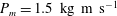
Figure 6 shows a cavitation event produced when
 $P_{m}=1.5~\text{kg}~\text{m}~\text{s}^{-1}$
. Inception occurred from a nucleus of
$P_{m}=1.5~\text{kg}~\text{m}~\text{s}^{-1}$
. Inception occurred from a nucleus of
 $TS_{1}=0.52~\text{bar}$
at the time
$TS_{1}=0.52~\text{bar}$
at the time
 $t_{i}\approx 654~{\rm\mu}\text{s}$
after arrival of the leading edge of the
$t_{i}\approx 654~{\rm\mu}\text{s}$
after arrival of the leading edge of the
 $T$
-pulse at the centre of the container bottom, i.e. close to the maximum of tensile stress in the pulse. When the weakest cavitation nucleus turned supercritical, it exploded into a vaporous cavity, the relaxation wave spreading in the surrounding liquid, its front advancing with the sound velocity of the liquid, its tail with the bubble wall velocity. In the video the cavitation event, figure 6(b), occurs at a damage spot on the bottom. The flashlight strongly reflects from the central area of the white-painted bottom and reveals the surface irregularities.
$T$
-pulse at the centre of the container bottom, i.e. close to the maximum of tensile stress in the pulse. When the weakest cavitation nucleus turned supercritical, it exploded into a vaporous cavity, the relaxation wave spreading in the surrounding liquid, its front advancing with the sound velocity of the liquid, its tail with the bubble wall velocity. In the video the cavitation event, figure 6(b), occurs at a damage spot on the bottom. The flashlight strongly reflects from the central area of the white-painted bottom and reveals the surface irregularities.
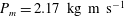
At a higher value of the impact momentum,
 $P_{m}=2.17~\text{kg}~\text{m}~\text{s}^{-1}$
, figure 7, the weakest nucleus was again located at the damage spot, bubble 1. Now
$P_{m}=2.17~\text{kg}~\text{m}~\text{s}^{-1}$
, figure 7, the weakest nucleus was again located at the damage spot, bubble 1. Now
 $TS_{1}=0.53~\text{bar}$
and inception occurred near to the peak of tensile stress at
$TS_{1}=0.53~\text{bar}$
and inception occurred near to the peak of tensile stress at
 $t_{i,1}\approx 357~{\rm\mu}\text{s}$
. The video also shows inception of another cavity, bubble 2, located on the bottom in front of bubble 1. Its nucleus had
$t_{i,1}\approx 357~{\rm\mu}\text{s}$
. The video also shows inception of another cavity, bubble 2, located on the bottom in front of bubble 1. Its nucleus had
 $TS_{2}\approx 0.19~\text{bar}$
at
$TS_{2}\approx 0.19~\text{bar}$
at
 $t_{i,2}\approx 489~{\rm\mu}\text{s}$
. Thus, during the stress relaxation of bubble 1, the nucleus of bubble 2 had shifted its tensile strength from a level higher than
$t_{i,2}\approx 489~{\rm\mu}\text{s}$
. Thus, during the stress relaxation of bubble 1, the nucleus of bubble 2 had shifted its tensile strength from a level higher than
 $TS_{1}$
to
$TS_{1}$
to
 $TS_{2}$
, and exploded into a vaporous cavity. This shows that during exposure to tensile stress, cavitation nuclei lose tensile strength.
$TS_{2}$
, and exploded into a vaporous cavity. This shows that during exposure to tensile stress, cavitation nuclei lose tensile strength.

Figure 7. Experiment 7. (a) Hydrophone recording of the
 $T$
-pulse obtained for
$T$
-pulse obtained for
 $P_{m}=2.17~\text{kg}~\text{m}~\text{s}^{-1}$
(top, red); accelerometer signal (middle, blue);
$P_{m}=2.17~\text{kg}~\text{m}~\text{s}^{-1}$
(top, red); accelerometer signal (middle, blue);
 $m$
-impact flash trigger signal (bottom, black). The accelerometer signal and the trigger signal are shown in arbitrary units. The time
$m$
-impact flash trigger signal (bottom, black). The accelerometer signal and the trigger signal are shown in arbitrary units. The time
 $t=0$
at
$t=0$
at
 $T$
-pulse arrival at the bottom centre. (b) Video of the cavitation event. The length of the horizontal scale bar is 2 mm. (c) Bubble radius versus time for bubble 1 (circles) and bubble 2 (stars) gives
$T$
-pulse arrival at the bottom centre. (b) Video of the cavitation event. The length of the horizontal scale bar is 2 mm. (c) Bubble radius versus time for bubble 1 (circles) and bubble 2 (stars) gives
 $TS_{1}=0.53~\text{bar}$
and
$TS_{1}=0.53~\text{bar}$
and
 $TS_{2}=0.19~\text{bar}$
.
$TS_{2}=0.19~\text{bar}$
.
Repetition of the above experiment 3 min later led to the event presented in figure 8. Here, bubble 1 grew from a nucleus of
 $TS_{1}=0.11~\text{bar}$
at
$TS_{1}=0.11~\text{bar}$
at
 $t_{i,1}\approx 200~{\rm\mu}\text{s}$
, i.e.
$t_{i,1}\approx 200~{\rm\mu}\text{s}$
, i.e.
 ${\approx}250~{\rm\mu}\text{s}$
before peak tensile stress was achieved, and from a position on the bottom
${\approx}250~{\rm\mu}\text{s}$
before peak tensile stress was achieved, and from a position on the bottom
 $600{-}700~{\rm\mu}\text{m}$
from where nucleation and collapse of bubble 2 in the preceding experiment occurred. Its relaxation wave was superseded by the strong
$600{-}700~{\rm\mu}\text{m}$
from where nucleation and collapse of bubble 2 in the preceding experiment occurred. Its relaxation wave was superseded by the strong
 $T$
-pulse which even accelerated the growth of bubble 1. At
$T$
-pulse which even accelerated the growth of bubble 1. At
 $t_{i,2}\approx 382~{\rm\mu}\text{s}$
bubble 2 developed from the same damage spot as bubble 1 of the preceding experiment, now from a nucleus of tensile strength
$t_{i,2}\approx 382~{\rm\mu}\text{s}$
bubble 2 developed from the same damage spot as bubble 1 of the preceding experiment, now from a nucleus of tensile strength
 $TS_{2}=0.34~\text{bar}$
.
$TS_{2}=0.34~\text{bar}$
.

Figure 8. Experiment 8. (a) Hydrophone recording of the
 $T$
-pulse obtained for
$T$
-pulse obtained for
 $P_{m}=2.17~\text{kg}~\text{m}~\text{s}^{-1}$
(top, red); accelerometer signal (middle, blue);
$P_{m}=2.17~\text{kg}~\text{m}~\text{s}^{-1}$
(top, red); accelerometer signal (middle, blue);
 $m$
-impact flash trigger signal (bottom, black). The time
$m$
-impact flash trigger signal (bottom, black). The time
 $t=0$
at
$t=0$
at
 $T$
-pulse arrival at the bottom centre. The accelerometer signal and the trigger signal are shown in arbitrary units. (b) Video of the cavitation event. The length of the horizontal scale bar is 2 mm. (c) Bubble radius versus time. For bubble 1 (stars)
$T$
-pulse arrival at the bottom centre. The accelerometer signal and the trigger signal are shown in arbitrary units. (b) Video of the cavitation event. The length of the horizontal scale bar is 2 mm. (c) Bubble radius versus time. For bubble 1 (stars)
 $TS_{1}=0.11~\text{bar}$
and for bubble 2 (circles)
$TS_{1}=0.11~\text{bar}$
and for bubble 2 (circles)
 $TS_{2}=0.34~\text{bar}$
.
$TS_{2}=0.34~\text{bar}$
.

Figure 9. (a) Tensile strength
 $TS$
of nuclei generated at the bottom by tensile pulses (
$TS$
of nuclei generated at the bottom by tensile pulses (
 $T$
-pulses) versus impact momentum
$T$
-pulses) versus impact momentum
 $P_{m}$
. A circle (blue) indicates a nucleus at the damaged area and a star (red) indicates a nucleus on the smooth surface. The individual inceptions are marked with experiment number, and the uncertainty bars indicate estimated expanded uncertainties. (b) Time of inception
$P_{m}$
. A circle (blue) indicates a nucleus at the damaged area and a star (red) indicates a nucleus on the smooth surface. The individual inceptions are marked with experiment number, and the uncertainty bars indicate estimated expanded uncertainties. (b) Time of inception
 $t_{i}$
after arrival of the front of the
$t_{i}$
after arrival of the front of the
 $T$
-pulse versus impact momentum
$T$
-pulse versus impact momentum
 $P_{m}$
by impact of
$P_{m}$
by impact of
 $m=2.0~\text{kg}$
on the compliant ring.
$m=2.0~\text{kg}$
on the compliant ring.
The experiments presented above belong to a series of 18, performed within 2 h at varied values of
 $h_{m}$
. Inception occurred on the bottom itself, in the bulk of water above the bottom and on the hydrophone surface, visible in the upper part of the video frames, but we focus on inception occurring on the solid–water interface of the bottom, at which the positions of inception for the individual nuclei can be identified. The tensile strength
$h_{m}$
. Inception occurred on the bottom itself, in the bulk of water above the bottom and on the hydrophone surface, visible in the upper part of the video frames, but we focus on inception occurring on the solid–water interface of the bottom, at which the positions of inception for the individual nuclei can be identified. The tensile strength
 $TS$
calculated for the nuclei that caused inception on the bottom within the field of view are presented in figure 9(a), arranged in groups of the impact momentum
$TS$
calculated for the nuclei that caused inception on the bottom within the field of view are presented in figure 9(a), arranged in groups of the impact momentum
 $P_{m}$
used for generating them (with error bars for expanded uncertainty), and in figure 9(b) the observed time of inception after arrival of the
$P_{m}$
used for generating them (with error bars for expanded uncertainty), and in figure 9(b) the observed time of inception after arrival of the
 $T$
-pulse at the bottom is given, also versus group of
$T$
-pulse at the bottom is given, also versus group of
 $P_{m}$
. The mean tensile strength of all nuclei in the population is found to be
$P_{m}$
. The mean tensile strength of all nuclei in the population is found to be
 $\langle TS\rangle =0.50~\text{bar}$
, and the standard uncertainty is
$\langle TS\rangle =0.50~\text{bar}$
, and the standard uncertainty is
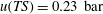 $u(TS)=0.23~\text{bar}$
. This exceeds the expanded uncertainty of the individual
$u(TS)=0.23~\text{bar}$
. This exceeds the expanded uncertainty of the individual
 $TS$
calculations. We notice that
$TS$
calculations. We notice that
 $TS<1~\text{bar}$
for all nuclei activated in the experiments, corresponding to interfacial nuclei of
$TS<1~\text{bar}$
for all nuclei activated in the experiments, corresponding to interfacial nuclei of
 $R_{n}>1~{\rm\mu}\text{m}$
, see figures 1 and 2. A tendency to a higher tensile strength at high
$R_{n}>1~{\rm\mu}\text{m}$
, see figures 1 and 2. A tendency to a higher tensile strength at high
 $P_{m}$
(high rate of tension increase) than at low
$P_{m}$
(high rate of tension increase) than at low
 $P_{m}$
(low rate of tension increase) is noticed, cf. Overton & Trevena (Reference Overton and Trevena1980, Reference Overton and Trevena1982).
$P_{m}$
(low rate of tension increase) is noticed, cf. Overton & Trevena (Reference Overton and Trevena1980, Reference Overton and Trevena1982).
In figure 9 each cavitation event is numbered, and when more than one event occurred in an experiment the first one is named A, the next B, etc. The high-frequency oscillations occurring in the system were of the order of 10 kHz, i.e. of wavelength
 ${\sim}150~\text{mm}$
, and thus the pressure changes were almost simultaneous within the
${\sim}150~\text{mm}$
, and thus the pressure changes were almost simultaneous within the
 ${\sim}10~\text{mm}\times 10~\text{mm}$
field of view. In seven experiments more than one cavity was produced in each experiment (experiments 3, 6, 7, 8, 10, 11, 12), in six experiments only one cavity was produced (experiments 2, 4, 9, 13, 14, 16), in two experiments no bottom cavitation occurred within the field of view (experiments 5, 15), in experiments 17 and 18 no cavitation activity was visible, and experiment 1 failed.
${\sim}10~\text{mm}\times 10~\text{mm}$
field of view. In seven experiments more than one cavity was produced in each experiment (experiments 3, 6, 7, 8, 10, 11, 12), in six experiments only one cavity was produced (experiments 2, 4, 9, 13, 14, 16), in two experiments no bottom cavitation occurred within the field of view (experiments 5, 15), in experiments 17 and 18 no cavitation activity was visible, and experiment 1 failed.
In three of the experiments with more than one bottom cavity the weakest nucleus was activated first, as was to be expected, but in five cases the weakest nucleus produced a cavity after a stronger one had done so. In these five cases the weak nuclei have lost tensile strength in the time that has passed since the stronger one passed critical conditions. This suggests that at tensile stressing all cavitation nuclei lose tensile strength during their growth towards critical size. This can be explained from growth of the contact radius
 $R_{n}$
beyond its initial value, when the solid–vapour–liquid contact angle (note: measured in the gas) exceeds its equilibrium value, and from diffusion of gas into the expanding nucleus over time. Therefore a nucleus, though still subcritical, may continue to grow even when a neighbouring one has passed its critical size. Thus, when a supercritical bubble grows explosively, it can be ascribed to an interfacial cavitation nucleus with a calculated contact radius
$R_{n}$
beyond its initial value, when the solid–vapour–liquid contact angle (note: measured in the gas) exceeds its equilibrium value, and from diffusion of gas into the expanding nucleus over time. Therefore a nucleus, though still subcritical, may continue to grow even when a neighbouring one has passed its critical size. Thus, when a supercritical bubble grows explosively, it can be ascribed to an interfacial cavitation nucleus with a calculated contact radius
 $R_{n}$
, but this value is the real initial size only if it has not had the time to increase during growth towards critical conditions, and if no diffusion of gas into the nucleus has occurred. In the experiments of figure 9(a) high values of tensile strength are observed primarily for high values of
$R_{n}$
, but this value is the real initial size only if it has not had the time to increase during growth towards critical conditions, and if no diffusion of gas into the nucleus has occurred. In the experiments of figure 9(a) high values of tensile strength are observed primarily for high values of
 $P_{m}$
, i.e. for fast rise of the tensile stress.
$P_{m}$
, i.e. for fast rise of the tensile stress.

Figure 10. Recorded screen positions of cavitation nuclei on the bottom leading to inception in the series of 18 experiments. (a) Overview of the observed area and (b) zoom on the area around the surface damage. The black rectangle in panel (a) indicates the zoom region. A circle (blue) indicates a nucleus at the surface damaged area and a star (red) indicates a nucleus on the smooth surface. The individual inceptions are marked with experiment number.
In figure 10 the locations of the nuclei on the bottom are shown as depicted from an angle of
 $45^{\circ }$
. Horizontal distances are elongated by the index of diffraction
$45^{\circ }$
. Horizontal distances are elongated by the index of diffraction
 $n=1.33$
, axial ones are reduced. We notice that away from the surface damage, nuclei on the painted bottom cause bubble growth only once from the same location, i.e. they are either annihilated by the cavitation process or they are left with a tensile strength higher than the experimental equipment was able to reach. On the other hand, when one nucleus had cavitated, new nuclei developed, though not necessarily already in the following experiment. This is another indication that tensile stressing made existing nuclei lose tensile strength until inception was possible. At the surface damage itself the nuclei seem relatively pinned, and inception occurs repeatedly, but at slightly varying positions, until depletion occurs.
$n=1.33$
, axial ones are reduced. We notice that away from the surface damage, nuclei on the painted bottom cause bubble growth only once from the same location, i.e. they are either annihilated by the cavitation process or they are left with a tensile strength higher than the experimental equipment was able to reach. On the other hand, when one nucleus had cavitated, new nuclei developed, though not necessarily already in the following experiment. This is another indication that tensile stressing made existing nuclei lose tensile strength until inception was possible. At the surface damage itself the nuclei seem relatively pinned, and inception occurs repeatedly, but at slightly varying positions, until depletion occurs.
6. Compression–tension pulses
Ultrasonic waves have been used for measurement of the tensile strength of liquids, assuming that the results are not influenced by symmetric oscillations of pressure (Strasberg Reference Strasberg1959; Greenspan & Tschiegg Reference Greenspan and Tschiegg1967; Herbert et al.
Reference Herbert, Balibar and Caupin2006). Therefore, in our early compression–tension (
 $CT$
-pulse) experiments (Andersen & Mørch Reference Andersen and Mørch2012) – using the equipment shown in figure 5 without the accelerometer, and with tracing of only the
$CT$
-pulse) experiments (Andersen & Mørch Reference Andersen and Mørch2012) – using the equipment shown in figure 5 without the accelerometer, and with tracing of only the
 $M$
-impact, high frequencies above 3 kHz were filtered away in the pressure recordings to focus on the basic compression pulse (
$M$
-impact, high frequencies above 3 kHz were filtered away in the pressure recordings to focus on the basic compression pulse (
 $C$
-pulse) of 1–2 ms duration.
$C$
-pulse) of 1–2 ms duration.
A high-speed video of the cavitation event generated by a
 $CT$
-pulse of
$CT$
-pulse of
 $P_{M}=4.9~\text{kg}~\text{m}~\text{s}^{-1}$
and
$P_{M}=4.9~\text{kg}~\text{m}~\text{s}^{-1}$
and
 $P_{m}=2~\text{kg}~\text{m}~\text{s}^{-1}$
is shown in figure 11(a). The time
$P_{m}=2~\text{kg}~\text{m}~\text{s}^{-1}$
is shown in figure 11(a). The time
 $t=0$
is chosen to be the moment of
$t=0$
is chosen to be the moment of
 $C$
-pulse arrival at the bottom centre shortly after
$C$
-pulse arrival at the bottom centre shortly after
 $M$
-impact on
$M$
-impact on
 $M_{block}$
. No bubble activity is observed until
$M_{block}$
. No bubble activity is observed until
 $t=1740~{\rm\mu}\text{s}$
, where a faint arc of flash reflections in the right upper half of the frame is observed, and some clear spots in the lower half. We interpret the arc to be the contour of bubble 1, which in the frame
$t=1740~{\rm\mu}\text{s}$
, where a faint arc of flash reflections in the right upper half of the frame is observed, and some clear spots in the lower half. We interpret the arc to be the contour of bubble 1, which in the frame
 $t=1900~{\rm\mu}\text{s}$
has grown to a horizontal radius of
$t=1900~{\rm\mu}\text{s}$
has grown to a horizontal radius of
 $R\approx 1.8~\text{mm}$
, the estimated bubble centre being marked with a cross. The high initial speed of the bubble wall during the exposure time of
$R\approx 1.8~\text{mm}$
, the estimated bubble centre being marked with a cross. The high initial speed of the bubble wall during the exposure time of
 $10~{\rm\mu}\text{s}$
blurs the bubble growth, but inception has probably occurred at approximately
$10~{\rm\mu}\text{s}$
blurs the bubble growth, but inception has probably occurred at approximately
 $t=1700~{\rm\mu}\text{s}$
. The bubble growth is plotted in figure 11(b). On this assumption the initial radial growth rate is approximately
$t=1700~{\rm\mu}\text{s}$
. The bubble growth is plotted in figure 11(b). On this assumption the initial radial growth rate is approximately
 $39~\text{m}~\text{s}^{-1}$
, giving a tensile strength of
$39~\text{m}~\text{s}^{-1}$
, giving a tensile strength of
 $TS_{1}\approx 23~\text{bar}$
. This calculation has a high uncertainty as the estimated growth velocity contributes quadratically, but a high tensile strength was set up. In the relaxation field of the primary cavity a number of tiny bubbles have also nucleated already at approximately
$TS_{1}\approx 23~\text{bar}$
. This calculation has a high uncertainty as the estimated growth velocity contributes quadratically, but a high tensile strength was set up. In the relaxation field of the primary cavity a number of tiny bubbles have also nucleated already at approximately
 $t=1740~{\rm\mu}\text{s}$
. They are ellipsoidal, and are located in the bulk of water, off the container bottom. Bubble 2 has a tensile strength
$t=1740~{\rm\mu}\text{s}$
. They are ellipsoidal, and are located in the bulk of water, off the container bottom. Bubble 2 has a tensile strength
 $TS_{2}<1~\text{bar}$
. These bulk water bubbles have developed from nuclei, still subcritical when the nucleus of bubble 1 passed supercritical size, but they have lost their tensile strength during the stress relaxation of the initial growth of bubble 1.
$TS_{2}<1~\text{bar}$
. These bulk water bubbles have developed from nuclei, still subcritical when the nucleus of bubble 1 passed supercritical size, but they have lost their tensile strength during the stress relaxation of the initial growth of bubble 1.

Figure 11. (a) Video of a cavitation event generated by a
 $CT$
-pulse. Here,
$CT$
-pulse. Here,
 $P_{M}\approx 4.9~\text{kg}~\text{m}~\text{s}^{-1}$
and
$P_{M}\approx 4.9~\text{kg}~\text{m}~\text{s}^{-1}$
and
 $P_{m}\approx 2~\text{kg}~\text{m}~\text{s}^{-1}$
, brass onto brass;
$P_{m}\approx 2~\text{kg}~\text{m}~\text{s}^{-1}$
, brass onto brass;
 $TS_{1}\approx 23~\text{bar}$
and
$TS_{1}\approx 23~\text{bar}$
and
 $TS_{2}<1~\text{bar}$
. The length of the horizontal scale bar is 2 mm. (b) The radius of the cavities 1 (red stars) and 2 (green squares) versus time. (c) Hydrophone recording of the
$TS_{2}<1~\text{bar}$
. The length of the horizontal scale bar is 2 mm. (b) The radius of the cavities 1 (red stars) and 2 (green squares) versus time. (c) Hydrophone recording of the
 $CT$
-pulse with HF cutoff at
$CT$
-pulse with HF cutoff at
 $3~\text{kHz}$
and with the hydrophone at
$3~\text{kHz}$
and with the hydrophone at
 $h_{p}=60~\text{mm}$
.
$h_{p}=60~\text{mm}$
.
The dramatic cavitation event in figure 11(a) is interpreted to be the result of the
 $T$
-pulse, generated by the
$T$
-pulse, generated by the
 $m$
-impact, brass onto brass, arriving at the centre of the bottom simultaneously with the tensile phase of a high-amplitude HF resonance wave of about 11 kHz (filtered away from figure 11
c), superposed on the compressive
$m$
-impact, brass onto brass, arriving at the centre of the bottom simultaneously with the tensile phase of a high-amplitude HF resonance wave of about 11 kHz (filtered away from figure 11
c), superposed on the compressive
 $M$
-impact pulse which has just come to an end. At earlier arrival of the
$M$
-impact pulse which has just come to an end. At earlier arrival of the
 $T$
-pulse it was unable to cause inception – at later arrival, inception at low tensile strength was observed. Thus, the HF waves were found to be decisive for detecting high tensile strength with the equipment.
$T$
-pulse it was unable to cause inception – at later arrival, inception at low tensile strength was observed. Thus, the HF waves were found to be decisive for detecting high tensile strength with the equipment.
Using an upper frequency limit
 ${>}$
100 kHz for the hydrophone, the
${>}$
100 kHz for the hydrophone, the
 $CT$
-pulse in figure 12(a) was obtained, here with
$CT$
-pulse in figure 12(a) was obtained, here with
 $m$
-impact on the compliant ring. The signal was recorded with the hydrophone at
$m$
-impact on the compliant ring. The signal was recorded with the hydrophone at
 $h_{p}=10~\text{mm}$
above the bottom. An improvement of the equipment had improved the bottom–cylinder contact. In the accompanying video, see supplementary data http://dx.doi.org/10.1017/jfm.2015.185, we notice that at
$h_{p}=10~\text{mm}$
above the bottom. An improvement of the equipment had improved the bottom–cylinder contact. In the accompanying video, see supplementary data http://dx.doi.org/10.1017/jfm.2015.185, we notice that at
 $t=328~{\rm\mu}\text{s}$
after the start of the flashlight, i.e. early in the
$t=328~{\rm\mu}\text{s}$
after the start of the flashlight, i.e. early in the
 $C$
-pulse, two bubbles 1 and 2 are observed, but only in a single frame, and again at the end of the
$C$
-pulse, two bubbles 1 and 2 are observed, but only in a single frame, and again at the end of the
 $C$
-pulse at
$C$
-pulse at
 $t=1048~{\rm\mu}\text{s}$
, and once more at
$t=1048~{\rm\mu}\text{s}$
, and once more at
 $t=1128~{\rm\mu}\text{s}$
, these bubbles appear – bubble 2 now as a more cloudy structure. We notice that the bubble bursts correspond to the intensive tensile phase of the 11 kHz pressure oscillations in figure 12(a), and we conclude that the compressive HF phase that follows has caused their collapse within a single frame. At
$t=1128~{\rm\mu}\text{s}$
, these bubbles appear – bubble 2 now as a more cloudy structure. We notice that the bubble bursts correspond to the intensive tensile phase of the 11 kHz pressure oscillations in figure 12(a), and we conclude that the compressive HF phase that follows has caused their collapse within a single frame. At
 $t>1000~{\rm\mu}\text{s}$
the HF-filtered pressure has dropped below the atmospheric pressure, and the bubbles 1 and 2 appear as bubble clusters that change from frame to frame until
$t>1000~{\rm\mu}\text{s}$
the HF-filtered pressure has dropped below the atmospheric pressure, and the bubbles 1 and 2 appear as bubble clusters that change from frame to frame until
 $t\approx 2200~{\rm\mu}\text{s}$
, and then they cease. However, at
$t\approx 2200~{\rm\mu}\text{s}$
, and then they cease. However, at
 $t=2928~{\rm\mu}\text{s}$
, i.e.
$t=2928~{\rm\mu}\text{s}$
, i.e.
 $10^{3}~{\rm\mu}\text{s}$
after the
$10^{3}~{\rm\mu}\text{s}$
after the
 $m$
-impact at
$m$
-impact at
 $t=1920~{\rm\mu}\text{s}$
, the bubble clusters 1 and 2 reappear, and we observe the inception of brand new bubbles, such as bubble 3 with
$t=1920~{\rm\mu}\text{s}$
, the bubble clusters 1 and 2 reappear, and we observe the inception of brand new bubbles, such as bubble 3 with
 $TS_{3}=0.1~\text{bar}$
. They grow steadily along with the bubble clusters 1 and 2, which tend to merge into single bubbles. No immediate effect of the ‘soft’
$TS_{3}=0.1~\text{bar}$
. They grow steadily along with the bubble clusters 1 and 2, which tend to merge into single bubbles. No immediate effect of the ‘soft’
 $m$
-impact is observed, but it is responsible for the growth of all bubbles at the delayed time. Bubble 3 illustrates that on exposure to tensile stress cavitation nuclei lose their tensile strength, as also the nuclei originally producing bubbles 1 and 2 have lost their tensile strength – a characteristic feature noticed already in figure 7.
$m$
-impact is observed, but it is responsible for the growth of all bubbles at the delayed time. Bubble 3 illustrates that on exposure to tensile stress cavitation nuclei lose their tensile strength, as also the nuclei originally producing bubbles 1 and 2 have lost their tensile strength – a characteristic feature noticed already in figure 7.

Figure 12. (a) Example of a
 $CT$
-pulse generated at
$CT$
-pulse generated at
 $P_{M}\approx 4.0~\text{kg}~\text{m}~\text{s}^{-1}$
and
$P_{M}\approx 4.0~\text{kg}~\text{m}~\text{s}^{-1}$
and
 $P_{m}\approx 4.4~\text{kg}~\text{m}~\text{s}^{-1}$
on a compliant ring, with the hydrophone at
$P_{m}\approx 4.4~\text{kg}~\text{m}~\text{s}^{-1}$
on a compliant ring, with the hydrophone at
 $h_{p}=10~\text{mm}$
. Hydrophone signal (top curve, red), accelerometer signal (middle curve, blue) and trigger signal: the first jump indicates flash light on and the second jump indicates
$h_{p}=10~\text{mm}$
. Hydrophone signal (top curve, red), accelerometer signal (middle curve, blue) and trigger signal: the first jump indicates flash light on and the second jump indicates
 $m$
-impact (bottom curve, black). The accelerometer signal and the trigger signal are shown in arbitrary units. (b) Excerpts from the accompanying video show single-frame cavitation at
$m$
-impact (bottom curve, black). The accelerometer signal and the trigger signal are shown in arbitrary units. (b) Excerpts from the accompanying video show single-frame cavitation at
 $t=1048~{\rm\mu}\text{s}$
after arrival of the
$t=1048~{\rm\mu}\text{s}$
after arrival of the
 $C$
-pulse at the bottom centre, and steady bubble growth with inception at
$C$
-pulse at the bottom centre, and steady bubble growth with inception at
 $t=2928~{\rm\mu}\text{s}$
due to the
$t=2928~{\rm\mu}\text{s}$
due to the
 $T$
-pulse at
$T$
-pulse at
 $t=1920~{\rm\mu}\text{s}$
, bubble 3 with
$t=1920~{\rm\mu}\text{s}$
, bubble 3 with
 $TS_{3}=0.1~\text{bar}$
. The length of the horizontal scale bar is 2 mm.
$TS_{3}=0.1~\text{bar}$
. The length of the horizontal scale bar is 2 mm.
In single-frame cavitation events inception occurs after the period of flash exposure in the preceding frame, and the bubble collapses before the exposure period of the subsequent frame, i.e. it grows and collapses within the time of two frames minus the exposure time of the first frame. The diameter of the bubble,
 $2R$
, is close to its maximum in the recorded cavitation event. Assuming parabolic growth and collapse of the bubble, a minimum value of
$2R$
, is close to its maximum in the recorded cavitation event. Assuming parabolic growth and collapse of the bubble, a minimum value of
 $TS$
for each bubble can therefore be determined from the initial growth rate
$TS$
for each bubble can therefore be determined from the initial growth rate
 $(\text{d}R/\text{d}t)|_{t=t_{i}}=4R/(2f^{-1}-{\it\tau}_{exp})$
, in which
$(\text{d}R/\text{d}t)|_{t=t_{i}}=4R/(2f^{-1}-{\it\tau}_{exp})$
, in which
 $f$
is the frame rate and
$f$
is the frame rate and
 ${\it\tau}_{exp}$
is the exposure time of each frame. The single-frame
${\it\tau}_{exp}$
is the exposure time of each frame. The single-frame
 $R$
value is a minimum value and the two-frame bubble lifetime evaluation is a maximum value. Thus, the smaller calculated values of
$R$
value is a minimum value and the two-frame bubble lifetime evaluation is a maximum value. Thus, the smaller calculated values of
 $TS$
are probably underestimated, while the large ones are realistic estimates, though with high uncertainty. For bubble 1 in figure 12(b) we calculate
$TS$
are probably underestimated, while the large ones are realistic estimates, though with high uncertainty. For bubble 1 in figure 12(b) we calculate
 $TS\geqslant 2.9~\text{bar}$
for the single-frame event at
$TS\geqslant 2.9~\text{bar}$
for the single-frame event at
 $t=328~{\rm\mu}\text{s}$
, where the pressure pulse is approximately 1.3 bar if HF-filtered, and of positive slope, and
$t=328~{\rm\mu}\text{s}$
, where the pressure pulse is approximately 1.3 bar if HF-filtered, and of positive slope, and
 $TS\geqslant 5.4~\text{bar}$
at
$TS\geqslant 5.4~\text{bar}$
at
 $t=1048~{\rm\mu}\text{s}$
and at
$t=1048~{\rm\mu}\text{s}$
and at
 $t=1128~{\rm\mu}\text{s}$
, where the basic pressure pulse has dropped to approximately
$t=1128~{\rm\mu}\text{s}$
, where the basic pressure pulse has dropped to approximately
 $0~\text{bar}$
, and the slope is negative. For
$0~\text{bar}$
, and the slope is negative. For
 $528~{\rm\mu}\text{s}<t<1008~{\rm\mu}\text{s}$
, where the maximum of the
$528~{\rm\mu}\text{s}<t<1008~{\rm\mu}\text{s}$
, where the maximum of the
 $C$
-pulse pressure was achieved, no bubbles were produced by HF pulses – they were too weak to cause inception at the highest pressures.
$C$
-pulse pressure was achieved, no bubbles were produced by HF pulses – they were too weak to cause inception at the highest pressures.
Single-frame cavitation events during the
 $C$
-pulse, as in figure 12, were regular observations, but in the few cases where they were absent, as in figure 11, the tensile strength reached particularly high values. The tensile strength values calculated from single-frame cavitation events and a few double-frame events are shown versus time after pressurization onset in figure 13. The
$C$
-pulse, as in figure 12, were regular observations, but in the few cases where they were absent, as in figure 11, the tensile strength reached particularly high values. The tensile strength values calculated from single-frame cavitation events and a few double-frame events are shown versus time after pressurization onset in figure 13. The
 $TS$
level of 1.3 bar calculated for the transition of an interfacial skin-stabilized bubble of
$TS$
level of 1.3 bar calculated for the transition of an interfacial skin-stabilized bubble of
 $R_{n}=1.6~{\rm\mu}\text{m}$
into a spherical bubble is given as a lower-limit line (blue). Single-frame cavitation events repeated themselves at the same location during an experiment, but their positions shifted from one experiment to the next. Thus, in each experiment the original nuclei were depleted when inception first occurred, but bubble remnants left weak spots in the liquid at the site.
$R_{n}=1.6~{\rm\mu}\text{m}$
into a spherical bubble is given as a lower-limit line (blue). Single-frame cavitation events repeated themselves at the same location during an experiment, but their positions shifted from one experiment to the next. Thus, in each experiment the original nuclei were depleted when inception first occurred, but bubble remnants left weak spots in the liquid at the site.

Figure 13. Tensile strength
 $TS$
versus time
$TS$
versus time
 $t$
calculated from cavitation events observed during the compression phase of
$t$
calculated from cavitation events observed during the compression phase of
 $CT$
-pulses in water. The calculations are based on single-frame or double-frame events. The tensile strength calculated for a skin-stabilized interfacial bubble of
$CT$
-pulses in water. The calculations are based on single-frame or double-frame events. The tensile strength calculated for a skin-stabilized interfacial bubble of
 $R_{n}=1.6~{\rm\mu}\text{m}$
exposed to
$R_{n}=1.6~{\rm\mu}\text{m}$
exposed to
 $p_{\infty ,C}-p_{v}=2~\text{bar}$
is inserted as a lower-limit line (blue).
$p_{\infty ,C}-p_{v}=2~\text{bar}$
is inserted as a lower-limit line (blue).
7. Discussion
The presence of interfacial cavitation nuclei on simply prepared metal surfaces was experimentally indicated already by Song et al. (Reference Song, Mørch, Carneiro and Thölén1993) by the use of scanning tunnelling microscopy (STM). Today, surface nanobubbles are the subject of intensive studies by atomic force microscopy (Seddon & Lohse Reference Seddon and Lohse2011), usually on atomically perfect specimen surfaces, but generally with limited control of interfacial contamination. The characteristic flat shape of these nanobubbles is adopted as the basis of our model. We notice a gap in size between these commonly observed nanobubbles, which are of radius less than
 $1~{\rm\mu}\text{m}$
, and the cavitation nuclei responsible for inception in plain water, being larger than
$1~{\rm\mu}\text{m}$
, and the cavitation nuclei responsible for inception in plain water, being larger than
 $1~{\rm\mu}\text{m}$
. However, the early STM investigations suggest that small gaseous voids are widely present on simple solid surfaces. Most of them are probably very small, but neighbouring ones may merge under tension (Marschall et al.
Reference Marschall, Mørch, Keller and Kjeldsen2003) – a potential field of future research.
$1~{\rm\mu}\text{m}$
. However, the early STM investigations suggest that small gaseous voids are widely present on simple solid surfaces. Most of them are probably very small, but neighbouring ones may merge under tension (Marschall et al.
Reference Marschall, Mørch, Keller and Kjeldsen2003) – a potential field of future research.
When interfacial cavitation nuclei in equilibrium with water, saturated with atmospheric air at the prevailing pressure, are exposed to tensile stress they expand. For fast pressure drop diffusion of gas into the cavitation nuclei is negligible, but if the rate of pressure drop decreases, diffusion becomes increasingly important, as is apparent from our experimental results.
In technical applications it is the tensile strength at the location where cavitation occurs, e.g. on a ship propeller, that is of interest, but usually the tensile strength is measured elsewhere. In such cases measurements should be performed so that the cavitation nuclei experience the correct pressure–time history.
The observations of depletion of cavitation nuclei after inception, and the shifting positions of nucleation for the interfacial cavities, figure 10, explain the statistical character of tensile strength measurements. Probably loss of skin molecules in the cavitation process is responsible for deactivation of a cavitation nucleus after it has suffered inception, while nuclei that have not reached critical size just retract, but with a reduced tensile strength due to gas diffusion. The depletion observed in the experiments with tensile stressing is in contrast to the bubble formation commonly observed at solid–liquid interfaces in supersaturated liquids (champagne bubbles) and at boiling, where bubbles grow slowly, but repeatedly, from the same location. Here, the skin is supposed to remain on the solid surface when the bubbles break away.
As a consequence of the above considerations, the rise time of the tensile stress pulse is important for an evaluation of the results obtained with different techniques of measurement, such as thermal straining (Berthelot Reference Berthelot1850; Harvey et al. Reference Harvey, Whiteley, McElroy, Peace and Barnes1944; Knapp Reference Knapp1958), static mechanical straining (Briggs Reference Briggs1950), ultrasonic straining (Strasberg Reference Strasberg1959; Greenspan & Tschiegg Reference Greenspan and Tschiegg1967; Herbert et al. Reference Herbert, Balibar and Caupin2006) and flow straining (Keller et al. Reference Keller, Rott, Stoffel and Striedinger1999). Moreover, when the tensile strength of water is considered in model tests for the prediction of cavitation at full scale, the scaling laws developed by Keller et al. (Reference Keller, Rott, Stoffel and Striedinger1999) are related to the pressure history that the cavitation nuclei experience on their way from the point of tensile strength measurement, usually upstream of the component being tested, to the location on the component surface where inception occurs.
While the values of the tensile strength for water (saturated with air at atmospheric pressure) were all below 1 bar when measured with
 $T$
-pulses, the HF pressure oscillations superposed on the
$T$
-pulses, the HF pressure oscillations superposed on the
 $CT$
-pulses revealed values of the tensile strength well above this level during compression, rising from the front of the compression pulse to its trailing end. However, experimentally the rise over time of pressurization was veiled by the repeated single-frame cavitation events, occurring from early in the pressurization pulse. The high values of tensile strength at pulsed pressurization were found to be of short lifetime, quickly dropping at exposure of the nuclei to tensile stressing in the tail of the pulse, figure 12.
$CT$
-pulses revealed values of the tensile strength well above this level during compression, rising from the front of the compression pulse to its trailing end. However, experimentally the rise over time of pressurization was veiled by the repeated single-frame cavitation events, occurring from early in the pressurization pulse. The high values of tensile strength at pulsed pressurization were found to be of short lifetime, quickly dropping at exposure of the nuclei to tensile stressing in the tail of the pulse, figure 12.
The model of pressurization of flat interfacial cavitation nuclei, § 2, suggests that bubbles with a tensile strength of approximately 0.5 bar are transformed into spherical nuclei of sub-micrometre size at pressurization, thereby increasing the tensile strength to above 1 bar. These small pressurized nuclei see an under-saturated water surface, and during continued pressurization at least some of the gas in the nuclei is deposited in the liquid water right at the surface of the nuclei, and they shrink. Thereby their tensile strength is increased further. However, at subsequent shift to sub-atmospheric pressure, this gas is quickly released, and the elevated tensile strength is lost. At extended exposure to tensile stress, continued diffusion of gas into the nuclei makes their tensile strength drop further, as observed in figure 12.
During long-time static pressurization, imposed at a low rate of pressure increase, the flat skin-stabilized interfacial nuclei do not shift their shape, but the gas just diffuses into the bulk of the water, and it is permanently lost from the nuclei (Harvey et al. Reference Harvey, Whiteley, McElroy, Peace and Barnes1944; Knapp Reference Knapp1958; Strasberg Reference Strasberg1959). All the skin is deposited on the solid surface, and its adhesion determines the tensile strength of the pressurized water.
The very high levels of tensile strength of water exposed to the pulse from a medical lithotripter can be explained by the leading compressive pulse collapsing the flat interfacial cavitation nuclei into very small spherical ones, driving most of their gas into solution at the bubble surfaces, thereby raising the tensile strength up to levels that prevent cavitation in the tensile tail of the pulse. However, the gas more or less reverts into the nuclei during the tensile stressing, and the high tensile strength is lost again when the tensile tail dies away. This explains observations of Borkent et al. (Reference Borkent, Dammer, Schönherr, Vancso and Lohse2007) interpreted as superstability of surface nanobubbles, and shows that a conventional medical lithotripter pulse is not suited for tensile strength measurement. However, an inverted pulse may be excellent (Mørch Reference Mørch2009), its leading tensile pulse quickly reducing the pressure below the level of inception, thereby revealing the true tensile strength of the liquid. An inverted piezo-electrical lithotripter may be focused on an object, or on bulk water, as required. It only has to be driven at amplitudes low enough to avoid cavitation on the transducer surface itself when the tensile wave is produced. Such bubbles would defocus the transducer – a problem that does not exist for ordinary medical lithotripters, in which the leading compressive pulse suppresses bubble formation on the transducer surface.
Finally, the assumption that symmetric acoustic waves do not shift the tensile strength of plain water is questionable. Usually, in experiments, the amplitude of ultrasonic pressure oscillations is raised from a low level up to the level desired, and the oscillations cause rectified diffusion of gas into the nuclei, the diffusion increasing on increase of the amplitude, i.e. a reduction of the tensile strength is imposed. We know from, e.g., Greenspan & Tschiegg (Reference Greenspan and Tschiegg1967) that at sufficiently high amplitudes of the acoustic waves, cavitation inception occurs after a period of exposure to the acoustic field, and this delay can be ascribed to rectified diffusion. Herbert et al. (Reference Herbert, Balibar and Caupin2006) reduced this effect by using pulsed HF wavepackets in studies of the upper limit of tensile strength of ultra-clean water (homogeneous nucleation). However, possible effects of the oscillating pressures on the skin-stabilized interfacial nuclei of heterogeneous cavitation, such as shape transition, are not identified at present.
The model presented assumes the skin-stabilized interfacial cavitation nuclei to be located on a planar solid surface, but appropriate modifications may extend it to surfaces of non-planar shape. For surfaces with hydrophobic crevices, Harvey et al. (Reference Harvey, Whiteley, McElroy, Peace and Barnes1944) presented the crevice model of cavitation nuclei, a model that was later improved by Atchley & Prosperetti (Reference Atchley and Prosperetti1989) and experimentally tested by Borkent et al. (Reference Borkent, Gekle, Prosperetti and Lohse2009). A merging of the crevice model with the model of skin-stabilized nuclei seems to be a tempting future research project for which some of the present experiments give a guide.
8. Conclusion
The model of skin-stabilized interfacial cavitation nuclei satisfactorily relates values of tensile strength calculated from experiments to realistic sizes of interfacial nuclei exposed to tensile stressing. The observations of weak nuclei developing to reach critical size after stronger ones have grown supercritical is explained by increase of their base radius and by diffusion of gas during their growth towards critical size. This indicates that in general all cavitation nuclei originate in stable nuclei that are smaller than the ones that can be calculated from the observable growth of supercritical bubbles. Hereby a link is established between the tensile strength of plain water and the stable nanobubble sizes commonly observed on solid–water interfaces by scanning probe microscopy.
The experiments reveal that inception causes depletion of the cavitation nuclei, which are activated on smooth surfaces; this is consistent with the model proposed. In repeated experiments new nuclei then develop at other locations.
Likewise, the model explains the observations of increased tensile strength during steep pressurization, a basic increase being achieved through the transition of the flat interfacial skin-stabilized nucleus into a more or less skin-free spherical bubble of notably smaller size. This bubble allows gas diffusion to become important, leading to further increase of the tensile strength during continued pressurization, and to loss of tensile strength during tensile stressing.
Acknowledgements
The authors wish to thank the referees for most valuable criticism, leading us to shift the paper from being primarily experimental to being based on our model of interfacial nuclei with a skin. We also thank E. Hansen for his careful work in constructing the experimental set-up.
Supplementary data
Supplementary data is available at http://dx.doi.org/10.1017/jfm.2015.185.


