


1 Introduction
The sudden expansion of supersonic flow into a duct can be seen in many engineering applications, such as in vacuum ejectors (German, Panesci & Clark Reference German, Panesci and Clark1963; Abdulateef et al. Reference Abdulateef, Sopian, Alghoul and Sulaiman2009; Lijo et al. Reference Lijo, Kim, Rajesh and Setoguchi2010), supersonic combustors (Paxson & Dougherty Reference Paxson and Dougherty2005) and hypersonic wind tunnels (Daniel Reference Daniel2010). Based on the level of expansion, the confined supersonic jet can be generally classified into two types: (1) partially expanded jet and (2) fully expanded jet. In partially expanded jets, the jet expansion is such that it does not attach to the outer duct in which the jet is confined. In fully expanded jets, the jet expansion is such that it attaches to and fully fills the outer duct in which the jet is confined. Figure 1 shows the schematic representation of these two types of jets. In certain applications, for example vacuum ejectors used in high-altitude testing facilities (HATs), it is desired that the jet be operated in fully expanded conditions (German & Bauer Reference German and Bauer1961; Annamalai et al. Reference Annamalai, Visvanathan, Sriramulu and Bhaskaran1998; Kumaran et al. Reference Kumaran, Kumaresan, Sundararajan and Manohar2009). In refrigeration systems or in vacuum pump applications, it is desired that the jet be operated in partially expanded conditions to help to enhance the pumping action (Huang, Jiang & Hu Reference Huang, Jiang and Hu1985; Chunnanond & Aphornratana Reference Chunnanond and Aphornratana2004). It is obvious that the confined jet in these systems exhibits similar shock reflections to those of an overexpanded or underexpanded open jet from a convergent–divergent (C–D) nozzle, depending on the jet pressure ratio. However, the shock systems in such confined supersonic jets will be much more complicated compared with supersonic open jets, due to the presence of the closed outer duct. One major aspect of the confined jets is that the jet induces a secondary flow which changes the pressure levels in the outer duct, and the jet pressure ratio cannot be determined easily as the jet expansion is strongly coupled to the pressure levels and vice versa (Mittal et al. Reference Mittal, Rajesh, Lijo and Kim2014). Another factor that decides the shock system in the jet is the presence of the outer duct wall. The interaction of a supersonic jet with an outer duct wall will restrict the jet expansion and distort the shock systems in the jet flow (Park, Lee & Yoon Reference Park, Lee and Yoon2008; Arun & Rajesh Reference Arun and Rajesh2016). The present work is an attempt to study the shocks prevailing in such a flow system and their reflections.

Figure 1. Schematic showing ‘partially’ (a) and ‘fully’ (b) expanded jets.
In the past, shock wave reflection has been extensively studied owing to its importance in many engineering applications involving supersonic flows. It is well understood that shock waves upon reflection from a solid wall or from a flow symmetry plane generally form two wave configurations: (1) an irregular reflection (most commonly a Mach reflection – MR) or (2) a regular reflection (RR) (Ben-Dor Reference Ben-Dor2007). The schematics representing the two wave configurations are shown in figures 2(a) and 2(b). Classical shock transformation theory (Ben-Dor Reference Ben-Dor2007) reports that a regular shock reflection occurs when the reflected shock wave (r) is capable of producing an equal flow deflection in the opposite direction to that produced by the incident shock wave (
 $\unicode[STIX]{x1D703}_{1}$
–
$\unicode[STIX]{x1D703}_{1}$
–
 $\unicode[STIX]{x1D703}_{2}=0$
in figure 2
a). On the other hand, if the reflected shock wave is not able to produce an equal deflection to that produced by the incident shock wave, a Mach reflection is formed.
$\unicode[STIX]{x1D703}_{2}=0$
in figure 2
a). On the other hand, if the reflected shock wave is not able to produce an equal deflection to that produced by the incident shock wave, a Mach reflection is formed.
For a given upstream uniform Mach number
 $M_{0}$
and a flow deflection angle by the incident shock wave
$M_{0}$
and a flow deflection angle by the incident shock wave
 $\unicode[STIX]{x1D703}_{1}$
, the possible solutions of the shock structure (MR or RR) can be generally predicted from the pressure–deflection diagrams of the incident shock (i) and the reflected shock (r), commonly known as the i-polar and r-polar respectively. From the i- and r-polars, the possible RR solution is the point where the r-polar meets the pressure axis (Ben-Dor Reference Ben-Dor2007), as shown in figure 2(a). This essentially means that the net deflection of flow after the reflected shock wave is zero, which is the necessary condition for RR. Likewise, the possible MR solution is the point where the r-polar meets with the strong part (strong-shock solution) of the i-polar (Ben-Dor Reference Ben-Dor2007) (figure 2
b).
$\unicode[STIX]{x1D703}_{1}$
, the possible solutions of the shock structure (MR or RR) can be generally predicted from the pressure–deflection diagrams of the incident shock (i) and the reflected shock (r), commonly known as the i-polar and r-polar respectively. From the i- and r-polars, the possible RR solution is the point where the r-polar meets the pressure axis (Ben-Dor Reference Ben-Dor2007), as shown in figure 2(a). This essentially means that the net deflection of flow after the reflected shock wave is zero, which is the necessary condition for RR. Likewise, the possible MR solution is the point where the r-polar meets with the strong part (strong-shock solution) of the i-polar (Ben-Dor Reference Ben-Dor2007) (figure 2
b).
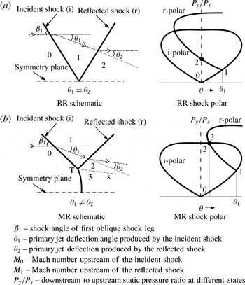
Figure 2. Schematics showing the regular reflection and Mach reflection configurations. (a) Schematic and shock polar for RR shock configuration. (b) Schematic and shock polar for MR shock configuration.
It can be seen that both RR and MR have different characteristics based on the number of discontinuities meeting at a point and the nature of the flow behind each shock wave. The transformation from one shock system to the other would bring profound changes in the flow field and is of utmost importance for aerodynamic design of supersonic and hypersonic vehicles.
The transformation from RR to MR and MR to RR in steady and pseudo-steady flows has been a subject of serious research for a long time. It is widely accepted that the two limiting criteria for the shock transformations in steady flows are the von Neumann condition (mechanical equilibrium condition) and the detachment condition (von Neumann Reference von Neumann1945; Henderson & Lozzi Reference Henderson and Lozzi1975; Hornung, Oertel & Sandeman Reference Hornung, Oertel and Sandeman1979). Above the detachment criterion, only MR structure exists, and below the mechanical equilibrium criterion, only RR structure exists. This suggests that in between these two limiting criteria, there is a possibility that either MR or RR shock structure can exist, and this region is hence called the dual-domain solution (Ben-Dor Reference Ben-Dor2007). The shock polar representations of detachment and von Neumann criteria are shown in figure 3.

Figure 3. Shock transformation criteria.
In the past, many efforts were made to predict the shock transformation and hysteresis in internal flows (Henderson & Lozzi Reference Henderson and Lozzi1975; Hornung & Kychakoff Reference Hornung and Kychakoff1977; Hornung & Robinson Reference Hornung and Robinson1982; Azevedo Reference Azevedo1989; Ivanov, Gimelshein & Beylich Reference Ivanov, Gimelshein and Beylich1995; Li, Schotz & Ben-Dor Reference Li, Schotz and Ben-Dor1996). The first experimental confirmation of the dual-domain solution was found by Chpoun et al. (Reference Chpoun, Passerel, Li and Ben-Dor1995b ). They proved the existence of both RR and MR in an internal flow over wedges by varying the wedge angles (Chpoun & Ben-Dor Reference Chpoun and Ben-Dor1995a ; Chpoun et al. Reference Chpoun, Passerel, Li and Ben-Dor1995b ). Similar works on wedge induced shock transformation and hysteresis were carried out by Sudani et al. (Reference Sudani, Sato, Noda, Karasawa, Tate and Watanabe2002) and Ivanov et al. (Reference Ivanov, Kudryavtsev, Nikiforov, Khotyanovsky and Pavlov2003). Sudani et al. (Reference Sudani, Sato, Noda, Karasawa, Tate and Watanabe2002) also showed that the effect of free-stream disturbances can initiate shock transformations in the dual domain. Ben-Dor (Reference Ben-Dor2007) gave a detailed review and bibliography of all the important works on various numerical and experimental studies on shock wave transformation and hysteresis.
Based on these studies, the main parameters that decide the shock transformations are known to be the wedge angle (Chpoun & Ben-Dor Reference Chpoun and Ben-Dor1995a ; Chpoun et al. Reference Chpoun, Passerel, Li and Ben-Dor1995b ; Ivanov et al. Reference Ivanov, Gimelshein and Beylich1995), upstream Mach number (Ivanov et al. Reference Ivanov, Ben-Dor, Elperin, Kudryavtsev and Khotyanovsky2001), upstream velocity and density perturbations (Ivanov et al. Reference Ivanov, Gimelshein, Markelov and Beylich1996; Ivanov, Gimelshein & Markelov Reference Ivanov, Gimelshein and Markelov1998; Khotyanovsky, Kudryavtsev & Ivanov Reference Khotyanovsky, Kudryavtsev and Ivanov1999) and downstream pressure (Ben-Dor et al. Reference Ben-Dor, Elperin, Li and Vasiliev1999). Apart from these, there are studies on the effects of various flow parameters on shock transformation. The effect of upstream disturbances on the RR–MR transition was studied by Li, Gao & Wu (Reference Li, Gao and Wu2011), while that of downstream waves was studied by Hu et al. (Reference Hu, Myong, Kim and Cho2009). Mouton (Reference Mouton2006) studied the effect of energy deposition in RR–MR transformation. Studies on how the transformation is affected by the presence of other waves such as shocks and expansion (Yao, Li & Wu Reference Yao, Li and Wu2013) and the dynamic effects of shock transformation (Naidoo & Skews Reference Naidoo and Skews2014) have also been carried out recently.
It is to be noted that most prior studies have examined the transformations in shock waves in internal wedge flows, which are carried out mainly in supersonic wind tunnels. Recently, there have been efforts to understand the shock transformations in open jets from supersonic nozzles operating in the overexpanded regime (Hadjadj, Kudryavtsev & Ivanov Reference Hadjadj, Kudryavtsev and Ivanov2004; Shimshi, Ben-Dor & Levy Reference Shimshi, Ben-Dor and Levy2009; Matsuo et al. Reference Matsuo, Setoguchi, Nagao, Md. Alam and Kim2011). Studies by Hadjadj and Shimshi et al. reported that in the overexpanded regime, the exit plane shock structures initially exhibit MR shock structure which then transforms to RR when the nozzle pressure ratio (NPR) increases. These studies also reported that the shock transformations in the overexpanded nozzle flow exhibit a hysteresis phenomenon with increase and decrease in NPRs.
From the literature, it can be seen that a fair understanding regarding the shock transformations in both internal flows and external flows has been acquired. The most influencing parameters are also identified as the Mach number, the geometry, disturbances in internal flows, and the pressure ratio in external flows, such as open jets. However, in many practical situations, the supersonic jets may be confined, as explained earlier in this section. There are hardly any studies that investigate the shock transformation characteristics in such confined flows, which have a profound influence on the performance of the systems (German & Bauer Reference German and Bauer1961; Annamalai et al. Reference Annamalai, Visvanathan, Sriramulu and Bhaskaran1998; Kumaran et al. Reference Kumaran, Kumaresan, Sundararajan and Manohar2009). For example, the operating pressure conditions in HATs and hypersonic test facilities are strongly coupled with the shock systems in the supersonic internal flows. Moreover, the characteristics of confined plumes containing shock waves in the HAT will decide the thrust levels of the rocket motor under testing. A detailed study of the flow characteristics in a vacuum ejector system used in an HAT can be seen in a previous work by the authors (Arun & Rajesh Reference Arun and Rajesh2016). It is hence thought to be important to study the shock characteristics in underexpanded confined jets for various total pressure and Mach number conditions.
The present paper thus aims to investigate the shock characteristics in an underexpanded jet through a confined duct. The transients in the shock structure with increasing expansion levels have been studied using time-resolved schlieren imaging and the time traces of pressure in the expanding jet. The causes for the shock transformations and the presence of hysteresis have also been investigated. For an underexpanded jet, the presence of a confined duct may alter the qualitative nature of the shock characteristics since the expansion fans from the nozzle lip deflect the flow outward, leading to the possibility of jet interaction with the outer wall.
The present paper is structured into three parts. The first part discusses the experimental techniques used in the present study. The second part comprises the results and discussion section, in which various aspects of shock transformation in both partially and fully expanded confined duct flows have been discussed. The hysteresis in shock transformation and the effect of Mach number on shock transformation are also explained in this section. The major conclusions drawn from the present experimental studies are reported at the end.
2 Experimental set-up
The experimental set-up consists of a two-dimensional straight inner duct, enclosed by a two-dimensional outer duct with a closed upstream section, as shown in figure 4(a). In the present study, a straight duct has been used to supply the jet since this chokes and produces an underexpanded jet at a low pressure ratio. The straight inner duct is supplied with high-pressure air using the blowdown facility available at the Department of Aerospace Engineering, IIT Madras, and this jet will expand into the outer duct. Various jet expansion levels required for the study are obtained by varying the jet total pressure (
 $P_{0}$
) from atmospheric conditions to the required value by controlling the blowdown valve opening process.
$P_{0}$
) from atmospheric conditions to the required value by controlling the blowdown valve opening process.
The flow transients during the jet expansion process were visualized with a time-resolved schlieren imaging technique using a conventional double-pass Z-type schlieren system. High-speed imaging was carried out using a Photron FASTCAM SA4 camera with 3600 frames per second at
 $10~\unicode[STIX]{x03BC}\text{s}$
exposure. Pressure histories in the jet-settling chamber and the outer duct were also measured. A static pressure port was also provided in the sidewall (D1 in figure 4
b) to quantify the transient jet expansion process. Pressure measurements were carried out with a Keller 21PY series transmitter (0–10 bar) with a sampling frequency of 2 kHz. The sensitivity of the sensor was
$10~\unicode[STIX]{x03BC}\text{s}$
exposure. Pressure histories in the jet-settling chamber and the outer duct were also measured. A static pressure port was also provided in the sidewall (D1 in figure 4
b) to quantify the transient jet expansion process. Pressure measurements were carried out with a Keller 21PY series transmitter (0–10 bar) with a sampling frequency of 2 kHz. The sensitivity of the sensor was
 $0.9~\text{v}~\text{bar}^{-1}$
. The pressure data acquisition and the schlieren imaging were synchronized to obtain a common starting reference time for both data acquisitions. Further details regarding the synchronization technique can be found in a previous paper by the authors (Arun & Rajesh Reference Arun and Rajesh2016). The overall experimental set-up and various pressure measurement locations are shown in figure 4(b).
$0.9~\text{v}~\text{bar}^{-1}$
. The pressure data acquisition and the schlieren imaging were synchronized to obtain a common starting reference time for both data acquisitions. Further details regarding the synchronization technique can be found in a previous paper by the authors (Arun & Rajesh Reference Arun and Rajesh2016). The overall experimental set-up and various pressure measurement locations are shown in figure 4(b).

Figure 4. The confined jet experimental set-up. (a) Test section for creating the confined underexpanded jet. (b) Schematic of the experimental set-up and sensor locations.
3 Results and discussion
This section consists of four subsections. Sections 3.1 and 3.2 discuss the shock transformation characteristics in partially and fully underexpanded confined jets with increase in the jet total pressure. Section 3.3 discusses the hysteresis phenomenon of shock transformation when the jet total pressure increases and then decreases. Section 3.4 discusses the shock transformation and hysteresis characteristics for different expansion ratios. The expansion ratio is defined as the ratio of the outer duct height (
 $D$
) to the inner duct height (
$D$
) to the inner duct height (
 $d$
), as shown in figure 4. The expansion ratio for the investigations in §§ 3.1 and 3.2 and 3.3 is 2.82, and for § 3.4 various expansion ratios have been considered. The details of the test conditions are shown in table 1.
$d$
), as shown in figure 4. The expansion ratio for the investigations in §§ 3.1 and 3.2 and 3.3 is 2.82, and for § 3.4 various expansion ratios have been considered. The details of the test conditions are shown in table 1.

Figure 5. Shock transformations with increasing
 $P_{0}$
, for a ‘partially expanded’ confined jet. (a) Schlieren image corresponding to
$P_{0}$
, for a ‘partially expanded’ confined jet. (a) Schlieren image corresponding to
 $P_{0}=3.78$
bar. (b) Schlieren image corresponding to
$P_{0}=3.78$
bar. (b) Schlieren image corresponding to
 $P_{0}=4.1$
bar. (c) Schlieren image corresponding to
$P_{0}=4.1$
bar. (c) Schlieren image corresponding to
 $P_{0}=4.27$
bar. (d) Schlieren image corresponding to
$P_{0}=4.27$
bar. (d) Schlieren image corresponding to
 $P_{0}=4.45$
bar.
$P_{0}=4.45$
bar.
Table 1. The test matrix.

3.1 Partially expanded jet
The partially expanded jet needed for the present experiment is obtained by suddenly opening the blowdown settling chamber valve (manually), so that the jet total pressure increases from atmospheric conditions to a desired total pressure which gives a partially expanded state. With the progress in the jet total pressure ramping process, the pressure ratio at the inner duct exit reaches sonic conditions, which results in a choked flow from the duct exit. Further pressure ramping up produces an underexpanded flow from the inner duct exit. Figure 5 shows the flow evolution during the initial pressure ramping up period where the jet is only partially expanded. As the set-up is two-dimensional, the flow field is contaminated by the sidewall waves. Figure 5(a) reveals that the underexpanded jet initially exhibits an RR shock structure. As the jet total pressure or the pressure ratio (jet total pressure (
 $P_{0}$
)/back pressure at inner duct exit (
$P_{0}$
)/back pressure at inner duct exit (
 $Pa$
)) increases, the RR transforms to an MR, as shown in figure 5(b). With further increase in jet total pressure, the Mach stem height increases, as shown in figure 5(c,d). Figure 5(d) also reveals that there exists a converging slipstream formed by the two slip lines emanating from the triple points in the MR shock structure. The converging slipstream indicates that the shock reflection exhibits a direct MR (Ben-Dor Reference Ben-Dor2007), and the subsonic flow after the Mach stem is accelerated inside the converging slipstream. This leads to the possibility that the jet reaches the sonic state at the end of the converging slipstreams and thereafter undergoes further expansion to reach a supersonic state. The existence of a second shock system, as seen in the schlieren image of figure 5(d), justifies the above statements.
$Pa$
)) increases, the RR transforms to an MR, as shown in figure 5(b). With further increase in jet total pressure, the Mach stem height increases, as shown in figure 5(c,d). Figure 5(d) also reveals that there exists a converging slipstream formed by the two slip lines emanating from the triple points in the MR shock structure. The converging slipstream indicates that the shock reflection exhibits a direct MR (Ben-Dor Reference Ben-Dor2007), and the subsonic flow after the Mach stem is accelerated inside the converging slipstream. This leads to the possibility that the jet reaches the sonic state at the end of the converging slipstreams and thereafter undergoes further expansion to reach a supersonic state. The existence of a second shock system, as seen in the schlieren image of figure 5(d), justifies the above statements.
The RR–MR transformation in the partially expanded confined jet is similar to an RR–MR transformation in any underexpanded open jet. This RR–MR transformation can be explicitly explained using one-dimensional gas dynamics theory and the shock polar. The increase in jet expansion level demands a higher pressure rise across the shock system. From the shock polar solution, it can be seen that a higher pressure ratio across the shock systems can be obtained from an MR solution rather than from an RR solution (figure 2). Hence, it can be argued that with increase in jet expansion level, a transformation from RR to MR takes place in the underexpanded jet in order to maintain the downstream pressure conditions. Previous experiments in underexpanded nozzle flows have clearly shown that the shock structure initially exhibits an RR which then transforms into an MR with increase in the NPR (Adamson Jr Reference Adamson1959; Gribben, Badcock & Richards Reference Gribben, Badcock and Richards2000).
In underexpanded open jets, the RR–MR transformation with increasing NPR is associated with variation in shock angles and the upstream Mach number. This is true for underexpanded confined jets also, when the jet is in a partially expanded mode, as shown in figure 8, where the shock upstream Mach number is increasing in the partially expanded mode.
3.2 Fully expanded jet
As the jet total pressure increases further, the jet expands to the outer wall, indicating the switching from the ‘partially expanded’ to the ‘fully expanded’ state (figure 6 a). Consequently, the MR shock structure in the jet stretches and attaches to the outer duct wall, denoted as point B in figure 4(a). The section where the jet expands to the outer duct is denoted as section-A and is shown in the schematic in figure 4(a). When the jet total pressure is further increased, the Mach stem of the MR shock structure is found to be moving downstream with Mach stem height reducing and eventually transforming to an RR. This is shown in figure 6(a–d).

Figure 6. Shock transformations with increasing
 $P_{0}$
, for a ‘fully expanded’ confined jet. (a) Schlieren image corresponding to
$P_{0}$
, for a ‘fully expanded’ confined jet. (a) Schlieren image corresponding to
 $P_{0}=5.07$
bar. (b) Schlieren image corresponding to
$P_{0}=5.07$
bar. (b) Schlieren image corresponding to
 $P_{0}=5.66$
bar. (c) Schlieren image corresponding to
$P_{0}=5.66$
bar. (c) Schlieren image corresponding to
 $P_{0}=5.72$
bar. (d) Schlieren image corresponding to
$P_{0}=5.72$
bar. (d) Schlieren image corresponding to
 $P_{0}=5.78$
bar.
$P_{0}=5.78$
bar.
It is hence seen that for the partially expanded confined jet, the shock transformation resembles that of an underexpanded open jet (RR to MR with increasing pressure ratio). However, when the flow is in the fully expanded state, the confined underexpanded jet exhibits a reverse transformation from MR to RR with increase in jet total pressure, which is not seen in underexpanded open jets. In fact, a shock transformation of this nature (MR to RR) with increasing pressure ratio can be seen in overexpanded open jets (Hadjadj et al. Reference Hadjadj, Kudryavtsev and Ivanov2004; Shimshi et al. Reference Shimshi, Ben-Dor and Levy2009; Matsuo et al. Reference Matsuo, Setoguchi, Nagao, Md. Alam and Kim2011).
3.2.1 Switching of underexpanded to overexpanded shock transformation mode
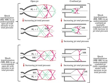
Figure 7. Schematic of shock transformation in overexpanded and underexpanded open jets with increase in NPR, and the shock transformation scenario in underexpanded confined jets with increasing pressure ratio.
One of the fundamental differences between a confined underexpanded jet and a similar open jet flow, as observed from figure 6, is that for the former, the underexpanded shock characteristics (RR–MR transformation) eventually switch to those of an overexpanded shock (MR–RR) with increase in pressure ratio, whereas for the latter, there is no such reverse transformation with increase in pressure ratio. A schematic representation of the shock transformations in underexpanded and overexpanded open jet flows with increasing pressure ratio, and the shock transformation in underexpanded confined jets with increasing pressure ratio is shown in figure 7. What follows is a detailed discussion regarding the reverse transformation of MR–RR when the pressure ratio increases in the fully expanded case.
In an underexpanded jet through a confined duct, the expansion process is restricted by the presence of the outer duct wall. Hence, in such a geometry, the maximum possible expansion can be attained when the jet expands to the outer duct wall (fully expanded state). This leads to a situation where the jet expansion at section-A (the section where the jet expands to the outer wall, see figure 4
a) reaches its maximum possible area ratio. As a result of this, the Mach number at section-A will not vary after the maximum possible jet expansion, and this is referred to as a frozen state (Arun & Rajesh Reference Arun and Rajesh2016). This can be clearly observed in figure 8, which shows the transient Mach number variation at section-A (measuring location D1 in figure 4
a) while the jet total pressure is being ramped up. The Mach number history at section-A is computed from the static pressure history at the measuring point D1 (sensor-3) and the jet total pressure history at the settling chamber (sensor-1) using the isentropic relation. Figure 9 shows the static-to-total pressure ratio and the Mach number at measuring location D1, with increase in jet total pressure. It is clearly seen from figure 9 that the static-to-total pressure ratio attains a constant value after the frozen state. This suggests that even though the absolute value of the total temperature may change over time, the flow still attains a frozen state since the total pressure to static pressure ratio achieves a constant value. Mach number calculation based on isentropic relations will be valid only after the passage of the initial shock waves in the jet to the downstream of the measuring location D1. The time duration for which the initial shock waves pass through the measuring location is marked as ‘non-isentropic’ in figure 8. Once the Mach number attains a ‘frozen’ state (fully expanded), the static pressure at section-A increases with increase in primary jet total pressure (from the isentropic
 $P/P_{0}$
relation). Figure 8 clearly depicts this trend. The increase in static pressure at section-A pushes the Mach stem of the MR, which is a normal shock wave, further downstream, as seen in figure 6(a–d). A similar kind of downstream movement of the shock with increase in the NPR can be seen in many other situations, such as those in the divergent portions of C–D nozzles and C–D diffusers.
$P/P_{0}$
relation). Figure 8 clearly depicts this trend. The increase in static pressure at section-A pushes the Mach stem of the MR, which is a normal shock wave, further downstream, as seen in figure 6(a–d). A similar kind of downstream movement of the shock with increase in the NPR can be seen in many other situations, such as those in the divergent portions of C–D nozzles and C–D diffusers.

Figure 8. Static pressure and Mach number histories at section-A (measuring location D1) with increase in jet total pressure.

Figure 9. Static-to-total pressure ratio and Mach number at section-A (measuring location D1) with increase in jet total pressure.
Schlieren flow visualization reveals that in the fully expanded state, the jet attachment point with the outer duct (point B) remains invariant even though the jet total pressure is increased, as shown in figure 10. With the onset of a frozen Mach number at section-A, the jet expansion process from the inner duct exit to section-A also freezes. This can be attributed to the reason behind the attainment of a fixed jet attachment point with the outer duct. Since the attachment point is not changing with increasing jet total pressure, the point where the incident shock wave is generated also remains unaltered. The error associated with measuring the attachment point from the schlieren image has also been calculated and is reported in figure 10. To estimate the error associated with the attachment point, two lines were constructed in the schlieren image, one along the centre of the shock wave and the other along the centre of the shear layer. These lines intersect with the top wall, and the length bounded by these two lines on the top wall was identified as the error associated with the attachment point measurement location from the schlieren image.
From oblique shock theory, it is known that the shock angle of the incident shock is fixed by the upstream Mach number and the flow deflection of the streamline required at the attachment point ‘B’ (shown in figure 11
a). For the present case, both of these parameters remain invariant due to the ‘frozen’ state at section-A, and, as a result, the incident shock angle also remains invariant after the ‘frozen’ state, even though the jet total pressure increases. The angle (
 $\unicode[STIX]{x1D719}$
) between the incident shock (i) and the outer duct top wall, and the distance between section-A and the Mach stem (
$\unicode[STIX]{x1D719}$
) between the incident shock (i) and the outer duct top wall, and the distance between section-A and the Mach stem (
 $X_{s}$
) are schematically shown in figure 11(a). These parameters have been computed from the schlieren images at various time instants and are plotted in figure 11(b). In figure 11(b), ‘
$X_{s}$
) are schematically shown in figure 11(a). These parameters have been computed from the schlieren images at various time instants and are plotted in figure 11(b). In figure 11(b), ‘
 $\unicode[STIX]{x1D719}$
’ is computed by noting the instantaneous
$\unicode[STIX]{x1D719}$
’ is computed by noting the instantaneous
 $x$
-distance of the incident shock (i) from section-A, for a fixed
$x$
-distance of the incident shock (i) from section-A, for a fixed
 $y$
-location (
$y$
-location (
 $y=24.5$
mm from the outer duct top wall). It can be observed from figure 11(b) that the angle between the incident shock (i) and the outer duct top wall remains constant after the frozen state, even when the primary jet total pressure is increasing. This implicitly confirms that after the frozen state, the shock angle ‘
$y=24.5$
mm from the outer duct top wall). It can be observed from figure 11(b) that the angle between the incident shock (i) and the outer duct top wall remains constant after the frozen state, even when the primary jet total pressure is increasing. This implicitly confirms that after the frozen state, the shock angle ‘
 $\unicode[STIX]{x1D6FD}$
’ (shock wave angle with respect to flow direction) of the incident shock also remains constant irrespective of the increase in primary jet total pressure.
$\unicode[STIX]{x1D6FD}$
’ (shock wave angle with respect to flow direction) of the incident shock also remains constant irrespective of the increase in primary jet total pressure.

Figure 10. Schlieren images showing that the shock generation point remains invariant after the fully expanded state.

Figure 11. Shock movement and shock angle variations in the fully expanded jet with increase in total pressure above the frozen state. (a) Schematic of the shock system at the onset of the fully expanded state. (b) Shock position
 $(X_{s})$
and shock angle
$(X_{s})$
and shock angle
 $(\unicode[STIX]{x1D719})$
variations with increase in jet total pressure after the completely expanded state.
$(\unicode[STIX]{x1D719})$
variations with increase in jet total pressure after the completely expanded state.

Figure 12. Schematic showing the physics of shock transformation in a fully expanded confined jet.
The measurement errors associated with shock angle measurement from schlieren imaging have also been quantified, as described below. The shock angle has been calculated from the
 $x$
- and
$x$
- and
 $y$
-coordinates of the shock location, which are obtained from the corresponding pixel values from the schlieren images. The errors associated with the identification of shock location from schlieren images can thus be related to the error in estimating the pixel values. This will be of the order of the shock thickness in the schlieren images. In order to quantify this, the average shock thickness (
$y$
-coordinates of the shock location, which are obtained from the corresponding pixel values from the schlieren images. The errors associated with the identification of shock location from schlieren images can thus be related to the error in estimating the pixel values. This will be of the order of the shock thickness in the schlieren images. In order to quantify this, the average shock thickness (
 $\unicode[STIX]{x0394}x$
) has been obtained from the instantaneous schlieren images at various time levels. In the measurements, the
$\unicode[STIX]{x0394}x$
) has been obtained from the instantaneous schlieren images at various time levels. In the measurements, the
 $y$
-coordinate has been fixed and the
$y$
-coordinate has been fixed and the
 $x$
-coordinate at the centre location of shock thickness has been measured to obtain the shock angle. The error associated with the measurement in the
$x$
-coordinate at the centre location of shock thickness has been measured to obtain the shock angle. The error associated with the measurement in the
 $x$
-coordinate will be equal to
$x$
-coordinate will be equal to
 $\pm \unicode[STIX]{x0394}x/2$
. The
$\pm \unicode[STIX]{x0394}x/2$
. The
 $x$
-coordinate error can then be used to estimate the range of shock angles possible at each time step, and its average will give the error associated with shock angle measurement. It is seen that the error in shock angle is approximately
$x$
-coordinate error can then be used to estimate the range of shock angles possible at each time step, and its average will give the error associated with shock angle measurement. It is seen that the error in shock angle is approximately
 $\pm 1.19^{\circ }$
. It should be noted that, in general, the transformation of MR with a large Mach stem to RR is associated with a significant change in shock angle. For example, an overexpanded jet with an upstream Mach number of 2.44 (the same as that in the present case) exhibits an initial MR with a shock angle of
$\pm 1.19^{\circ }$
. It should be noted that, in general, the transformation of MR with a large Mach stem to RR is associated with a significant change in shock angle. For example, an overexpanded jet with an upstream Mach number of 2.44 (the same as that in the present case) exhibits an initial MR with a shock angle of
 $64.7^{\circ }$
(shock angle corresponding to sonic angle, below which an MR with a large Mach stem appears for the first time in the overexpanded jet), which transforms to RR with a shock angle of
$64.7^{\circ }$
(shock angle corresponding to sonic angle, below which an MR with a large Mach stem appears for the first time in the overexpanded jet), which transforms to RR with a shock angle of
 $40.49^{\circ }$
at the detachment criterion. Hence, the change in the shock angle for a transformation from MR to RR is 37.4 % here. The error associated with shock angle measurement for the present case is negligible when compared with the large change in shock angles for transformation in analogous situations, and hence is not expected to have a profound influence in the present shock transformation phenomenon.
$40.49^{\circ }$
at the detachment criterion. Hence, the change in the shock angle for a transformation from MR to RR is 37.4 % here. The error associated with shock angle measurement for the present case is negligible when compared with the large change in shock angles for transformation in analogous situations, and hence is not expected to have a profound influence in the present shock transformation phenomenon.
Hence, the present study reveals that an increase in jet total pressure after the ‘frozen’ state results in an MR–RR transition with the incident shock angle (
 $\unicode[STIX]{x1D6FD}$
), the shock generation point (B) and the incident shock upstream Mach number (
$\unicode[STIX]{x1D6FD}$
), the shock generation point (B) and the incident shock upstream Mach number (
 $M$
) remaining constant. This is in contradiction to the classical shock transformations seen to date, where a shock transformation is always associated with a change in the shock wave angle, largely produced by the changes in upstream Mach number or deflection angle. In the present case, the constraint imposed by the fixed oblique shock angle results in a reduction of Mach stem height and increase in incident oblique shock leg length as the Mach stem moves downstream. The continuous reduction in Mach stem height eventually results in the transformation of MR to RR. The downstream movement of the Mach stem here is purely determined by the upstream total pressure. This proves that the shock transformation in the present situation is determined by the upstream total pressure without any variation in the shock angle or upstream Mach number. Such upstream pressure induced transformation has never been reported elsewhere. A schematic explaining this phenomenon is shown in figure 12.
$M$
) remaining constant. This is in contradiction to the classical shock transformations seen to date, where a shock transformation is always associated with a change in the shock wave angle, largely produced by the changes in upstream Mach number or deflection angle. In the present case, the constraint imposed by the fixed oblique shock angle results in a reduction of Mach stem height and increase in incident oblique shock leg length as the Mach stem moves downstream. The continuous reduction in Mach stem height eventually results in the transformation of MR to RR. The downstream movement of the Mach stem here is purely determined by the upstream total pressure. This proves that the shock transformation in the present situation is determined by the upstream total pressure without any variation in the shock angle or upstream Mach number. Such upstream pressure induced transformation has never been reported elsewhere. A schematic explaining this phenomenon is shown in figure 12.
Once the MR transforms to RR, the oblique shock wave from section-A exhibits no further movement. This can be observed from figure 11(b), which shows that neither the position of the RR shock structure (
 $X_{s}$
) nor the incident oblique shock angle varies after the shock transformation. It is hence found that the structure of the shock reflection is no longer affected by the jet total pressure, after a critical jet total pressure at which the transformation occurs.
$X_{s}$
) nor the incident oblique shock angle varies after the shock transformation. It is hence found that the structure of the shock reflection is no longer affected by the jet total pressure, after a critical jet total pressure at which the transformation occurs.
3.3 Hysteresis in shock transformation

Figure 13. Schlieren images showing the shock characteristics for increasing and decreasing jet total pressures (case 1). (a) Pressure increasing case with
 $P_{0}=3.7$
bar. (b) Pressure increasing case with
$P_{0}=3.7$
bar. (b) Pressure increasing case with
 $P_{0}=4.64$
bar. (c) Pressure increasing case with
$P_{0}=4.64$
bar. (c) Pressure increasing case with
 $P_{0}=4.94$
bar. (d) Pressure increasing case with
$P_{0}=4.94$
bar. (d) Pressure increasing case with
 $P_{0}=5.1$
bar. (e) Pressure increasing case with
$P_{0}=5.1$
bar. (e) Pressure increasing case with
 $P_{0}=5.7$
bar. (f) Pressure increasing case with
$P_{0}=5.7$
bar. (f) Pressure increasing case with
 $P_{0}=6.4$
bar. (g) Pressure decreasing case with
$P_{0}=6.4$
bar. (g) Pressure decreasing case with
 $P_{0}=5.7$
bar. (h) Pressure decreasing case with
$P_{0}=5.7$
bar. (h) Pressure decreasing case with
 $P_{0}=5.1$
bar. (i) Pressure decreasing case with
$P_{0}=5.1$
bar. (i) Pressure decreasing case with
 $P_{0}=4.94$
bar. (j) Pressure decreasing case with
$P_{0}=4.94$
bar. (j) Pressure decreasing case with
 $P_{0}=4.64$
bar. (k) Pressure decreasing case with
$P_{0}=4.64$
bar. (k) Pressure decreasing case with
 $P_{0}=3.7$
bar.
$P_{0}=3.7$
bar.
It is known that the classical shock transformation always exhibits a hysteresis phenomenon due to the dual-domain solution. It was hence decided to investigate whether a hysteresis exists in the present situation or not. The jet pressure variation is what is causing the shock transformation here, and the hysteresis is hence examined by ramping the jet pressure up and then down.
It can be observed from figure 13 that the shock structures during the pressure ramping down phase exhibit a qualitatively similar trend to that of pressure ramping up phase. The schlieren images in figure 13(a–f) represent the process in which the jet total pressure is ramped up and the images in figure 13(g–k) represent the process in which the jet total pressure is ramped down. The schlieren images for the pressure ramping down process clearly depict that the RR shock structure transforms back to MR as jet total pressure is lowered to a particular value. As the jet pressure reduces further, the MR shock structure moves upstream with the Mach stem height increasing. With further reduction in pressure, the jet eventually detaches from the outer duct wall when the jet total pressure reaches a critical value. This marks the switching of the fully expanded state back to the partially expanded state. From the schlieren images, it can be noted that the jet total pressure at which the RR–MR transformation occurs in the ramp-down phase (figure 13 h,i) is not the same as that at which MR–RR transformation happens in the ramp-up phase (figure 13 d,e). Figure 14 shows the jet (sensor-1) and the outer duct upstream (sensor-2) pressure histories when the jet total pressure increases and then decreases. From the schlieren images (figure 13 c–i) and jet pressure history (figure 14), it is found that the critical pressure for MR–RR transformation during the pressure ramp-down phase differs from that of the pressure ramp-up case. Figure 14 also reveals that the total pressure required for the complete expansion of the jet during the pressure ramp-up phase is not the same as that for the detachment of the jet from outer duct wall during the pressure reduction phase. Here, the attachment point is identified as the point where the sudden pressure reduction in the outer duct (sensor-2) ends (point S1 in figure 14), and the detachment point is identified as the point where the sudden increase in the outer duct pressure starts (point S2 in figure 14). The details regarding the identification of jet attachment and detachment points can be found in the previous work by the authors (Arun & Rajesh Reference Arun and Rajesh2016). The schlieren images in conjunction with the pressure measurement reveal a clear hysteresis in the RR–MR transformations in terms of jet total pressure. This is further made clear by estimating the Mach stem sizes during the transformation process.

Figure 14. Outer duct upstream side pressure history during the jet total pressure increase and decrease process (case 1).
Figure 15 shows the Mach stem height variation when the jet total pressure increases and decreases in the fully expanded state. Here, the Mach stem height has been calculated from schlieren images captured during the pressure increase and decrease processes. Figure 15 clearly shows that there exists a hysteresis for the shock transition.

Figure 15. Mach stem height variation when the jet total pressure is ramped up and down in the fully expanded state.

Figure 16. Total pressure required for MR–RR and RR–MR transformations for various primary jet valve opening/closing times.
In the current experiments, the opening and closing of the blowdown valve were carried out manually, and the total duration of the valve opening and closing process may vary from one experiment to another. As a result of this, the times taken for the pressure ramp up and ramp down are not the same, even though by small amounts of 1–2 s, as seen in figure 14. This leads to a possibility that the observed hysteresis phenomenon is being influenced by the blowdown valve opening/closing time or the rate of pressure change. To investigate this, experiments with various valve opening/closing times ranging from 1 to 3.5 s were carried out, and the critical total pressures required for the MR–RR and RR–MR transformations are presented in figure 16. Figure 16 clearly shows that the critical pressures are nearly the same for all of the cases for both ramp-up and ramp-down cases. This suggests that the hysteresis phenomenon in the present case is not affected by the valve opening/closing time or the rate of total pressure change. It is to be noted that this may be true only for the range of valve opening/closing times (of the order of a few seconds) considered in the present study. Highly dynamic effects, such as a rapid rate of pressure change within a few milliseconds or less, on shock hysteresis (Naidoo & Skews Reference Naidoo and Skews2014) need not be considered in this work as the operating times of the valve are quite large here.
3.4 Effect of ‘frozen’ state Mach number or expansion ratio (
 $D/d$
) on shock transformation and hysteresis
$D/d$
) on shock transformation and hysteresis


Figure 17. Schlieren images showing the shock characteristics for increasing and decreasing jet total pressures (case 3).

Figure 18. Jet total pressure and Mach number (at section-A) histories during blowdown valve opening and closing stages (case 3).
As in the case of classical wedge angle induced shock transformation, the upstream Mach number is thought to have an influence on the transformation and hysteresis in the present study also. Here, the representative upstream Mach number can be chosen as the ‘frozen’ Mach number due to two reasons. The ‘frozen’ Mach number represents the maximum expansion level of the jet, which does not vary during the transformation phase, just like the upstream Mach number being held constant in wedge induced shock transformation and hysteresis. The other reason is that the ‘frozen’ Mach number in the present experiments can be varied by varying the maximum expansion level of the jet by adjusting the ratio of outer duct area (A) to the inner duct area (A*). The A/A* can be varied by changing the outer duct height (
 $D$
) with the inner duct dimension being unchanged to keep the mass flow rate of the jet constant. For the present study, four different ‘frozen’ Mach numbers have been used, and the details of the test matrix are shown in table 1.
$D$
) with the inner duct dimension being unchanged to keep the mass flow rate of the jet constant. For the present study, four different ‘frozen’ Mach numbers have been used, and the details of the test matrix are shown in table 1.
The schlieren images depicting the shock characteristics in the jet when the jet total pressure is ramped up and then ramped down for a
 $D/d$
ratio of 1.9 (case 3 in table 1) are shown in figure 17. Figure 18 shows the jet total pressure and transient Mach number variations at section-A for case 3, during the pressure increase and decrease phases. The frozen Mach number in this case is 2.08. Figure 17 reveals that case 3 also exhibits MR–RR transformation with increase in total pressure and RR–MR transformation with decrease in jet total pressure. It is seen from figures 17 and 18 that the shock transformation also exhibits a hysteresis phenomenon. It is also observed that the critical pressures for MR–RR and RR–MR transitions reduce with reduction in frozen state Mach number.
$D/d$
ratio of 1.9 (case 3 in table 1) are shown in figure 17. Figure 18 shows the jet total pressure and transient Mach number variations at section-A for case 3, during the pressure increase and decrease phases. The frozen Mach number in this case is 2.08. Figure 17 reveals that case 3 also exhibits MR–RR transformation with increase in total pressure and RR–MR transformation with decrease in jet total pressure. It is seen from figures 17 and 18 that the shock transformation also exhibits a hysteresis phenomenon. It is also observed that the critical pressures for MR–RR and RR–MR transitions reduce with reduction in frozen state Mach number.

Figure 19. Critical jet total pressures for MR–RR and RR–MR transformation (during the blowdown valve opening and closing process respectively) for various frozen state Mach numbers.
Figure 19 shows the critical total pressures for MR–RR transformation during the pressure increase process and the critical total pressure for RR–MR transformation during the pressure decrease process for various ‘frozen’ state Mach numbers. Figure 19 clearly reveals that the critical pressures for shock transformation are not the same for jet total pressure increasing and decreasing cases and there exists a dual domain (in which both MR and RR can exist) for all of the cases considered in the present investigation. It is also observed that the range of the dual domain decreases with reduction in frozen state Mach number.
It is well known from classical shock transformation studies that the wedge angle or flow Mach number induced shock transformations in steady flows are governed by the von Neumann or detachment criterion (Ben-Dor Reference Ben-Dor2007). The von Neumann and detachment criteria are generally obtained from the shock polar solutions for various deflection angles at a constant Mach number or various Mach numbers at a constant deflection angle. The pressure equilibrium condition and the tangency of the r-polar with the pressure axis give the von Neumann and detachment conditions respectively (figure 3). However, it is seen from the present study that the von Neumann and detachment criteria obtained from shock polar solutions cannot be considered for the shock transformations in fully expanded confined jets. This is due to the fact that neither the flow Mach number nor the deflection angle changes here, and it is hence impossible to construct the shock polar solutions for the transformation. Nevertheless, an analogous situation to the present one where the shock polar solutions can be constructed is the shock transformations in overexpanded and underexpanded open jets, as explained earlier. von Neumann and detachment criteria can be obtained in terms of the NPR (NPR
 $=$
total pressure/static pressure of the jet). This is shown in figure 20, where both of the criteria have been plotted for various Mach numbers. The von Neumann transition condition is obtained by solving the equations of three-shock theory with the condition that the pressure rise produced by the reflected shock system is equal to that of a normal shock. The detachment criterion is obtained by solving two-shock theory with a condition such that the reflected shock produces the maximum possible jet deflection angle. It is seen from figure 20 that the total pressure required for transition increases exponentially with increase in Mach number.
$=$
total pressure/static pressure of the jet). This is shown in figure 20, where both of the criteria have been plotted for various Mach numbers. The von Neumann transition condition is obtained by solving the equations of three-shock theory with the condition that the pressure rise produced by the reflected shock system is equal to that of a normal shock. The detachment criterion is obtained by solving two-shock theory with a condition such that the reflected shock produces the maximum possible jet deflection angle. It is seen from figure 20 that the total pressure required for transition increases exponentially with increase in Mach number.
The MR–RR transformation occurs in the overexpanded open jet where it occurs in the underexpanded jet in the confined duct. It should be noted here that the corresponding NPR values for transformations for a particular Mach number in an open jet and a confined jet will not quantitatively match, as the former is in the overexpanded regime and the latter is in the underexpanded regime. However, the qualitative nature of the NPR variation (exponential) required for shock transformations is similar in both cases (figures 19 and 20).
The present work hence reveals interesting flow features in underexpanded confined jets. A new type of shock transformation (MR to RR), which is induced by the upstream pressure variation, can be seen in underexpanded confined jets. In this transformation, it is seen that neither the upstream Mach number nor the incident shock angle varies during the transformation. This is due to the fact that the presence of the wall fixes both the maximum area ratio to which the jet can expand and the jet deflection angle. This kind of transformation can also be expected in other applications where the flow deflections are restricted by walls, such as that in a conical nozzle with a constant-area duct at the exit, where the jet deflection angle and the shock upstream Mach number are fixed.

Figure 20. von Neumann and detachment criteria for over- and underexpanded open jets.
4 Conclusions
Experimental study on an underexpanded confined jet reveals that the shock transformation characteristics in the partially expanded mode are similar to those of an underexpanded open jet (RR to MR) with increase in jet total pressure. However, in the fully expanded mode, the confined jet shock structure exhibits a reverse transformation from MR to RR with increase in jet pressure, which is similar to MR to RR transformation with increase in pressure ratio in overexpanded open jets. It is found that the nature of the transformation with increase in jet total pressure seems to be analogous for both cases (underexpanded confined jet in fully expanded state and overexpanded open jet). However, the mechanism by which the MR transforms to RR in the two cases is found to be different, as the MR–RR transformation in a confined duct occurs without changing either the upstream Mach number or the shock angles, in contrast to the classical shock transformations. The constraint imposed by the outer wall does not allow the shock structure to change either the Mach number or the shock angles, while the Mach stem is being pushed downstream by the increasing jet total pressure, eventually transforming MR into an RR. Hence, it can be concluded that the MR–RR transformation in a confined underexpanded jet is a purely upstream pressure induced transformation which has never been studied previously.


