


Introduction
In recent years, the development of military equipment with high-performance stealth technology has increased significantly. The term “radar cross section (RCS)” represents the detectable ability of an object [Reference Xu, Wang, Chen, Zhang and Li1]. Especially in the military application, the lower RCS, the higher stealth performance. Since the antenna is an essential element of the military equipment, reducing the antenna RCS is vital to the stealth of the military equipment [Reference Jiang, Xue, Leng, Li and Ren2, Reference Genovesi, Costa and Monorchio3].
Several methods to reduce the antenna RCS have been proposed in the last decade, which can be divided into three categories according to the principle for reducing RCS.
• Reducing antenna RCS with metamaterials. There has been extensive interest in metamaterials and their applications recently. Commonly used metamaterials for antenna RCS reduction are electromagnetic band gap (EBG) [Reference Xu, Wang, Chen, Zhang and Li1], frequency selective surface (FSS) [Reference Jiang, Xue, Leng, Li and Ren2–Reference Jia, Liu, Wang, Li and Gong4], partially reflecting surface (PRS) [Reference Huang, Pan, Ma and Luo5, Reference Ren, Jiang, Zhang and Gong6], metasurface [Reference Long, Jiang and Gong7–Reference Soric, Monti, Toscano, Bilotti and Alu9], absorber [Reference Li, Gao, Cao, Zhao, Zhang and Liu10–Reference Mei, Lin, Yu, Boukarkar, Zhang and Yang12] and other metamaterials [Reference Ahmadi, Nayyeri, Soleimani and Ramahi13]. Mushroom-like EBG structures [Reference Xu, Wang, Chen, Zhang and Li1] were integrated on the patch of a conventional microstrip antenna, providing low in-band RCS. FSS is often used in combination with other elements and replaces the conventional antenna ground plane [Reference Turpin, Sieber and Werner14]. For example, PRS and FSS were used simultaneously to reduce antenna RCS in [Reference Jiang, Xue, Leng, Li and Ren2], and out-of-band antenna RCS was reduced by 12.6 dB using FSS ground plane. PRS is often used as the superstrata above the antenna [Reference Ren, Jiang, Zhang and Gong6], and a PRS layer has been used as the superstrata of a slot-coupled microstrip antenna to reduce antenna RCS in the range 8–14 GHz [Reference Huang, Pan, Ma and Luo5], with gain enhancement of approximately 7 dB. However, metamaterials operate in limited bandwidth, which hampers their application to some degree. The profile and volume of metamaterial-based antennas are also significantly increased, which is not suitable for conformal technology or portable equipment with limited space for the antenna.
• Shaping or structural-design of the antenna. For example, octagonal-shaped ultra-wideband antenna [Reference Dikmen, Cimen and Cakir15], double-sided axe-shaped ultra-wideband antenna [Reference Dikmen, Cimen and Cakir16], and Vivaldi antenna with subtraction [Reference Yu, Gong, Hong and Jiang17, Reference Rajesh, Malathi, Raju, Kumar, Prasath and Alsath18]. In order to use shaping method to reduce antenna RCS, the current distribution should be investigated at first. Then the weak distribution areas can be removed according to the current distribution. Modifications are usually distributed on the patch and ground planes simultaneously. In [Reference Dikmen, Cimen and Cakir16], five weak distribution areas were subtracted, significantly reducing the antenna RCS in the working frequency band. However, RCS reduction using this method sacrifices backward radiation and it is difficult to achieve RCS reduction for a broad angle range of the incident wave.
• The third category contains the uncommonly used methods, such as rotating antenna element [Reference Yang, Yan, Yang and Dong19], substrate integrated waveguide technology [Reference Li, Gao and Cao20], frequency selective reflector [Reference Huang, Shen and Omar21], characteristic mode method [Reference Zhao, Chen and Yang22]. In [Reference Yang, Yan, Yang and Dong19], antenna elements are distributed and rotated randomly, significantly reducing the in-band antenna RCS. However, reducing antenna RCS over a wide frequency band is a challenge for this category of modifications.
Therefore, it is imperative and important to study a new method to reduce antenna RCS across a wide frequency band and broad-angle range of incident wave with no sacrifice of radiation performances.
This paper introduces a new microstrip antenna with wideband RCS reduction. To accomplish antenna RCS reduction with radiation performance sustained, the only modification is subtracting an array of 475 square slots from the patch, and the substrate and ground plane remain unmodified. The proposed method differs from the method that reducing antenna RCS with the use of periodic structures. The geometric construction of the periodic structure must be considered when the periodic structure method is used to reduce antenna RCS, whereas the proposed method does not require geometric construction of the slots. Square slots are only used for simulation convenience, as the HFSS software finite element method was employed, which leads to a very large calculation overhead if other geometric constructions, such as polygons, circular, or irregular shapes are used.
In order to design the modified antenna, a conventional microstrip antenna should be introduced as the reference antenna at first. According to the principle of reducing antenna metal area to reduce antenna RCS, as well as the strong distributed area should be maintained to keep the radiation performance, the RCS reduced modified antenna with radiation performance maintained can be obtained. And the validity of the proposed antenna can be proved by the analysis of distribution, fabrication and measurement. Therefore, this paper is organized as follows. The section ‘Design of reference antenna’ put forward the reference antenna of this work. And the section ‘Design of modified antenna’ discusses the principle of the RCS reduction with the modified antenna proposed. A further study of distributions is carried out in the section ‘Distribution of two antennas’. And the RCS reduction for oblique incidence is compared in the section ‘RCS reduction for oblique incidence’. The prototypes of two antennas are measured and exhibited in the section ‘Fabrication and measurement’. Finally, this work is summarized in the section ‘Conclusions’.
Design of reference antenna
Firstly, a conventional microstrip antenna is designed as the reference antenna, and depicted in Fig. 1(a) with the size marked. The substrate material is FR4, with relative dielectric constant 4.4 and loss tangent 0.02. The size of substrate is 182 × 143 × 2mm3, and the patch is 90 × 60mm2. The reference antenna is fed by coaxial cables, and the feed point is 27 mm away from the origin of the coordinate system along the direction of the x-axis. The origin of the coordinate system is the same with the center of the reference antenna.

Fig. 1. Simulation results of the reference antenna. (a) Geometry of reference antenna. (b) Reflection coefficient. (c) Maximum gain. (d) Radiation patterns.
In this paper, all the simulation is carried out with the use of HFSS 13.0 software. The radiation performance of the reference antenna is demonstrated in Fig. 1. The reflection coefficient is shown in Fig. 1(b), and it can be seen that the working frequency of reference antenna is 1.19 GHz. The three dimensional of gain diagram is exhibited in Fig. 1(c), which shows that the maximum gain of the reference antenna is 3.2 dB. In addition, the radiation patterns are shown in Fig. 1(d). The monostatic RCS of the reference antenna is shown in Fig. 2. During the process of simulating scattering mode, the boundary is set to the perfectly matched layer. And the incident wave is vertical with theta polarized.

Fig. 2. The monostatic RCS of reference antenna.
The RCS result and the radiation performance of the reference antenna are proposed as a comparison with the modified antenna in the subsequent sections. Therefore, the simulated result of the reference antenna is proposed here without any analysis.
Design of modified antenna
Antenna RCS (σ) is consist of structural mode RCS (σ s) and anteσnna mode RCS (σ a), as shown in equation (1) [Reference Suh, Suk, Park, Bang and Kim23], where ϕ is the phase difference between the two mode. The structural mode RCS depends on the configuration of the antenna, and the antenna mode RCS relies on the load condition of the antenna. [Reference Liu, Fang, Wang and Xie24]
 $$\sigma {\rm =} \left \vert {\sqrt {\sigma_s} {\rm +} \sqrt {\sigma_a} e^{\,j\phi}} \right \vert ^2,$$
In this paper, RCS of the proposed antenna is reduced for the diminution of the structural mode. As the antenna RCS is related to the shape size of the antenna, the smaller size of the antenna, the lower antenna RCS. Therefore, the modified antenna RCS would be reduced through the reducing metal area on the patch plane. As the metal area on the patch plane reduced, the scattering caused by the patch would be reduced. Whereas, the radiation performance is closely related to the size of the antenna, especially the working frequency of the antenna. In this paper, in order to realize reducing the area of the patch with radiation performance maintained, many square slots are subtracted from the edge of the patch. So the working principle of the modified antenna in the radiating mode is the same with that of the reference antenna. As the reference antenna and modified antenna was designed working within the L-band, and the length of each slot must be far less than the wavelength of the working frequency for keeping the radiation performance maintained, so each slot would be set to be a square with 1 mm length. Since the vacancy introduced by the subtracted slots, the antenna RCS can be reduced with the radiation performance maintained. In this paper, the modification processed on the patch plane only, for the sake of sustaining the backward-radiation characteristics of the reference antenna.
The influence of slots amount on the antenna radiation performance and RCS reduction is analyzed firstly. The four compared antennas are shown in Figs. 3(a) –3(d), and each of them are subtracted for 33 slots, 57 slots, 79 slots, 103 slots, respectively. The dark part on the patch in Fig. 3 represents for the subtracted slots. The compared return loss result is depicted in Fig. 4(a), and the RCS result is compared in Fig. 4(b). It can be seen that the working frequencies and the matching condition of different antennas are almost the same, which infers that the subtracted slots almost have no effect on the antenna radiation performance. In Fig. 4(b), it shows that the antenna with 103 slots exhibits best RCS reduction in the L-band, and the maximum RCS reduction is obtained by this antenna either. It can be inferred that the more area subtracted on the patch, the more RCS reduced.

Fig. 3. Geometry of four compared antenna. (a) 33 slots antenna. (b) 57 slots antenna. (c) 79 slots antenna. (d) 103 slots antenna.

Fig. 4. Simulation results of the compared antenna. (a) Return loss. (b) Monostatic RCS.
Secondly, the array of slot is proposed to have more slots subtracted from the patch. The array with different row of slots is analyzed and compared for their return loss and RCS reduction. The antenna with 103 slots in Fig. 3(d) is the fundamental antenna, termed as antenna 1. The antenna 2 consists of two rows of slots, as shown in Fig. 5(a). According to this subtracting regular, antenna 3, antenna 4, antenna 5, antenna 6, antenna 7, and antenna 8 can be proposed, respectively. And only antenna 2, antenna 3, antenna 5, and antenna 8 is demonstrated in Figs. 5(a)–5(d). The return loss and RCS of eight antennas with different slots are compared and shown in Fig. 6. It can be seen that the working frequencies have a slight change. As to the antenna RCS reduction, it can be obtained that the RCS curves of antenna 6, antenna 7, and antenna 8 are almost coincided. As a result, the maximum RCS reduction is obtained by antenna 5, and the maximum in-band RCS reduction is obtained by this antenna either. The RCS reduction performance of antenna 6, antenna 7, and antenna 8 is inferior to that of antenna 5. It is attributed to the modified length on the patch of three antennas is approximating to the wave length, which has no effect on the antenna RCS reduction in the low-frequency band.

Fig. 5. Geometry of four compared antenna. (a) antenna 2 with two-row slots. (b) antenna 3 with three-row slots. (c) antenna 5 with five-row slots. (d) antenna 8 with eight-row slots.

Fig. 6. Simulation results of the compared antenna. (a) Return loss from antenna 1–5. (b) Return loss from antenna 5–8. (c) Monostatic RCS from antenna 1–5. (d) Monostatic RCS from antenna 5–8.
According to the analysis above, the modified antenna can be proposed. In order to keep the radiation directivity, especially the back-forward radiated, there is no modification introduced on the ground plane of the antenna. The modified antenna is shown in Fig. 7(a), and it has consistent dimension to the reference antenna. The only modification is the subtraction of the 475 square slots on the patch, shown as dark points in Fig. 7(a). A 5 × 45 unit array is dug from the top of the patch, and two 30 × 5 unit arrays are dug from the left and right side of the patch. Part of the modification is shown in Fig. 7(b), and the square slots presented as blank slots in Fig. 7(b). The square slots are 1 × 1mm2, and the distance between adjacent slot is 1 mm, either along the X or Y-axis. The distance from the edge of the slot to the edge of the patch is 0.5 mm. There are no further modifications to the reference antenna other than these square slots on the patch.

Fig. 7. (a) Geometry of modified antenna. (b) A part of modification on the patch plane.
It is worth noting that the length of each slot should be far less than the wavelength of the working frequency to maintain the radiation performance of the antenna. In addition, the antenna RCS reduction is obtained through subtracting the slots near the edge of the patch in this paper. It is different from the traditional shaping method for subtracting the weak distribution area of the patch or ground plane [Reference Dikmen, Cimen and Cakir16, Reference Rajesh, Malathi, Raju, Kumar, Prasath and Alsath18]. Because the subtracted slots in this paper distributed both in the strong distribution area and the weak distribution area. If according to the traditional shaping method, the subtracted slots should distributed in the top and the bottom of the patch, whereas the subtracted slots in this paper distributed along the edge of the patch actually.
The radiation performance of the modified antenna is demonstrated in Figs. 8 and 9. Each performance of the modified antenna is compared with that of the reference antenna. Figure 8(a) shows that the working frequency of the modified antenna is 1.19 GHz, as well as the working frequency of the reference antenna is 1.19 GHz. The curves of the reflection coefficient for two antenna almost coincide. In Fig. 8(b), it shows that the maximum gain of the modified antenna is 3.3 dB, which is 0.1 dB bigger than that of the reference antenna shown in Fig. 1(c). The radiation patterns of the modified antenna are demonstrated in Figs. 9(a) and 9(b). It can be seen that the gain of backlobe increased slightly, it is due to the subtracted slots along the edges of the patch. Generally, the radiation performance of the reference antenna is maintained with the modification in this paper. So the modification of subtracted slots has no effect on the radiation performance of the antenna.

Fig. 8. (a)The reflection coefficient of the modified antenna. (b) Maximum gain.

Fig. 9. The comparison of radiation patterns between two antennas. (a) E-plane. (b) H-plane.
Figure 10 shows the monostatic RCS of the reference and modified antennas with the incident wave normally impinging and θ polarized. It can be obtained that the modified antenna achieved a significant RCS reduction of 7.6 dB at 1.19 GHz. In the frequency band 1.1–2.6 GHz, approximately 3 dB RCS reduction was achieved. Since the working frequency is 1.19 GHz, the relative bandwidth of the RCS reduction is approximately 126%. The maximum RCS reduction was 7.6 dB at 1.19 GHz, which was also the maximum in-band RCS reduction. The maximum out-of-band RCS reduction is 3.7 dB, and it occurred at the frequency of 1.9 GHz. As the working frequency range of the modified antenna is 1.14–1.21 GHz, so the in-band and out-of-band antenna RCS reduction can be obtained simultaneously through the subtracting the slots near the patch.

Fig. 10. The monostatic RCS of modified and reference antennas.
Distribution of two antennas
Firstly, in order to compare the radiation performance and scattered performance of two antennas, the distributions in both radiating mode and scattering mode of the reference antenna are studied. In the radiating mode, the distribution of the surface current at the frequency of 1.19 GHz is demonstrated in Fig. 11(a). It shows that the most of the surface current spread from the bottom of the patch to the top, and the current with large intensity located in the middle of the patch, and the weak current located along the edge. The distribution of the electric field at the frequency of 1.19 GHz is shown in Fig. 11(b). It can be seen that the electric field at the top and bottom of the patch are stronger than that in the middle of the patch.
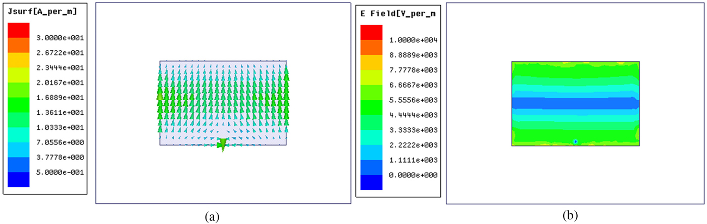
Fig. 11. Distribution of reference antenna in the radiating mode at the frequency of 1.19 GHz. (a) Surface current distribution. (b) Electric field distribution.
In the scattering mode, the distribution of the surface current at the frequency of 1.19 GHz is exhibited in Fig. 12(a). The surface current spread from the bottom of the patch to the top, the direction is almost the same with the surface current in the radiating mode. Whereas the amplitude of the two cases is different. Besides, the intensity of the surface current in the scattering mode is asymmetric. The amplitude distribution of the electric field is shown in Fig. 12(b). It shows that the stronger electric field located near the corners of the patch, and the distribution of the electric field is asymmetric either.

Fig. 12. Distribution of reference antenna in the scattering mode at the frequency of 1.19 GHz. (a) Surface current distribution. (b) Electric field distribution.
As a comparison, the distribution of the modified antenna in the radiating mode and scattering mode is analyzed, as shown in Figs. 13 and 14, respectively. The distribution of surface current in the radiating mode at the working frequency is demonstrated in Fig. 13(a). The amplitude in Fig. 13(a) is the same as that in Fig. 11(a). It can be seen that the two distributions are almost the same, except the current in the edge of the modified antenna is stronger than that of the reference antenna. And the distribution of electric field in Fig. 13(b) is similar to the distribution in Fig. 11(b). Therefore, it can be obtained that the two antennas show the similar radiation performance.

Fig. 13. Distribution of modified antenna in the radiating mode at the frequency of 1.19 GHz. (a) Surface current distribution. (b) Electric field distribution.

Fig. 14. Distribution of modified antenna in the scattering mode at the frequency of 1.19 GHz. (a) Surface current distribution. (b) Electric field distribution.
In the scattering mode, the distribution of surface current is shown in Figs. 14(a) and 14(b) for the distribution of electric field. It can be seen that the direction in Fig. 14(a) is the same as that in Fig. 12(a). According to the different amplitudes of two figures, it is easy to be obtained that the intensity of the surface current on the modified antenna is stronger than the current on the reference antenna. As for the case of the electric field, it can be obtained that the intensity of electric field on the modified antenna is stronger than the electric field on the reference antenna by comparing Fig. 14(b) with Fig. 12(b).
Comparing the radiation field distribution of the modified antenna with that of the reference antenna, it can be seen that the radiation field distribution of the two antennas almost the same. So it can prove that the radiation performance is maintained by the modified antenna. As for the scattering field distribution, the direction of scattering current of two antennas is the same, whereas the intensity is different. The current of the modified antenna is stronger than the current of the reference antenna. This is also suitable for the regulation between the scattering electric field distribution. It can be obtained that the scattering electric field of the modified antenna is stronger than that of the reference antenna. The difference between the scattering field of two antennas caused by the decrease of the metal area on the patch plane.
RCS Reduction for oblique incidence
The antenna RCS reduction in different incident angles is discussed in this section. The electromagnetic wave is vertical incidence with theta polarized. And theφis fixed to 0, the θ varies from 0° to 75° with a step for 15°. The RCS curves of different angles are depicted in Figs. 15(a)–15(f), which represent for θ = 0°,θ = 15°, θ = 30°,θ = 45°, θ = 60°, θ = 75°, respectively.

Fig. 15. The RCS result of oblique incidence. (a) θ = 0°, (b) θ = 15°, (c) θ = 30°, (d) θ = 45°, (e) θ = 60°, (f) θ = 75°.
In Fig. 15, it can be seen that the antenna in-band RCS can be dramatically reduced in all the cases. Thanks to the symmetry of the modification on the patch, the in-band RCS reduction can be obtained within the scope of 0° ≤ θ ≤ 75°. Whereas the out-of-band RCS reduction cannot be obtained in all the cases. For instance, in the case of θ = 15°, the out-of-band RCS of the modified antenna at a frequency of 2 GHz is increased than that of reference antenna.
Therefore, the modified antenna proposed in this paper can realize wideband and RCS reduction with radiation performance maintained, as well as the broad-angle in-band antenna RCS reduction.
Fabrication and measurement
Prototypes of the reference and modified antenna are fabricated, as shown in Fig. 16. The rule is placed next to the prototypes for scale. An SMA connector is welded to each prototype. The prototype reflection coefficient is measured using Agilent E8363B vector network analyzer, with the prototype and vector network analyzer connected by the feed line. The experiment arrangement is shown in Fig. 17(a), and the measured result is shown in Fig. 17(b). The measured results of the two antennas coincident and the simulated results for the two antennas are almost coincident. The bandwidth of the two antennas and impedance matching are also the same. Thus, the modifications have no significant influence on the reflection coefficient of the reference antenna.

Fig. 16. The pictures of prototypes. (a) Top view of reference antenna. (b) Top view of modified antenna. (c) Bottom view of reference antenna. (d) Bottom view of modified antenna.

Fig. 17. (a) The experimental setup of reflection coefficient. (b) Measured result.
Radiation patterns of the two prototypes are measured in a microwave anechoic chamber, with the fabricated antennas connected to an Anritsu MS4644A vector network analyzer by the feed line. The experimental setup for radiation pattern measurement is shown in Fig. 18(a). The prototype is placed on the workbench of the microwave anechoic chamber, using plastic foam to fix the prototype, since the dielectric constant of the plastic foam is similar to air. The measurement frequency is chosen as 1.19 GHz, which is the resonant frequency of the fabricated antenna. The measured results are compared in Figs. 18(b) and 18(c), for the E-plane and H-plane, respectively. The two antennas exhibit the same radiating direction and almost the same back lobe. Thus, the modification almost has no influence on the radiation patterns.

Fig. 18. (a) The experimental setup of radiation patterns. (b) Measured radiation pattern for E-plane. (c) H-plane.
Differences between the measured and simulated results are attributed to the welding and feed line, as the differences are mainly evident in the back lobe. Despite the measured result being distinguishable from the simulated result in terms of accurate values, the analytical expression from the measured result agrees well with that from the simulation.
The monostatic RCS of the two antenna prototypes are measured in the microwave anechoic chamber and the result is compared in Fig. 19. The incident wave is a vertical incident with Theta polarized. The measured result shows that the monostatic RCS of the modified antenna is lower than that of the reference antenna. The difference between the measured result and the simulated result is caused by the idealized condition of the simulation and the machining error while fabricating.

Fig. 19. The measured monostatic RCS of modified and reference antennas.
Although the RCS reduction of measured result is not as obvious as that of the simulated result, the conclusion can be drawn that the modified antenna can reduce the antenna in-band and out-of-band RCS simultaneously with the radiation performance maintained.
Conclusions
This paper proposes a novel microstrip antenna which achieves in-band and out-of-band RCS reduction simultaneously, and the antenna RCS reduction can be achieved in the case of oblique incidence. The RCS reduction performance of the novel antenna in this paper is compared with the antennas in the references, as shown in Table 1. It can be obtained that the advantages of the modified antenna are simplicity, in-band and out-of-band RCS reduction simultaneously, and serviceable for oblique incidence. The prototypes of the proposed antenna and reference antenna are fabricated and measured, and the simulated result is proved by the measured result. Therefore, this study is meaningful and useful for antenna RCS reduction technology.
Table 1. RCS reduction comparison of the proposed antenna and the antennas in references

 Zhang JiaKai was born in Shannxi Province, China, in 1990. He received the M. Sc. and B.Sc. degree in School of Electronics and Information, Northwestern Polytechnical University in Xi'an city, China, in 2012 and 2015, respectively. He is presently working on his doctoral degree in School of Electronics and Information, Northwestern Polytechnical University in Xi'an city, China. His research interests include Electromagnetic Metamaterials and antenna RCS reduction study. E-mail: zjkyikun@mail.nwpu.edu.cn
 Qi Zheng was born in Anhui, China, in 1993.He received a B.S. in Mathematics and Applied Mathematics from the School of science, Northwestern Polytechnical University, 2014. Then, he obtained an M.S. in Electronic and Information Engineering from the School of Electronic and Information, Northwestern Polytechnical University, 2016. Now, he is currently pursuing the Ph.D. degree in Electronic Science and Technology from the school of Electronic and Information, Northwestern Polytechnical University. His research interests include design of reflectarray, metamaterials, RCS reduction.
 Haixiong Li was born in Shannxi Province, China, in 1982. IEEE Student Member, CIE Student Member. He received the B.Sc. degree in School of Electrical Information Science & Engineering, Lanzhou University in Lanzhou city, China, in 2006. He received the M.Sc. degree in School of Information Science and Technology, Xiamen University in Xiamen city, China in 2013. He is presently working on his doctoral degree in School of Electronics and Information, Northwestern Polytechnical University in Xi'an city, China. His research interests include Electromagnetic Metamaterials and MIMO antenna design. E-mail: lihaixiong_02@163.com
 Jun Ding was born in Shannxi Province, China, in 1964. She received the M.Sc., B.Sc., and Ph.D. in School of Electronics and Information, Northwestern Polytechnical University in Xi'an city, China, in 1986, 1989, and 2005, respectively. She is a professor in School of Electronics and Information NWPU. She has published more than 100 research papers. Her research interests include; Electromagnetic Metamaterials, the antenna theory and design, and the microwave circuit design. E-mail: dingjun@nwpu.edu.cn
 Chenjiang Guo was born in Shannxi Province, China, in 1963. CIE Senior Member, Antenna Society Committee Member. He received the M.Sc., B.Sc., and Ph.D., in School of Electronics and Information, Northwestern Polytechnical University in Xi'an city, China, in 1984, 1987, and 2007, respectively. He is a professor in School of Electronics and Information NWPU. He has published more than 140 research papers. His research interests include; EMI/EMC, the antenna theory and design, and the microwave circuit design. E-mail: cjguo@nwpu.edu.cn


