Introduction
The power divider is one of the key passive components in power combining amplifiers and antenna arrays. Traditional Wilkinson power divider is widely used in microwave and millimeter-wave systems because of its simple structure, easy to design, and good isolation. However, the heat dissipation of the isolation resistor is a major issue for high-power applications because the isolation resistor is not grounded. It is well known that the Gysel power dividers [Reference Guan, Zhang, Sun, Leng and Peng1–Reference Abbosh and Henin11] have the high power-handling capability by introducing two short-circuited resistors that can transfer the heat to the ground plane effectively. In the past decades, more attention have been focused on the Gysel power dividers with different functions, such as multi-band [Reference Park2–Reference Hayati, Malakooti and Abdipour5], wideband [Reference Oraizi and Sharifi6, Reference Hu, Song and Fan7], bandpass filtering response [Reference Wu, Guo and Mao8, Reference Wu, Jiao and Wang9], and arbitrary power division ratio [Reference Oraizi and Sharifi10].
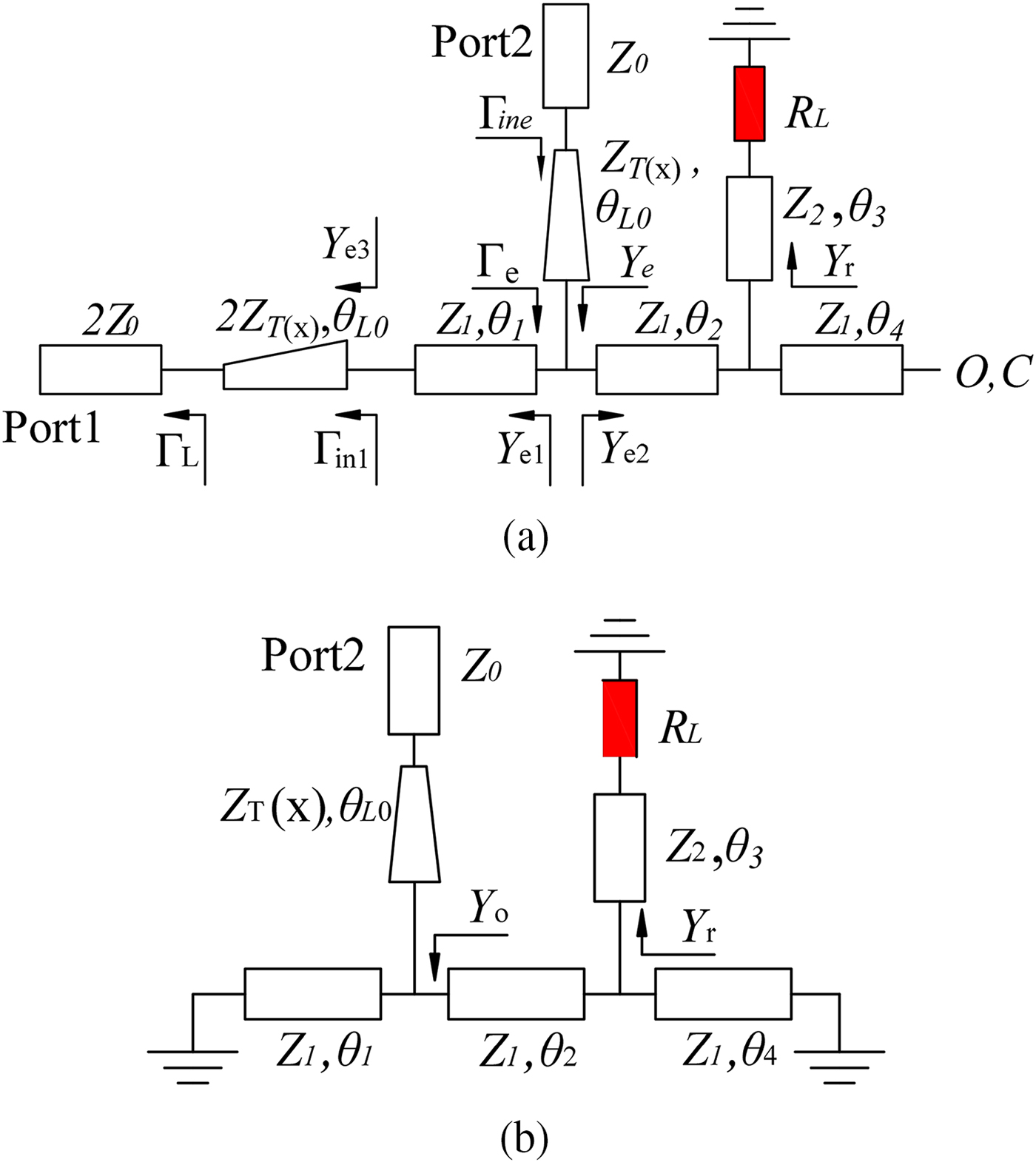
On the other hand, the high heat will generate in the transmission lines of the traditional Gysel power dividers (see Fig. 1(a)) under the condition of high input power, which cannot be removed rapidly and effectively because of the small radiating area of the microstrip transmission lines and the lack of effective heat sinking. Then, the thin microstrip transmission lines (in general the thin copper is used) will be seriously oxygenated and burned down by the high heat.

Fig. 1. (a) Conventional and (b) presented Gysel power divider.
The substrate integrated waveguides (SIWs) are developed as an attractive technique for low loss, low cost, high power-handling capability, and high-density integration. Half mode SIW (HMSIW) is a type of miniaturized SIW [Reference Lai, Fumeaux, Hong and Vahldieck12]. Several SIW and HMSIW power dividers have been studied in [Reference Song and Fan13–Reference Moznebi and Afrooz18] and some good performances such as low loss, high power-handling capability, and easy integration are reported.
In this paper, a novel wideband Gysel HMSIW power divider with high power-handling capability has been developed. The presented circuit is achieved based on a HMSIW ring, while two grounded isolation resistors are used to realize good isolation between output ports. Moreover, its good performance has been demonstrated experimentally of compact size, high isolation, and good input/output impedance matching.
Design and analysis of the proposed power divider
Figure 1(b) shows the presented Gysel HMSIW power divider. It consists of a HMSIW ring, three HMSIW-microstrip gradual taper transitions, and two microstrip stubs to assemble two isolation resistors. It is obvious that the heat of the transmission lines can be radiated to the atmosphere rapidly and effectively because of the large radiating area, and removed to the ground plane (heat sinking) through the via holes. Then, compared with the traditional microstrip Gysel power dividers, the relative low temperature of the presented HMSIW Gysel power dividers can be kept under the condition of high input power (such as more than 100 W).
Good impedance matching can be implemented by using the HMSIW–microstrip taper transitions. The length between the input port and the output port are chosen to λg/4 (λg is the guided wavelength of HMSIW at the center frequency), while the HMSIW ring's length between two isolation resistors is λg/2. Moreover, the length of the two microstrip stubs L1 is also chosen to be λg/4 to achieve the impedance matching between the HMSIW ring and the isolation resistors. The even- and odd-mode analysis method can be applied to analyze and design the presented Gysel HMSIW power divider due to the circuit symmetry. If two signals of same amplitude and in phase (even mode) are applied at two output port, by symmetry a voltage maximum occurs at every point on the line of symmetry. That is, at these points Z = ∞. This is the equivalent of an open circuit as illustrated in Fig. 2(a) and the O, C represent open circuit. Similarly, if two signals of same amplitude and out of phase (odd mode) are applied at two output port, a voltage minimum occurs at every point on the line symmetry. That is, at these point Z = 0. This is the equivalent of a short circuit as illustrated in Fig. 2(b) and the short circuit is grounded.

Fig. 2. Even- and odd-mode equivalent circuit of the presented power divider: (a) even mode, (b) odd mode.
The even and odd mode analysis can simplify the circuit. With even mode excitation and odd mode excitation, the simplified circuit can be analyzed, respectively. Figure 2(a) shows the even-mode circuit model for a bisection of this power divider. Firstly, it gives the impedance/admittance analysis of the parts of the even mode circuit. The input impedance is Z 0, as for a bisection of input post, the input impedance is 2Z 0. It is the same as micro taper which is 2Z T(x) in the even mode circuit. The characteristic impedance Z T(x) of the microstrip taper can be given by
 $${\rm Z}_T(x) = \displaystyle{{120\pi /\sqrt {\varepsilon _e}} \over {w(x)/d + 1.393 + 0.667\ln [w(x)/d + 1.444]}},$$
where w(x) = [x(w 1 − w 0) + w 0L 0]/L 0 and x is the position along the taper. So the reflection coefficient and the input admittance of the gradual taper at x = L 0 is given by
 $$\Gamma _{{\rm in}1} = \displaystyle{1 \over 2}\int_0^{{\rm L}_0} {e^{ - j2\beta {\rm x}}\displaystyle{{d[\ln 2Z_T({\rm x})]} \over {d{\rm x}}}} d{\rm x} + \Gamma _L,$$
 $$Y_{e3} = \displaystyle{{1 - \Gamma _{{\rm in}1}} \over {(1 + \Gamma _{{\rm in1}})2Z_T(L_0)}}.$$
The total input admittance Y e can be expressed as
 $$Y_e = Y_{e1} + Y_{e2},$$
where
 $$Y_{e{\rm 1}} = Y_1\left( {Y_{e3} + jY_1\tan \theta _1} \right)/\left( {Y_1 + jY_{e3}\tan \theta _1} \right),$$
 $$Y_{e{\rm 2}} = Y_1\displaystyle{{Y_r + jY_1(\tan \theta _2 + \tan \theta _4)} \over {Y_1 + j(Y_r + jY_1\tan \theta _4)\tan \theta _2}},$$
where Y 1 is the characteristic admittance of HMSIW and
 $$Y_r = \displaystyle{{Z_2 + jR_L\tan \theta _3} \over {Z_2(R_L + jZ_2\tan \theta _3)}}.$$
Moreover, the reflection coefficient Γe can be given by
 $$\Gamma _e = \left( {1 - Y_eZ_T(w_1)} \right)/\left( {1 + Y_eZ_T(w_1)} \right).$$
The input reflection coefficient Γine at port 2 can be given by
 $$\Gamma _{{\rm in}e} = \displaystyle{1 \over 2}\int_0^{L_0} {e^{ - j2\beta {\rm x}}\displaystyle{{d[\ln Z_T({\rm x})]} \over {d{\rm x}}}} d{\rm x} + \Gamma _e,$$
with the help of the formulas above, the desired input reflection coefficient of the presented power divider can be analyzed and synthesized. For example, according to (9) and the circuit sizes can be determined under the desired circuit design parameters (such as central frequency, bandwidth, return loss, etc.).
Under the odd-mode excitation, a bisection of the power divider is shown in Fig. 2(b). The input admittance Yo can also be expressed by
 $$Y_o = Y_1\displaystyle{{Y_r + jY_1(\tan \theta _2 - \cot \theta _4)} \over {Y_1 + j(Y_r - jY_1\cot \theta _4)\tan \theta _2}} - Y_1\cot \theta _1.$$
When θ 1 = θ 2 = θ 4 = π/2,Y e = Y o = 1/Z T(w 1), good impedance matching can be achieved, and (4) and (10) can be reduced as
 $$Z_1 = \sqrt 2 Z_T(w1),$$
 $$R_L = Z_2^2 /Z,$$
where Z 1 is the characteristic impedance of HMSIW. Equations (11) and (12) provide a simple guideline in the selection of Z1 and RL.
The even and odd mode analysis gives rough design parameters of the power divider. Furthermore, the power divider needed to optimize by commercial simulation software accurately.
Experimental results
Based on the design procedure discussed above, a Gysel HMSIW power divider has been designed. The Taconic RF-35 substrate with a relative dielectric constant of 3.5, the thickness of 0.508 mm, loss tangent of 0.0018 is used. The commercial software HFSS is used for optimizing the proposed power divider. The photograph of the fabricated power divider is shown in Fig. 3. The final sizes of this circuit are (unit: mm): L 0 = 8.5, L 1 = 6, L 2 = 11, L 3 = 19.5, L 4 = 5.85, s = 0.9, d = 0.5, W 0 = 1.11, W 1 = 4.5, W 2 = 1.6, W 3 = 12.4, W 4 = 17.2, R L = 70 Ω.

Fig. 3. Photograph of the fabricated power divider.
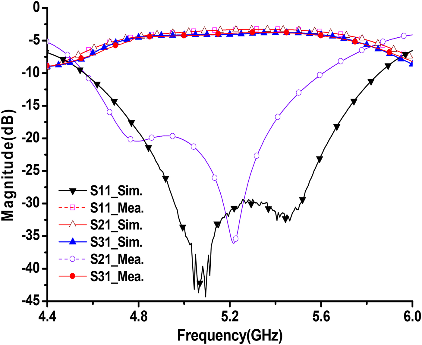
Figure 4 shows the measured and simulated input return loss and insertion loss of the fabricated HMSIW power divider. The simulated input return loss is greater than 15 dB from 4.65 to 5.45 GHz, while the measured one is greater than 15 dB from 4.7 to 5.7 GHz and greater than 25 dB in the frequency range of 4.9–5.56 GHz. The simulated 1-dB insertion loss bandwidth (the 3 dB power division loss is not included) is about 900 MHz (4.8–5.7 GHz), while the measured one is about 850 MHz (4.8–5.65 GHz). The measured minimum insertion loss is about 0.7 dB. Compared with the simulation results, the increased insertion loss is most likely attributed to the fabrication error and the loss of the SMA connectors, which are not included in the simulation model.

Fig. 4. Simulated and measured input return loss and insertion loss.
Figure 5(a) shows the simulated and measured output return losses. It can be seen that the simulated output return loss is greater than 14 dB from 4.65 to 5.5 GHz, while the measured one is greater than 15 dB from 4.8 to 5.65 GHz. Moreover, the measured isolation is greater than 15 dB in the frequency range of 4.95–5.75 GHz, as shown in Fig. 5(b). It can be seen that a measured maximum amplitude imbalance of ± 0.2 dB and a phase imbalance of ± 2° are observed from 4.6 to 5.8 GHz. Table 1. shows the comparison with other HMSIW power dividers in recent years. It demonstrates that this work has realized the better performance of isolation, input/output return loss, and compact size.
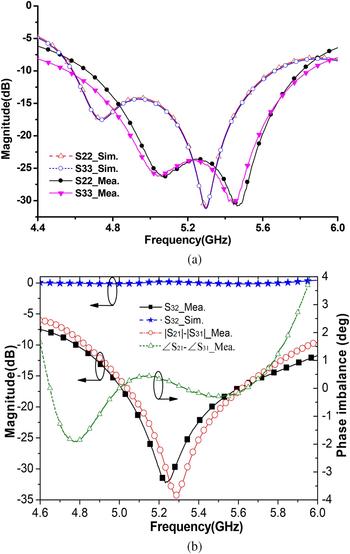
Fig. 5. Simulated and measured results: (a) output return loss and Photograph of the fabricated power divider, (b) isolation, magnitude, and phase imbalance.
Table 1. Comparison with other HMSIW power dividers
Conclusion
A novel Gysel HMSIW power divider has been presented in this letter. A HMSIW ring, three HMSIW–microstrip taper transitions, two microstrip stubs, and two isolation resistors have been applied to construct the presented Gysel power divider. The circuit structural sizes and parameters of the presented power divider can be obtained from the even- and odd-mode equivalent circuit analysis. Reasonable agreement between simulated and measured results can be observed. The developed Gysel HMSIW power divider has many advantages, such as wide bandwidth, good input/output impedance matching, relatively high output isolation, and high power-handling capability. It can be applied for microwave and millimeter-wave systems.
Acknowledgements
This work was supported by National Natural Science Foundation of China (Grant No: 61771094) and by the Research Fund of Shanghai Academy of Spaceflight Technology (Grant No: SAST2016094).
 Kaijun Song (M'09-SM'12) received the M.S. degree in radio physics and the Ph.D. degree in electromagnetic field and microwave technology from the University of Electronic Science and Technology of China (UESTC), Chengdu, China, in 2005 and 2007, respectively. Since 2007, he has been with the EHF Key Laboratory of Science, School of Electronic Engineering, UESTC, where he is currently a full Professor. His current research fields include microwave and millimeter-wave/THz power-combining technology; UWB circuits and technologies; microwave/millimeter-wave devices, circuits and systems; and microwave remote sensing technologies. Prof. Song is the Reviewer of tens of international journals, including Scientific Reports, IEEE Transactions, and IEEE Letters.
 Te Kong was born in Zhejiang, China in 1994. He received his Bachelor of engineering degree in electrical engineering from the University of Electronic Science and Technology of China (UESTC) in 2016. To date, he is working towards the Master degree in University of Electronic Science and Technology of China. His current research interests include microwave/millimeter-wave devices, circuits and systems.
 Yu Zhu was born in Anhui, China in 1992. He received his bachelor of engineering degree in electrical information engineering from Southeast University Chengxian College in 2014, and now he is trying to obtain his master degree in electrical engineering in University of Electronic Science and Technology of China (UESTC). His current research interests include millimeter-wave techniques with a focus on RF/microwave passive.