


Introduction
In modern communication systems, directive antennas are crucial components of the communication link. Due to its competitive performance, horn antennas are widely used in radar, satellite, and remote-sensing applications. However, since gain of the horn is related to its physical size, they become bulky and heavy in applications where high gain is required [Reference Balanis1]. The design of a high gain horn with smaller size would represent a remarkable achievement in this field. First attempts for this purpose proposed the usage of metamaterial with relative permittivity close to zero [Reference Hrabar, Bonefacic and Muha2–Reference Hrabar, Bonefacic and Muha6]. Metamaterial is a kind of artificial material that can exhibit anomalous relative permittivity and relative permeability values such as low-positive or negative within a certain frequency band [Reference Veselago7–Reference Valentine, Zhang, Zentgraf, Ulin-Avila, Genov, Bartal and Zhang9]. A grid-wire metamaterial structure is loaded at the aperture of the horn antenna and gain of the horn is boosted remarkably near the plasma frequency [Reference Hrabar, Bonefacic and Muha2]. Drude-like model reveals that the equivalent relative permittivity of the metamaterial is zero at plasma frequency, which results in more focused radiation beams [Reference Jackson10]. A new approach that uses epsilon-near-zero (ENZ) metamaterials to enhance the gain of a horn antenna over a broad frequency band is introduced [Reference Ramaccia, Scattone, Biotti and Toscano11]. With the focusing capability of the metamaterial structure, it may be considered as a flat lens. The metamaterial lens that consists of a two-layer grid wire with ENZ characteristics at the edges and epsilon-positive (EPS) characteristics around the horn axis is placed at the aperture of the horn. This concept is applied to the aperture of a conical horn antenna and proved its usage for 77 GHz radar systems [Reference Huang, Li, Sun, Sun and Tong12].
In this article, we present a three-layer, grid-wire metamaterial lens that consists of EPS and ENZ regions for pyramidal horn antenna using additive manufacturing (AM) instead of traditional processing techniques. AM or 3D printing technology has been used in various antenna and lens applications in a wide range of the electromagnetic spectrum, ranging from microwave to terahertz bands [Reference Yi, Qu, Ng, Chan and Bai13–Reference Zhang, Guo, Guo, Wu, Ng, Wong, Zhou and Huang21]. In the proposed manufacturing process, fused deposition modeling (FDM) is used to fabricate the horn antenna, whereas the grid-wire metamaterial lens is printed by selective laser sintering (SLS) due to the size limitation of the first method. Since both techniques are non-metallic, aerosol jetting is used to cover the printed surfaces with metal [Reference Castro, Babakhani and Sharma22, Reference Lomakin, Pavlenko, Ankenbrand, Sippel, Ringel, Scheetz, Klemm, Graf, Helmreich, Franke and Gold23]. The novelty of the article can be summarized as follows: (1) AM technique is used for the first time for the gain enhancement of a horn antenna with EPS-ENZ metamaterial lens. (2) A new procedure is introduced for the placement of a flat, metamaterial lens at the aperture of the horn antenna. With this technique, a three-layer EPS-ENZ metamaterial lens fits the tapered flaring of the horn and gain enhancement at a broader band is achieved compared to prior works [Reference Ramaccia, Scattone, Biotti and Toscano11, Reference Huang, Li, Sun, Sun and Tong12]. (3) The design of EPS-ENZ region located at the pyramidal horn aperture is asymmetric enabling low reflections. To the best of our knowledge, the plus-shaped EPS-ENZ metamaterial is applied to the asymmetric aperture for the first time in the literature. (4) 3D printing-based ENZ characteristics are demonstrated for the first time.
The operation of the metamaterial lens relies on the phase-compensation concept [Reference Ramaccia, Scattone, Biotti and Toscano11]. The phase shift inside the ENZ region is lower compared to that of free space (EPS region). The fields at edges interact with the ENZ region, whereas the fields propagating along the axis of the horn continues its path in free space. The structure of the EPS spacing and metamaterial lens is constructed to obtain uniform phase distribution on the phase-front after the lens. This resulted in improved gain characteristics over the frequency band of 10–18 GHz.
The structure of the paper is as follows: in section “ENZ metamaterial”, the characteristics of an ENZ slab and its unit cell solution consisting of metallic grids are presented. The design procedure and implementation of a metamaterial lens on to the aperture of the horn is explained in section “Design of a horn antenna with EPS/ENZ metamaterial lens”. The simulation and measurement results are given in “Simulation and measurement results” together with fabrication details. Finally, section “Conclusion” concludes the paper.
ENZ metamaterial
This section aims to design a grid-wire-based metamaterial unit structure providing ENZ operation. The field behaviors in a source-free ENZ region can be understood by studying Maxwell's equations written as follows:


where the magnetic field H is a curl-free vector. Furthermore, $\nabla ^2{\boldsymbol E}$ can be derived from (1) and (2), which means in such a medium electric field acts as a static-like distribution [Reference Alù, Silveirinha, Salandrino and Engheta24]. Inside the ENZ region, the magnitude of the electric field is infinitely large with respect to the adjacent regions, and the electric field magnitude can be defined as:

where ɛA and EA are the electric permittivity and electric field of the adjacent region, respectively [Reference Niu, Hu, Chu and Gong25, Reference Ciattoni, Rizza and Palange26]. According to (3) the electric field component has to show a sudden jump in magnitude when the electromagnetic wave enters the ENZ region with ɛENZ. Therefore, a proper metamaterial design indicating ENZ properties can enable the effective concentration of electromagnetic energy and its transmission without phase shift imposed by the curl-free magnetic field. An infinitely extended planar slab on the x-y plane with dMM thickness at z = 0 is illuminated with a normally incident plane wave. The transmission coefficient of a linearly polarized wave can be expressed as [27]:

where kMM is the wavenumber in metamaterial slab ($k_{MM} = \omega \sqrt {\varepsilon _{{\rm ENZ}}\;\mu _{{\rm ENZ}}}$ ); τ1 and τ2 are the transmission coefficients at z = 0 and z = dMM boundaries, respectively. Similarly, Γ1 and Γ2 are the reflection coefficients at these boundaries. The phase of the transmission coefficient given in (4) is plotted as the function of electrical thickness in Fig. 1. Different values of ɛ ENZ (μ ENZ = μ0) is observed. Figure 1 clearly demonstrates that the phase shift inside the slab is lower compared to that of free space. Also, lower phase shift is observed for smaller values of ɛ ENZ. Thus, the phase velocity of the wave is higher inside the slab compared to free space. To further understand the phase manipulation mechanism of the ENZ medium, the equation of the phase velocity will be a clear evidence which is written as follows:

where c represents the speed of light. As shown in (5), when the effective electric permittivity ɛeff becomes near zero, the phase velocity of the electromagnetic wave in the ENZ medium will be infinitely large. We can manipulate the phase front of the incident electromagnetic wave through a perfectly transmissive ENZ medium. This property is used to adjust non-uniform phase distribution on the aperture of the horn antenna. Proper usage of materials with different electrical permittivity results in uniform phase on the aperture.

Fig. 1. Phase variation of the transmission coefficient for a planar slab with ɛ ENZ and μ ENZ parameters excited by a normally incident plane wave.
Unit structure
In the design of the unit cell, the distance between rectangular conductor wires is set to h = 0.5λ around 10 GHz. Thus, the metamaterial structure acts as effectively homogeneous [Reference Ramaccia, Scattone, Biotti and Toscano11]. Three-layer grid wire with d = 6.8 mm between each grid layer is used. The width and thickness of the single rectangular conductor wire are 1 mm × 1 mm.
The plasma frequency of the unit cell is linked with the effective density of electron and mass influenced by the electromagnetic interaction between unit cell layers [Reference Pendry, Holden, Stewart and Youns28]. Drude-like model defines the equivalent epsilon of the unit cell as

where ωp and ω represent the plasma frequency of the grid wire and operation frequency, respectively.
To investigate the scattering performance (reflection and transmission), the unit structure shown in Fig. 2 is numerically simulated under normal incidence plane wave illumination. The perfectly electric conducting and the perfectly magnetic conducting boundary conditions are set parallel to the z-direction, and the open boundary condition is set along the z-direction.

Fig. 2. A unit structure of a three-layer grid-wire metamaterial. (a) Top view; (b) perspective view.
Simulated reflection and transmission spectra are shown in Fig. 3. The reflection coefficient poses two perfect reflection dips around 9.7 and 14.11 GHz. The designed unit structure provides an ultra-wide 3 dB transmission band from 8.5 to 17 GHz. Indeed, by studying (6), one can conclude that the plasma frequency overlaps with the first perfect reflection dip frequency (9.7 GHz), where the magnitude of the transmission coefficient is 1. When the ratio of ω 2p/ω 2 is close to 1, the refractive index n, i.e. the equivalent electrical permittivity ɛr, will be very close to zero, and the metamaterial starts to act as a perfect transmissive medium. Therefore, we can expect a rise in gain of the antenna just after 9.7 GHz when integrated with the grid-wire-based metamaterial lens. On the other hand, although the transmission is interrupted just above 17 GHz, the metamaterial lens works up to 18 GHz as shown in Fig. 3.

Fig. 3. Simulated reflection and transmission spectra of the designed wire-based metamaterial lens under normal incidence.
The dynamic range of the equivalent effective permittivity is ~0–0.9ɛ 0, corresponding to 9.7–16.5 GHz broad transmission band. Furthermore, the reflection and transmission spectra are same for both TE (transverse electric) and TM (transverse magnetic) polarizations due to the symmetrical geometry, and hence, the unit structure indicates polarization insensitivity.
A plane wave source at distance d source = 2λ excites the entrance face of the grid-wire medium with the length of dMM = λ/2 in air as shown in Fig. 4(a). In Fig. 4(b), the instantaneous electric field (Ey) amplitude is plotted for the case ω = ωp, i.e. at 9.7 GHz. It can be seen that the reflection coefficient is zero with the satisfied perfect impedance matching condition between air and ENZ medium. Electric field distributions at the entrance and exit faces of the ENZ medium are identical, showing the ENZ medium is perfectly transmissive. It is worth noting that the electrical field strength is strongly enhanced in the ENZ medium as expected, in line with (3). According to the conservation of energy, the Poynting vector (S ENZ) also significantly increases, which indicates the electromagnetic energy concentration skill of the ENZ medium. Furthermore, after passing the three grids of crossed metal wires, the net phase shift is zero, and the unit structure transmits the incident plane wave without phase change [Reference Li, Liu and Aydin29]. These outcomes reveal that grid-wire medium operates in the ENZ regime at 9.7 GHz. Indeed, the grid-wire metamaterial shows similar field characteristics up to 17 GHz, and therefore the ENZ regime is active over an ultra-wide band involving 9.7–17 GHz.

Fig. 4. Simulated electric field profile for plane wave propagation through the epsilon-near-zero grid-wire medium. (a) The concept showing a TE-polarized plane wave impinges from air to ENZ medium. (b) The electric field distribution in all regions for the case ω = ωp .
Design of a horn antenna with EPS/ENZ metamaterial lens
With their moderate gain, low voltage standing wave ratio, wide bandwidth, and simple manufacturing, horn antennas are commonly preferred in radar applications. The gain and directivity of a horn antenna are correlated to its physical dimensions, namely its length and aperture area. Generally, the length of the horn is increased or its aperture area is expanded to obtain higher gain. Therefore, a horn antenna with high gain becomes bulky. Here, a metamaterial lens is used to increase the gain of the horn antenna instead of adjusting its dimensions. This is achieved by placing the three-layer grid-wire structure at the aperture of the horn antenna. More uniform phase distribution at the aperture of the horn antenna is obtained by the usage of the metamaterial structure.
Pyramidal horn antenna design
A pyramidal horn antenna given in Fig. 5 is designed. Parameters of the antenna are shown on the E-plane and H-plane cut views of the antenna. The blue dashed line shows the long horn antenna with L length. The black solid line shows a horn antenna with a shorter length. The gain of the long horn antenna is obtained by adding the three-layer grid-wire metamaterial structure with d thickness to the aperture of the short horn antenna. The metamaterial lens structure is demonstrated with red in Fig. 5. As the electromagnetic wave propagates along the axis of the antenna, the phase distribution is deteriorated due to the side walls. By adding a metamaterial grid-wire structure whose relative permittivity is nearly zero at the aperture of the horn antenna, more homogenous distribution is obtained. Thus, the metamaterial consisting of two regions acts as a lens that focuses the energy. WR90 waveguide with HWG = 22.86 mm and WWG = 10.16 mm aperture dimensions and LWG = 35 mm length is used to guide the source energy. The aperture of the horn antenna has W = 107 mm and H = 138 mm dimensions.
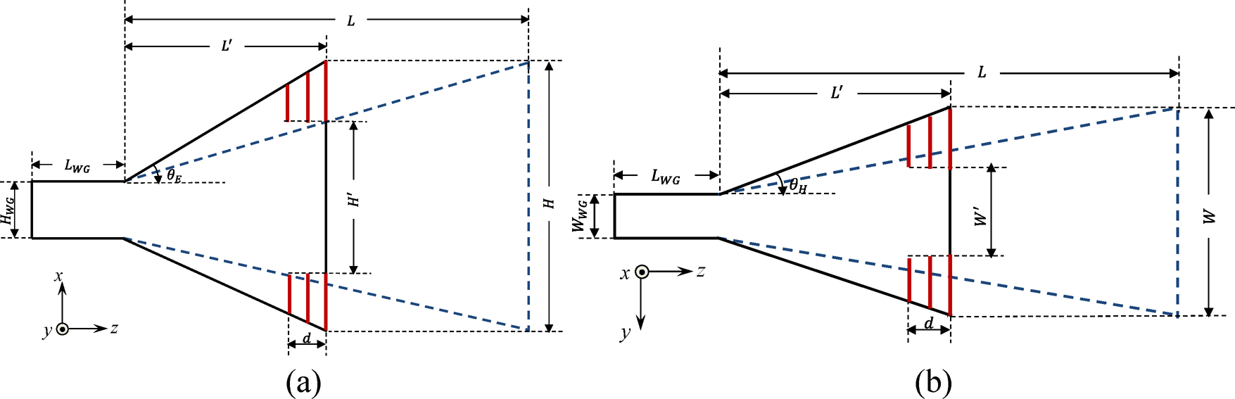
Fig. 5. Pyramidal horn antenna with L length (blue dashed line) and its shortened version (black solid line) with L′ = L/k (k is a constant) length and EPS-ENZ metamaterial. (a) E-plane, (b) H-plane.
The length of the short horn is set to L’ = 5λ 0, λ 0 is the free-space wavelength at 10 GHz. The gain of the short horn is enhanced to the gain of a long horn with L length by adding the grid-wire metamaterial. Thus, a more compact pyramidal horn antenna is obtained by adding conductor wires to the aperture of the antenna, which can easily be fabricated by standard manufacturing techniques.
Metamaterial lens design for pyramidal horn antenna
A metamaterial lens consisting of a grid-wire unit structure is placed at the aperture of the horn antenna to obtain more homogeneous phase distribution. Since the phase-shift is much lower in the ENZ slab compared to free-space, the phase velocity is higher in that region. More uniform phase distribution results in higher gain and directivity [Reference Chen, Ma, Zou, Jiang and Cui30]. The phase at the center and edge of the aperture can be expressed in terms of horn length L, metamaterial thickness d, and relative permittivity of metamaterial ɛMM [Reference Huang, Li, Sun, Sun and Tong12]:


where λ 0 is the free space wavelength and ɛMM,H and ɛMM,E are the relative permittivity at the center and edge, respectively. θ is the angular variation starting from the side walls of the horn, as shown in Fig. 5. It may be θE or θH depending on the plane of the horn. To have homogenous phase distribution on the aperture, |θ H − θ E| should be equal to zero. However, this is not possible when θ variation is accounted. This results as the need to design an inhomogeneous metamaterial. By setting θ H = θ E, the relative permittivity of metamaterial can be obtained as follows:

This variation is demonstrated for the metamaterial with 2d thickness in Fig. 6 as the function of θ. Although the curve changes little for angles θ < 10°, it ascends rapidly above. ɛMM is greater than the free space effective permittivity for θ > 21°. This figure proves the necessity to use a metamaterial with varying dimensions to ensure homogenous phase distribution.

Fig. 6. Effective permittivity variation of the metamaterial as the function of θ. Red dotted line demonstrates the free-space relative permittivity.
We designed the metamaterial lens consisting of two sections: (1) for θE < 6.5° and θH < 6.72°, three-layer metallic grids are used to ensure the ENZ characteristics; (2) above these angles, metamaterial is truncated and free space is left around the axis of the horn. The grids are truncated gradually at the corners due to the phase discontinuities at that region. The physical dimensions of the outermost layer of the grid-wire are shown in Fig. 7.

Fig. 7. Metamaterial lens for the horn aperture. The dimensions are given for the outermost layer in mm.
The dimensions of the other two layers are downsized according to the slope of the horn using (10)–(13) where d is set to 6.8 mm.


Simulation and measurement results
By loading the metamaterial lens consisting of ENZ and EPS materials at the aperture of the pyramidal horn antenna as shown in Fig. 8, gain enhancement is achieved. Performance of the horn antenna with the EPS-ENZ metamaterial lens is compared with that of the ordinary horn antenna.

Fig. 8. Horn antennas. (a) Ordinary 5λ horn antenna; (b) 5λ horn with EPS-ENZ metamaterial lens.
Simulation results
The numerical analyses of the antennas are carried out using 3D full-wave electromagnetic simulator of CST Microwave Studio Transient Solver based on the finite integration technique [31]. The horn antenna and the metamaterial lens are assumed to be made of copper. Reflection coefficient (S 11) variation of the 5λ horn and 5λ horn with metamaterial is demonstrated as the function of frequency in Fig. 9. In Fig. 9, the reflection coefficient variation of a horn with L = 10λ (k is set to 2) is also demonstrated.
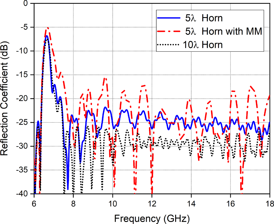
Fig. 9. Reflection coefficient variation of the horn antenna with EPS-ENZ metamaterial lens.
Above cut-off frequency of the waveguide, low reflection is observed. Although the presence of a metamaterial lens on the aperture of the antenna has negative effect on the reflection behavior, it is still below −15 dB in the whole frequency band. In Fig. 10, broadside gain of the horn antenna with a metamaterial lens is reported as the function of the frequency. The gain variation of the conventional horn is also exhibited together with long horn antenna. Horn antenna loaded with a metamaterial lens exhibits gain improvement at the frequencies above 9.7 GHz. Gain enhancement up to 3 dB is obtained. Loading the horn aperture with the metamaterial lens has a positive effect on the sidelobes, especially on θ = 0 plane. At 13.4 GHz, 5λ horn antenna with metamaterial has very close gain value to that of 10λ horn.
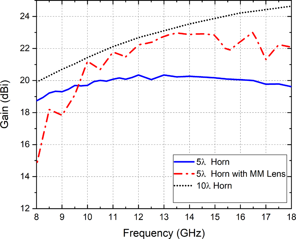
Fig. 10. Gain variation of the horn antenna with a metamaterial lens with respect to frequency.
The E- and H-plane patterns of the horn antenna are compared to that of horn antenna with a metamaterial lens at the 12, 14, and 16.5 GHz frequencies in Fig. 11. Solid lines belong to 5λ horn, whereas dash-dotted lines are that of horn antenna with a metamaterial lens. The patterns of the long horn are exhibited in the figure with black dotted lines, as well. The 1.89, 2.61, and 3.03 dB gain enhancements are achieved by loading EPS-ENZ metamaterial lens to the aperture of 5λ horn antenna at 12, 14, and 16.5 GHz, respectively.
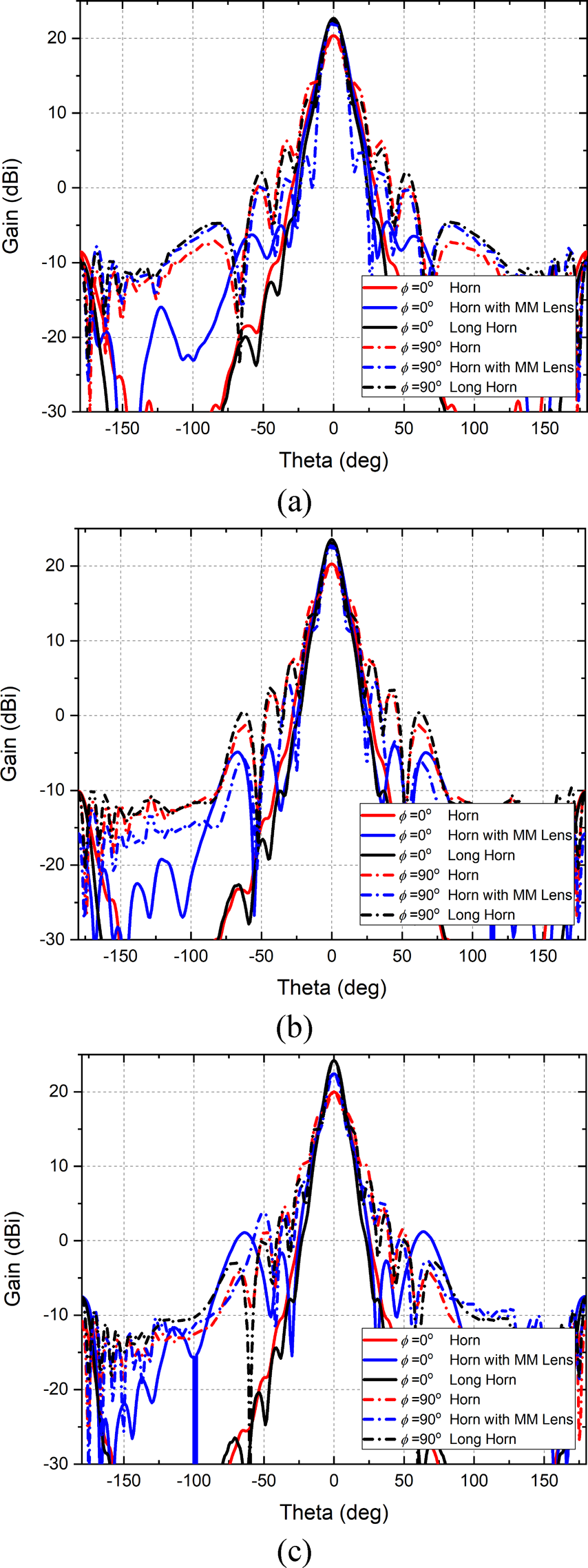
Fig. 11. E-and H-plane gain patterns of the horn antenna and horn antenna with metamaterial at (a) 12, (b) 14, and (c) 16.5 GHz. At 16.5 GHz, 3.03 dB gain enhancement is obtained compared to the conventional horn antenna with the same size.
Fabrication of the horn antenna with metamaterial lens
The fabrication process is illustrated in Fig. 12. The proposed fabrication is a hybrid method, and based on two different non-metallic 3D printing techniques: FDM and SLS. First, the 5λ horn antenna prototype is fabricated with FDM technique with polylactic acid (PLA) material using a commercially available 3D printer (Formiga-P 110 Velocis).
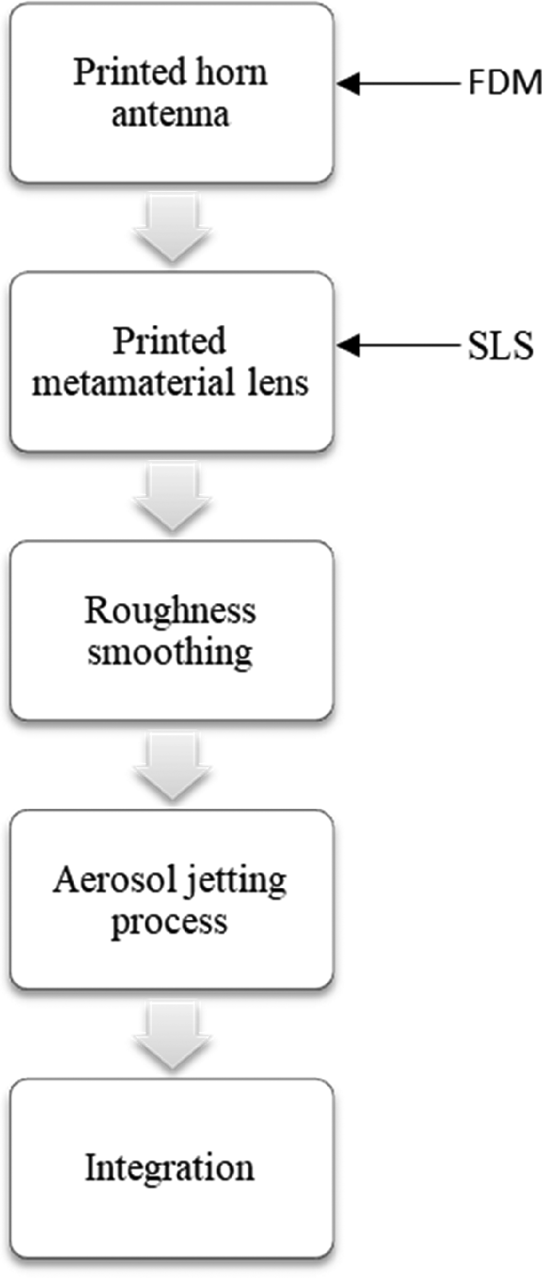
Fig. 12. Fabrication process involving fused deposition modeling and selective laser sintering.
The density of the print is set to 100%, and the diameter of the filament is 1.75 mm. The second step is the fabrication of EPS-ENZ metamaterial lens. Since the grids are too small (width × thickness: 1 mm × 1 mm) for manufacturing with FDM, SLS technique is used in lens fabrication. Polyamide material in powder form is the host material instead of PLA in the SLS process. After 3D printing, postprocessing, i.e. surface smoothing, is required to prevent decrease and fluctuations in the antenna gain, and increase the surface energy [Reference Garcia, Rumpf, Tsang and Barton32, Reference Byford, Ghazali, Karuppuswami, Wright and Chahal33].
The roughness on the inner surface of the antenna is removed with the help of aplastic sandpaper. Then, both the inner side of the horn antenna and the surface of the metamaterial lens are coated by a commercial nickel-based conductive aerosol (841AR) providing effective shielding over the operating frequency band. It is observed that the surface roughness decreases with metal deposition as expected [Reference Jun, Elibiary, Sanz-Izquierdo, Winchester, Bird and McCleland34]. After metallization, the metamaterial lens is integrated into the horn aperture via an applied adhesion layer. Due to the angular plane of the horn, a strong adhesion is achieved. The resulting prototype is demonstrated in Fig. 13. The horn with L = 5λ-d length is fabricated following the previous procedure.

Fig. 13. Prototype of 5λ horn with a metamaterial lens.
Measurement results
The experimental verification of the antennas was performed with the measurement setup given in Fig. 14. WR-90 waveguide to the coaxial adapter is used for transition. The measured reflection coefficient of the two antennas is shown in Fig. 15. Reflection coefficient for the horn antenna shows good impedance matching performance with S 11 lower than −10 dB within 7.3–14.8 GHz (1:2.02 BW) band. A 1:2.1 BW is observed for horn with a metamaterial lens.

Fig. 14. Measurement setup for the experimental verification of horn antennas.

Fig. 15. Measured reflection coefficient of the antennas as the function of frequency.
From the gain variation of the reference antenna, gain values of the antenna under test are determined. The measured and simulated gain variations of the 5λ horn with and without a metamaterial lens are plotted as the function of frequency in Fig. 16. The measured peak gain of the horn with a metamaterial lens is 23.59, 21.9, and 21.5 dBi at 12, 14, and 16 GHz, respectively. In the measurements, maximum gain enhancement is observed at 12 GHz which is about 3.5 dB. The discrepancy between gain values of simulation and measurement might come from fabrication uncertainties. Due to the physical dimension and fabrication technique of the grids, the lens profile does not remain planar. There are small bends at the inner corners of the grids. Although the printed lens has some deformations in its structure due to the unperfect manufacturing, the gain enhancement can be clearly observed in the measurements for a wide frequency band.

Fig. 16. Measured gain variation of the 5λ horn antenna with and without metamaterial as the function of frequency.
The gain improvement starts at 9 GHz in measurement. It was at 9.7 GHz in simulations. This is attributed to the deformation of the lens, as well. However, the results clearly show that deformations do not have a great impact on the radiation performance of the horn antenna.
Conclusion
In this work, we have presented a compact, low-cost, lightweight solution with a simple fabrication process for the enhancement of horn antenna gain. A flat, artificial lens consisting of EPS and ENZ regions is designed with three-layer metallic grids, and has been applied successfully to the aperture of a conventional pyramidal horn antenna. The design procedure of the lens structure and process for the 3D printed-based fabrication is introduced. The antenna performance obtained by both simulations and measurements clearly demonstrates the superior gain characteristics of the horn antenna with a metamaterial lens for a broad frequency band covering 10–18 GHz. Gain enhancement of up to 3 dB in simulations and 3.5 dB in measurements is obtained with the proposed metamaterial lens compared to the bare conventional horn antenna in the same size. Besides, it has been proved that both the horn antenna and aperture with a metamaterial lens can be exploited by the usage of a 3D printer. This result may open door to a comprehensive solution for satellite and radar systems as a high gain, compact, light-weighted, broadband radiator.
 Nesem Keskin received her B.Sc. degree in Electronics and Communication Engineering, and Electrical and Electronics Engineering from Halic University, Turkey, in 2009 and 2012, respectively. Currently, she is pursuing her Ph.D. degree in the Department of Electronics and Communications Engineering at Yildiz Technical University. Her current research interests are microstrips, horn antennas, and reflectors.
 Sinan Aksimsek received his B.Sc. degree in Electrical and Electronics Engineering, and his M.Sc. degree in Electronics and Telecommunication Engineering from Istanbul University and Istanbul Technical University, Istanbul, Turkey, in 2007 and 2010, respectively. He received his Ph.D. degree in Electronics Engineering from the Gebze Technical University, Kocaeli, Turkey, in 2014. From 2015 to 2016, he was a postdoctoral research fellow with the Department of Electronics and Nanoengineering, Aalto University, Finland. He is an assistant professor with the Department of Electrical and Electronics Engineering, İstanbul Kultur University, İstanbul, Turkey. His current research interests include mm-wave antenna technologies, printed and flexible RF devices, meta-surfaces/materials, electromagnetics of 2D materials, and graphene plasmonics.
 Nurhan Turker Tokan received her B.Sc. degree in Electronics and Communications Engineering from Kocaeli University in 2002 and her M.Sc. and Ph.D. degree in Communication Engineering from Yildiz Technical University (YTU), Istanbul, Turkey, in 2004 and 2009, respectively. From May 2003 to May 2009, she worked as a research assistant in the Electromagnetic Fields and Microwave Technique Section of the Electronics and Communication Engineering Department of YTU, Istanbul, Turkey. Between May 2009 and April 2015, she worked as an assistant professor in the Electronics and Communication Engineering Department of YTU. Since April 2015, she has been working as an associate professor at the same department. From October 2011 to October 2012, she was a postdoctoral researcher in the EEMCS Department of Delft University of Technology, Delft, The Netherlands. From October 2012 to May 2013, she was a postdoctoral fellow supported by the European Science Foundation at the Institute of Electronics and Telecommunications (IETR), University of Rennes 1, Rennes, France. She is the author or co-author of more than 50 papers published in peer-reviewed international journals and conference proceedings. Her current research interests are analysis and design of antennas with emphasis on dielectric lens antennas and wideband antennas, microwave circuits, and intelligent systems.


