


Introduction
Antennas with wide impedance bandwidth, lightweight, high gain, low-cost, and low-profile features play a vital role in modern wireless communication systems. Studies of different low-profile wideband antennas are presented in [Reference Feng, Zhai, Xi, Yang, Zhang and Yang1–Reference Tran, Trong, Le, Abbosh and Park4]. Feng et al. [Reference Feng, Zhai, Xi, Yang, Zhang and Yang1] have proposed a broadband circularly polarized antenna using artificial magnetic conductor (AMC). In [Reference Zhu, Li, Liao and Xu2], a MIMO antenna with AMC ground plane with 31% impedance bandwidth has been presented. Lin et al. [Reference Lin, Chen, Ziolkowski and Guo3] have presented a wideband, compact, and high gain reconfigurable antenna. To minimize the overall profile, the polarization independent AMC has been used in [Reference Lin, Chen, Ziolkowski and Guo3]. A low-profile, wideband, high gain reconfigurable antenna for polarization diversity has been proposed in [Reference Tran, Trong, Le, Abbosh and Park4].
An AMC-loaded patch antenna with wideband performance for C-band/WLAN/5G has been proposed in [Reference Ntawangaheza, Sun, Yang, Pang and Rushingabigwi5]. Another wideband antenna with higher 3 dB bandwidth has been proposed in [Reference Mohammad Lou and Moghadasi6] to cover the entire C-band. Wong and Chien [Reference Wong and Chien7] have proposed a wideband monopole antenna operating at WLAN band for mobile phones. Chen et al. [Reference Chen, Zhang, Yang, Zhang and Zeng8] have proposed an wideband, high gain circularly polarized antenna by using a $4\times 4$ polarization rotating reflective surface cell. Liu et al. [Reference Liu, Di, Liu, Wu and Tentzeris9] have proposed a broadband, high gain antenna for off-body communication. The paper also introduces AMC ground plane to achieve off-body communication. A low-profile AMC-based antenna for achieving wide impedance bandwidth, high gain, and lower specific absorption rate (SAR) has been proposed in [Reference Cao, Zhang and Mo10]. An integrated monopole antenna with 70% SAR reduction has been proposed in [Reference Bulla, Salles and Fernndez-Rodríguez11]. Hazarika et al. [Reference Hazarika, Basu and Kumar12] have proposed an integrated antenna to reduce 1-g averaged SAR for WBAN application.
The paper has exploited a wideband, low-profile, compact high gain staircase pattern defected ground monopole to enhance the radiation properties when incorporated with wideband AMC surface at 0.27$\lambda$ air gap. Both the layers are fabricated on a lossy FR4 substrate. The study has proposed $2\times 2$
 array of slotted staircase patterned unit-cells providing zero reflection phase at 6.57 GHz. blueThe AMC proffers polarization independent behavior in the respective frequency band depicting robustness in AMC reflection phase characteristics. The monopole resonating near 7.39 GHz have used defected neck type ground structure to model the antenna surface inductive near 8.15 GHz which upon integration with the capacitive AMC surface excites two resonating bands near 6.5 and 8.15 GHz to target the C-band (4–8 GHz) and ITU band (8.01–8.5 GHz) respectively. The defected neck type ground structure has enhanced the $-$
 10 dB bandwidth up to 42.8 and 34.1% at the designated frequency band. The periodic AMC has contributed MU-negative (MNG) characteristics and negative refractive index and effectively transformed the spherical-like phase criterion of the transmitted wave into in-phase planar criterion, and improved the maximum gain up to 9.7 dB. blueBy using staircase symmetrical patch instead of conventional one, a significant reduction of the size of the antenna is realized. The integrated structure has also achieved front to back radiation ratio (FBR) and efficiency up to 14.5 dB and $\gt$
 90% at the respective band. Because of the alteration of the material properties, AMC surface acts as a high impedance surface which shields backward electromagnetic radiation. Hence, 1-g averaged SAR is reduced up to 0.223 and 0.324 W/kg at the two designated bands which are significantly lower than the values reported in various recent articles. Impedance bandwidth and gain remain unperturbed due to artificial human loading which validates the excellence of antenna for an off-body communication system.
Planar AMC design
Reflection phase analysis
Figures 1(a)–(1c) show the physical configuration of type-1, type-2, and proposed wideband unit-cells, respectively. It comprises $2\times 2$ periodical patch unit-cells backed with continuous ground surface fabricated on top of the substrate. The AMC layer is fabricated on an FR4 Epoxy substrate having thickness of 1.6 mm, relative permittivity of $\varepsilon _r = 4.4$
 , and loss tangent of tan $\delta = 0.02$
 . The overall size of the AMC is $30\times 30$
 mm$^{2}$
 by considering the optimum dimension. By introducing the cut on the patch of unit-cell, the bandwidth of the proposed AMC antenna can be flexibly adjusted. To recognize the various electromagnetic features of the unit-cell, the simulation model using Floquet-port and air-filled waveguide with master–slave boundary conditions is utilized. The slotted AMC acts as a perfect magnetic conductor at the respective frequency band where deembedded zero reflection phase is obtained. The master–slave boundary conditions at the master are enforced on the slaves surface to realize the infinite periodic repetition. By applying this periodic boundaries on a unit-cell, the properties of an infinite number of unit-cells is achieved.

Fig. 1. (a) Type-1, (b) Type-2, (c) proposed and (d) reflection phases of unit-cell; (e) equivalent circuit, and (f) dispersion diagram of the proposed AMC.
The AMC structures have exploited as a phase-compensation surface to attain in-phase field profile. The in-phase reflection takes place between +90$^\circ$ and $-$
 90$^\circ$
 where the constructive signal interferences occur between the incident and the reflected waves. The impacts of the various AMC designs are examined to demonstrate its effect on in-phase reflection bandwidth. Hence, three different unit-cell patterns: type-1, type-2, and the proposed structure as presented in Figs 1(a)–1(c) are verified. It is demonstrated in Fig. 1(d) that, type-1 offers 17.2%, type-2 offers 17.8%, and bluethe proposed AMC design offers the widest 18.5% (6.10–7.32 GHz) $\pm 90^\circ$
 reflection phase bandwidth. The AMC design uses a slotted staircase pattern which has the ability of tuning the AMC bandwidth.
The reason for obtaining higher bandwidth than that of type-I and type-II AMC structures can be explained with the effective equivalent circuit model depicted in Fig. 1(e). The resonant frequency ($\, f_{r}$ ) corresponding to the equivalent circuit can be expressed as [Reference Raad, Abbosh, Al-Rizzo and Rucker13]:

where $L_{g}$ and $L_{d}$
 are grid inductance and dielectric slab inductance and $C_{g}$
 is the grid capacitance. $C_{g}$
 exists between two parallel patches as in Fig. 1(e) and can be extracted using

Here, $W$ is the AMC width, $g$
 is the gap between two adjacent cells, $\Delta L$
 is the length of the cut of the unit cell, and $a = 2\Delta L + g$
 . The design can be miniaturized via increasing one of the succeeding specifications: $L_{g}$
 , $L_{d}$
 , and $C_{g}$
 . Enhancing $L_{d}$
 leads to a larger profile. $C_{g}$
 can be increased via enhancing either $\Delta L$
 to $g$
 ratio or dielectric loading. In this design suitable choice of $\Delta L$
 and $g$
 causes $( a/g)$
 ratio to increase which in turn improves $C_{g}$
 as in equation (2). Rectangular slots are introduced in the AMC geometry to modify the current path which increases the $L_{g}$
 :
:
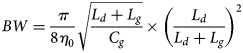
It is evident from equation (3) that the bandwidth will be narrower due to the increase of $L_{g}$ rather than $C_{g}$
 . Hence, we focus more on increasing the value of the shunt capacitance $C_{g}$
 to achieve miniaturized structure as well as higher bandwidth.
Dispersion diagram
In addition to reflection phase diagram, we have plotted the dispersion diagram [Reference Sievenpiper, Zhang, Jimenez Broas, Alexopolous and Yablonovitch14] of the AMC and shown in Fig. 1(f). From the figure, it is observed that a surface-wave band gap is located from 4 to 4.5 GHz, whereas the AMC zero reflection frequency is at 6.57 GHz. Since there exists only an in-phase reflection bandwidth and no surface-wave band gap at the designated frequency, it is referred as an AMC unit-cell not AMC-BG (AMC band gap).
Reflection phase characterization for different incidence angles
The angular stability of an AMC design is crucial to see the robustness in AMC reflection phase band. Various examinations have been done [Reference Cos, lvarez, Hadarig and Las-Heraset15, Reference Hadarig, Cos and Las-Heras16] and revealed that the AMC acts as polarization independent considering symmetric (isotropic) unit-cells. Hence the reflection phase analysis of TE (transverse electric) and TM (transverse magnetic) polarized waves for various incident angles under normal and oblique incidence are depicted in Fig. 2.

Fig. 2. Reflection phase of the AMC for different polarization angles for (a, c) TE and (b, d) TM under normal and oblique incidence.
For normal incidence
By taking symmetrical unit-cell, the angle of polarization is varied from 0 to 180$^\circ$ for TE-polarized wave (Fig. 2(a)). When the polarization angle is varied from 0 to 30$^\circ$
 and from 150 to 180$^\circ$
 , there is no variation with respect to resonance frequency and AMC operational bandwidth. However, the resonance frequency has shifted near 5.8 from 6.57 GHz and bandwidth has also become reduced when polarization angle ranges from 40 to 140$^\circ$
 .
.
In case of TM-polarized wave, for polarization angle ranging from 60 to 120$^\circ$ , the resonance frequency as well as AMC operational bandwidth remain unchanged. Whereas, from 0 to 50$^\circ$
 and 130 to 180$^\circ$
 , the resonance frequency shifts near 5.8 from 6.57 GHz and the operational bandwidth decreases to 10.5%. Therefore, when the fundamental mode of an antenna is a TM mode, under normal incidence, the AMC-integrated antenna will radiate exactly at 6.57 GHz band where the polarization angle ranges from 60 to 120$^\circ$
 as seen in Fig. 2(b).
For oblique incidence
Figure 2(c) presents the reflection phase plot for TE and TM for various polarization angles under oblique incidence. If the polarization angle is varied from 0 to 180$^\circ$ for TE-polarized wave, there is no deviation in zero phase reflection point, but the AMC bandwidth degrades for some polarization angles. When the polarization angle is varied from 0 to 30$^\circ$
 and from 150 to 180$^\circ$
 , there is no variation of bandwidth. However, from 40 to 140$^\circ$
 , the AMC bandwidth degrades from 18.5 to 15%.
In case of TM, the operating frequency of the AMC for entire polarization angles are shifted to 5.65 GHz for 0 and 180$^\circ$ under oblique incidence as shown in Fig. 2(d). Although the unit-cell is illuminated with incident plane wave with polarization angles from 0 to 50$^\circ$
 and from 130 to 180$^\circ$
 , it has met same operational bandwidth. However from 60 to 120$^\circ$
 , the AMC bandwidth enhances with a variation of resonance frequency.
Material parameters of unit-cell
To characterize the reported unit-cell, its reflection and transmission parameters are extricated by employing master–slave boundaries using Ansys HFSS. Extraction of the scattering parameters of the proposed AMC requires an infinite repetition of the unit cell in the lattice vectors direction. The Floquet port is capable of simulating obliquely incident plane waves and used with the master–slave boundary conditions. Applying periodic boundaries to the unit-cell, the $S$ -parameters: $S_{11}$
 and $S_{21}$
 , are extricated blue [Reference Kumar and Vishwakarma17]. With the $S_{11}$
 and $S_{21}$
 values, the permittivity ($\varepsilon$
 ) and permeability ($\mu$
 ) are calculated according to equations (4) and (5) [Reference Ziolkowski18], and presented in Figs 3(a) and 3(b). From Fig. 3(a), it is observed that the magnitude of the permittivity is near zero (slightly positive) and the magnitude of permeability is negative. It provides the large positive wave impedance ($z$
 ) and negative index of refraction ($n$
 ) which is eventually reflected in Fig. 3(c) [Reference Ahmad and Mohammad19]. blueThe extracted material parameter graph in Fig. 3(a), shows that the proposed wideband unit-cell behaves as MNG material in the frequency range of 6.10–7.32 GHz:


where $l_{1}$ is the maximum length of the unit cell, and $k_{0}$
 is the wave number.

Fig. 3. Characterization of unit-cell: (a) re $\varepsilon$ , $\mu$
 (b) im $\varepsilon$
 , $\mu$
 and (c) re $n,\; z$
 (d) im $n,\; z$
 .
.
Design of low-profile printed monopole
We have designed staircase monopole antenna and optimized the dimensions (refer to Table 1) to get reflection coefficients near 7.39 GHz. blueThe final structure consists of two layers: monopole with defected ground on top and $2\times 2$ AMC array on bottom. The layers are separated by an air gap of 6.5 mm. In practical applications, air gap is realized using a foam layer having dielectric constant nearly equal to 1 (similar to air). The structure of integrated wideband antenna and its fabricated prototype with all views are displayed in Fig. 4(a) and Figs 4(c)–4(f). The antenna comprises two symmetrical staircase shaped structure on top and defected ground plane on bottom which are printed on lossy FR4 epoxy with a dielectric height of 1.6 mm, dielectric permittivity of 4.4 and loss tangent of 0.02. blueThe equivalent circuit model for the proposed monopole is presented in Fig. 4(g). The feed line is represented by a capacitance $C_{s}$
 [Reference Oraizi and Rezaei20]. The parallel $L_{a}$
 , $C_{a}$
 , and $R_{a}$
 represent the equivalent inductance capacitance and resistance of the monopole corresponding to its resonance at 7.39 GHz and referred as $Z_{p}$
 . The stair case structure with partial ground plane with an arc at the center modify the $C_{a}$
 , and $L_{a}$
 so that the antenna resonates at 6.64–8.24 GHz which closely matches with the $\pm 90^\circ$
 reflection phase bandwidth of AMC (6.10–7.32 GHz). Significant reduction of the size of the antenna is realized when the staircase patch is used instead of the conventional one. The size of the proposed staircase antenna is (0.14 $\lambda \,\times$
 0.41$\, \lambda \, \times \,$
 0.07$\lambda$
 ). It has been observed that the simulated $S_{11}$
 , gain and efficiency of the AMC-integrated antennas are all similar for various array sizes. So it has used $2\times 2$
 array of the slotted cells (Fig. 4(b)) to obtain the smallest possible size.

Fig. 4. (a) Integrated antenna layout; (b) $2\times 2$ array AMC, and integrated antenna; (c) top, (d) bottom, (e) side, (f) prospective views of the prototype; and (g) equivalent circuit of monopole antenna.
Table 1. Dimensions of wideband monopole (mm)

Simulation and measurement results
Reflection coefficient analysis
The reflection coefficient measurement of the proposed design is done utilizing an Agilent MS2037 C vector network analyzer (VNA). Figures 5(a) and 5(b) show the simulated and measured reflection coefficients of the monopole alone and integrated antenna. blueThe staircase slots length and width are carefully selected to resonate at 7.39 GHz. Moreover, widening of the bandwidth takes place owing to the modification of the capacitive and inductive effects caused by the electromagnetic coupling effect between the staircase patch and partial ground plane. The antenna has achieved frequency band from 6.64 to 8.24 GHz with reflection coefficient $\lt\!\! -$ 10 dB as shown in Fig. 5(a). blueThe defected neck type ground structure below monopole has enhanced the $-$
 10 dB bandwidth up to 42.8 and 34.1% at the two frequency bands while incorporating with AMC. We have analyzed the simulated $S_{11}$
 of AMC-integrated antenna for different FR4 thicknesses and found that, the substrate with thickness 1.6 mm offers dual resonance with best impedance matching performances and so chosen for the proposed structure.

Fig. 5. Reflection coefficient of (a) monopole alone and (b) integrated antenna with inset VNA output; simulated (c) $S_{11}$ and (d) gain of integrated antenna at different air gaps.
Radiation analysis
At first, we have simulated the proposed antenna with various air gaps and presented in Figs 5(c) and 5(d). blueThe gap between monopole and AMC is essential and optimized to attain good reflection coefficient. Adding the air layer effectively enhances the bandwidth as well as proffers better impedance matching [Reference Zeng, Chen, Qing and Jin21]. As shown in Fig. 5(c), the bandwidth becomes maximum for the air layer 6.5 mm. Eventually, as the gap varies from 6.5 mm, the maximum gain also reduces (Fig. 5(d)). Hence, to achieve maximum bandwidth and better radiation performances, we have used air gap of 6.5 mm (realized using foam layer) between AMC and monopole.
To examine the radiation characteristics of the monopole and integrated antenna, the simulated and measured radiation patterns in the $xy$ -planes have been performed. The staircase antenna has achieved monopole kind pattern in the $E$
 -field and omnidirectional criterion in the $H$
 -field at 7.39 GHz frequency band as shown in Figs 6(a) and 6(b). The isolation between co and x-pol for $E$
 -field pattern at broadside direction is 44 dB at 6.5 GHz as shown in Fig. 7(a). Whereas at 8.15 GHz, the isolation between co and x-pol for $E$
 -field is 32 dB as shown in Fig. 7(c). Again for $H$
 -field, co-x pol isolation of 44 and 32 dB have been obtained at 6.5 and 8.15 GHz respectively as shown in Figs 7(b) and 7(d). The AMC surface with full ground plane at the back reduces backward radiation and enhances gain.

Fig. 6. Configuration of (a) $E$ -field and (b) $H$
 -field of monopole antenna at 7.39 GHz.

Fig. 7. (a, c) $E$ -field, (b, d) $H$
 -field of integrated antenna at 6.5 and 8.15 GHz.
blueWhen the AMC layer with full ground at the back is located near to the monopole, it functions as infinite layer, and reduces the edge effect which helped to enhance the antenna gain. The simulated and measured peak gain of monopole and the integrated antenna are presented in Fig. 8(a). It is seen that the only monopole has achieved peak gain of 3.67 dB while the integrated antenna has achieved maximum gain up to 9.7 dB and possess reasonably good gain over the entire resonating frequency band bluethan that of other published studies [Reference Kumar and Vishwakarma22, Reference Kumar and Vishwakarma23]. The minor discrepancy occurs between simulated and measured results due to fabrication loss and cabling error. It is observed that the staircase antenna has FBR of 5.4 dB at 7.39 GHz, whereas the blueintegrated antenna has 9.7 and 14.7 dB at 6.5 and 8.15 GHz respectively (Fig. 8(b)). The integrated antenna also behaves as a high efficiency antenna with 0.97 and 0.95 simulated efficiency at 6.5 and 8.15 GHz respectively as shown in Fig. 8(c). Whereas if the gap between antenna and AMC is reduced the radiation efficiency degrades due to coupling between them. These results are measured using a fully automatic anechoic chamber (Fig. 8(c)) having pyramidal absorbers with a reference horn antenna and a VNA.

Fig. 8. (a) Gain, (b) FBR, and (c) simulated efficiency with inset anechoic chamber setup of wideband antenna.
The existence of the various propagation modes of the antenna is revealed by the vector electric-field variation (VEFV) along the vertical edges of the substrate assessing the resonant cavity model. Hence to explain the propagation modes, the substrate sizes are shortened to the length and width of the monopole and VEFV are analyzed for the vertical sides of substrate and presented in Figs 9(a) and 9(b). It is proved that, at 6.5 and 8.15 GHz, the VEFV are showing a single half wave cycle toward the length of the antenna and no wavelength variation along width, thus ensures the excitation of ${\rm TM}_{10}$ [Reference Chen, Zhang, Shao and Zhong24] mode. Figures 10(a) and 10(b) present the surface current distributions of the integrated antenna at both the frequencies. It is observed that the lower surface current distribution of the integrated antenna signifies the higher electric-field distribution through the step shaped wideband antenna.

Fig. 9. Electric field variation of wideband antenna at: (a) 6.5 GHz and (b) 8.15 GHz.
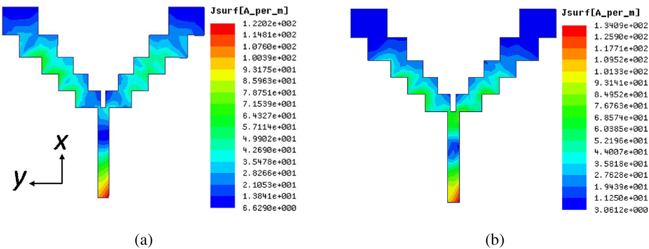
Fig. 10. Surface current distributions of integrated antenna at: (a) 6.5 GHz and (b) 8.15 GHz.
Artificial human body model
To examine the off-body performance of the antenna, a four layer artificial body phantom which validate the different electromagnetic properties of the human tissues is required. Each artificial human body layer is comprised of different mass density, relative dielectric constant ($\varepsilon _r$ ), conductivity ($\sigma$
 ), and thickness values. In this paper, the proposed structure is aimed to be implanted on the skin. Hence, we have taken a ($90\times 90\times 42$
 ) mm$^{3}$
 multilayered simulation model comprised of 2 mm of skin, 5 mm of fat, 40 mm of muscle, and 13 mm bone as presented in Fig. 11(a). The antenna is put above the skin, at different distances ($d_g$
 ) from the air–skin interface. The material properties of the human tissues are well explained in [Reference Gabriel, Lau and Gabriel25] from 10 Hz to 20 GHz.

Fig. 11. (a) Artificial phantom; 1-g averaged SAR of (b) monopole, integrated antenna at (c) 6.5 GHz and (d) 8.15 GHz.
SAR analysis
To assess the effects of the design on artificial body tissues, the SAR analysis is done in ANSYS HFSS using formulated EM parameters (Table 2) [Reference Gao, Hu, Wang and Yang26]. The maximum 1-g SAR of only monopole is 4.27 W/kg at 7.39 GHz (Fig. 11(b)), which is above the U.S. guidelines of 1.6 W/kg and the European guidelines of 2.0 W/kg. Placement of the AMC layer at an air gap of 6.5 mm below the monopole mitigates backward radiation. Because of the modification of the material properties, AMC surface acts as a high impedance surface causing back shielding of the EM radiation. It is seen from Figs 11(c) and 11(d) that, including the AMC beneath the antenna, scatters the EM transmission in other directions. blueThe maximum 1-g SAR value at 6.5 GHz is 0.223 W/kg at $d_g =$ 1 mm, which is 94.8% lower than that of the antenna without AMC as shown in Fig. 11(c). For 8.15 GHz, the maximum 1-g SAR is 0.324 W/kg, which is 92.4% lesser than that of without AMC as shown in Fig. 11(d). The structure reduces SAR values as the proposed AMC layer with the full ground plane at the back shields most of the backward radiation. The SAR values are evaluated using 100 mW power and listed in Table 3. The AMC antenna also reduces 1-g SAR up to 0.110 and 0.105 W/kg when it is 5 mm away from skin.
Table 2. Material properties for the artificial tissue-layers

Table 3. SAR analysis of monopole and integrated antennas at various distances

S-parameter analysis on human skin
To establish the impact of human body, the integrated antenna is situated above the skin of artificial phantom and $S_{11}$ parameter is analyzed. Figure 12(a) presents the simulated $S_{11}$
 of the integrated antenna in free space and on skin 1 and 3 mm apart. There is a small variation in resonating frequency when the antenna is placed on the skin. This shifting occurs because of the dielectric variation of the antenna in the presence of artificial human tissues. The integrated antenna offers peak gain up to 8.4 and 8.2 dB when it is 1 and 3 mm apart from skin as shown in Fig. 12(b). The reduction of the gain occurs due to high dissipation caused by the surrounding human tissues.

Fig. 12. Variation of (a) $S_{11}$ and (b) gain in human loading.
The proposed antenna is designed mainly at C-band for off-body communications like antennas reported in [Reference Liu, Di, Liu, Wu and Tentzeris9, Reference Cao, Zhang and Mo10]. Hence, 1-g averaged SAR is reduced up to 0.223 and 0.324 W/kg at the two designated bands are significantly lower than the values reported in various recent papers [Reference Liu, Di, Liu, Wu and Tentzeris9, Reference Cao, Zhang and Mo10]. Our proposed antenna can be placed on cloth pockets, handbags, etc. as a sensor for WBAN applications. Moreover, blueimpedance bandwidth and gain remain unperturbed due to artificial human loading (Figs 12(a) and 12(b)) which also proves the appropriateness of antenna for an off-body communication system.
Table 4 compares the main characteristics of the integrated structure with some other reported antennas. Based on the overall performances, the proposed FR4-based structure is better than the antennas reported in Table 4 concerning some useful aspects.
Table 4. Comparison with some reported studies

Conclusion
A wideband, compact, staircase-patterned low-profile integrated antenna operating at 6.5 and 8.15 GHz has been achieved. The planar AMC has achieved 18.5% reflection phase profile ranging from 6.10 to 7.32 GHz and manifests MNG properties. The AMC proffers polarization independent behavior in the respective frequency band which depicts robustness in AMC reflection phase characteristics. However, the integrated antenna has an impedance bandwidth of 2.71 GHz ranging from 5.93 to 8.64 GHz. Moreover, the integration of wideband AMC beneath the staircase monopole antenna alters the out-of-phase radiation to in-phase planer pattern which increases the antenna gain. Enhanced FBR and efficiency have also been obtained by the integrated antenna design. The proposed design has also reduced 1-g averaged SAR by 94.8% while kept 1 mm distance away from skin. Impedance bandwidth and gain remain unperturbed due to artificial human loading which proves the superiority of antenna for an off-body communication system. Due to the wideband and high gain features, the antenna can be used for early detection of breast cancer.
 Bidisha Hazarika received her Bachelor of Engineering degree in electronics and telecommunication engineering from Guwahati University, Assam, India, in 2014, and the MTech degree in communication and signal processing engineering from National Institute of Technology, Silchar, Assam, India in 2017. She is currently pursuing PhD degree in electronics and communication engineering from National Institute of Technology, Silchar, India. Her research interests include metamaterial-based antennas and artificial magnetic conductor (AMC) structures and flexible antenna design.
 Banani Basu received her BTech degree from Jalpaiguri Government Engineering College, India, in 2004, MTech degree from West Bengal University of Technology, India in 2008 and PhD from National Institute of Technology, Durgapur, India in 2012, all in electronics and communication engineering. She is the senior member of IEEE. Currently, she is working as an assistant professor in the Department of ECE, NIT Silchar, India. Her research interests include metamaterial-based antennas and artificial magnetic conductor structures and soft computing techniques for antenna design.
 Arnab Nandi received his BTech degree from Kalyani Government Engineering College, India, in 2003, MTech degree from University of Burdwan, India in 2005 and Ph.D. from National Institute of Technology, Durgapur, India in 2012, all in electronics and communication engineering. Currently, he is an assistant professor in the Department of ECE, NIT Silchar, India. His research interests include ad-hoc wireless networks, wireless sensor networks, cross layer issues, medium access control, antenna design, and artificial magnetic conductor structures.


