


Introduction
The development of wireless communication increases the needs in miniaturized and integrated antennas. These miniaturization and integration are very useful for low-frequency applications (VHF/UHF bands) and for general public applications, such as frequency modulation (FM) radio reception on mobile phones and tablets. It induces a growing demand for small FM antennas. For mobile phones and tablets, antenna integration is required to replace the external antenna located in the headphone wires. For automotive applications, the FM antenna is most of the time placed on the top of the roof and is subject to urban damage and need mechanical placement (roof drilling that could add tightness problems). For these kinds of application, the development of optically transparent and electrically small antennas printed onto the glass (screen or automotive window) is completely relevant. That is the purpose of the present study.
Many passive designs have largely been investigated to get electrically small antennas such as meandering, helical, patch, dielectric resonator antennas, etc. [Reference Huitema1]. These designs can be combined with materials [Reference Manac'h, Castel and Himdi2,Reference Kocia and Hum3] for a better integration into structural panels. They can also include passive and active components [Reference Taachouche, Colombel and Himdi4] to further improve size reduction or to add new functionalities, such as frequency tunability [Reference Martin, Castel, Lafond and Himdi5].
For this study, we select two complementary routes to fabricate an electrically small antenna: a meandering design associated with an active component. In addition, the antenna will be optically transparent for a better implementation on glazed surfaces such as car windows. The main difficulty in the fabrication of such antennas lies in the development of materials combining both a high electrical conductivity and a high level of optical transparency. Some materials meet the two criteria, such as those belonging to the transparent conducting oxide (TCO) family [Reference Kocia and Hum3,Reference Awalludin, Ali and Mamat6], TCO/metal multilayers [Reference Hong, Kang and Jung7–Reference Hong, Kim and Jung9], metal nanowires [Reference Kim, Shin, Pyo, Lee, Son, Lee and Park10], and conductive polymers [Reference Guerchouche, Herth, Calvet, Rolland and Loyez11]. However, these solutions involve radiofrequency loss due to the sheet resistance of the layers higher than 1 Ω/sq (Table 1), which restricts the antenna performance and increases the power consumption. A solution has been specifically developed in the Laboratory for this kind of application: the micrometric mesh silver layer, which provides a high level of optical transparency with a low-sheet resistance value [Reference Hautcoeur, Castel, Colombel, Benzerga, Himdi, Legeay and Motta-Cruz12] (Table 1).
Table 1. Electrical and optical performance of transparent and conducting materials

In this study, we present a small transparent FM receiving antenna. The printed meandering monopole antenna is designed to operate in the FM radio band (88–108 MHz). Miniaturization of the FM antenna is also improved by the use of a MESFET transistor (MEtal Semiconductor Field Effect Transistor). Optical transparency is achieved thanks to a transparent and conducting mesh silver layer printed ontoa glass substrate. This paper is organized as follows. The antenna design and fabrication are first detailed. Then numerical simulations are presented in the section “Numerical results and radiofrequency measurements”. Measurements of the received signal strength indicator (RSSI) and of the signal-to-noise ratio (SNR) are also presented and compared with those of a commercial wire monopole antenna. Finally, the conclusion is drawn in the section“Conclusion”.
Antenna design and fabrication
The structure of the studied active receiving antenna is inspired from [Reference Taachouche, Colombel and Himdi4] and depicted in Fig. 1. The antenna combines a meandering monopole with a MESFET transistor (ATF 21100). The printed wire monopole antenna shows a quasi-omnidirectional radiation pattern, such as that of commercial FM antennas located on the vehicle roofs. The substrate used is a 101.6 mm × 101.6 mm × 0.7 mm 1737 Corning Glass with a dielectric permittivity  $\epsilon _r=$ 5.7, a loss tangent
  $\tan \delta =$ 0.006 at 2 GHz and an optical transparency
  $T_{sub}=$ 92% in the visible light spectrum (due to Fresnel loss). The wire length (295.4 mm) and its width (8 mm) comply with a quarter-wave monopole antenna design. The number of meanders has been selected here for printing the antenna onto a square area (each side measuring ~80 mm), thus locating the covered area. Furthermore, the reversal of the main current propagation direction in each successive meander restricts the cross-polarization in the H-plane (Fig. 1).
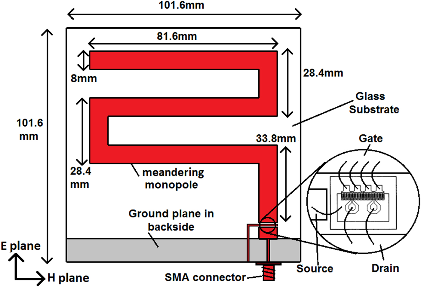
Fig. 1. Geometry and dimensions of the meandering active antenna.
The MESFET transistor is used in common source configuration as an amplifier. The source is grounded through a parasitic printed line. The grid is linked to the monopole and the drain to the output of the antenna. The bias circuit is detailed in Fig. 2. C is a decoupling capacitor of 100 nF;  $L1$ and
  $L2$ are choke inductors of 10 μH. The transistor is polarized under a drain voltage
  $V_{DS}=$ 3 V and a drain current
  $I_{DS}=$ 20 mA. The transistor has a micrometric size (outside dimensions: 380 μm × 480 μm), thereby a low visual impact on the global transparency of the antenna.
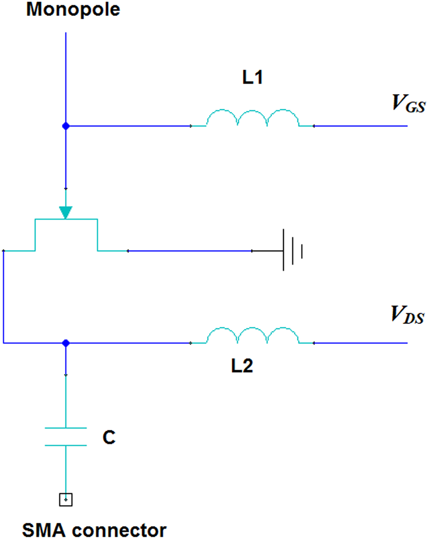
Fig. 2. Detail of the bias circuit.
The transparent and conducting layer used to fabricate the printed FM antenna is a home-made micrometric mesh silver film. The pitch p and metal strip width s are selected to get a high level of optical transparency (equation 1), and to be no-visible to the naked eye. For this, the pitch of the mesh needs to be smaller than the human visual acuity:  $\theta _{min} \approx 4.9\times 10^{-4}$ rad [Reference Charman13] at the viewing distance d (equation 2). Therefore p has to be smaller than 400 μm at
  $d=$ 0.75 m.
 $$T(\% ) = \left( {\displaystyle{{\,p - s} \over p}} \right)^2 \times T_{sub},$$
 $$p \lt d \times \theta _{min}.$$
 The selected parameters are  $ p \approx 360 \mu {\rm m} $ and s = 10 μm, given a theoretical optical transparency
  $T=$ 87% (including Fresnel loss). Moreover, the sheet resistance
  $R_s'$ of the mesh metal layer is computed from equation 3 as follows:
 $$R_s^{\rm ^{\prime}} = \displaystyle{\,p \over s} \times R_s = \displaystyle{\,p \over s} \times \displaystyle{\rho \over t},$$
where  $R_s$ is the sheet resistance of the metal layer before the mesh processing, ρ is the resistivity (
 $\rho = 1.64\times 10^{-8}\Omega $.m for silver [Reference Haynes14]) and t is the thickness of the metal layer (
 $t =$ 6 μm). With the selected parameters,
  $R_s'=$ 0.10 Ω/sq which is significantly lower than that of the available commercial solution AgHT-4 (4 Ω/sq [Reference Azini, Kamarudin and Jusoh15]) or from an OTC/metal multilayer solution (4.99 Ω/sq [Reference Hong, Kang and Jung7]).
The mesh silver film was fabricated with the process fully described elsewhere [Reference Hautcoeur, Castel, Colombel, Benzerga, Himdi, Legeay and Motta-Cruz12]. A continuous silver film (6 μm-thick) and a titanium underlayer (5 nm-thick) are both deposited onto 1737 Corning glass substrate by RF magnetron sputtering technique at room temperature. The titanium underlayer is used here only to ensure the strong adhesion of the silver overlayer onto the glass substrate. Subsequently, a standard photolithographic wet etching process is used to fabricate the transparent sample from a mesh photomask. Stripping of the photoresist leaves the antenna pattern with a periodic array of apertures in the metal coating (Fig. 3). A detail of the mesh pattern is shown in Fig. 4.

Fig. 3. Picture of the transparent FM antenna placed above the laboratory logo.

Fig. 4. Optical microscopy observation of the mesh pattern.
The thickness of the silver layer remains small ( $t =$ 6 μm) compared with the skin thickness value
  $\delta =$ 6.4 μm (equation 4) at the operating frequency f (~100 MHz):
 $$\delta = \sqrt {\displaystyle{\rho \over {\mu _0\pi f}}} ,$$
 where  $\mu _0$ is the permeability of the free space.
To avoid the loss due to skin depth effect, it is recommended to use a metal thickness greater than 3 $\times \delta \approx $ 19 μm. Nevertheless, the deposition technique used here does not allow access such a thickness, explaining the choice of a 6 μm-thick silver film. It is worth noting that the skin depth effect is also present in the width of the strips due to their narrowness (
 $s =$ 10 μm). This constraint did not appear in the previous studies based on the transparent micrometric mesh antennas due to the higher operating frequencies (865 MHz [Reference Hautcoeur, Colombel, Castel, Himdi and Motta Cruz16], 2 GHz [Reference Hautcoeur, Castel, Colombel, Himdi and Motta-Cruz17], 10 GHz [Reference Martin, Castel, Lafond and Himdi5], 24 GHz [Reference Dao, Braun and Geck18], 60 GHz [Reference Hautcoeur, Talbi and Hettak19]). It would be possible to solve this deficiency by doubling the strip width (
 $s =$ 20 μm) but at the expense of the sample optical transparency (theoretical variation from 87 to 82%). In the present study, we have favored the high-optical transparency level of the printed FM antenna.
The optical transparency of the antenna was measured by a UV/visible spectrophotometer. The measured transparency remains constant ( $T= $ 87%) over the entire visible light spectrum (Fig. 5), in complete agreement with the theoretical value (
 $T= $ 87%). No interference fringe is observed on the curve, as it can be noticed with OTC single layers [Reference Colombel, Castel, Himdi, Legeay, Vigneron and Motta Cruz8] or OTC/metal multilayers [Reference Hong, Kang and Jung7]. The sheet resistance was measured with a standard four-probe setup with a current source and a high-impedance microvoltmeter. The measured value is
  $R_s'=$ 0.22 Ω/sq, higher than expected (
 $R_s'=$ 0.10 Ω/sq, see equation 3). The higher experimental value may be due to the small width of the antenna ribbon (8 mm, see Fig. 1) which restricts the roll-out of the current during the measurement, and thereby artificially increases
  $R_s'$ value.
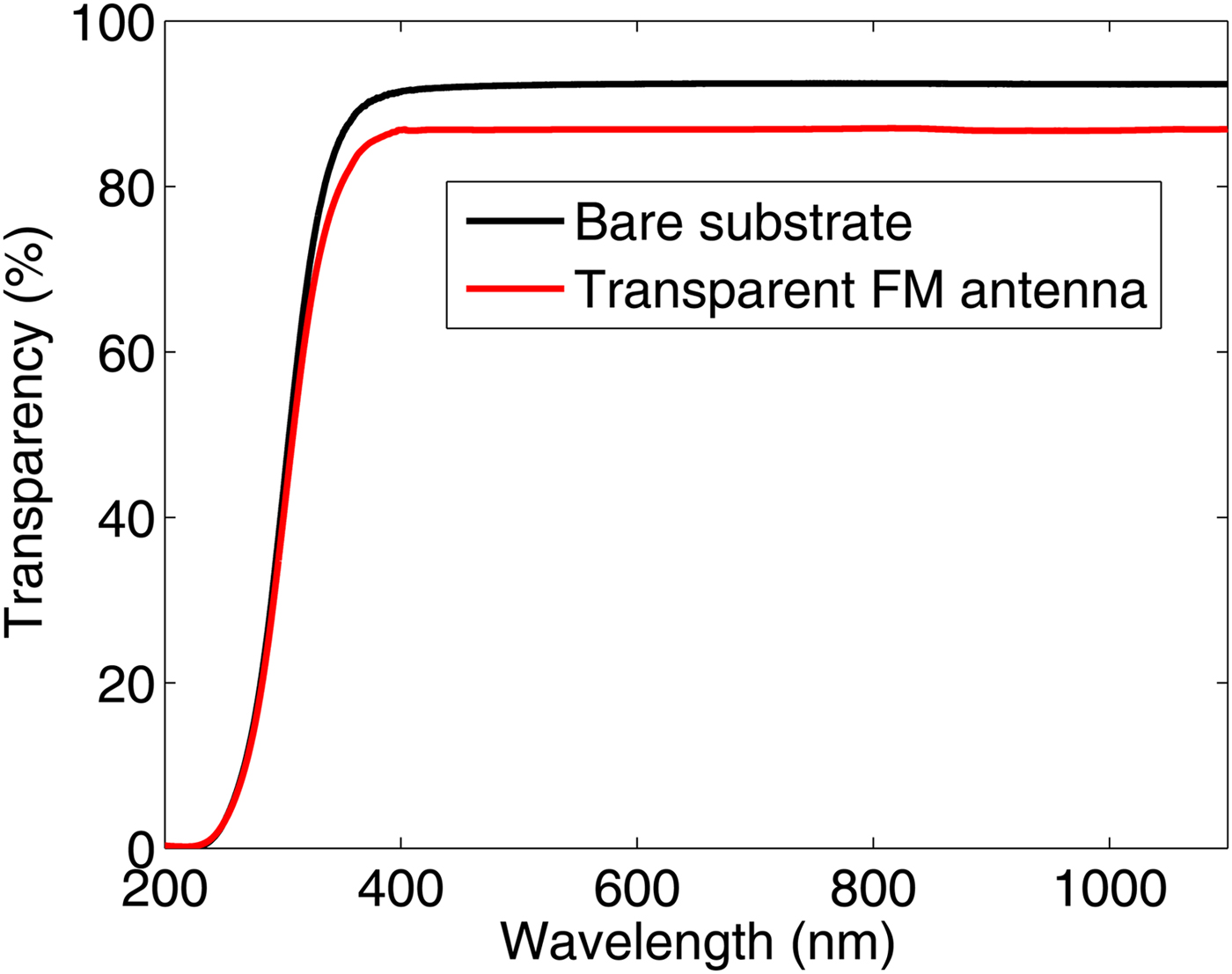
Fig. 5. Measured optical transparency.
Numerical results and radiofrequency measurements
A model of the MESFET transistor was used with ADS software (Fig. 6). S parameters of the transistor (Fig. 7) were thus retrieved under biasing values indicated in the section “Antenna design and fabrication” ( $V_{DS}=$ 3 V and
  $I_{DS}=$ 20 mA).

Fig. 6. ADS model of the MESFET transistor.
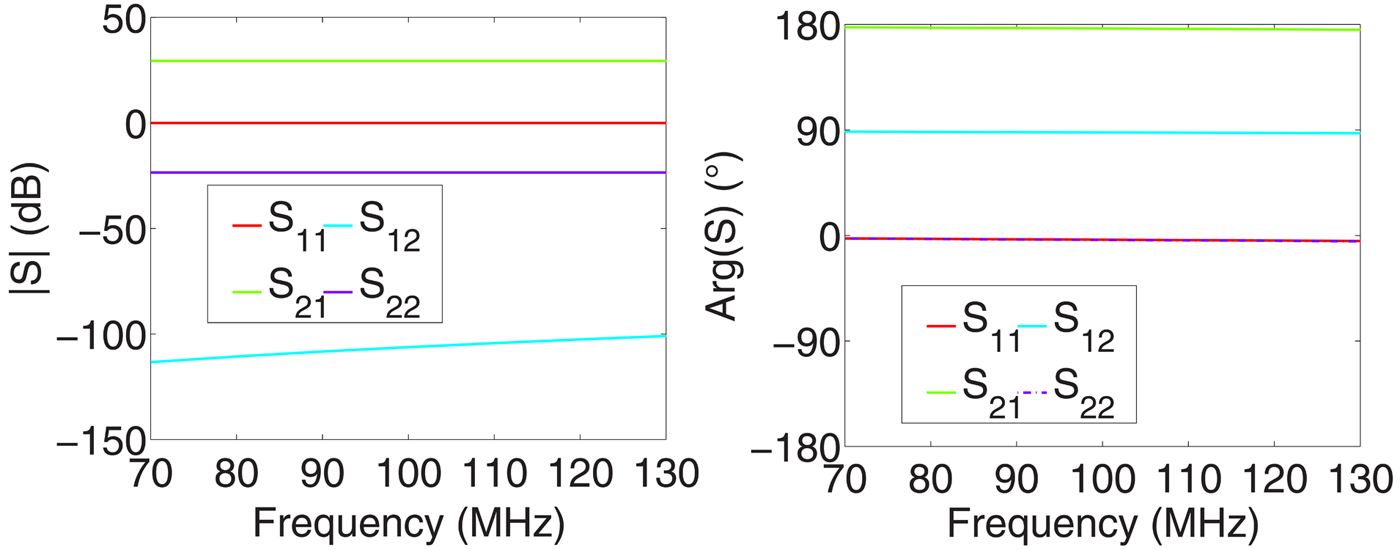
Fig. 7. S parameters of the MESFET transistor (port 1: gate-source and port 2: drain-source).
Due to the unilaterally of the transistor, the antenna only operates in reception. To evaluate its input impedance, an electromagnetic calculation was combined with the electrical model of the transistor. The numerical simulations were performed with CST Microwave Studio®. The simulated FM antenna was not designed with the mesh silver layer (due to the very high numerical capabilities required) but with a continuous 6 μm-thick silver layer printed onto the 1737 Corning glass substrate. Figure 8 presents the simulated reflection and transmission coefficients magnitudes of the FM receiving antenna. Its dimensions have been optimized to set the resonance frequency close to 100 MHz. The reflection coefficient is above −10 dB over the entire FM radio band (88 − 108 MHz) through the MESFET transistor direct matching. Indeed, the antenna input impedance without the transistor is equal to 1−j251 Ω at 100 MHz. Due to the unilaterally of the transistor, the input impedance of the active antenna is equal to the output impedance of the transistor itself (94−j4 Ω at 100 MHz). Therefore, the monopole antenna does not require any additional impedance matching adapter, contributing to its miniaturization. It is worth noting that the MESFET transistor also amplifies the received FM signal with low power consumption.
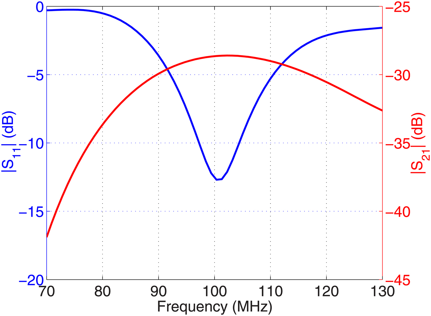
Fig. 8. Reflection  $\vert S_{11}\vert $ and transmission
  $\vert S_{21}\vert$ coefficients computed with CST software.
To assess the gain of the antenna, the Link Budget Method described in [Reference An, Nauwelaers, de Capelle and Bosisio20] is used with the Friis formula expressed as follows:
 $$G_{ant(dB)} = S_{21(dB)} - 20\log \left( {\displaystyle{\lambda \over {4\pi D}}} \right) - G_{Tr(dB)},$$
where  $G_{ant(dB)}$ is the gain of the FM receiving antenna,
  $S_{21(dB)}$ is the transmission coefficient,
  $G_{Tr(dB)}$ is the gain of the transmitting antenna, D is the distance between the transmitting and receiving antennas in far-field conditions and λ is the working wavelength. The transmission coefficient simulated at 100 MHz with
  $D=$ 1.7 m and
  $G_{Tr}=$ 2.2 dBi is equal to
  $\vert S_{21}\vert=-$28.7 dB, yielding a FM antenna gain
  $G_{ant}=-$13.8 dBi. This low value is due to the small electrical dimension of the FM antenna (
 $\lambda _0$/21 at 100 MHz) and the skin depth effect. Nevertheless, this gain is valuable for a FM radio reception application and is higher than that reported in [Reference Taachouche, Colombel and Himdi4] (−19.6 dBi) because of its relative larger size (
 $\lambda _0$/21 in our case against
  $\lambda _0$/175 in [Reference Taachouche, Colombel and Himdi4]).
The FM antenna operating in the receiving mode, the radiation pattern was simulated without the active MESFET transistor (Fig. 9). It is similar to that of a dipole antenna: omnidirectional in the H-plane and a 90 $^\circ $ half power beam width in the E-plane. As expected, the cross-polarization value remains lower than −20 dB.
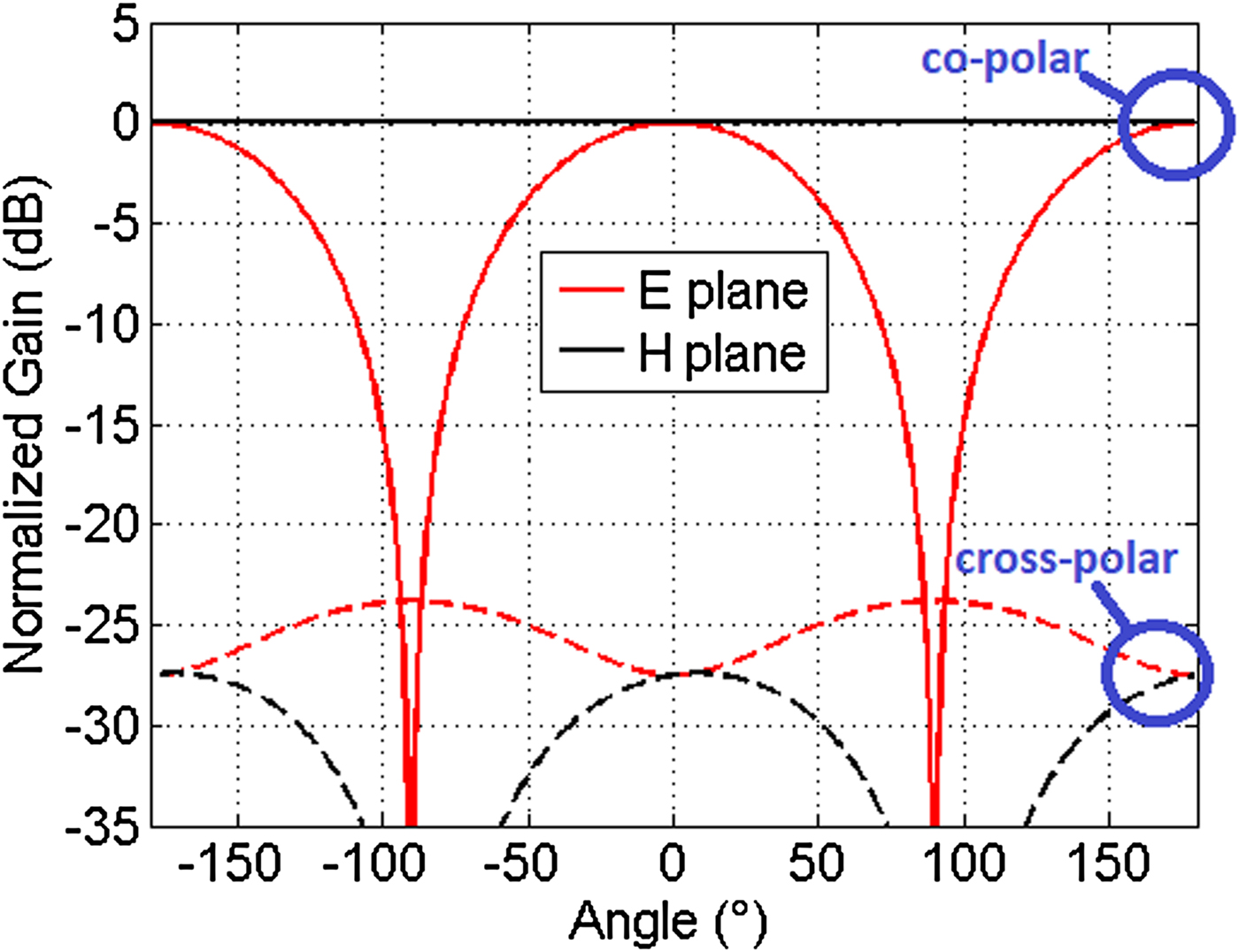
Fig. 9. Normalized simulated radiation pattern of the passive antenna (without the MESFET transistor).
The RSSI (Fig. 10) and the SNR (Fig. 11) were measured and compared with those of a commercial monopole antenna (a quarter-wave wire antenna). The average difference in RSSI between the transparent FM and the commercial antennas is 8.8 dB, and only 4.4 dB for the SNR parameter. These ensure a valuable received signal quality to listen to the FM radio without interferences (hiss, crackle, and fade). From the RSSI measurement, it is possible to assess the gain of the transparent FM antenna from the gain of the commercial monopole antenna (1 dBi). The transparent FM antenna gain is therefore estimated at about −8 dBi, value higher than that obtained from the simulated result (−13.8 dBi). We assign this result to the measurement environment (multipath reception of the FM signal). It is also possible to compare the performance of the present antenna to another electrically small ones (Table 2). It is worth noting that the FM antennas available in the literature are not optically transparent, thereby strengthening our technology.

Fig. 10. Measured RSSI.
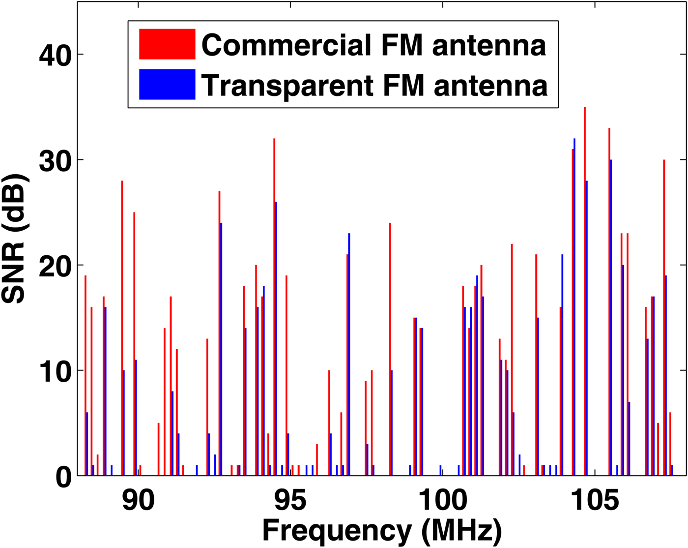
Fig. 11. Measured SNR.
Table 2. Dimensions and performance of different electrically small FM antennas

Conclusion
An optically transparent FM antenna with a small electrical dimension ( $\lambda _0$/21) has been designed, fabricated, and characterized. This antenna exhibits a high level of transparency (T = 87%) over the entire visible light spectrum with a low-visual impact, unlike the available see-through FM antennas “http://www.max-signal.com/product/12/monarch-50-hdtv-indoor-antenna-transparent”. The sheet resistance value remains lower than 0.22 Ω/sq. A gain close to −8 dBi at 100 MHz associated with radio performance (RSSI and SNR) similar to that of a commercial quarter-wave wire antenna have been obtained. These results allow us to consider its further implementation onto automotive glazing for a high-quality FM radio reception.
Acknowledgments
This work was supported by the European Union through the European Regional Development Fund (ERDF), the Ministry of Higher Education and Research, the Région Bretagne, the Département des Côtes d'Armor and Saint-Brieuc Armor Agglomération, through the CPER Projects 2015-2020 MATECOM and SOPHIE / STIC & Ondes.
 Alexis Martin received his M.S. degree in Electronics and Telecommunication from University of Rennes 1, Rennes, France in 2014. Since 2014, he has been a Ph.D. student at the Institute of Electronics and Telecommunications of Rennes (IETR), University of Rennes 1, France. He is working on optically transparent and active antennas. He is author and co-author of three international papers, and nine conference presentations.
 Xavier Castel received the Ph.D. degree in Material Science from the University of Rennes 1, Rennes, in 1997. He is an Associate Professor with the Technological Institute of Saint-Brieuc, University of Rennes 1, Saint-Brieuc, France, since 1999 and a Researcher with the Institute of Electronics and Telecommunications of Rennes, University of Rennes 1. He is Cohead of the “Multifunctional Materials” Team in the “Antennas & Microwave Devices” Department. He is the author and coauthor of ˜50 international papers, more than 180 conference presentations, and holds 12 patents. His main research interests include the elaboration of advanced materials (transparent materials and transparent conducting oxides; superconductors; semiconductors, composite materials) for microwave applications, their physical-chemical characterizations (electrical, optical, structural, microstructural, morphological properties, etc.), and the fabrication of the related microwave devices (by photolithographic technique, wet-etching process, lift-off process, and laser micro-etching).
 Mohamed Himdi received the Ph.D. degree in signal processing and telecommunications from the University of Rennes 1, France in 1990. Since 2003, he has been a Professor with the University of Rennes 1, and the Head of the High Frequency and Antenna Department until 2013, of IETR. He has authored or coauthored 107 journal papers and over 240 papers in conference proceedings. He has also coauthored nine book chapters. He holds 35 patents. His research activities concern passive and active millimeter-wave antennas. His research also include development of new architectures of antenna arrays, and new three-dimensional (3D) antenna technologies. He was Laureat of the 2d National Competition for the Creation of Enterprises in Innovative Technologies in 2000 (Ministry of Industry and Education). In March 2015 he received the JEC-AWARD at Paris on Pure composite material antenna embedded into a motorhome roof for the Digital Terrestrial Television reception.


