Introduction
Long et al. first proposed the use of dielectric resonator (DR) as a radiator in the early 80s, which was popularly named later as the dielectric resonator antenna (DRA) [Reference Long, Mcallister and Shen1]. DRA is similar to the microstrip patch antenna in many aspects, e.g., it is a low-profile structure (based on the dielectric constant) and is compatible with almost all standard feed mechanisms [Reference Petosa and Ittipiboon2, Reference Guha and Kumar5]. But a DRA offers unique features such as higher radiation efficiency, wider impedance bandwidth, and the ability to produce different types of radiation patterns through mode selection [Reference Petosa and Ittipiboon2–Reference Guha and Kumar5]. For a given feed mechanism used with a DRA, the impedance matching is often achieved by adjusting the feed position relative to the center of the DRA and tracking the minimum of the magnitude of the input reflection coefficient (|Γ in|min). Once the feed point is located, the DRA is attached on the feed structure for detailed measurements. This traditional approach may however result in a sub-optimum design as the impedance matching is the only criterion that decides the feed point. In this paper, it is shown that for a DRA, there exists multiple feed points with good impedance matching (|Γ in|min ≪ −10 dB) but with dissimilar radiation properties. Then the importance of feed-point selection for a DRA is discussed for the first time by taking three common feed mechanisms – the microstrip line feed, the microstrip slot feed, and the coaxial probe feed as examples.
The feed mechanisms
Standard feed mechanisms are realized either as single-ended feeds or differential feeds. Single-ended feeds are simpler in construction and operation [Reference Petosa and Ittipiboon2, Reference Guha and Kumar5], while differential feeds, at the cost of tighter amplitude and phase balance of the feed currents, result in lower spurious (cross-polar) radiation [Reference Tang, Chen, Zhan, Yang, Zhou and Li6, Reference Li and Leung7]. In either type, it is important to know in advance the field distribution of the particular DRA mode to be excited. It is known that the hybrid modes of a DRA radiate as multi-poles [Reference Mongia and Bhartia8]. The dominant broadside mode of an isolated cylindrical DRA designated as the HEM11δ (approximated as TM110) mode radiates mostly like a horizontal magnetic dipole [Reference Mongia and Bhartia8]. The feed mechanism designed for exciting the HEM11δ mode is required to couple maximum energy only to the magnetic dipole and minimum energy to the lower and higher order multi-poles. The relative strengths of constituent multi-pole components of the mode will thus depend on the feed point for a given feed mechanism. Choice of the wrong feed point of the DRA will thus result in a reduction of the purity of the desired mode, hence deterioration of the DRA performance. Major performance parameters that are affected in this way are the symmetry of the radiation pattern and the level of the cross-polarized radiation. In order to analyze the above effects, a microstrip line, a microstrip slot, and a coaxial probe, individually coupled to the same DR, are modeled using Finite Element Method (FEM)-based EM simulator ANSYS HFSS. The design parameters of the DR are shown in Table 1. The modeling and simulation are discussed in the following sub-sections.
Table 1. Design parameters for the DR and the feed mechanisms
Microstrip line feed
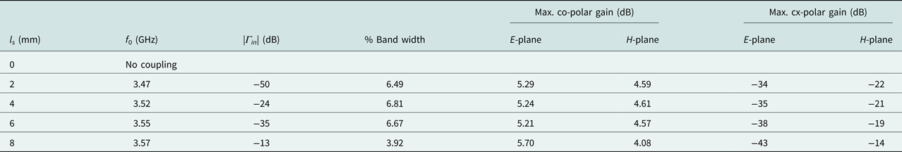
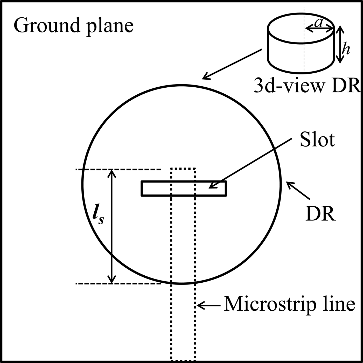
Microstrip line offers simplicity in the design, fabrication, and impedance matching and can be used for exciting the HEM11δ mode of a cylindrical DRA [Reference Rashidian, Tayfeh Aligodarz, Shafai and Klymyshyn9]. A 50 Ω microstrip line terminated in an open circuit is designed using a copper-coated dielectric substrate to which the DRA is proximity coupled. Microstrip line design parameters for 50 Ω are shown in Table 1. Symmetric positioning of the DR with respect to the open end of the line is very important for setting the polarization of the HEM11δ mode in the direction of the microstrip line. The ε r of the DR being high (ε r = 24) eases the impedance matching to the 50 Ω feed [Reference Kranenburg and Long10]. The schematic representation of the microstrip-fed DRA is shown in Fig. 1. The DRA is placed on the top of the line so that the open end extends under the DRA by a length l s, which decides the feed point. The feed parameter l s is varied from 0 to 8 mm, and the magnitude of the input reflection coefficient |Γ in| is recorded. The antenna characteristics are then extracted at the minimum |Γ in| frequency (f 0) and are shown in Table 2. Maximum gains from the radiation patterns in the two principal planes (E-plane and H-plane) are recorded in the ±90° range about the boresight.
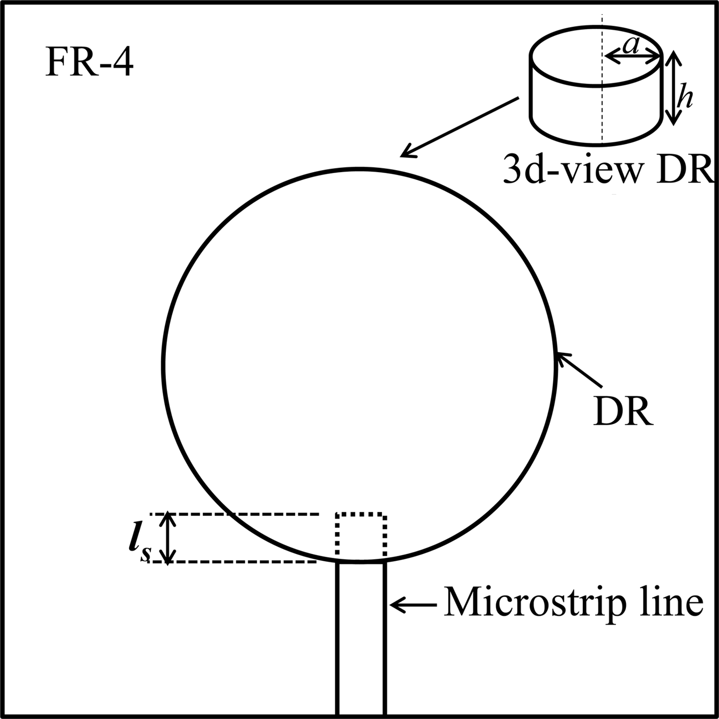
Fig. 1. Schematic representation of microstrip line-fed DRA.
Table 2. Characteristics of microstrip line-fed DRA, for various feed points (l s in Fig. 1)

Microstrip slot feed
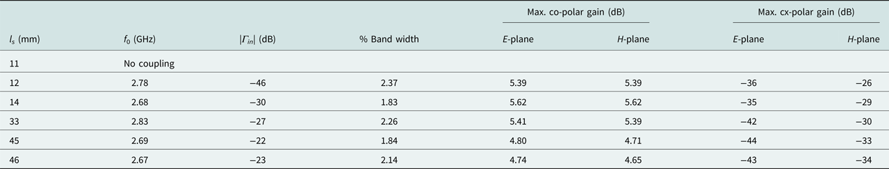
The DR is placed directly on top of the slot made on the ground plane with its center coinciding with the center of the slot [Reference Kishk, Ittipiboon, Antar and Cuhaci11]. The 50 Ω microstrip is running on the backside of the substrate that couples to the DR through the slot, as shown in Fig. 2. Detailed design parameters of the slot feed are shown in Table 1. The length l s of the microstrip open end as shown in Fig. 2 is adjusted to achieve impedance matching. Table 3 shows the antenna properties for different l s for the slot-fed DRA.

Fig. 2. Schematic representation of microstrip slot-fed DRA.
Table 3. Characteristics for microstrip slot-fed DRA, for various feed points (l s in Fig. 2)
Coaxial probe feed
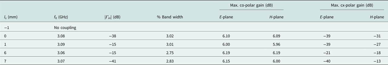
The schematic representation of the coaxial probe-fed DRA is shown is Fig. 3, which is based on the design parameters given in Table 1. The DR is mounted directly on top of the metallic ground plane, through which the probe of a 50 Ω coaxial line is extended upward. The probe length above the ground plane is chosen in order to achieve the best impedance matching for any feed point decided by length l s. Antenna characteristics for this arrangement are tabulated in Table 4.
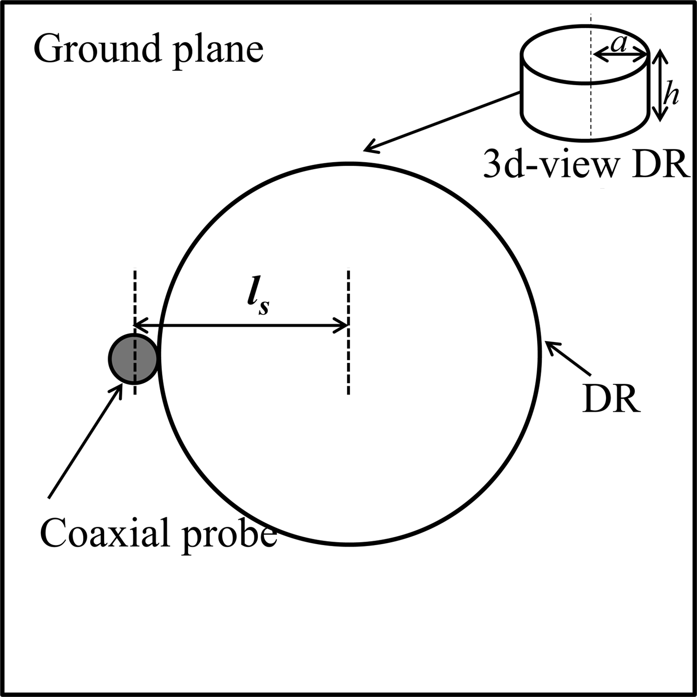
Fig. 3. Schematic representation of coaxial probe-fed DRA.
Table 4. Characteristics of coaxial probe-fed DRA, for various feed points (l s in Fig. 3)

Discussion of simulation results
Effect of the feed point on the DRA performance
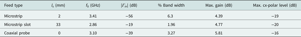
For the microstrip-fed DRA, as shown in Table 2, an impedance matching with |Γ in| < −10 dB is achieved when l s > 0 mm, i.e. the strip end overlaps with the DR. As l s increases, the resonant frequency keeps increasing at smaller steps, while the percentage bandwidth first increases then decreases. The reflection coefficient also varies cyclically with the minimum value at l s = 2 mm and the maximum value at l s = 8 mm. Peak gains in the E-plane and the H-plane deviate from each other as l s is increased, implying an asymmetry of the radiation pattern. The cross-polarized gain in the H-plane also increases with l s in a fashion similar to that observed with the pattern asymmetry. The lowest impedance matching of |Γ in| of −13 dB, the highest level of pattern asymmetry of 1.62 dB, and the highest cross-polar gain of −14 dB are achieved when the tip of the microstrip is nearer to the center of the DR, i.e., at l s = 8 mm. Thus, it can be concluded that geometrically asymmetric feeds such as the microstrip line excites the HEM11δ mode with less modal purity, implying the presence of higher levels of higher order multi-polar components.
As shown in Table 3, for the microstrip slot-fed DRA, at feed point l s < 12 mm, the strip does not completely cross the slot, hence results in insufficient coupling to the DR. Owing to the high inductance of the narrow slot, the tolerances of a slot-fed DRA for impedance matching are much tighter than that of the microstrip feed. The resonant frequency and bandwidth follow cyclic behavior with l s. It can be noted that for all values of l s, the radiation pattern is nearly symmetric with reduced cross-polarized radiation in the H-plane. It can also be noted from Table 3 that as l s gets higher, both the impedance matching and the cross-polarization level get lower, a trend contrary to that observed in the case of the microstrip-fed DRA.
In the case of the coaxial probe-fed DRA, feed point l s < 0 mm does not cause any physical contact between the probe and the DRA, hence no impedance matching is achieved. At l s = 0 mm, excellent impedance matching of |Γ in| = −38 dB and the least cross-polarization level of −31 dB are observed. When the probe location is closer to the center of the DR, i.e., l s = 7 mm, the H-plane cross-polarization reaches its maximum of −13 dB. It is also observed that the frequency sensitivity of the probe-fed DRA is the least among the three.
Performance comparison among the feeds
Analysis of the results provided in Tables 2–4 indicates that performance of a given DRA excited in the HEM11δ mode depends on the particular feed mechanism also for a given DR geometry and material properties. For the microstrip slot and the coaxial probe feeds, the DRA is placed directly on the metallic ground plane, hence by image theory, effective DR height is double the actual height (~2h). This is however not true for a microstrip feed as the DR is separated from the ground plane by the substrate. Hence the effective DR height does not get doubled and the resonant frequency is higher than that for the other two feeds. The presence of the dielectric spacer (substrate) between the DR and the ground also reduces the cavity effect, hence results a lower Q-factor and a wider bandwidth of all the three feeds. It can also be seen in Tables 2–4 that the bandwidth of the microstrip-fed DRA is at least twice that of the other two feeds. Presence of finite substrate losses (tanδ = 0.02) however causes the gain of the microstrip-fed DRA to be the lowest of the three feeds. For the slot feed, the effective feed-point inductance is much higher than that for the other two feeds, which causes the resonant frequency of the slot-coupled DRA to be the lowest of the three. The radiation pattern of the slot-fed DRA is highly symmetric, indicated by equal boresight gains in E- and H-planes. A symmetric radiation pattern also correlates with lower cross-polarized radiation in the H-plane as indicated in the tables. Thus, the slot feed is the best feed in terms of reduced excitation of unwanted multi-polar components.
Selection of optimum feed point
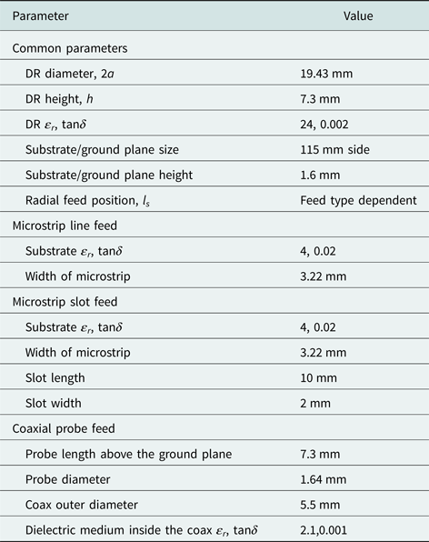
Based on the discussions made in the above section, it can be inferred that for both the microstrip and the probe feeds (Tables 2 and 4, respectively) the feed point (l s) is preferred to be as close to the edge of the DRA as possible, for the desired mode to be excited with lesser spurious (multi-polar) components. For the slot feed (Table 3), for every value of l s, the mode symmetry is maintained, indicating very less spurious components in the mode. For any feed mechanism, the E-plane cross-polar gain is below approximately −30 dB for most of the feed points, and the H-plane co-polar pattern is more or less symmetric. Thus, for the microstrip feed, the slot feed and the coaxial feed, l s = 2, 33, and 0 mm, respectively, are chosen as optimum feed points. Figures 4 and 5 show the magnitude of the reflection coefficient and the radiation patterns, respectively, for the best feed design that compromises among the impedance matching, bandwidth, pattern symmetry, and cross-polar levels. As indicated in Fig. 5, the microstrip-fed DRA and the coaxial probe-fed DRA have more or less similar H-plane cross-polar distributions, which maximize within ±90° about the boresight with a null at 0°. On the other hand, for the slot-fed DRA, maximum H-plane cross-polar radiation occurs within ±90° about the back lob direction. For the slot-fed DRA, presence of the three nulls in the H-plane cross-polar pattern within ±90° to the boresight imply the absence of those multi-polar components that are present in the microstrip- and the coaxial-fed DRAs.

Fig. 4. Reflection coefficients of the DRA with different feeds (microstrip l s = 2 mm microstrip slot l s = 33 mm, coaxial probe l s = 0 mm).
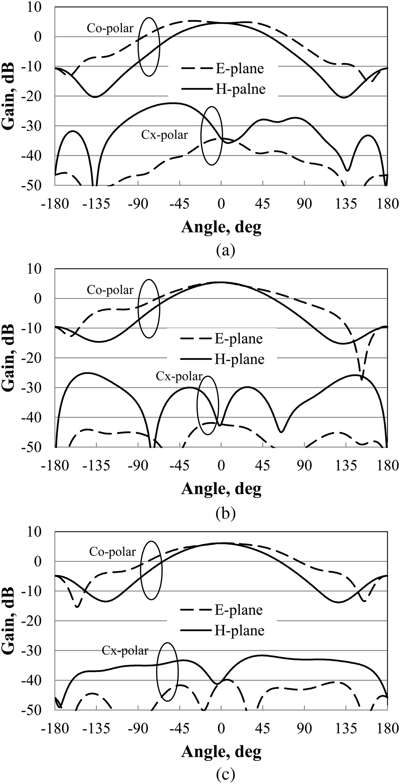
Fig. 5. Simulated radiation pattern of the DRA with different feeds (microstrip l s = 2 mm, microstrip slot l s = 33 mm, coaxial probe, l s = 0 mm). (a) Microstrip-fed DRA, (b) microstrip slot-fed DRA, (c) coaxial probe-fed DRA.
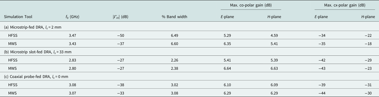
Performance of the optimum design for each feed type is cross-verified with CST Microwave Studio (MWS) which is based on Finite Integration Technique (FIT). Comparison between CST and HFSS generated results is given in Table 5, which show decent agreement.
Table 5. Comparison of the DRA performance for the three different feed mechanisms using ANSYS HFSS and CST Microwave Studio (MWS)

Prototypes and measurement
The microstrip line and the microstrip slot feeds are fabricated using FR-4 substrate, while the coaxial probe feed is fabricated using the same substrate (double-sided PCB) with the top and the bottom metallizations soldered together along the edges. This is done for having a light-weighted antenna to help mounting and alignment, which otherwise is difficult with a thick metal sheet. Photographs of the fabricated feed mechanisms are shown in Fig. 6.
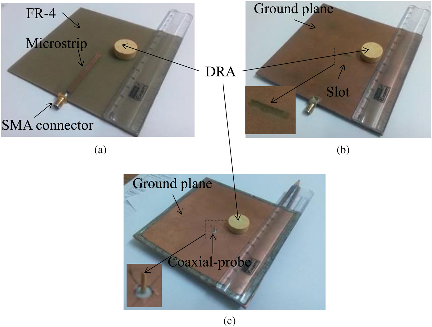
Fig. 6. Fabricated feed mechanisms. (a) Microstrip, (b) microstrip slot, (c) coaxial probe.
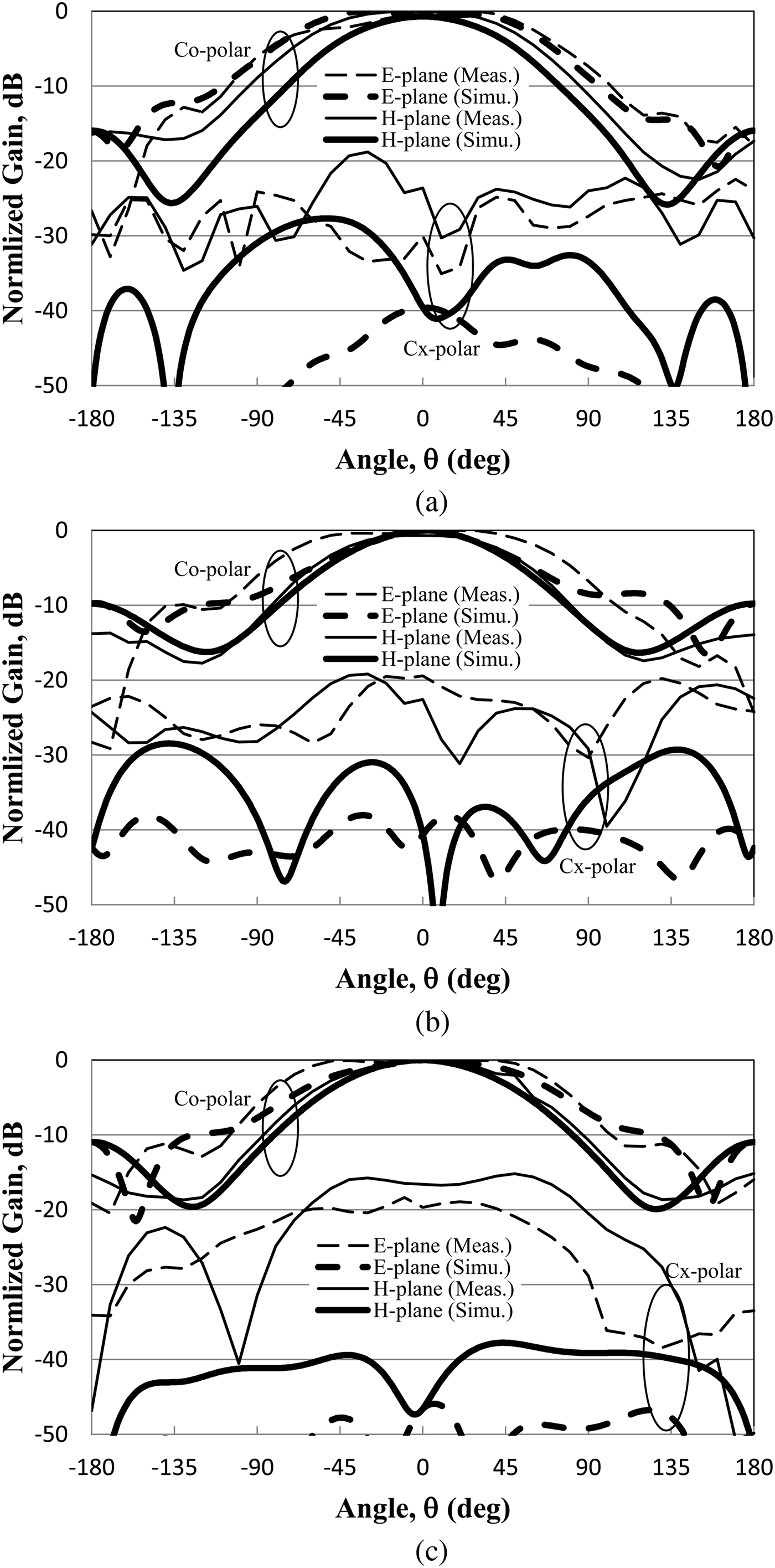
Measurements of the DRAs are carried out in an anechoic chamber environment, using Keysight Technologies N9928A vector network analyzer. Measured reflection coefficients for the three feed mechanisms are shown in Fig. 7 and the radiation patterns in Fig. 8, both in comparison with the respective simulated results. Important characteristics extracted from Figs 7 and 8 are shown in Table 6. As shown, measured resonant frequencies and bandwidths closely agree with the simulated results. Although the absolute values differ between simulation and measurement, relative variation from feed to feed follows the same trend as observed in simulations. Impedance matching and bandwidth are the highest with the microstrip feed, while the same is the lowest with the slot feed. Similarly, the highest gain is for the probe-fed DRA and the lowest for the microstrip-fed DRA. Pattern symmetry is well maintained by both the microstrip slot and the coaxial probe feeds over the upper hemisphere, as observed in simulations. However, in contrary to what is seen in simulation, the measured peak cross-polar levels (normalized with peak co-polar level) do not show much variation from feed to feed. This is because, accurate measurement of weak cross-polar radiation is difficult and is highly sensitive to alignment and other experimental errors [Reference Sabouni and Kishk12]. Present measurements involved a good amount of manual positioning and alignment of the DRA, hence the mismatch in the measured cross-polar results is expected.
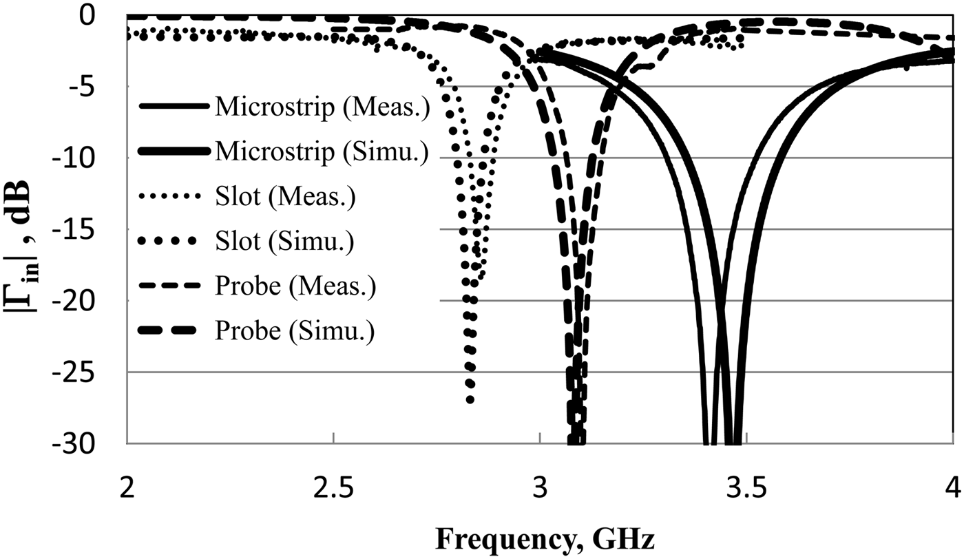
Fig. 7. Measured versus simulated reflection coefficients of the DRA with different feeds (microstrip l s = 2 mm, microstrip slot l s = 33 mm, coaxial probe l s = 0 mm).

Fig. 8. Measured versus simulated radiation patterns (normalized) of the DRA with different feeds (microstrip l s = 2 mm, microstrip slot l s = 33 mm, coaxial probe l s = 0 mm). (a) Microstrip-fed DRA, (b) microstrip slot-fed DRA, (c) coaxial probe-fed DRA.
Table 6. Comparison of the measured DRA performance for different feed mechanisms

Conclusion
The paper presented an investigation on the selection of the feed point of a cylindrical DRA based on the impedance and the radiation performances. Three standard feed mechanisms were investigated using HFSS simulator in order to understand the variation in the DRA performance with the feed point for a given feed type and also among the feeds themselves. Higher pattern symmetry and lower H-plane cross-polarization level were achieved with both the slot feed and the coaxial feed, while the highest percentage bandwidth was the main attraction of the microstrip feed. The highest gain was offered by the coaxial-fed DRA. Optimum feed designs were cross-verified in CST MWS that showed good agreement with the HFSS results. Prototypes of the three feed mechanisms were fabricated and measurements were carried out for the optimum feed points. All except the cross-polarization levels were in good agreement with numerical predictions. This study will help the DRA community in being more attentive while fabricating the DRA, because positioning errors can shift the optimum feed point and deteriorate the antenna performance as discussed in this paper. It should be mentioned that all these analysis and comparisons were performed for a fixed ground plane (substrate) size. Proper selection of the ground plane size will further improve the DRA performance through edge diffraction effects.
Acknowledgements
This work was supported by the Department of Science and Technology (DST), India, through the FIST program under Grant Ref: SR/FST/ETI-346/2013. Authors would like to thank Mr. Mahesh Chandra Saini for his assistance in the radiation pattern measurement at the parent institute.
 Anuj Kumar Ojha received his M.Tech. degree in digital communication from Rajasthan Technical University (RTU), Kota Rajasthan in 2013. Later he joined the MEMS group at CSIR-CEERI Pilani, Rajasthan, as the project fellow, where he worked on the development of silicon-based MEMS pizoresistive pressure sensors for various applications. He has published journal/conference papers on various aspects of MEMS sensors. Presently, he is pursuing Ph.D. degree at the Department of Electrical and Electronics Engineering, Birla Institute of Technology and Science, BITS Pilani (Pilani campus), Rajasthan, India. His research interests include dielectric resonator antennas, higher order mode antennas, and sensors.
 A.V. Praveen Kumar received his Ph.D. degree in microwave electronics from the Department of Electronics, Cochin University of Science and Technology (CUSAT), Kerala in 2009. His thesis was on the fabrication, characterization, and development of dielectric resonators and its application in wideband dielectric resonator antennas. He joined the Engineering department, Lancaster University, UK, as a post doctoral fellow where he worked on the development of radiofrequency cavities for particle accelerators. His major research interest is in RF and microwave engineering, which includes antennas, cavity resonators, particle accelerators, and material characterization techniques. He has published several international journal/conference papers on various aspects of RF engineering. Presently, he is working as an Assistant Professor in the Department of Electrical and Electronics Engineering, Birla Institute of Technology and Science, BITS Pilani (Pilani campus), Rajasthan, India.