


I. INTRODUCTION
In 2007, Professor Marin Soljacic of Massachusetts Institute of Technology (MIT) used the magnetic coupling resonance principle to illuminate a 60 watt bulb at a distance of 2 m, and the transfer efficiency reached 40% [Reference Kurs, Karalis, Moffatt, Joannopoulos, Fisher and Soljacic1]. Compared with other wireless power transfer technologies, the magnetic coupling resonance wireless power transfer technology has a medium transfer distance, emits no radiation to the environment, has a high transfer efficiency, and is also closely linked with daily life. It has therefore attracted the attention of many researchers and businessmen and led to a boom in research of magnetic coupling resonance wireless power transfer technology.
Currently, some colleges and research institutes have achieved many meaningful results in terms of magnetic coupling resonance wireless power transfer systems in the areas of principle elaboration, transfer characteristics, new materials, and practical applications. In order to increase the transfer distance and transfer efficiency, the researchers in papers [Reference Imura2, Reference Kim, Son, Kim and Park3] introduced a repeater into the magnetic coupling resonance wireless power transfer system; devices such as power amplifiers, rectifiers, and dc–dc converters have also been introduced [Reference Moriwaki, Imura and Hori4]. The researchers in paper [Reference Wang, Teo, Nishino, Yerazunis, Barnwell and Zhang5] applied metamaterials to improve the transfer efficiency of wireless power transfer systems, but the energy losses, volume size, fabrication, and the cost of metamaterials still needs to be carefully considered. The work in paper [Reference Kim, Chung and Kang6] reduces the coil losses and increases the transmission distance by utilizing a superconductor, which is very expensive. Paper [Reference Kar, Nayak and Bhuyan7] investigates the effects of proximal metallic material objects in the vicinity of the receiving coil, which helps provide future guidelines for magnetic coupling wireless power transfer systems in the presence of metallic objects. Numerous applications for magnetic coupling resonance wireless power transfer have been proposed, such as charging electric vehicles [Reference Ko and Jang8, Reference Shin, Shin and Kim9] and personal electronics [Reference Kim, Son and Kim10]. The analyses of magnetic coupling resonance wireless energy transfer systems mainly use the equivalent circuit theory [Reference Cannon, Hoburg and Stancil11–Reference Lower, Fragar and Depcynzksi13] and the coupled-mode theory [Reference Karalis, Joannopoulos and Soljačić14]. The coupled-mode theory analyzes the magnetic resonance wireless transmission system directly from an energy viewpoint and does not involve specific parameters, and so there are less actual applications. The equivalent circuit theory directly makes the resonant coil equivalent to capacitance and inductance, and manages to achieve quantification and has been widely used. However, the accompanying theory is too difficult for people to understand and trace; hence, any subsequent advancements seem to have been hindered quite severely. Also, most of the theoretical analysis models focus on the power transfer efficiency. The mechanism of the magnetic field distribution and mutual inductance coefficient has rarely been explained in detail as regards magnetic coupling and the resonance wireless power transfer systems. Additionally, there are few studies on the transmission characteristics of the magnetic coupling resonance wireless power transfer directly from the electromagnetic field equations.
In this paper, the magnetic field distributions of the resonant coils are deduced, and the magnetic fields at any point around the receiving coils are obtained for different shapes. This is mainly for circular and rectangular coils and is based on the electrical and magnetic field equations. The mutual inductances between the receiving coils and the transmitting coils are then obtained based on the concept of magnetic flux; in addition, the transmitting efficiencies of the magnetic resonance wireless transmission systems are also acquired. Through an analysis of the magnetic fields and a comparison between the magnetic field distributions of circular and rectangular coils, an experimental platform is constructed and the transmission efficiency and mutual inductance of the two kinds of coils are compared.
II. THEORETICAL ANALYSIS
The structures of the magnetic resonance wireless energy transfer systems are divided into two-, three-, four-, and multiple-coil structures with relaying coils [Reference Lee and Cho15]. In this paper, however, the two-coil structure is adopted to study some of the properties of the coil shapes. The two-coil structure is relatively simple, and it is easy to analyze the model; it is also easy to unify the resonant frequency of two resonant coils. In addition, the transmission efficiency and power of a two-coil structure is lower than that of a four-coil structure, which makes it beneficial for impedance matching. There is not much difference between their basic transmission principles as regards the analysis of magnetic resonance wireless transmission systems, as both achieve energy transfer through the coupling of their magnetic fields. The two-coil model is shown in Fig. 1. In order to analyze the transmission performance of the energy transfer, we know that a coil is generally equivalent to an electrical part, which offers resistance and inductance. Thus, through a capacitor matching of the two coils, the transmitting and receiving coils are made to have the same resonant frequency. The equivalent circuit structure of a magnetic resonance wireless energy transfer system using a two-coil structure is shown in Fig. 2 [Reference Wei, Wang and Dai16].
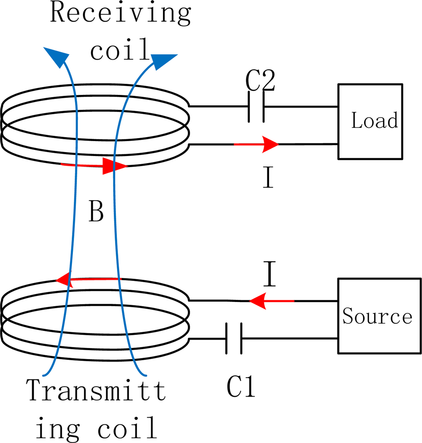
Fig. 1. Diagram of the structure of the two coils.

Fig. 2. Equivalent circuit model of the two coils.
A) Theoretical derivation of the coefficient of mutual induction
The equivalent circuit theory and the coupled-mode theory are used to analyze the transmission efficiency of the system. The coupled-mode theory analyzes from the perspective of a system's energy and skips the complex physical models, which means that an accurate, simple, and intuitive analysis framework can be established. The equivalent circuit theory is used to establish a circuit model between the transmitting and receiving coils, and the equivalent relationship is identified according to the theory of mutual inductance and Kirchhoff's Law, from which the system can be solved. The main principle of magnetic resonance is to receive the coil's resonance and obtain its magnetic field. When the system's operating frequency is within 1 MHz or even several MHzs and the wavelength of the system is much larger than the transmission distance, the magnetic field method can be used to conduct an analysis. The theoretical derivation process for magnetic resonance wireless energy transfer systems given in this paper therefore comes from the theory of the electromagnetic field. In this paper, a two-coil structure is used as the model for derivation. Two kinds of coil structures are respectively deduced: the magnetic field distribution formulas for circular–circular and rectangular–rectangular structures. In this paper, it is the situation of two parallel coils that is mainly considered, regardless of their angles.
B) The circular coil model
Figure 3 shows the model of a circular coil. It is assumed that the circular coils are filamentary and have a uniform current distribution. The number of turns of the circular transmitting coil is N 1, and their radius is R T ; the number of turns of the circular receiving coil is N 2 , and their radius is R S , here R S = R T . The current in the receiving coil is I 1, and according to the Biot–Savart Law, the magnetic field and the mutual inductance of the current I 1 at any point in the space are shown in the following formula:
 $${\mathop{B}\limits^{\rightharpoonup}} = \displaystyle{{\mu _0 I_1} \over {4\pi}} \int_C {\left( {\displaystyle{{d {\mathop{l}\limits^{\rightharpoonup}} \times {\mathop{R}\limits^{\rightharpoonup}} } \over {R^3}}} \right)}, $$
 $$M_{12} = \displaystyle{{N_2} \over {I_1}} \int_{S_2} {{\mathop{B}\limits^{\rightharpoonup}}_1 \bullet d {\mathop{s}\limits^{\rightharpoonup}}_2}. $$

Fig. 3. Schematic drawing of two parallel circular coils.
The magnetic induction intensity of the current I 1 at any point P(r, θ, φ) in the space is irrelevant to the azimuth angle φ, and the magnetic induction intensity generated at any point in the space is symmetrical about the Z-axis, and so φ is set at zero. The intersection point of the receiving coil and axis Z is taken as the origin of the coordinate o′. For the calculation, the circular coil is subdivided and the area of each circular ring is ds 2 and so it can be considered that the magnetic induction intensities of any point on ds 2 are equal to the magnetic induction intensity of P and are in the same direction.
 $${R}{}^{\hskip-6pt\rightharpoonup} = (ztg\theta - R_T \cos \varphi ^{\prime}){{i}{}^{\hskip-4pt\rightharpoonup}} - R_T \sin \varphi ^{\prime}{{j}{}^{\hskip-4pt\rightharpoonup}} + z{{k}{}^{\hskip-5pt\rightharpoonup}}, $$
 $$d\! {\,{l}{}^{\hskip-4pt\rightharpoonup}} = R{}_T\sin \varphi ^{\prime}d\varphi ^{\prime} {{i}{}^{\hskip-4pt\rightharpoonup}} + R_T \cos \varphi ^{\prime}d\varphi ^{\prime}{{j}{}^{\hskip-6pt\rightharpoonup}}, $$
 $$\eqalign{& d{{l}{}^{\hskip-6pt\rightharpoonup}} \!\!\times {{R}{}^{\hskip-7pt\rightharpoonup}} = zR_T \cos \varphi ^{\prime}d\varphi ^{\prime} {{i}{}^{\hskip-6pt\rightharpoonup}} + zR_T \sin \varphi ^{\prime}d\varphi ^{\prime}{{j}{}^{\hskip-6pt\rightharpoonup}} \cr & \quad\quad\quad\quad+ (R_T^2 - R_T \cos \varphi ^{\prime}ztg\theta d\varphi ^{\prime}){{k}{}^{\hskip-6pt\rightharpoonup}}.} $$
Since the two coils are placed in parallel, one only needs to consider the contribution of the magnetic induction intensity in the z direction to the magnetic flux of the receiving coil.
 $$\eqalignno{B_z &= \displaystyle{{\mu _0 I_1 N_1 R_T} \over {4\pi}} \int_0^{2\pi} {\displaystyle{{(R_T - ztg\theta \cos \varphi ^{\prime})d\varphi ^{\prime}} \over {(R_T^2 + (z^2 /\cos ^2 \theta ) - 2R_T ztg\theta \cos \varphi ^{\prime})^{3/2}}}} \cr &= \displaystyle{{\mu _0 I_1 N_1} \over {4\pi}} \displaystyle{2 \over {\sqrt {R_T^2 + (z^2 /\cos ^2 \theta ) + 2R_T ztg\theta}}} \cr & \quad \times\left[\displaystyle{{R_T^2 - (z^2 /\cos ^2 \theta )} \over {R_T^2 + (z^2 /\cos ^2 \theta ) - 2R_T ztg\theta}} E + K\right].} $$
In which,
 $$E = \int_0^{\displaystyle{\pi \over 2}} {\sqrt {1 - k^2 \sin ^2 x} dx}. $$
This is called an elliptic integral of the second kind.
 $$K = \int_0^{\displaystyle{\pi \over 2}} {\displaystyle{{dx} \over {\sqrt {1 - k^2 \sin ^2 x}}}}. $$
This is called an elliptic integral of the first kind, and then
 $$k^2 = \displaystyle{{4R_T ztg\theta} \over {R_T^2 + (z^2 /\cos ^2 \theta ) + 2R_T ztg\theta}}. $$
Here, the receiving coil is decomposed into infinitesimals with an area of ds 2, and the magnetic induction intensity for each infinitesimal is both the same in size and direction. By substituting the magnetic induction intensity into the mutual inductance formula, it can be obtained that:
 $$M_{12} = \displaystyle{{N_2} \over {I_1}} \int_0^{\displaystyle{\pi \over 2}} {B_z} z^2 2\pi tg\theta \sec ^2 \theta d\theta. $$
C) The rectangular coil model
The model of the rectangular coil is shown in Fig. 4. The number of turns of the rectangular transmitter coil is N 1, and the length and the width are, respectively, L 1 and h 1; the number of turns of the rectangular receiving coil is N 2, and the length and the width are L 2 and h 2, respectively. The two coils are placed in parallel on the same axis, with the distance of z. The current in the transmitting coil is I 1, and according to the Biot–Savart Law, the magnetic field intensity of the current generated at any point in the space, as well as the mutual inductance, is shown in the following formula:
 $${\mathop{B}\limits^{\rightharpoonup}} = \displaystyle{{\mu _0 I_1} \over {4\pi}} \int_C {\left( {\displaystyle{{d{\mathop{l}\limits^{\rightharpoonup}} \times {\mathop{R}\limits^{\rightharpoonup}}} \over {R^3}}} \right)}, $$
 $$M_{12} = \displaystyle{{N_2} \over {I_1}} \int_{S_2} {{\mathop{B}\limits^{\rightharpoonup}}_1 \bullet d{\mathop{s}\limits^{\rightharpoonup}}_2}. $$

Fig. 4. Schematic drawing of two parallel rectangular coils.
It is stipulated that the counterclockwise current is positive and the plane application coordinate of the transmitting coil isx ′, y ′, z ′, while the plane of the receiving coil is represented by x, y, z. In order to make the calculation more convenient, the transmitting coil is divided into four parts. Then,
 $$d{{l}{}^{\hskip-6pt\rightharpoonup}}_a = - dy^{\prime}{{j}{}^{\hskip-4pt\rightharpoonup}}, d{{l}{}^{\hskip-4pt\rightharpoonup}} _b = dx^{\prime}{\mathop{i}\limits{}^{\hskip-5pt\rightharpoonup}}, d{\mathop{l}\limits^{\rightharpoonup}}_c = dy^{\prime}{{j}{}^{\hskip-4pt\rightharpoonup}}, d{{l}{}^{\hskip-6pt\rightharpoonup}}_d = - dx^{\prime}{{i}{}^{\hskip-4pt\rightharpoonup}}, $$
 $$\eqalign{& {{R}{}^{\hskip-6pt\rightharpoonup}}_a = (x + \displaystyle{{h_1} \over 2}){{i}{}^{\hskip-4pt\rightharpoonup}} + (y - y^{\prime}){{j}{}^{\hskip-4pt\rightharpoonup}} + z{{k}{}^{\hskip-5pt\rightharpoonup}} \cr & {{R}{}^{\hskip-6pt\rightharpoonup}}_b = (x - x^{\prime}){{i}{}^{\hskip-4pt\rightharpoonup}} + (y + \displaystyle{{L_1} \over 2}){{j}{}^{\hskip-4pt\rightharpoonup}} + z{{k}{}^{\hskip-5pt\rightharpoonup}} \cr & {{R}{}^{\hskip-5pt\rightharpoonup}} _c = (x - \displaystyle{{h_1} \over 2}){{i}{}^{\hskip-4pt\rightharpoonup}} + (y - y^{\prime}){{j}{}^{\hskip-4pt\rightharpoonup}} + z{{k}{}^{\hskip-5pt\rightharpoonup}} \cr & {{R}{}^{\hskip-5pt\rightharpoonup}} _d = (x - x^{\prime}){{i}{}^{\hskip-4pt\rightharpoonup}} + (y - \displaystyle{{L_1} \over 2}){{j}{}^{\hskip-4pt\rightharpoonup}} + z{{k}{}^{\hskip-5pt\rightharpoonup}},} $$
 $$\eqalign{& d{{l}{}^{\hskip-6pt\rightharpoonup}}_a \times {{R}{}^{\hskip-6pt\rightharpoonup}}_a = - zdy^{\prime}{{i}{}^{\hskip-4pt\rightharpoonup}} + (x + \displaystyle{{h_1} \over 2})dy^{\prime}{{k}{}^{\hskip-5pt\rightharpoonup}} \cr & d{\mathop{l}\limits{}^{\hskip-5pt\rightharpoonup}} _b \times {{R}{}^{\hskip-6pt\rightharpoonup}}_b = - zdx^{\prime}{{j}{}^{\hskip-4pt\rightharpoonup}} + (y + \displaystyle{{L_1} \over 2})dx^{\prime}{{k}{}^{\hskip-5pt\rightharpoonup}} \cr & d{{l}{}^{\hskip-6pt\rightharpoonup}} _c \times {{R}{}^{\hskip-6pt\rightharpoonup}}_c = zdy^{\prime}{{i}{}^{\hskip-4pt\rightharpoonup}} - (x - \displaystyle{{h_1} \over 2})dy^{\prime}{{k}{}^{\hskip-5pt\rightharpoonup}} \cr & d{{l}{}^{\hskip-6pt\rightharpoonup}}_d \times {{R}{}^{\hskip-6pt\rightharpoonup}} _d = zdx^{\prime}{{j}{}^{\hskip-4pt\rightharpoonup}} - (y - \displaystyle{{L_1} \over 2})dx^{\prime}{{k}{}^{\hskip-5pt\rightharpoonup}} .} $$
Since the two coils are parallel, only the magnetic field in the Z-axis direction contributes to the magnetic flux of the plane, and so the magnetic field generated by these four parts is:
 $$\eqalign{B_{zlinea} = & \displaystyle{{\mu _0 N_1 I_1} \over {4\pi}} \left( {\displaystyle{{(x + (h_1 /2))} \over {((x + (h_1 /2))^2 + z^2 )}}} \right)\left[ {\left( {\displaystyle{{y + (L_1 /2)} \over {\sqrt {(x + (h_1 /2))^2 + z^2 + (y + (L_1 /2))^2}}}} \right) - \left( {\displaystyle{{y - (L_1 /2)} \over {\sqrt {(x + (h_1 /2))^2 + z^2 + (y - (L_1 /2))^2}}}} \right)} \right] \cr B_{zlineb} = & \displaystyle{{\mu _0 N_1 I_1} \over {4\pi}} \left( {\displaystyle{{(y + (L_1 /2))} \over {((y + (L_1 /2))^2 + z^2 )}}} \right)\left[ {\left( {\displaystyle{{x + (h_1 /2)} \over {\sqrt {(x + (h_1 /2))^2 + z^2 + (y + (L_1 /2))^2}}}} \right) - \left( {\displaystyle{{x - (h_1 /2)} \over {\sqrt {(x - (h_1 /2))^2 + z^2 + (y + (L_1 /2))^2}}}} \right)} \right] \cr B_{zlinec} = & \displaystyle{{\mu _0 N_1 I_1} \over {4\pi}} \left( {\displaystyle{{ - (x - (h_1 /2))} \over {((x - (h_1 /2))^2 + z^2 )}}} \right)\left[ {\left( {\displaystyle{{y + (L_1 /2)} \over {\sqrt {(x - (h_1 /2))^2 + z^2 + (y + (L_1 /2))^2}}}} \right) - \left( {\displaystyle{{y - (L_1 /2)} \over {\sqrt {(x - (h_1 /2))^2 + z^2 + (y - (L_1 /2))^2}}}} \right)} \right] \cr B_{zlined} = & \displaystyle{{\mu _0 N_1 I_1} \over {4\pi}} \left( {\displaystyle{{ - (y - (L_1 /2))} \over {((y - (L_1 /2))^2 + z^2 )}}} \right)\left[ {\left( {\displaystyle{{x + (h_1 /2)} \over {\sqrt {(x + (h_1 /2))^2 + z^2 + (y - (L_1 /2))^2}}}} \right) - \left( {\displaystyle{{x - (h_1 /2)} \over {\sqrt {(x - (h_1 /2))^2 + z^2 + (y - (L_1 /2))^2}}}} \right)} \right].} $$
Then the magnetic field at P is the sum of the four parts of the magnetic field:
 $$B_{ztotal} = B_{linea} + B_{lineb} + B_{linec} + B_{lined}. $$
The receiving coil is decomposed into infinitesimals with small N L N h , and the magnetic field for each infinitesimal can be seen as a uniform magnetic field, and the magnetic field for each point is of the same size and direction. Then the mutual inductance of the two coils can be computed through integration.
 $$M_{12} = \displaystyle{{N_1 N_2 d_L d_h} \over {I_1}} \sum\limits_{i = 1}^{N_L = L_2 /d_L} {\sum\limits_{i = 1}^{N_h = h_2 /d_h} {\left \vert {B_{zi}} \right \vert}}. $$
It can be shown from the analysis that the mutual inductance not only relates to the magnetic field of the receiving coil at each point but also relates to the area of the receiving coil.
III. SIMULATION ANALYSIS
In this paper, finite element analysis software is used to undertake a simulation analysis of the magnetic resonance energy transfer systems using different shapes of resonant coils. The reflection coefficients for the single and multi-turns transmitting and receiving coils that are both circular coils are simulated, and the reflection coefficients of the single and multi-turns transmitting and receiving coils where both are rectangular coils are also simulated. The transmission efficiencies of the systems are then obtained through their transmission coefficients. In the simulation model, a copper coil is used, and the cross-section of the copper coil is a circle with a radius of 1 mm. Figures 5 and 6, respectively, show the magnetic coupling resonant models of single-circle circular resonant coil and the magnetic resonance model of the rectangular resonant coil.

Fig. 5. The resonances power transfer model of the circular coil.

Fig. 6. The resonances power transfer model of the rectangular coil.
The simulation models shown in Figs 5 and 6 are the wireless energy transmission systems of the single-turn two-coil structure, and their inductances and capacitances are both generated by a lumped parameter, which simulates their actual capacitances and inductances; the resonant frequency of the system is 6.4 MHz. The radius of the circular coil is 10 cm, and the material is copper; the cross-section is a circle with a radius of 1 mm, and the sizes of the transmitting and receiving coils are exactly the same. The length of the side of the rectangular coil is 17.8 cm, and the sizes of the transmitting and receiving coils are also the same. The area of the rectangular coil is equal to that of the circular coil. The simulation results are shown in Section V.
IV. EXPERIMENTAL VERIFICATION
In order to verify whether the theoretical analysis was correct, magnetic resonance wireless energy transfer systems of different sizes were constructed using circular and rectangular coils. The diameters of the circular coils were 20, 16, and 10 cm, respectively, and each had four turns. The lengths of the sides of the rectangular coils were 17.8, 14, and 9 cm, respectively, and each also had four turns. The system was driven by a signal generator, which generated a 6.4 MHz sinusoidal signal in its transmitting coil, and which was the system's power source. An oscilloscope was used to measure the output voltage at both ends of the load resistor, thereby providing the transmission efficiency of the systems. The transmission efficiencies of the magnetic resonance wireless energy transfer systems composed of the circular coils as well as the rectangular coils were then compared, and also compared with the simulation results. At the same time, in order to verify the correctness of the theoretical derivation formula, the mutual inductances of the two systems was measured at different distances, and then compared with the theoretical formula.
The transmission efficiencies of systems when the transmitting and receiving coils are of different shapes are compared in this paper, so that the integrity of the systems can be examined. Figures 7 and 8 show pictures of the experimental apparatus used for the rectangular and circular coils.

Fig. 7. The structure of the rectangle coils.

Fig. 8. The structure of the circular coils.
V. RESULTS AND DISCUSSION
A) Analysis of the mutual inductances
In order to confirm the influence of the mutual inductances on the wireless energy transmission systems, the mutual inductances of the theoretical calculation results and that of the experimental measurements were compared in this paper, and we found that the theory was basically in agreement with the experiments.
Figure 9 shows a comparison between the theoretical and experimental values of the mutual inductances for circular coils of different sizes at different transmission distances. The 20, 16, and 10 cm lengths in the legends, respectively, represent the diameters of the circular coils. As can be seen from Fig. 9, the larger the receiving area, the greater the mutual inductance of the two resonant coils. Figure 10 shows the theoretical and experimental values of the mutual inductance for two rectangular resonator coils when the side lengths of the rectangular coils are 17.8, 14, and 9 cm, respectively, and the results are consistent with that of the circular coils. Additionally, the mutual inductances of the rectangular and circular coils with the same areas were also compared in this paper, as shown in Fig. 11, and it was found in both the experimental measurements and theoretical analysis that the mutual inductances of the circular coils were slightly larger than that of the rectangular coils.

Fig. 9. The mutual inductance of circular coils at different distances.

Fig. 10. The mutual inductance of rectangular coils at different distances.
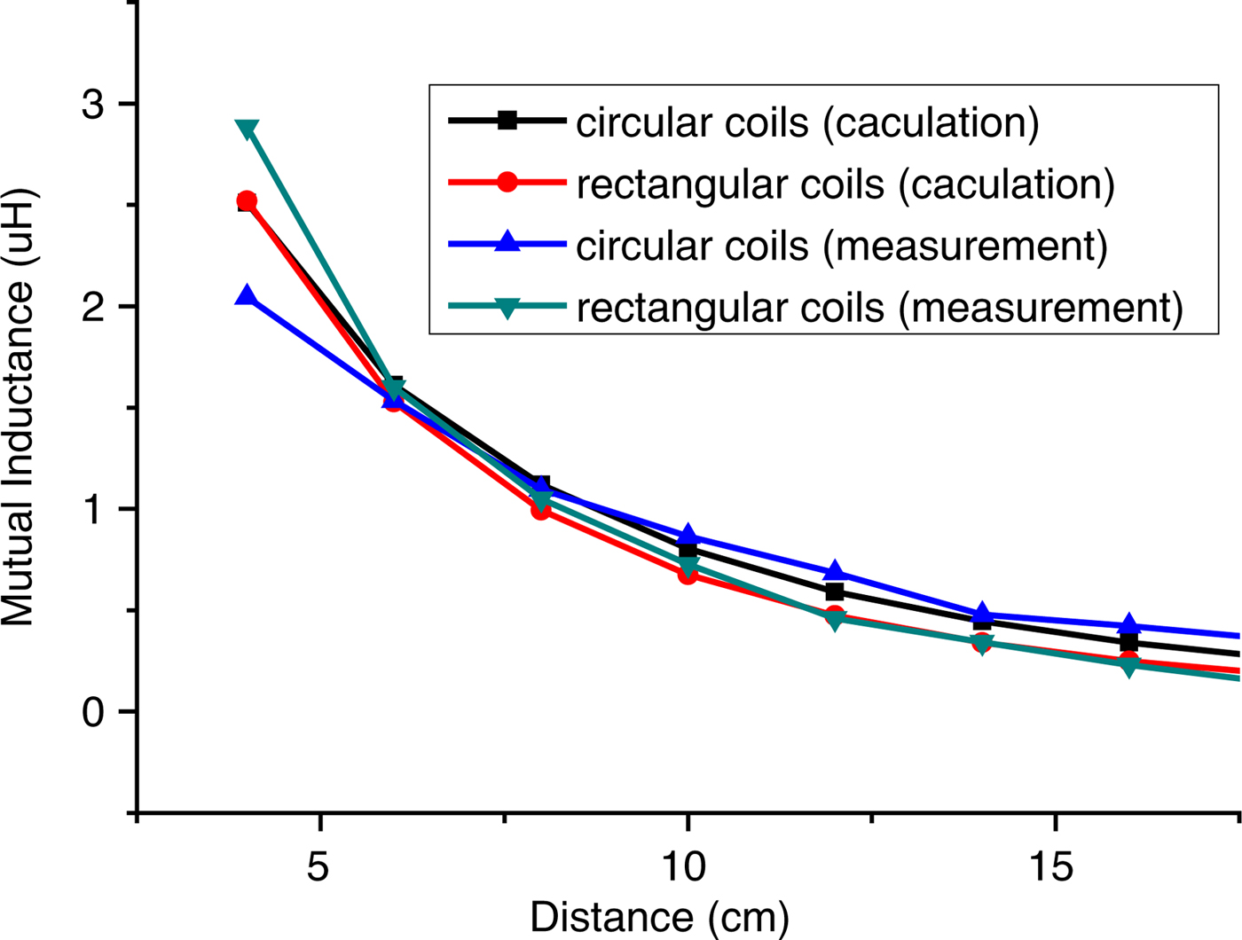
Fig. 11. Comparison between the calculated and measured mutual inductance of circular and rectangular coils.
B) The transmission efficiency analysis
The transmission efficiency of the wireless energy transfer systems at different distances was measured and simulated in this paper on the basis of an analysis of the mutual inductances for the resonant coils.
Figures 12 and 13 show the experimental transmission efficiency diagrams for circular and rectangular coils of different sizes and distances. Figure 14 shows the simulation analysis transmission efficiency diagrams for circular and rectangular coils with a different number of turns in the resonant coils. In addition, the experimental and the simulated results for circular and rectangular coils with four turns and the same area are compared and shown in Fig. 15.

Fig. 12. The experimental results of transfer efficiencies of circular coils at different distances.

Fig. 13. The experimental results of the transfer efficiencies of rectangular coils at different distances.

Fig. 14. The transfer efficiencies of circular and rectangular coils with a different number of turns.

Fig. 15. Comparison between the simulated and measured efficiencies.
Figures 12 and 13 show the transmission efficiency diagrams for the actual measurements of the magnetic resonance wireless energy transfer systems. The legend represents the size of the coil, and the X-axis represents the transmission distance. The diameters of the circular coils are 20, 16, and 10 cm, respectively, and the lengths of the sides of the square coils are 17.8, 14, and 10 cm, respectively.
As can be seen in Figs 12 and 13, the transmission efficiency, for both the rectangular and the circular coils, decreases as the transmission distances increase. However, when the size of the coils increases, the transmission efficiency of the resonant coils does not necessarily increase, and rectangular and circular coils both have an optimum size. As shown in Fig. 12, the transmission efficiency of the circular resonant coil with a diameter of 16 cm is higher than that of the resonance coil with a diameter of 20 cm. In addition, under the same conditions, the transmission efficiency of the circular coil is slightly higher than that of the rectangular coil, as shown in Fig. 15.
C) An analysis of the wireless energy transmission systems for different topological structures
The above theoretical analysis, software simulations, and experimental measurements only considered resonant coils where all the transmitting and receiving coils were of the same shape and parameters. For the sake of completeness, the wireless energy transmission systems of circular transmitting coils and rectangular receiving coils were measured by means of an experiment. In addition, the wireless energy transmission systems of rectangular transmitting coils and circular receiving coils were simulated as well. Finally, the transmission efficiencies and mutual inductances of wireless energy transfer systems with four kinds of topology were also measured and compared.
In Figs 16 and 17, the 20 cm circular coil represents circular transmitting and receiving coils with diameters of 20 cm. The rectangular coil of 17.8 cm represents transmitting and receiving rectangular coils with side lengths of 17.8 cm. The 17.8–20 cm line represents rectangular transmitting coils with side lengths of 17.8 cm and circular receiving coils with a diameter of 20 cm. The 20–17.8 cm line represents circular transmitting coils with a diameter of 20 cm and rectangular receiving coils with side lengths of 17.8 cm.
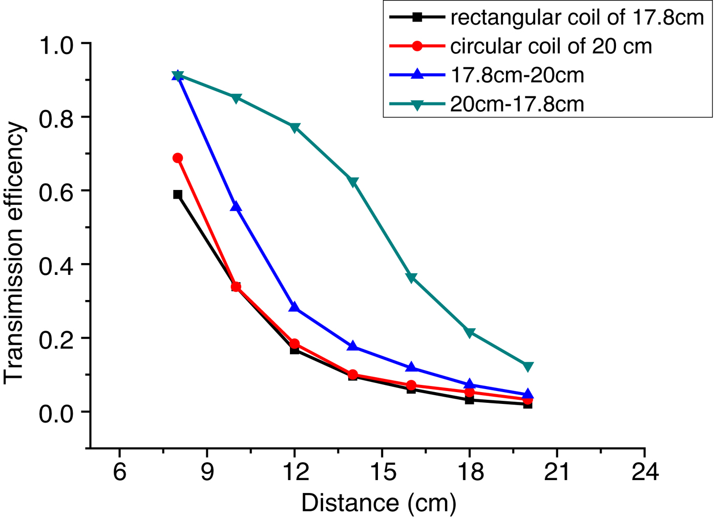
Fig. 16. The transfer efficiencies of different topological structures.
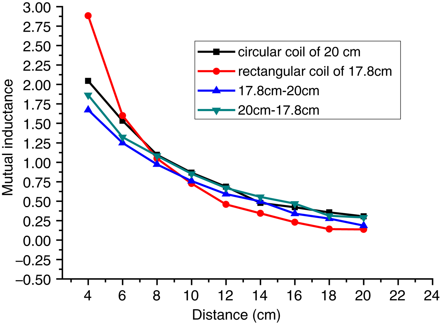
Fig. 17. The mutual inductances for different topological structures.
As can be seen in Figs 16 and 17, the 17 cm rectangular wireless transmission system has the lowest mutual inductance and transmission efficiency, while the 20–17.8 cm wireless transmission system has the highest transmission efficiency and mutual inductance.
VI. CONCLUSION
In this paper, the magnetic field distributions and mutual inductances of circular and rectangular coils are worked out, and the transmission efficiency of the wireless energy transfer systems is analyzed using finite element method. In addition, the mutual inductances and transmission efficiencies are measured in an experiment to verify the correctness of the theoretical derivation. This can all be summed up through the following points:
-
(1) It is appropriate to use the magnetic field equation to analyze the mutual inductances of the wireless energy transfer systems, so as to predict the transmission efficiencies of the wireless energy transmission systems and to explore any new ideas when studying magnetic resonance wireless energy transfer systems. We thus hope that this paper will prove to be useful in the study of wireless transfer technology.
-
(2) Through our magnetic field analysis modeling, it was shown that if the coils were of different shapes and their magnetic fields were of different sizes, the magnetic fluxes of the coils would be different, which would result in the magnetic resonance wireless transmission systems having different transmission efficiencies. Therefore, improving transmission efficiency by changing the magnetic fluxes of the receiving coils or the intensity of the magnetic fields provides a future direction for improving the transmission efficiencies of the magnetic resonance wireless energy transmission systems.
-
(3) Through our simulation analysis and experimental verification, it was found that in conditions where the areas and the power inputs were the same, the transmission efficiency of the circular coil was slightly higher than that of the rectangular coil when the transmitting coil was a circular coil; the rectangular receiving coil had the highest transmission efficiency. Therefore, according to different requirements, the size and shape of the transmitting and receiving coils should be reasonably calculated and optimized for practical applications.
ACKNOWLEDGEMENT
This work was supported by the open research fund of Computational Physics Key Laboratory of Sichuan Province, Yibin University (No. JSWL2014KF01).
 Xiufang Wang was born in Shandong Province, China, in 1980. She received the M.S. degree in Physics in 2006 from Sichuan University, Chengdu, China. She is currently pursuing the Ph.D. degree in Theory of Electrical Engineering and New Technology. She is currently with the School of Electrical Engineering, Southwest Jiaotong University, Chengdu, China. Her research interests include superconducting metamaterial and wireless power transfer.
 Yu Wang was born in Henan Province, China, on November 7, 1960. He received the Ph.D. degree in Physical Electronics from the Huazhong University of Science and Technology, Wuhan, China, in 2001. He is currently a Professor with the School of Electrical Engineering and the Key Laboratory of Magnetic Suspension Technology and Maglev Vehicle, Southwest Jiaotong University, Chengdu, China. His current research interests include superconducting electrotechnics and material technology.
 Yilang Liang was born in Chongqing Province, China, on April 5, 1990. He received B.S. degree in School of Physics and Electronic Engineering from Chongqing Three Gorges University, Chongqing, China, in 2014. He is currently pursuing the Master's degree in Physics from Southwest Jiaotong University. His main research includes non-destructive testing and numerical simulation of electromagnetic fields.
 Guangcheng Fan was born in Shandong Province, China, on January 29, 1991. He received B.S. degree in Electrical Engineering from Qingdao University, Qingdao, China, in 2015. He is currently pursuing the M.E. degree in Theory of Electrical Engineering and New Technology from Southwest Jiaotong University. His research interests include superconducting application and electromagnetic field numerical simulation.
 Xinyi Nie was born in Henan Province, China, in 1989. He received the B.S. degree in Information Science and Technology in 2014 from Huanghe Science and Technology College, Zhengzhou, China. He is currently pursuing the M.S. degree in Theory of Electrical Engineering and New Technology. He is currently with the School of Electrical Engineering, Southwest Jiaotong University, Chengdu, China. His research interests include wireless power transmission.
 Zhongming Yan was born in Zhejiang Province, China, on July 12, 1982. He received the Ph.D. degree in Theory of Electrical Engineering and New Technology from Southwest Jiaotong University, Chengdu, China, in 2010. He is currently a Associate Professor with the School of Electrical Engineering, SWJTU. His research interests include superconducting electromotor and numerical analysis of electromagnetic fields.
 Qingying Xu was born in Henan Province, China, in 1990. She received the B.S. degree in Electrical Engineering and Automation from the Southwest Jiaotong University, Chengdu, China, in 2014, where she is currently pursuing the M.S. degree in Theory of Electrical Engineering and New Technology. Her current research interests include pulsed power technology and its applications.


