I. INTRODUCTION
High spectral purity microwave sources are very important for space and military applications, and also for time and frequency metrology. As is commonly known, the quality factors of microwave resonators degrade when the application frequency (f RF) increases. This leads to the degradation of spectral purity of microwave signals generated by the oscillators based on these resonators. Therefore, achieving ultrahigh spectral purity in compact oscillators is linked to investigations on new high-quality factor resonators (or delay mediums) also having the lowest dissipation factors.
Optics represents an elegant and reliable solution to generate high spectral purity microwave signals, especially the approach using the optoelectronic oscillator (OEO). The first OEO merging optics and microwaves was based on a long optical delay line (few kilometers optical fiber) [Reference Yao and Maleki1]. Indeed, the use of the optical delay line can lead to extremely high equivalent microwave quality factors (Q RF above 106 at 10 GHz) and therefore to ultra-low-phase noise levels [Reference Yao, Eliyahu and Maleki2]. On the other hand, and despite good noise performances, the optical delay line-based oscillator is still bulky, its thermal stabilization is difficult, and it produces spurious modes which need complex architectures to be reduced [Reference Eliyahu and Maleki3, Reference Okusaga4].
An alternative solution to stabilize the frequency of the OEO is the use of an optical resonator instead of using an optical delay line [Reference Maleki, Yao, Yu and Ilchenko5, Reference Savchenkov, Matsko, Ilchenko and Maleki6]. Actually, the optical resonator acts simultaneously as a delay element and an optical filter. It filters the microwave signals carried as modulation sidebands on an optical carrier. Moreover, optical quality factors (Q Opt) ranging from 108 to 1011 can be obtained with different types of passive optical resonators: fiber ring resonators (FRRs), whispering gallery mode (WGM) micro-resonators (disks, silica spheres, or toroids), Fabry–Perot ultra-stable cavities, etc. In addition, when using these passive optical resonators, the equivalent microwave quality factor is linked to the optical quality factor by the following relation [Reference Merrer, Brahimi and Llopis7]:
 $$Q_{RF} = Q_{Opt} \times \displaystyle{{f_{RF} } \over {f_{Opt} }},$$
where f Opt is the frequency of the optical carrier.
From (1), we can see that interestingly, and unlike microwave resonators, the equivalent Q RF of the optical resonators increases when the RF application frequency increases. As an example, a Q Opt of 109 at 1.55 µm wavelength (f Opt ~193 THz), results in an equivalent Q RF of 105 at 20 GHz application frequency. This Q RF value is a bit lower than the equivalent Q RF that can be achieved using a long optical delay line but it is still particularly interesting if compared to the Q RF obtained with conventional microwave resonators. Moreover, one also has to take into account the drastic reduction in system size if we replace a few kilometers-long optical delay line by an FRR of a few meters or by a micro-resonator with a diameter of a few millimeters.
A special case of a resonator-based OEO is the coupled OEO (COEO) [Reference Matsko, Eliyahu, Koonath, Seidel and Maleki8] where a microwave oscillator is coupled to an optical oscillator. In this case, the optical oscillator is an active FRR including an optical amplifier and therefore the resonator acts like a mode-locked fiber laser. Moreover, an optical modulator is directly integrated inside the resonator loop to perform direct gain modulation in the fiber laser. This COEO architecture allows a reduction in fiber length while keeping high performances such as in the classical resonator-based OEO case. On the other hand, system size and Q Opt factor can be competitive in passive resonator-based OEOs if noise conversion problems can be efficiently resolved.
In this paper, noise processes occurring inside OEOs based on either an FRR or a tridimensional monocrystalline micro-resonator are discussed. All these OEOs use the same laser stabilization system to stabilize the optical carrier onto the resonator: a Pound–Drever–Hall (PDH) technique [Reference Drever, Hall, Kowalski, Hough, Ford, Munley and Ward9], which is briefly explained in Section II. The noise processes are theoretically and experimentally studied in these OEOs, especially those related to the laser's amplitude (AM) and frequency (FM) noise conversions into RF phase noise. We also report on a modeling approach using microwave CAD software (Agilent ADS) to qualitatively evaluate laser noise conversion through the optical resonator. Besides that, the noise contributions of nonlinear optical effects generated inside the FRR are discussed and different experimental results are also provided.
II. OEO BASED ON PASSIVE OPTICAL RESONATORS
A) Microwave filtering using passive resonators
The OEO presented in this paper is based on two different passive optical resonators featuring ultra-high Q Opt: an FRR and a WGMs micro-resonator. These resonators generate a comb of resonances with microwave spacing called free spectral range (FSR). When used for RF applications, the resonator FSR must be a sub-multiple of the application frequency. In this case, the beat note between two or three optical modes of the resonator will be used in the microwave domain. Nevertheless, it is necessary to stabilize the laser carrier onto one of the optical modes of the resonator before setting up filtering of the microwave signal carried by the laser carrier (see the illustration in Fig. 1).

Fig. 1. Illustration of microwave filtering using an optical frequency comb generated by an optical resonator.
B) Laser stabilization
The extreme quality factors of these resonators make them very sensitive to the incident optical power. Actually, when the optical carrier is resonant inside the resonator, the circulating intra-cavity power can be tens to hundreds of times higher than the incident optical power, depending on the resonator Q Opt. As a result, this high intra-cavity power induces a strong thermal variation inside the resonator [Reference Carmon, Yang and Vahala10] and causes a shift in the resonator's optical resonances. Therefore, the laser carrier is no more coupled to the resonator unless a feedback system is used to maintain laser frequency stabilized onto the resonator's resonant frequency. In addition, this high intra-cavity power can lead to the generation of many nonlinear optical effects inside the resonator, which contribute to the degradation of the OEO phase noise as we will see later in Section V.
Many feedback approaches can be used to stabilize the laser onto an optical mode of the resonator. First, using WGM disks or sphere micro-resonators, one can take benefit of a natural counter-propagating wave inside the resonator to optically lock the laser onto the resonator [Reference Maleki11]. Of course, this requires accurate control of the resonator-to-laser distance. A self-thermal lock can also be used in some cases, depending on the thermal expansion coefficient of the resonator, but such a stabilization technique cannot be reliable enough for all applications. The approach we have chosen, the PDH technique, is based on an electrical feedback to the laser: phase transition at the resonance is converted into an error signal and fed-back to control the laser frequency. This approach is very reliable in time and it can be applied to any laser having a smaller linewidth than the optical resonance linewidth and in which a frequency control driver is available.
C) Optoelectronic oscillator setup
The OEO setup, depicted in Fig. 2, consists of three parts: an optical loop, a high-frequency loop, and a low-frequency loop. The optical loop consists of a laser, an optical modulator (a Mach–Zehnder modulator, MZM), an optical resonator, and a fast photodiode. Eventually, an optical amplifier can be included in the optical loop after the resonator. The laser carrier is first stabilized onto the resonator, thanks to the PDH low-frequency loop, and the microwave oscillation is then started thanks to the high-frequency loop. This high-frequency loop includes an RF amplifier, a phase shifter and, in the case of the FRR-based OEO, an RF mode selection filter. This RF filter can also be replaced by an optical filter in the optical loop.

Fig. 2. OEO setup based on a low-frequency (LF) PDH loop to stabilize the laser onto the resonator and a high-frequency (HF) loop to maintain the microwave oscillation; PDH: Pound–Drever–Hall, MZM: Mach–Zehnder modulator.
This filter is used in the FRR-based OEO because the FSR of the 20 m-long FRR that we are using is around 10 MHz and it can therefore generate close-to-carrier spurious modes in the phase noise spectrum of the OEO's generated microwave signal. Furthermore, these spurious modes can also lead to oscillation mode hopping in the OEO. This is not the case of the WGM micro-resonator, which is of millimeter size, in which the resonant comb features an FSR higher than 12 GHz. Therefore, the microwave filter is useless in the case of OEOs based on WGM resonators.
III. WGM OPTICAL MICRO-RESONATOR
In the micro-resonator-based OEO, we have studied a calcium fluoride (CaF2) WGM disk-shaped micro-resonator (see Fig. 3(a)), and a silica sphere-shaped micro-resonator. In both cases, the micro-resonators were coupled to the laser thanks to a symmetrical dual-coupling technique using two tapered optical fibers and a Nano-scale accurate positioning system (see Figs 3(b) and 3(c)).

Fig. 3. (a) A 5.5 mm-diameter WGM CaF2 disk-shaped micro-resonator fixed on a metallic rod; (b) illustration; and (c) experimental setup of symmetrical dual-coupling using two tapered optical fibers coupled to the CaF2 disk.
Such a coupling technique is very efficient, but it remains a laboratory technique that cannot be used for embedded systems. Actually, one of the main problems usually encountered when using micro-resonators is mechanical difficulty in setting up reliable coupling with a light source. Besides that, and in addition to the fundamental frequency comb they generate (equatorial mode), other multiple optical frequency combs are generated by these micro-resonators corresponding to both transverse electric (TE) and transverse magnetic (TM) modes. The use of an all-fiber polarization controller before the WGM resonator is therefore imperative so as to be able to select TE or TM mode's frequency combs.
When characterizing the silica sphere and the CaF2 disk, using an accurate microwave characterization technique (well explained in [Reference Merrer, Saleh, Llopis, Berneschi, Cosi and Nunzi Conti12]), we have obtained a Q Opt value in the range of 108. Of course, higher Q Opt can be obtained if the resonator shape and fabrication are well managed. Moreover, Q Opt as high as 1011 have been already demonstrated with CaF2 disks [Reference Savchenkov, Matsko, Ilchenko and Maleki6].
IV. FIBER RING RESONATOR
The FRR is a simpler type of optical resonator than the WGM micro-resonator. It is basically made of two low loss fibered 2 × 2 optical directional couplers (C1 and C2), which are stable, easy to fabricate and to use, and are commercially available. These two couplers are linked together with a few meters-long single-mode and polarization maintaining optical fiber (see Fig. 4). The FRR has therefore a two-dimensional structure which can be easily integrated and in which only two similar optical frequency combs are generated (TE mode's frequency comb and TM mode's frequency comb). The selection of one of these two frequency combs can be made by using a polarization controller before the FRR. Of course, the comb selection method can be improved by adding a beam polarizer at the FRR input. Therefore, it is easier to characterize and use an FRR than a WGM micro-resonator.

Fig. 4. Fiber ring resonator.
In our laboratory, the FRR has been first used for the aim of understanding the WGM micro-resonator's behavior because of similarity in their resonance conditions. However, we have rapidly realized that the FRR, in addition to its fabrication simplicity, is able to reach relatively higher quality factors (Q Opt > 109) than the aforementioned micro-resonators we were using. As an example, we have been able to obtain a Q Opt of 5.1 × 10⁹ with a 20 m-long FRR, which means an equivalent Q RF of 5.1 × 10⁵ at 20 GHz application frequency. Such a Q RF value is higher than the quality factor's values obtained when using conventional microwave resonators.
V. NOISE IN THE RESONATOR-BASED OEO
Unlike microwave oscillators, in which phase noise is dominated by RF amplifiers noise, the phase noise in OEOs is generally dominated by noise processes occurring in the optical part of the system. This is even more true for resonator-based OEOs in which the required correlation between the laser frequency and the resonator's resonant frequency may induce specific noise processes. Moreover, the resonator ultra-high Q Opt factor may lead to an induced nonlinear optical scattering noise inside the resonator, which is then converted into microwave phase noise via the OEO nonlinearity.
Two types of laser noise conversion processes are particularly important: the laser AM and FM noise conversions. Since the photodiode performs amplitude detection, it is obvious that the laser AM noise may have an influence on microwave phase noise. Moreover, this is generally the main parameter which determines the signal-to-noise ratio (unless the resonator insertion loss (IL) is very high) and therefore the far-from-carrier OEO phase noise. However, for most applications, the close-to-carrier phase noise performance (at the 1 Hz to 10 kHz offset frequencies) is the most critical parameter. At these offset frequencies, a 1/f like frequency noise is usually observed.
A) Fiber ring resonator modeling using ADS
To determine the ratio of the laser AM and FM noise conversion into RF phase noise, a modeling approach has been employed using the Agilent ADS microwave CAD software. This approach takes benefit of the harmonic balance technique provided by ADS to describe the nonlinear signal and noise conversion processes occurring in the OEO between the laser frequency (~193 THz), the microwave frequency and the DC [Reference Brahimi, Martinez-Reyes, Merrer, Bouchier and Llopis13].
Since ADS does not include models for optical devices, we have developed our own models (laser, MZM, FRR, photodiode, etc.), which were either based on equivalent circuit descriptions or on mathematical black box descriptions [Reference Brahimi, Martinez-Reyes, Merrer, Bouchier and Llopis13]. As an example, the laser is described as a classical frequency source with its FM noise, and an amplitude modulator is added after this source to model the laser AM noise.
Of course, the first element to add to our microwave-optical models, to be able to simulate the global OEO system, is the optical resonator. For this purpose, we have developed an equivalent model of the FRR using ADS (depicted in Fig. 5). In this case, the FRR has been modeled and described using modified models of ideal lines and couplers offered by ADS components library. The models we created can describe the real behavior of optical fibers and optical couplers operating at the optical frequency f Opt.

Fig. 5. FRR model created using ADS.
Using this modeling approach, when simulating the OEO optical link in an open-loop configuration (laser + modulator + optical resonator + photodiode), the characteristics of the FRR (frequency comb, FSR, quality factor, etc.) have been accurately modeled on any of the four ports of the resonator. The ADS simulation results for the 20 m-long FRR we are using in our experiments are presented in Fig. 6. They demonstrate complete agreement with our experimental results. Furthermore, the simulation results, like the experimental results, show the effect of photodiode quadratic detection, where FRR IL in the optical domain (~3.5 dB) is doubled (in dB) in the RF domain (~7 dB).

Fig. 6. Transmission amplitude response of a 20 m-long FRR: (in dashed red) simulated using the ADS open-loop model and (in green) measured using the microwave characterization bench detailed in [Reference Merrer, Saleh, Llopis, Berneschi, Cosi and Nunzi Conti12].
B) Modeling of compound and complex FRR-based architectures
Another important advantage of the FRR ADS model is the ease in simulating very complex schemes based on multiple optical FRRs. These schemes are usually hard to describe analytically and then to simulate using a mathematical software.
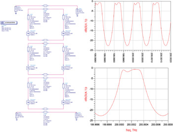
In Fig. 7, we present an example of an ADS model, and the simulation results, of a high rejection optical filter based on three compound FRRs with different parameters each and a total length of <1 m. This model can be created and simulated in a few minutes only, using the basic FRR model described in the section above. Such a structure would need much more time to be analytically described, then coded and simulated using a mathematical software.

Fig. 7. ADS model and transmission response simulation results of a high rejection optical filter based on three compound FRRs with a total length of <1 m.
C) Laser noise conversion investigated using ADS
For our OEO application and noise investigations, an interesting study which can be performed using ADS is on the way the optical modes are translated into electrical resonances in the aforementioned OEO in open-loop configuration.
If a classical Mach–Zehnder linear modulation is used (V bias = V π/2), the modulated laser carrier features two optical sidebands which simultaneously go through two lateral modes of the resonator (see the illustration in Fig. 1). This process gives birth to a unique microwave mode at the photodiode output, which results from the two optical modulation sidebands and the laser carrier folded one onto the other.
If the laser is perfectly centered onto one of the optical modes of the resonator, and the two lateral sidebands are identically spaced, then a microwave mode, identical to the resonator optical mode (same 3 dB bandwidth and phase slope), is obtained in the microwave domain. However, if the laser is stabilized onto one of the edges of the optical mode, the amplitude response and the phase slope in the microwave domain (and thus the Q RF factor) are distorted. These simulation results, presented in Fig. 8, fit quantitatively well with the experimental results we have obtained when stabilizing the laser frequency onto one of the edges of the optical resonance of a FRR.

Fig. 8. Experimental and ADS simulation results of RF amplitude and phase responses of the OEO optical link in an open-loop configuration (laser + modulator + optical resonator + photodiode). Both results fit quantitatively well as they show that the resonance RF amplitude and phase responses are deformed when the laser frequency is stabilized onto one of the edges of the optical resonance.
In this configuration, the system becomes sensitive to laser frequency fluctuations, and therefore it is able to convert the laser phase noise into RF phase and amplitude noise. These simulation results demonstrate how important is the laser lock and the ability to control this locking process. Such a possibility is well provided by the PDH laser stabilization technique we are using in our OEO experimental setup.
D) Optical scattering noise in the FRR
Another problem encountered in these OEO systems relies on starting up of nonlinear optical effects inside the resonator due to high circulating intra-cavity power. Through our investigations on noise processes in the OEO, we have found that the generation of these effects leads directly to the degradation of OEO phase noise [Reference Saleh, Merrer, Llopis and Cibiel14]. The two main processes that were particularly considered are the Rayleigh and the Brillouin scatterings.
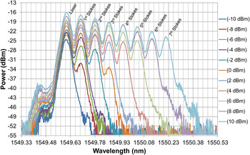
Actually, we have experimentally found that the stimulated Brillouin scattering (SBS) can be generated at relatively low input power in the case of the FRR [Reference Saleh, Merrer, Llopis and Cibiel14], depending on its Q Opt factor. Once this process starts, the first Brillouin Stokes wave back-scattered (see Fig. 4) and downshifted in frequency from the laser carrier by about 10.8 GHz (for silica fibers) can be observed. Using a 20 m-long FRR, and because of its high intra-cavity power enhancement factor (the intra-cavity power is ~54 time higher than the injected input power), we have been able to detect the generation of the seventh order Brillouin line when injecting a 10 dBm optical power at the resonator input (see the experimental results depicted in Fig. 9). These parasitic signals mix either inside the resonator (they modulate the amplitude of the main signal) or at the photodiode with the main laser carrier signal. As a consequence, the close-to-carrier phase noise of the OEO's microwave generated signal is particularly increased.

Fig. 9. Multiple SBS lines generated inside a 20 m-long FRR featuring a Q Opt factor of 3.5 × 10⁹.
Moreover, the generation of the SBS inside the FRR also leads to nonlinear losses inside the resonator which will be added to the resonator intrinsic loss. After being generated, above the SBS threshold, the first Brillouin Stokes wave converts any additional laser power injected above this threshold to its own power and generates other higher order Brillouin lines. Consequently, the laser carrier saturates at the FRR output, and the noise-to-carrier ratio of the optical link inside the OEO loop is therefore degraded.
Figure 10 shows optical power measurements of the laser carrier and of both first and second SBS Stokes waves, at the second and third outputs of the 20 m-long FRR (see Fig. 4 for different waves’ traveling directions), versus the laser input power. The optical power measurements were performed using an Agilent HP 86142A optical spectrum analyzer with 0.06 nm resolution and ±1 dB amplitude precision. From these measurements one can clearly notice saturation of the laser carrier after generation of the first SBS Stokes wave.

Fig. 10. Optical power measurements of the laser carrier and of both first and second SBS Stokes waves, at the second and third outputs of the 20 m-long FRR, versus the laser input power.
Therefore, good close-to-carrier OEO phase noise performance can be only obtained when low optical power is injected at the FRR input (below the first SBS Stokes wave's threshold), unless a specific FRR configuration is made to reduce the onset of these processes, while maintaining a high Q Opt. This could be possible if optical fibers of different materials are used together (different Brillouin gain frequencies, thus a reduced global Brillouin gain), if an optical isolator is inserted in the FRR [Reference Saleh, Merrer, Llopis and Cibiel15] or if the fiber material is locally changed (thermally or mechanically), and also when changing the fiber structure (e.g. increasing its core diameter).
More investigations on the generation of different nonlinear optical effects inside the FRR have been performed and will be published elsewhere [Reference Saleh, Llopis and Cibiel16]. In addition, we have successfully demonstrated that the SBS process inside the FRR can be used as selective optical amplification to generate high power and high spectral purity millimeter wave signals above 65 GHz [Reference Saleh, Merrer, Llopis and Cibiel17].
VI. OEO PHASE NOISE MEASUREMENTS
Finally, in Fig. 11, we present the measured phase noise of a 10.2 GHz OEO based on a 20 m-long FRR featuring a Q Opt factor of 3.5 × 10⁹ (equivalent Q RF = 1.8 × 10⁵) [Reference Saleh, Merrer, Llopis and Cibiel14], and of a 12.5 GHz OEO based on a CaF2 disk-shaped micro-resonator featuring a Q Opt factor of 1.4 × 10⁸ (equivalent Q RF = 9 × 10³).

Fig. 11. Phase noise of OEOs based on a 20 m-long FRR (10.2 GHz) and a CaF2 micro-resonator (12.5 GHz). Measurements were performed using an Agilent E5052 B signal source analyzer.
In the FRR case, we have been able to measure a − 40 dBc/Hz phase noise level at 10 Hz offset frequency from the 10.2 GHz RF carrier, when the injected optical power was below the SBS threshold. On the other hand, a higher phase noise level was obtained when using the CaF2 micro-resonator, mostly because of its relatively low-quality factor.
Compared to microwave oscillators having the same Q RF factors, these two oscillators present a higher phase noise level. This is due to the optical scattering noise contribution which is still not completely optimized in spite of taking into account the remarks of paragraph V. The spikes in the phase noise spectrum of both OEOs at 50 Hz offset frequency and its higher harmonics are due to the electrical network. However, the other noise spikes in the phase noise spectrum of the OEO based on the CaF2 disk-shaped micro-resonator, in the 30–300 kHz offset frequency range, are most probably due to mechanical perturbations in optical symmetrical coupling using the tapered optical fibers.
Work is in progress to reduce these contributions, particularly in the case of the FRR in which solutions exist to remove some of the nonlinear optical effects [Reference Saleh, Merrer, Llopis and Cibiel15]. In the case of the disk micro-resonator, attempts to improve phase noise will be first based on improvement in the micro-resonator optical quality factor.
VII. CONCLUSION
Noise in OEOs based on FRR and WGMs resonator has been studied in this paper. It has been confirmed through different theoretical and experimental studies that the phase noise in these OEOs is generally dominated by noise processes occurring in the optical part of the system. In the resonator-based OEOs, we have found that a correlation between the laser and the resonator frequency is required and a specific laser AM and FM noise conversion process may be induced if this condition is not respected. In addition, we have found that high optical quality factors of these resonators can lead to the generation of some nonlinear optical effects at very low power thresholds. Working at low enough optical power levels is mandatory in order to avoid this noise type and to get a good OEO phase noise. In the FRR-based OEO, we have been able to measure a −40 dBc/Hz phase noise level at 10 Hz offset frequency from a 10.2 GHz RF carrier when working below the threshold of these nonlinear optical effects, especially the SBS. However, in the case of a WGMs micro-resonator, we have obtained a higher phase noise level, which was mostly caused by the resonator's relatively low-quality factor. Further investigations on these two passive resonator types include the design of new high Q optical resonators, immunized against nonlinear optical effects.
ACKNOWLEDGEMENT
This study is part of a French National Research Agency (ANR) project ORA (2010 BLAN 0312 03).
 Khaldoun Saleh received his M.S. degree in 2009 and his Ph.D. degree in 2012, both in microwaves, electromagnetism, and optoelectronics from Toulouse III University, France. He is currently working at the Laboratory of Analysis and Architecture of Systems (LAAS-CNRS) and the French National Space Centre (CNES), Toulouse, France. He is working on the improvement of high spectral purity microwave sources based on optical resonators. He investigates different noise conversion phenomena in different optoelectronic oscillators based either on fiber ring resonators or on whispering gallery mode micro-resonators. His studies are particularly focused on optical scattering-induced noise in these oscillators and the beneficial use of nonlinear optical effects generated in optical resonators.
 Pierre-Henri Merrer was born in Laxou, France, in 1981. He received the diploma of Optronics Engineering from ENSSAT, Lannion (France), and the M.Sc. degree in optics telecommunications from the University of Rennes (France), in 2005. He received the Ph.D. degree in optic and microwave communications at the Laboratory of Analysis and Architecture of Systems (LAAS) of the French National Center for Scientific Research (CNRS), Toulouse (France), in 2009. His research interests are mainly in the area of Opto-electronic oscillators based on whispering gallery mode resonators and optical fiber ring resonators.
 Amel Ali-Slimane received her diploma from the Electronics Department of MMTO University in 2009 in Communication Engineering. She received two M.S. degrees from Montpellier and Toulouse University, in 2010 and 2011, respectively. Since 2011, she has been a Ph.D. student at LAAS-CNRS. Her main research is focused on Ultra-high Q optical resonators, millimeter waves, THz, and sensors applications.
 Olivier Llopis received the diploma of Telecommunications engineering from ENSTB, Brest, in 1987 and the Ph.D. degree in Electronics from University Paul Sabatier, Toulouse, in 1991. He is currently working with the French National Centre for Scientific Research (CNRS), in the Laboratoire d'Analyse et d'Architecture des Systèmes (LAAS) in Toulouse. He is currently leading the team “Microwave and Opto-microwave Systems for Telecommunications”. His personal research interests are in the study of microwave sources, both with theoretical and experimental approaches, and on the interaction of microwave and optics. He has proposed different techniques to investigate phase noise in microwave oscillators. He is today deeply involved in the development of optical-microwave systems for time and frequency applications. He has proposed specific modeling techniques for microwave-optical systems and has developed new approaches for microwave generation using optics.
 Gilles Cibiel was born in Castres, France, on January 26, 1976. He received the Ph.D. degree in optic and microwave communications at the Laboratory of Analysis and Architecture (LAAS) of Systems of the French National Center for Scientific Research (CNRS), Toulouse, France. Since 2004, he has been with the Microwave and Time–Frequency Department of the French Spatial Agency (Centre National d'Etudes Spatiales). His current research interests are sources dedicated to space applications including oscillators based on quartz, MEMS, sapphire and optical micro-resonator, and, the development of specific phase noise measurement techniques at radio and microwave-frequency.