I. INTRODUCTION
Modern electronic systems suffer from electromagnetic pulses in the ambient environment, which have become extremely complex as the number of electronic devices increases. These pulses could cause the malfunction or damage of the devices in electronic systems if they are not well protected. For a clearer understanding of the susceptibility of electronic systems, an increasing number of researchers are dedicated to the analysis of the electromagnetic compatibility (EMC) of electronic systems.
Modern electromagnetic full-wave simulators, which are extremely powerful and accurate, can be adopted to analyze the EMC of electronic systems. It is, however, time-consuming when the ambient electromagnetic environment and the physical dimensions of electronic systems change frequently, because much effort needs to be spent to recalculate their behaviors. In general, circuit simulators are often used for the analysis of the EMC of electronic systems, because they are faster and allowing the incorporation of time-varying and nonlinear devices, which are difficult to be integrated and characterized in the full-wave simulators.
In order to analyze the EMC of electronic systems, much effort has been devoted to the models of apertures [Reference Robinson1, Reference Siah, Sertel, Volakis, Liepa and Wiese2] and transmission lines [Reference Tesche3, Reference Xie, Wang, Fan and Liu4] in the past few decades. There are also some works on establishing the models of antennas. Most of them are devoted to antennas' input impedances such as dipole [Reference Hamid and Hamid5], microstrip antenna [Reference Milford and Cornforth6], and conical antenna [Reference Palud, Franck and Cyrille7]. Besides, Licul et al. [Reference Licul and Davis8] presented a method based on the singularity expansion method (SEM) for modeling an antenna system in both the frequency domain (FD) and time domain (TD). Wang et al. proposed a circuit modeling method for ultra-wideband small antennas on transmitting and receiving [Reference Wang, Niknejad and Brodersen9]. Gao et al. [Reference Gao and Du10] give a SPICE model of a rectangular microstrip antenna for receiving. However, a few of them have studied the model of an antenna for transmitting.
This paper presents a SPICE model of an antenna for transmitting. The proposed model is converted from a transmitting model, which is based on the input impedance and the radiation fields of an antenna. The transmitting model is then approximated by rational functions, which can be directly converted to a SPICE model by the knowledge of their residues and poles. This proposed SPICE model allows for the calculation of the FD radiation fields for a range of frequencies in which the model is valid, it also allows for the direct calculation of the TD radiation fields for an arbitrary TD excitation signal, the spectrum of which should also be within the modeling range. The proposed model can be a part of a complete system-level model for EMC simulation.
The rest of this paper is organized as follows: Section II contains an analysis of a transmitting antenna, its SPICE model are developed. In Section III, two examples are studied to validate the proposed model, including a dipole antenna and a rectangular microstrip antenna. Then, the fidelity of the results is calculated to illustrate the accuracy and the correctness of the model. Finally, conclusions are drawn in Section IV.
II. SPICE MODEL OF AN ANTENNA FOR TRANSMITTING
When an antenna is excited by a voltage source, the input current I A of the antenna can be calculated if the input impedance of the antenna is known. Then, the radiation fields of an antenna at the observation point P(r, θ, φ) can be calculated by the integration of the current on the antenna. The radiation electric fields of an antenna could be written as follows:
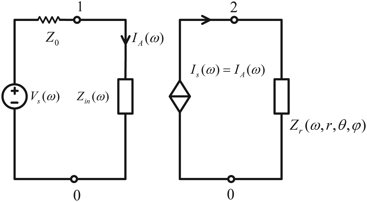
where r is a vector directing the point P(r, θ, φ). A circuit description of a transmitting antenna is shown in Fig. 1, where V s(ω) is the voltage source, Z 0 is the internal resistance of the voltage source, which is normally taken to be 50 Ω. Z inZ in is the input impedance of the antenna. I s(ω)is a controlled current source, which is determined by the current I A(ω). The frequency response of the impedance Z r(ω, r, θ, φ) is determined by the radiation fields E rad(r) excited by a constant voltage source V s(ω) = 1 placed at the feeding part of the antenna. The impedance value of Z r(ω, r, θ, φ) varies with the observation point P(r, θ, φ). The left part of the circuit is to calculate the input current I A(ω), whereas the right part of the circuit is to calculate the radiation fields E rad(r). Both of them are connected by the current-controlled current source. It is obvious that the circuit is a linear time-invariant system, as a result, the value of the radiation fields excited by an arbitrary voltage source V s(ω) can be calculated by the voltage value of the impedance Z r(ω, r, θ, φ).

Fig. 1. Circuit description of a transmitting antenna.
The above transmitting antenna circuit is established in the FD, which cannot be used in the TD analysis. In order to study the temporal behaviors of the radiation fields excited by a TD signal, a SPICE circuit is developed to achieve this purpose. It is often preferred to have a simple and accurate lumped component equivalent circuit, which is composed of a set of RLC components that has a frequency impedance function equivalent to the origin circuit.
In general, the input impedance Z in(ω) and the impedance Z r(ω) cannot be directly converted to RLC circuits, because their frequency responses are always nonlinear. However, if the input impedance Z in and the impedance Z r(ω, r, θ, φ) are approximated by rational functions, they can easily be converted to RLC circuits from the knowledge of the location of the residues and poles. A rational function for synthesizing the input impedance Z in or the impedance Z r is given by [Reference Antonini11]:
 $$Fp\lpar s\rpar =\sum\limits_{i=1}^n F{p_i}\lpar s\rpar =\sum\limits_{i=1}^n \left({\displaystyle{{re{s_{i1}}} \over {s - {p_{i1}}}}+\displaystyle{{re{s_{i2}}} \over {s - {p_{i2}}}}} \right)\comma$$
where (res i1, res i2) and (p i1, p i2) are pairs of residues and poles, respectively. One way of extracting the residues and poles from the rational function is to use the method of vector fitting (VF) [Reference Gustavsen and Semlyen12]. This method is based on iteratively relocating the poles and does not directly solve linear equations, whose condition number is highly ill-conditional.
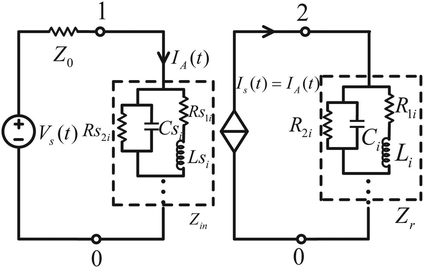
In (2), the rational function is composed of n parts, each part can be synthesized by a RLC circuit represented by Rs i1, Rs i2, C i, and L i. As a result, the whole rational function can be modeled by a series of RLC circuits, as shown in Fig. 2. The detailed procedures are given in literature [Reference Antonini11].

Fig. 2. A circuit topology of a rational function.
A SPICE model of a transmitting antenna is shown in Fig. 3, where the antenna impedance Z in(ω) is modeled by a series of RLC circuits represented by Rs 1i, Rs 2i, Cs i, and Ls i. The impedance Z r(ω) is also modeled by a series of RLC circuits represented by R 1i, R 2i, C i, and L i. V s(t) refers to the TD voltage source, and I s(t) refers to the TD current controlled current source, which is controlled by the current I A(t).

Fig. 3. SPICE model of a transmitting antenna.
When the antenna is excited by an arbitrary signal, the value of the radiation fields at the observation point P(r, θ, φ) can be obtained by measuring the voltage value between nodes 2 and 0, as shown in Fig. 3.
The scale of the model is determined by the order n of the rational function in (2), which is related to the modeling frequency range, modeling complexity, and modeling accuracy of the antenna. The accuracy of the model is restricted to the accuracy of the input impedance and radiation fields of the antenna, any approximations made in calculating these two parameters would result in some discrepancies.
Researchers normally want to get the input impedance and radiation fields of an antenna by analytical formulas. For most antennas, however, it is difficult to obtain the analytical formulas of the input impedances and radiation fields. As a result, one can obtain these parameters by measurements or by full-wave analyses.
III. NUMERICAL RESULTS
In this section, the proposed SPICE model of a transmitting antenna is verified by two examples. A dipole antenna and a rectangular microstrip antenna are analyzed by analytical formulas and modeled using the proposed method. The modeling frequency ranges of the two antennas are from 200 MHz to 5.5 GHz in which electronic systems are much more vulnerable to be damaged or upset [Reference Giri and Tesche13].
The results obtained by those models are validated by comparison with those using the software CST [14]. The antenna simulation models in CST are excited by an ideal voltage source, the TD waveform of which is taken to be the same with that in the SPICE model. A field probe placed in the far-field is to detect the electric field emitted from the antenna. As a result, the field strength at the observation point can be obtained after performing the transient analysis in CST.
A) Dipole antenna
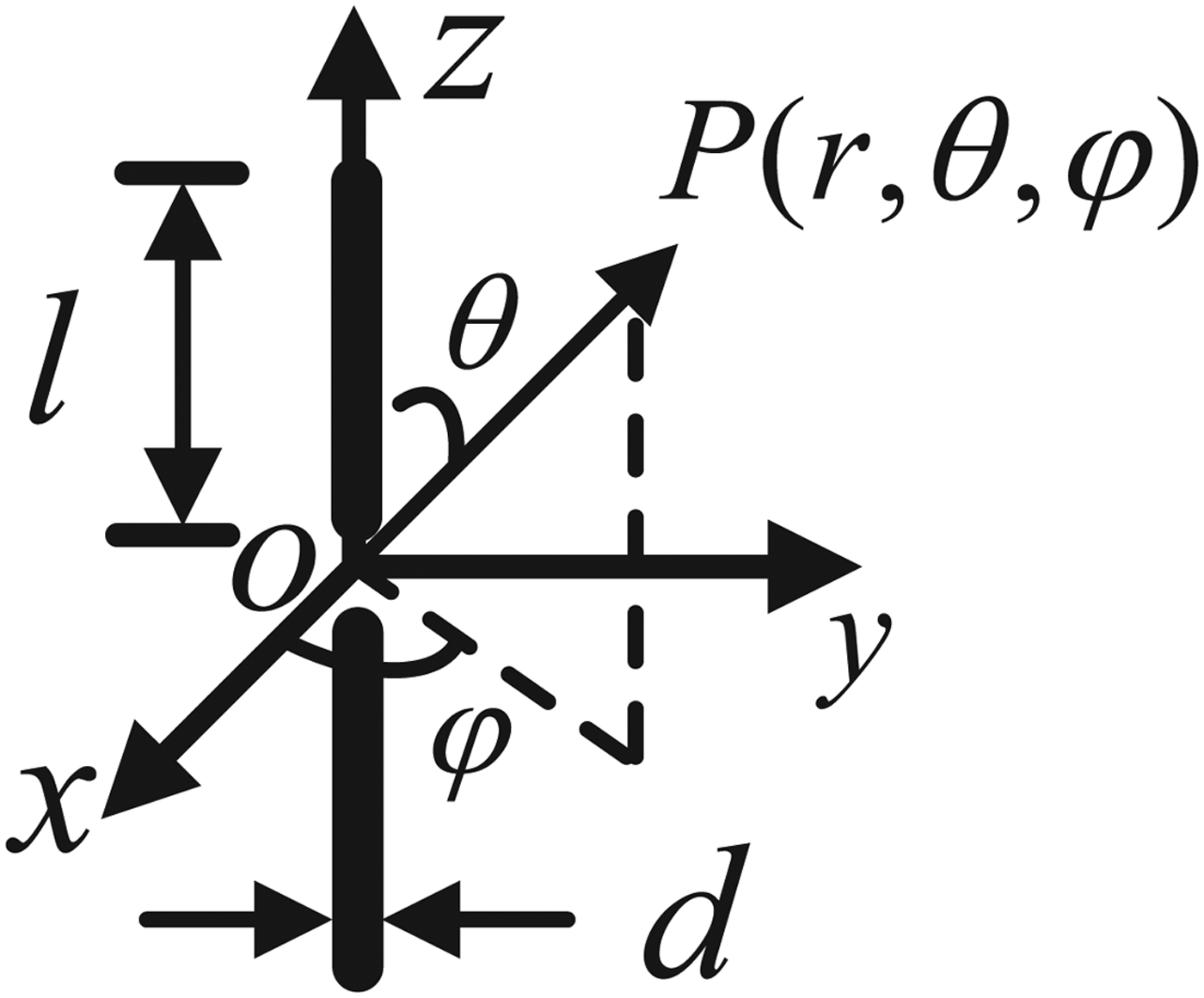
Figure 4 depicts the geometry of a dipole antenna and a reference Cartesian coordinate system of (x, y, z), whose origin coincides with the geometric center of the dipole. l refers to the length of one rod, d refers to its diameter, and (θ, φ) refers to the radiation angle toward the observation point P(r, θ, φ).

Fig. 4. Geometry of a dipole antenna.
In order to obtain a SPICE circuit of the dipole for transmitting, the current distribution Ĩ(z, ω) on the dipole is found when the dipole is excited by a constant voltage source V s(ω) = 1. Then, the input impedance of the dipole can be calculated as follows [Reference Benalla and Gupta15]:
 $${Z_{in}}=\displaystyle{{{V_s}\lpar \omega \rpar } \over {\tilde I\lpar 0\comma \; \omega \rpar }}=\displaystyle{{{\eta _0}\Omega } \over {16jkl\pi \sum\limits_{n=0}^\infty {\textstyle{1 \over {\mathop {\left({\mathop {\hat \sigma }\nolimits_{2n+1}+2jkl} \right)}\nolimits^2+\mathop {\hat \omega }\nolimits_{2n+1}^2 }}}}}\comma$$
in which
where η0 is the free-space intrinsic impedance, k is the free-space wavenumber.
The radiation fields are calculated by integrating the current over the antenna
where λ0 is the free-space wavelength.
Finally, the SPICE circuit of the dipole for receiving can be obtained by using the procedures shown in the previous section.
The radiation fields of the dipole are calculated by the proposed model in the following. Consider a dipole antenna of l = 37.5 mm (resonate at 2 GHz) and d = 1 mm. The antenna is excited by a Gaussian-modulated sinusoidal pulse whose TD behavior is given by:
where f 0 refers to the center frequency, τ refers to the pulse duration, and t 0 refers to the rising time. Parameters of the pulse are chosen as follows:
 $$\eqalign{{f_0}& =2\; {\rm GHz\comma \; } \cr {t_0}& =2\; {\rm ns\comma \; } \cr \tau& =1.}$$
Figure 5 shows the z-components of the radiation electric fields when the observation points (r, θ, φ) are (0.5 m, 90°, 0°) and (0.5 m, 60°, 0°). The results obtained by the proposed model agree well with those obtained by the software CST.

Fig. 5. Radiation fields of the dipole antenna: (a) (r, θ, φ) = (0.5 m, 90°, 0°). (b) (r, θ, φ) = (0.5 m, 60°, 0°).
B) Rectangular microstrip antenna
Many methods are developed to analyze microstrip antennas, such as the transmission line method [Reference Munson16], cavity model (CM) [Reference Carver and Mink17], integral equation method, and Green's function approach [Reference Mosig and Gardiol18, Reference Mosig and Gardiol19]. In this paper, the CM is used to analyze the microstrip antenna.
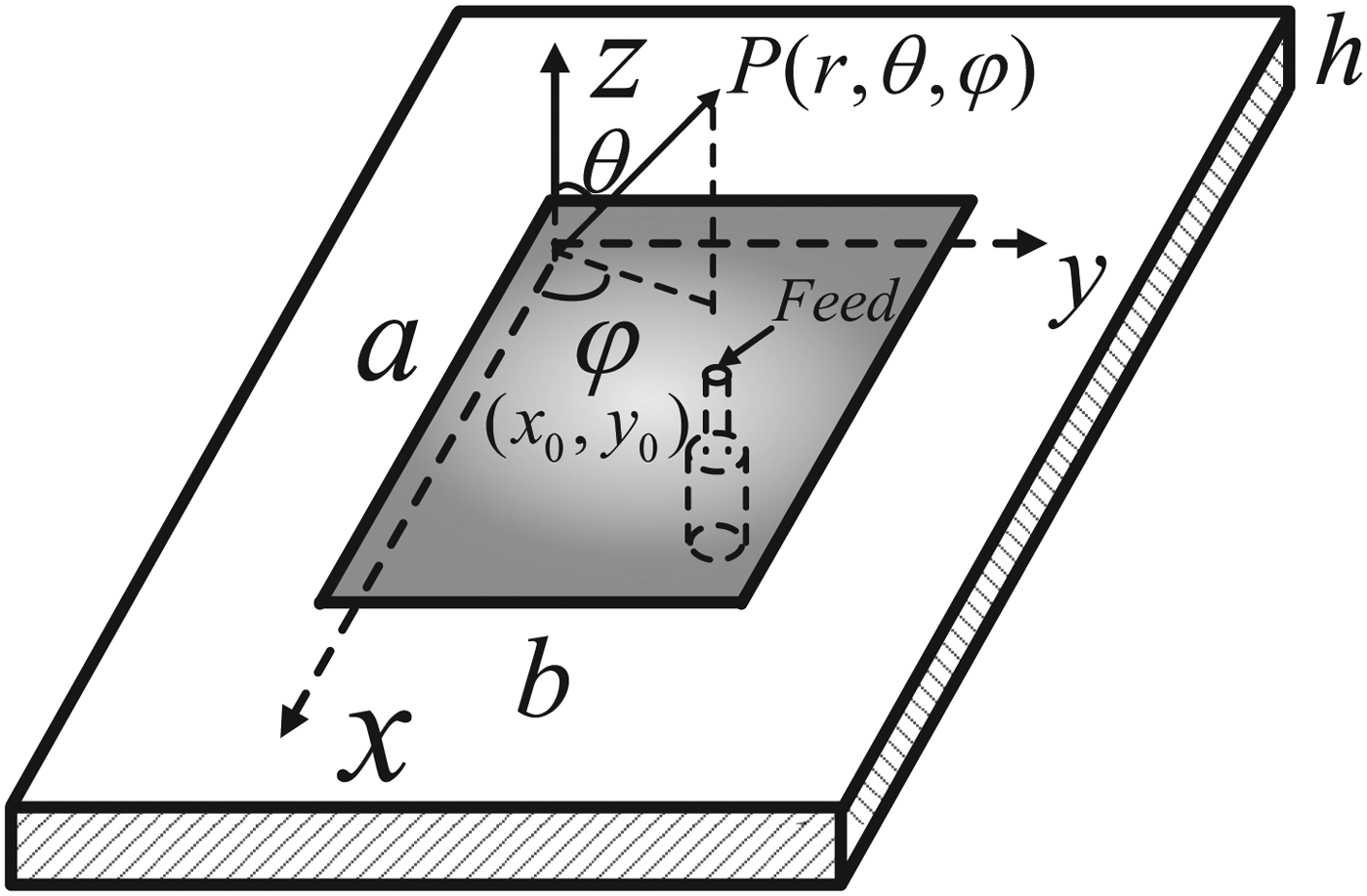
The geometry of a rectangular microstrip antenna (a × b × h) fed by a coaxial probe at (x 0, y 0) over an infinite ground is shown in Fig. 6. The substrate has a loss tangent of tanδ and a relative dielectric constant of εr.

Fig. 6. Geometry of a microstrip antenna.
The input impedance of the microstrip antenna is [Reference Carver and Mink17]:
in which Z is calculated by the ratio of the voltage and the current at the feed:
 $$Z=- j{\eta _0}kh\displaystyle{{{\delta _{0m}}{\delta _{0n}}} \over {ab}}\sum\limits_{m\;=\;0}^\infty {\sum\limits_{n\;=\;0}^\infty {\displaystyle{{\mathop {cos}\nolimits^2 {\textstyle{{m\pi {x_0}} \over a}}\mathop {cos}\nolimits^2 {\textstyle{{n\pi {y_0}} \over b}}} \over {k_{eff}^2 - k_{mn}^2 }}{G_{mn}}} }\comma$$
and X p is the inductance of the probe effect:
G mn refers to the current distribution on the coaxial fed probe, δ0g = 1, when g = 0 and δ0g = 2, when g ≠ 0, g stands for m or n, λ is the wavelength in the substrate, k eff is the effective wavenumber given by [Reference Carver and Mink17]:
 $${k_{eff}}={k_0}\sqrt {{\varepsilon _r}\left[{1 - j\left({tan\delta+\displaystyle{1 \over {{Q_r}}}+\displaystyle{1 \over {{Q_{sw}}}}} \right)} \right]}\comma$$
where Q r and Q sw refer to the radiation and surface wave losses, respectively.
The radiation fields of the microstrip can be calculated by integrating the magnetic currents on its edges, given by [Reference Lo, Solomon and Richards20]:
 $$\left\{{\matrix{ {{E_\theta }=\displaystyle{{4kh{B_{mn}}} \over {{{\rm \lambda }_0}r}}{e^{ - jkr}}{e^{j\left({{\textstyle{{u+m\pi } \over 2}}+{\textstyle{{v+n\pi } \over 2}}} \right)}}sin\displaystyle{{u+m\pi } \over 2}sin\displaystyle{{v+n\pi } \over 2}} \cr {\quad \left[{\displaystyle{{{a^2}} \over {{u^2} - \mathop {\lpar m\pi \rpar }\nolimits^2 }}+\displaystyle{{{b^2}} \over {{v^2} - \mathop {\lpar n\pi \rpar }\nolimits^2 }}} \right]sin\theta \;sin\varphi \;cos\varphi\comma \; } \cr {{E_\varphi }=\displaystyle{{4kh{B_{mn}}} \over {{\lambda _0}r}}{e^{ - jkr}}{e^{j\left({{\textstyle{{u+m\pi } \over 2}}+{\textstyle{{v+n\pi } \over 2}}} \right)}}sin\displaystyle{{u+m\pi } \over 2}sin\displaystyle{{v+n\pi } \over 2}} \cr {\left[{\displaystyle{{{a^2}\mathop {cos}\nolimits^2 \varphi } \over {{u^2} - \mathop {\lpar m\pi \rpar }\nolimits^2 }} - \displaystyle{{{b^2}\mathop {sin}\nolimits^2 \varphi } \over {{v^2} - \mathop {\lpar n\pi \rpar }\nolimits^2 }}} \right]sin\theta \;cos\theta\comma \; } \cr } } \right.$$
in which
where B mn refers to the coefficient of the TM mn mode of the antenna, λ0 refers to the free-space wavelength, and r refers to the distance from the observation point to the origin.
Using the procedures in the previous section, the SPICE circuit of the rectangular microstrip antenna can be obtained. Next, the radiation fields are calculated by the proposed model.
Consider a rectangular microstrip antenna which has the dimensions of a × b × h = 46 mm × 31 mm × 1 mm. The location of the fed probe is (x 0, y 0) = (23 mm, 25.5 mm). The relative dielectric constant and loss tangent of the substrate are 2.25 and 0.0018, respectively.
The antenna is also excited by a Gaussian-modulated sinusoidal pulse as shown in (11), the parameters are taken to be
 $$\eqalign{{f_0}& =3\; {\rm GHz\comma \; } \cr {t_0}& =2\; {\rm ns\comma \; } \cr \tau& =1.}$$
Figure 7 shows the y-component of the radiating fields when the observation points are (0.5 m, 0°, 0°) and (0.5 m, 30°, 50°).

Fig. 7. Radiation fields of the rectangular microstrip antenna: (a) (r, θ, φ) = (0.5 m, 0°, 0°). (b) (r, θ, φ) = (0.5 m, 30°, 50°).
The results obtained the proposed model and the software CST match very well in these two cases.
C) Analysis of fidelity
The fidelity of the radiation fields is calculated to demonstrate the accuracy and correctness of the proposed model, given by [Reference Gao and Du10]:
 $$F=\vint_{{T_{stop}}}^{{T_{start}}} \displaystyle{{{f_{spice}}\lpar t\rpar } \over {\sqrt {\vint_{{T_{stop}}}^{{T_{start}}} {{\left\vert {{f_{spice}}\lpar t\rpar } \right\vert }^2}dt} }}\displaystyle{{{f_{cst}}\lpar t\rpar } \over {\sqrt {\vint_{{T_{stop}}}^{{T_{start}}} {{\left\vert {{f_{cst}}\lpar t\rpar } \right\vert }^2}dt} }}dt\comma$$
 $$REE=\displaystyle{1 \over {\left({{T_{stop}} - {T_{start}}} \right)}}\displaystyle{{\vint_{{T_{stop}}}^{{T_{start}}} {{\left\vert {{f_{spice}}\lpar t\rpar - {f_{cst}}\lpar t\rpar } \right\vert }^2}dt} \over {\vint_{{T_{stop}}}^{{T_{start}}} {{\left\vert {{f_{cst}}\lpar t\rpar } \right\vert }^2}dt}}\comma$$
where F in (20) refers to the correlation coefficient, and REE in (21) refers to the relative energy error. f spice and f cst are the voltage computed by the proposed model and the software CST, respectively, and T start and T stop are the starting time and stop time of the voltage, respectively. F is adopted to measure the TD waveform shape errors of the results, while REE is adopted to measure the energy errors of the results when they are compared with the reference solutions obtained by the software CST.
Table 1 shows the correlation coefficients and REEs when T start = 0 ns and T stop = 8 ns. The correlation coefficients are close to 1 and REEs are less than 6%, which indicate that the results given by the proposed model are accurate and correct.
Table 1. Comparison between the SPICE model and the software CST.

IV. CONCLUSIONS
In this paper, a SPICE model of a transmitting antenna is proposed to calculate its radiation fields. The proposed model is verified by two examples. A dipole antenna and a rectangular microstrip antenna are analyzed by analytical formulas, their SPICE models for transmitting are established using the proposed method. The radiation fields obtained by the proposed models agree well with those reference solutions based on the software CST. Besides, the fidelity of the results is calculated to demonstrate the accuracy and correctness of the proposed model.
The proposed model allows one to obtain FD radiation fields for a range of frequencies in which the model is valid, or to obtain the TD radiation fields for an arbitrary excitation TD signal, the spectrum of which should be within the modeling range.
Using this model, the radiation characteristics of an antenna can be analyzed. Besides, the model can be a part of a complete system-level EMC simulation.
ACKNOWLEDGEMENTS
This work was supported in part by the National Basic Research Program of China under Grant no. 2009CB320205, in part by the National Science and Technology Major Project of the Ministry of Science and Technology of China under Grant no. 2012ZX03003002-004, in part by the National Natural Science Foundation of China under Grant nos 61371010 and 60971005, in part by the National High Technology Research and Development Program of China (863 Program) under Grant nos. 2007AA01Z284 and 2006AA01Z265, and in part by the Project 9140A33020411JW27.
 Xiang Gao received the B.E. degree in Electronic Science and Technology from the University of Electronic Science and Technology of China, Chengdu, China, in 2011. He is currently working toward the Ph.D. in Tsinghua University, Beijing, China. His research interests include antenna modeling and electromagnetic compatibility/electromagnetic interference.
 Zhengwei Du was born in Sichuan Province, China, on August 21, 1971. He received the B.Sc., M.Sc., and Ph.D. degrees in Engineering from the University of Electronic Science and Technology of China, Chengdu, China, in 1992, 1995, and 1998, respectively. Since 1998, he has been with Tsinghua University, Beijing, China, as a Postdoctoral Fellow (February 1998–October 1999), Research Assistant (November 1999–July 2000), Associate Professor (August 2000–December 2006), and currently, Full Professor. His main research interests include ultra-wideband/short-pulse electromagnetic, antenna, propagation, analysis of microwave/millimeter wave planar structures, photonic bandgap (electromagnetic bandgap) circuits, and electromagnetic compatibility/electromagnetic interference (EMC/EMI).


