I. INTRODUCTION
Imaging systems in the millimeter- and microwave regimes are attracting particular attention due to their use in security, medical, and non-destructive-testing systems [Reference Ahmed, Schiessl and Schmidt1–Reference Zhuge and Yarovoy4]. Current advances in the semiconductor technology have made integrated radiofrequency (RF) components at millimeter-wave frequencies available in high quantity [Reference Tiebout5], allowing for high integration levels and utilizing digital beamforming. An overview of these advanced imaging systems and reconstruction methods is given in [Reference Ahmed, Schiessl, Gumbmann, Tiebout, Methfessel and Schmidt6].
To benefit from the high transceiver count required for digital beamforming in multistatic sparse arrays, the cost aspects, space, and integration efficiency also of the antenna array have to be ensured. This becomes much more difficult at millimeter-wave frequencies and for radar applications, where radiation characteristics and the achievable resolution due to bandwidth and the short wavelength are challenging aspects [Reference Ahmed, Schiessl and Schmidt1]. Even more sophisticated systems using sparse periodic arrays with reduced number of antennas rely on appropriately designed antennas [Reference Zhuge and Yarovoy4, Reference Gumbmann and Schmidt7], especially if polarization is used for further examination [Reference Sheen, McMakin, Lechelt, Griffin, Appleby and Wikner3, Reference Cenanovic, Gumbmann and Schmidt8].
Using a planar, balanced-fed antenna is the first step to an easy integration with differential interfaced monolithic microwave integrated circuits (MMICs) [Reference Tiebout5]. In [Reference Methfessel and Schmidt9, Reference Methfessel and Schmidt10], the concept of a patch-excited horn antenna, hereinafter referred to as the hybrid antenna, is introduced. For achieving a higher and less extensive integration level, this design has to be reduced in size and complexity, while maintaining the performance of the antenna. Challenges are the feeding structure and the performance in proximity to other antennas. After introducing the concept of the antenna and array in Section II, the relevant design improvements of the antenna are presented in Section III. Continuing with the optimization of the structure in Section IV, simulated and measured results of the antennas and arrays are presented and discussed in Section V.
II. ANTENNA AND ARRAY CONCEPT
A) Imaging systems and arrays
Different versions of the introduced hybrid antennas are currently used in two imaging systems, both operating in a stepped frequency continuous wave (SFCW) mode from 70 to 80 GHz, achieving a resolution of 2 mm in cross-range and approximately 10 mm in range for objects at a distance of about 1 m. They are based on planar multistatic sparse-array designs with distinct geometries and options for different applications, as can be seen in Fig. 1.

Fig. 1. Schematic representation of two multistatic sparse arrays. (a) Part of 2D-array [1], (b) polarimetric 1D-array [8].
1) TWO-DIMENSIONAL (2D) ARRAY
The first system utilizes the digital-beamforming (DBF) technique in a 2D-array [Reference Ahmed, Schiessl and Schmidt1, Reference Schiessl, Genghammer, Ahmed and Schmidt11, Reference Schiessl, Juenemann and Schmidt12] for real-time image acquisition in personnel screening. It consists of 32 identical front-end modules (called clusters), each having 94 transmitting (Tx), and 94 receiving (Rx) channels aligned vertically and horizontally, respectively (Fig. 1(a)). The antennas are placed in a quadratic contour with a spacing of 3 mm, and are connected to 24 millimeter-wave MMICs with four channels each [Reference Tiebout5] by short differential transmission lines. This sums up into a 2 m × 1 m array with over 6000 channels.
2) POLARIMETRIC 1D-ARRAY
The second imaging system combines synthetic aperture radar (SAR) and DBF into a hybrid concept, by moving a linear polarized, sparse periodic 1D linear transmit and receive array perpendicularly to the array coordinates [Reference Gumbmann and Schmidt7]. This concept allows for adaptation of the imaging aperture to the measurement object (e.g. cylindrical for personnel screening and linear for non-destructive testing in a production line), while reducing the required number of channels. As extension, a second orthogonal polarized 1D linear array is added in the system for ellipsometry and automated threat detection [Reference Cenanovic, Gumbmann and Schmidt8, Reference Cenanovic, Gumbmann and Schmidt13]. By dividing the whole array into several Tx- and Rx-clusters including MMICs (Fig. 1(b)), a high modularity and adaptability is achieved. The resulting system consists of three vertically and three horizontally polarized Tx-clusters with 15 antennas each, separated by 3 mm and connected to four MMICs. One Rx-cluster contains four antennas of each polarization, separated by 27 mm × 3 mm, respectively, together with two MMICs. This results in 90 Tx-channels and 48 Rx-channels in six Rx-clusters with an overall aperture length of 60 cm, capable of scanning objects with two polarizations.
Additional claims of the closely related imaging systems with respect to the antenna design are the dynamic range of 40 dB for adequate image quality, and a differential impedance of 100 Ω at the MMIC. The former translates to an acceptable crosstalk of −40 dB, which is most critical between neighboring antenna elements. Since the behavior of the MMIC regarding the reflection of the common mode is unknown, a low-mode conversion between the differential and the unwanted common mode on the feeding structure has to be ensured.
B) Antennas
The cross-section of the antennas presented in this paper is shown in Fig. 2 as introduced in [Reference Methfessel and Schmidt9]. From top to bottom the antenna consists of a horn, forming the pattern, and the three radiating elements: patch, aperture slots, and balanced-fed dipole. The multilayer is built by laminates and prepregs of the RO4350B substrate system from Rogers Corporation. The whole radiating structure is surrounded by a substrate-integrated cavity as an extension of the horn, with vias from top to bottom ground except the one at the feeding structure. This cavity does not contribute to the radiation, but avoids backward radiation through the substrate as well as the excitation of the substrate or parallel plate waves, and isolates the feeding structure from the radiators.
Fig. 2. Cross-section of the patch-excited horn antenna (hybrid antenna).
Dense packing and feeding is required in building a 2D array for digital-beamforming; therefore, care has to be taken in aligning the polarization of the transmitter and receiver antennas [Reference Schiessl, Juenemann and Schmidt12]. Two possible solutions with respect to the aforementioned arrays are shown in the next subsections.
1) ORIGINAL 45° ANTENNA
One solution is the 45° rotated antenna introduced in [Reference Methfessel and Schmidt9], advanced with a narrowed cavity. The top view is shown in Fig. 3(a) such as for a corner of the quadratic contoured array in one cluster, as described in Section IIA-1 and [Reference Ahmed, Schiessl and Schmidt1]. The antenna used here features horizontally or vertically oriented and centric feeds while being aligned in polarization. The cavity in general and the tilted feed have some negative effects on the antenna's performance and are analyzed in the next section.
Fig. 3. Arrays with variably rotated hybrid antennas and feed lines. (a) Corner of the quadratic contoured 2D-array with original antenna and narrowed cavity. (b) Polarimetric line in 1D-array with optimized antennas and short-circuited cavity.
2) OPTIMIZED 0° AND 90° ANTENNA
Another solution is shown in Fig. 3(b), where the optimized antennas are aligned in a pattern comparable to the polarimetric 1D-array described in Section IIA-2 and [Reference Gumbmann and Schmidt7, Reference Cenanovic, Gumbmann and Schmidt8, Reference Cenanovic, Gumbmann and Schmidt13]. Here two different antennas with either 0° or 90° polarization are used, as a result of the improvements of the next sections. This setup is advantageous for polarimetric measurements, since the two polarization states are orthogonal to the incidence plane of the electromagnetic waves on the measured scene [Reference Cenanovic, Gumbmann and Schmidt8]. However, the 90° polarized antenna suffers from the needed bend in the feeding structure, which has to be compensated for true differential signaling with reduced mode conversion as stated earlier. Possible compensation structures are discussed in [Reference Juenemann, Zielska, Schiessl, Methfessel and Schmidt14], together with another adapted 45° antenna and the used array.
III. IMPROVEMENTS
A) Feed line overlap
In a first step, the feeding structure of the original antenna was analyzed and optimized because of its coupling to the aperture slots and the dipole. This is because of the 45° rotated antenna structure, as can be seen in Fig. 4 by slicing the 3D-model at the aperture slot. In order to reduce field distortion and unwanted radiation, the lines close to the antenna are maintained straight. By further adding a compensation structure for the differential bend like in Fig. 3(b), using for example the meander line discussed in [Reference Burford, Levin and Kazmierski15], the antenna can be rotated into a 0°, 45°, and even 90° polarization state, as required by the array. As a drawback, the occurring but unwanted cavity resonance is particularly excited.
Fig. 4. Magnetic fields, feed line coupling to aperture slots and dipole.
B) Cavity resonances
As stated in [Reference Methfessel and Schmidt9], the resonant frequency of the embedded cavity is lower than the original design frequency of 79 GHz by choosing a wider diameter, which is the dominant lateral dimension. The problematic, highly reflective resonance becomes visible in the TM110 mode, which is unfortunately independent of the substrate height [Reference Rizzi16] and is shown in Fig. 5(a) for a simplified antenna. In order to reduce the size of the antenna, this cavity diameter has to be reduced without shifting the cavity resonance in the operational band, as this causes degradation in efficiency and return loss. A possible degree of freedom is the permittivity of the used substrates, since a higher value scales the structure down. However, manufacturing specifications limit the usable dielectric materials and the smallest realizable structure during the etching process. Additionally, the relationship between all resonant frequencies remains the same, by not shifting the cavity resonance. Another solution would be an even smaller diameter so that the resonant frequency is above the antenna frequency, but this would lead to very small distances in the antenna structure.
Fig. 5. Suppression of cavity resonances. (a) Magnetic field of the excited resonance, (b) short-circuiting vias in the cavity.
The method of choice are two short-circuiting vias introduced in the multilayer substrate, as can be seen in Fig. 5(b). These vias only influence the cavity resonance without disturbing the antenna too much. Simulated results of the reflection coefficient and the radiation efficiency of the simplified antenna, having a smaller cavity, which emphasizes the resonance, approve this concept (Fig. 6). Without additional vias, the reflection coefficient increases at the cavity's resonance frequency of 77 GHz, while the radiation efficiency decreases. This demonstrates the double impact of the unwanted cavity resonance on the antenna performance and provides the reason for further optimization of the antenna structure.
Fig. 6. Simulated reflection coefficient (solid lines) and radiation efficiency (dashed lines) of the antenna without (blue) and with (red) short-circuiting vias.
IV. OPTIMIZATION
After creating the basis for size-reduction and suppression of cavity resonances, the geometry of the antenna structure was optimized. Objectives were the radiation pattern parameters like half-power-beamwidth in both planes, polarization ratio, and phase in addition to a high radiation efficiency and low reflection coefficient over a wide frequency range. The final optimized antennas are shown in Figs 3(b) and 7 for the two polarization states (0° and 90° with compensated bend).
As one result the stability of the phase center over frequency is presented. This quantity is important in imaging systems, as it directly influences the quality of the image reconstruction. Figure 8 shows the three simulated coordinates for both polarization states of the optimized antenna with respect to the polarization plane, with the origin of the coordinate system in the center of the aperture of the cylindrical horn (see Fig. 2). In the z-direction (along horn dimension), only minor variations of the phase center can be reported, while the x- and y-positions are nearly independent from frequency. The error is smaller than 2% when expressed in wavelengths.
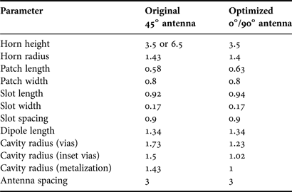
The resulting dimensions of the optimized antennas, which are independent of the polarization state, are listed in Table 1, together with the starting values of the original antenna with an orientation of 45°. As can be seen from the three changing radii of the cavity vias and metalization, the required footprint of the optimized antenna on the substrate is reduced by approximately 45%. The radius of the cylindrical horn decreases only slightly, since the cutoff-frequency of this, for example, circular waveguide is related to the lowest operational frequency of 70 GHz.
Table 1. Antenna dimensions in mm.
A tolerance analysis was made by means of a parameter sweep in the main geometric dimensions, determining the deviation in reflection coefficient, or radiation parameters. Additionally, a possible layer offset was studied, which can occur during manufacturing. This can be seen in Fig. 7, where the vias as a showcase are shifted by 30 µm. The expected tolerances of the photolithographic and milling manufacturing process are specified in a range from approximately 20 µm for etched structures, up to a maximum of 80 µm for the alignment of vias and structures, especially when on different laminates. Depending on the density of the etched structures, the thickness of the prepreg can vary between 5 and 15%, which has a greater influence together with the differing permittivity of the used dielectrics. In all, only minor deviations of the desired properties are examined, resulting in few percent error of the reflection coefficient with respect to bandwidth and magnitude, except of the substrate parameters. Radiation efficiency and gain are generally robust toward manufacturing tolerances.
Fig. 7. Pictures of the manufactured multilayer substrate: 30 µm displacement of via. Top view with patch and via cavity. Feeding layer with 0° and 90° dipole, differential stripline, and meander line.
V. DISCUSSION OF RESULTS
The simulations in this paper are carried out with the 3D EM simulation software CST MICROWAVE STUDIO®. Since the parameters of the used laminates and prepregs of the RO4350B substrate system are only given at 10 GHz with two distinct values for design and process, a characterization of the material parameters was performed prior to all simulations. Using a measurement system by means of an open resonator at 77 GHz [Reference Kilian, Weinzierl and Schmidt17], a relative permittivity ε r of 3.8–3.9 at 77 GHz together with a dissipation factor tanδ of 0.0045 is determined. Dielectric and also ohmic losses are included in the simulation, not accounting for surface roughness or deviations in the conductivity.
In order to measure the balanced-fed antenna, an adapted transition from WR-12 standard waveguide to 100 Ω differential stripline is utilized [Reference Methfessel and Schmidt10], together with two frequency converters ZVA-Z90E and a four-port network analyzer ZVA24 by Rohde & Schwarz, as well as a far-field measurement system, capable of rotating the antenna under test in elevation and azimuth. Owing to the lack of appropriate true differential transitions and calibration standards at millimeter-wave frequencies, the measured results suffer from the influence of the transition and show significant ripple.
A) Scattering parameter
Measured and simulated reflection coefficients are shown in Fig. 9 for both optimized antennas and agree in principle. For the 0° antenna in Fig. 9(a) the simulated bandwidth of 17% is clearly reflected in the measurement data. As can be seen in the results of the 90° antenna in Fig. 9(b), the overlying ripple is caused by multiple reflections and resonances on the feeding line due to considerable and repeated conversion between the differential and the unwanted common mode. The simulated mode-conversion of about −18 to −25 dB for the 90° antenna with feed line bend has to be compared with −60 dB (not shown in Fig. 9(a)) for the 0° antenna without bend, proving the need of compensating structures, which are addressed in [Reference Juenemann, Zielska, Schiessl, Methfessel and Schmidt14].
Fig. 8. Phase center of the 0° (red) and 90° (blue) antenna in x (solid lines), y (dotted lines), and z (dashed lines).
Fig. 9. Simulated (dashed lines) and measured (solid lines) reflection coefficient of both optimized antennas and simulated conversion (solid green line) between differential and common mode of the 90° antenna. (a) Optimized 0° antenna without bend, (b) optimized 90° antenna with bend.
In the proposed arrays, antenna elements are in close proximity to each other and suffer mainly from crosstalk. This is especially critical in the quadratic contour of the 2D-array described in Section IIA-1, because the transmitting and receiving elements touch each other in the corners and introduce a certain level of cross-coupling. Since a dynamic range of 40 dB is required for adequate image quality, even strong reflected signals can be hidden by a path loss of 64 dB for objects at 1 m distance and the introduced crosstalk [Reference Schiessl, Genghammer, Ahmed and Schmidt11].
Simulated results of a four-element corner with the original 45° antennas are shown in Fig. 10, with the driven antennas 1 and 2 vertically, and the receiving antennas 3 and 4 horizontally aligned (see also Fig. 3(a)). The adjacent elements 2 and 3 exhibit the highest crosstalk of about −27 dB, which reduces to −35 dB by increasing the distance. These transmit–receive combinations cannot be calibrated thoroughly and have to be masked out for proper image reconstruction [Reference Ahmed, Schiessl and Schmidt1].
Fig. 10. Simulated cross-talk of a four-element corner with the original 45° antennas: reflection coefficient S 22 of antenna 2 (blue), and its cross-coupling to 1 (S 12 green), to 3 (S 32 red) and to 4 (S 42 cyan).
A little more relaxed in terms of cross-coupling is the polarimetric line array described in Sections IIA-2, since transmitting and receiving elements are clustered and separated from each other with only a few neighboring elements. Every antenna is shielded by cavity vias in the substrate and the horn on the surface; therefore coupling due to substrate, parallel plate, and surface waves are negligible. Stronger coupling occurs due to space waves and induced currents at the edges of the horn [Reference Balanis18]. In consequence and as shown in Fig. 11(a), adjacent optimized antenna elements (3 mm distance) of the same polarization show a measured cross-coupling of about −30 dB, independent of the orientation of the electric field vector (0° antennas are coupled in the E-plane, 90° antennas are coupled in the H-plane, as can be seen in Fig. 3(b) in vertical alignment). The measured cross-coupling of two adjacent antennas with orthogonal polarization (as seen in Fig. 3(b) in horizontal alignment) is about 10 dB lower.
Fig. 11. Measured cross-coupling between the optimized antenna elements in the polarimetric line array: between 0° (red), between 90° (blue), between 0° and 90° (green) antennas. (a) Adjacent antenna elements and (b) next but one antenna elements.
With a separation of one antenna element (in total 6 mm distance), the cross-coupling drops by approximately 5 dB for the 0° antenna, and by approximately 10 dB for the 90° antenna (Fig. 11(b)). At larger distances, the coupling in the E-plane is stronger than in the H-plane [Reference Balanis18]. In general, additional edges and holes, e.g. by screws in the lid with the horns, should be avoided to reduce cross-coupling due to induced currents.
B) Radiation characteristics
The radiation characteristics are measured using the three antenna method with two different horn antennas, corrected by the measured insertion loss of the transition. This is unfortunately only a guide value because of the inaccessible conversion of the differential into the common mode, introducing additional loss with multiple peaks over frequency. In Fig. 12, the simulated and measured gain of both antennas is presented, exhibiting a slightly smaller gain than calculated, about 5.5 dBi over the used frequency band. This is partly due to mutual coupling between the antenna elements, as well as higher ohmic loss in the structure, and by the aforementioned losses due to mode-conversion in the transition.
Fig. 12. Simulated (dashed lines) and measured (solid lines) gain: optimized 0° (red) and 90° (blue) antenna.
Another measure is the risen cross-polarized component in the presence of mutual coupling, especially outside of the main E- and H-planes in cuts at φ = 45°. This is shown in the simulated radiation pattern of the optimized 0° antenna in Fig. 13 at 75 GHz.
Fig. 13. Simulated directivity of the optimized 0° antenna at 75 GHz: cuts at φ = 0° (blue), 45° (red) and 90° (green) for co-(dashed) and cross-polarization (solid) with mutual coupling, compared to ideal cross-polarization at 45° without mutual coupling.
Polarization purity is slightly degraded for polarimetric measurements, when the observed objects appear at wider viewing angles, and yields a value of about 15 dB at ϑ = 45° and 22 dB at ϑ = 25°.
In addition, measured sphere patterns for both optimized antennas are shown in Figs 14 and 15 for co-polarized amplitude and phase as well as cross-polarized amplitude at 75 GHz. Owing to moving constraints of the far-field measurement setup, angles higher than 60° could not be achieved. Secondly, the patterns show some interference ripples because of reflections at the measurement hardware. As explained previously, both patterns are almost equal with a beamwidth of about 50° and a low level of cross-polarization in all directions.
Fig. 14. Measured pattern of the optimized 0° antenna structure at 75 GHz. (a) Co-polarized amplitude, (b) cross-polarized amplitude, and (c) co-polarized phase.
Fig. 15. Measured pattern of the optimized 90° antenna structure at 75 GHz. (a) Co-polarized amplitude, (b) cross-polarized amplitude, and (c) co-polarized phase.
Important information for imaging systems and digital beamforming applications is the phase deviation over all viewing angles, in conjunction with the phase center. The phase plots of the patterns are quite flat with a nearly coincident apparent phase center in elevation and azimuth.
VI. CONCLUSION
With the request of size-reduction of millimeter-wave antennas in sparse periodic arrays for imaging systems with polarimetric measurement capabilities, possible solutions, and their implementation have been presented in this paper. The required footprint of the optimized antennas is reduced by approximately 45%, without changing the antenna's properties. Cavity-resonances can be effectively suppressed by introducing short-circuiting vias. The polarization of the antennas can be properly aligned with the array geometry by using compensated bends in the differential feeding structure. Simulated and measured results are in good agreement, yielding a bandwidth of 17% and an antenna gain of 5 dBi for the optimized antennas with two orthogonal polarizations. Both antennas show a symmetric radiation pattern with low cross-polarization and flat phase with a stable phase center. A tolerance analysis indicates an antenna design which is not very sensitive to manufacturing errors. The influence of mutual coupling has also been studied with respect to the used geometries of a sparse periodic 2D and 1D array. Higher cross-coupling occurs for adjacent elements in the 2D-array, which have to be masked out for proper image reconstruction. The degradation of polarization purity at neighboring elements in the polarimetric 1D-array is especially critical for objects at wider viewing angles and outside the main E- and H-planes.
ACKNOWLEDGEMENTS
The authors acknowledge the German Ministry of Research and Education BMBF for funding part of the presented activities. The authors also thank C. Evers and all colleagues at Rohde & Schwarz GmbH & Co. KG, Munich, Germany, for the collaboration work and providing manufacturing capacities.
Sebastian Methfessel received the Diploma degree in Electrical, Electronic and Communication Engineering from the University of Erlangen-Nuremberg, Erlangen, Germany in 2007. Since then he is a Research Associate at the Institute of Microwaves and Photonics at the University of Erlangen-Nuremberg, where he is currently working toward the Ph.D. degree. He has coauthored several conference and journal papers on millimeter- and microwave technology. His research interest is in the area of millimeter- and microwave technology, focusing on imaging systems, antennas and arrays, as well as measurement technology.
Lorenz-Peter Schmidt received the Diploma and Ph.D. degrees in Electrical Engineering from the Technical University of Aachen, Germany, in 1974 and 1979, respectively. In 1979, he became a Postdoctoral Fellow with the University of Texas, Austin. From 1980 to 1998, he was with AEG-Telefunken, Ulm, Germany (now CASSIDIAN), where he became the Head of the Corporate Advanced Millimeter-Wave Department. Since 1998, he has been a Full Professor and the Head of the Institute of Microwaves and Photonics, University of Erlangen-Nuremberg, Germany. His main research interests are in the field of millimeter-wave and terahertz components and antennas as well as active and passive high-resolution imaging systems. Dr. Schmidt is a member of VDE and a member of the German IEEE MTT/AP Chapter Commission. In 2003, he served as the EuMW General Chairman and in 2013 as the EuMC Chairman. In 2013, he received the Microwave Prize of the MTT Society.