Introduction
Polarization is one of the most essential and significant features of an antenna in modern wireless communication systems [Reference Balanis1]. Polarization of an antenna is the locus traced out by the tip of the electric field vector of the wave radiated or received by the antenna as a function of time. Polarization of an antenna is usually determined from the electric field orientation; it will be either linearly or circularly polarized (CP) [Reference Balanis1]. The orientation of the electromagnetic field radiated by a linearly polarized antenna lying in one plane, orthogonal to the direction of electromagnetic wave propagation. For example, a vertically polarized antenna can efficiently transmit and receive only a vertically polarized wave and vice versa, which is known as co – polarization [Reference Ludwig2]. Due to the reciprocity property of the antenna, the transmission and reception of the antenna are always similar. If a receiving antenna is vertically polarized and a transmitting antenna is horizontally polarized, then it is called cross-polarization [Reference Ludwig2], which incurs a huge signal loss. In circular polarization the antenna emits electromagnetic energy in a circular spiral pattern which covers horizontal, vertical, and all the planes in-between them. With circular polarization, the orientation of the transmitting and receiving antennas is irrelevant as the circular pattern of the transmitting and/or receiving antenna will always match with pattern of the incoming signal. Among other salient advantages of CP antennas are multipath rejection, which leads to signal interference in linear polarization, mitigation of fading effects and immunity against Faraday rotation effect, which make CP antennas somewhat indispensable components in modern wireless communication systems [Reference Ludwig2].
In the case of circular polarization, the orthogonal field components are almost of equal amplitude, spatially orthogonal and in phase quadrature. Thus the tip of the resultant electric field vector generates a circular locus while evolving in time.
In linear polarization, Fig. 1(a), the tip of the electric field vector oscillates along the same line, here along the x- or y-axes, thus tracing out a straight line.

Fig. 1. Electric field vector tracing (a) linear, (b) circular, and (c) elliptical polarizations [Reference Balanis1].
In the case of elliptical polarization, shown in Fig. 1(c), however, the quadrature-phase difference between the two field components is maintained, but the field components may not be of the same magnitude, as in circular polarization, shown in Fig. 1(b). So, circular polarization may be considered as a special case of elliptical polarization. Circular polarization is quantified by the axial ratio (AR) [Reference Balanis1], which is the ratio of the maximum and minimum semi-axes of the polarization ellipse and is given in decibels by:

from which it can be noticed that 1 ≤ AR < ∞. A pure circular polarization can be achieved when AR = 1 or 0 dB, which is difficult to achieve in practice. Therefore, a frequency range over which AR ≤ 3 dB is considered, and defined as

where, f 1 and f 2 are the boundary frequencies for AR ≤ 3 dB and fmin is the frequency of minimum value of AR. The polarization ellipse is shown in Fig. 2, where the major and the minor axes are shown. $E_{x_0}$ and $E_{y_0}$
 , mentioned in (1) are the maximum values of the electric field magnitude on these axes. For circular polarization, these values are equal. So, circular polarization is a special case of elliptical polarization. Also, it is seen from Fig. 2 that the orientation of the ellipse is defined by another parameter, the tilt angle (τ), which is the inclination of the major axis of the ellipse with respect to the vertical axis. OA and OB represent the major and minor axes of the polarization ellipse, respectively, while $E_{x_0}$
 and $E_{y_0}$
 represent the maximum magnitudes of the electric field along the x- and y-directions.
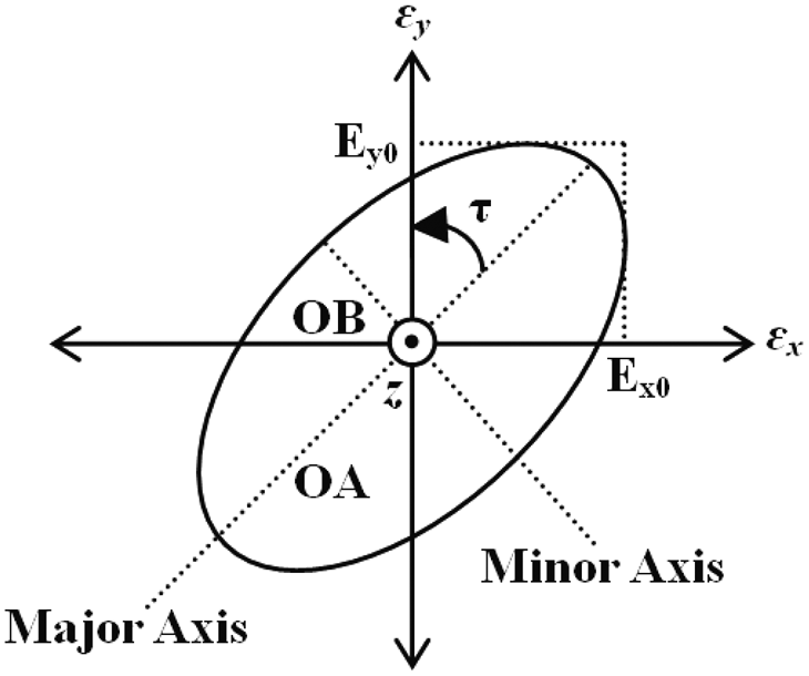
Fig. 2. Polarization ellipse showing parameters of polarization [Reference Balanis1].
A general planar microstrip patch antenna on its own does not radiate CP wave; subsequently, some modifications should be done to the patch antenna to be able to generate the circular polarization [Reference Row and Ai3–Reference Sudha, Vedavathy and Bhat10]. In the following sections of this review, a detailed discussion is presented about the various techniques adopted by researchers to generate circular polarization. Each categorical description includes the basic methodologies, progressive evolution of design trends, and comparative study of different antennas reported in the literature. CP microstrip antennas can be classified according to the number of feeding points required to produce CP waves. The most widely used feeding networks incorporated are dual or multiple feed and single feed.
Dual feeding network
As 90° phase shift between the orthogonal fields in the microstrip antenna is a mandatory pre-requisite for having circular polarization, dual feed is an obvious way to generate circular polarization in microstrip antenna. The two feed points are chosen spatially orthogonal [Reference James and Hall4] to each other as shown in Fig. 3. With the help of an external polarizer, the microstrip patch antenna is fed by signals which are equal in magnitude and in phase quadrature. The substrate has the dimensions of w = 45 mm, l = 55 mm, the feed lines have width wm = 3.5 mm, and lengths lm 1 = 18 mm, lm 2 = 16.5 mm. The gap g is taken to be 1 mm in dimension. Dual feed operation can be carried out using quadrature hybrid coupler, ring hybrid coupler, Wilkinson power divider, T-junction power splitter or two coaxial feeds with a physical phase shift of 90° [Reference Row and Ai3, Reference Li, Lai and Sun6]. Generally, dual-fed CP antennas have a comparatively wider operational bandwidth. But this comes at the cost of increased design complexity to achieve satisfactory CP performance.
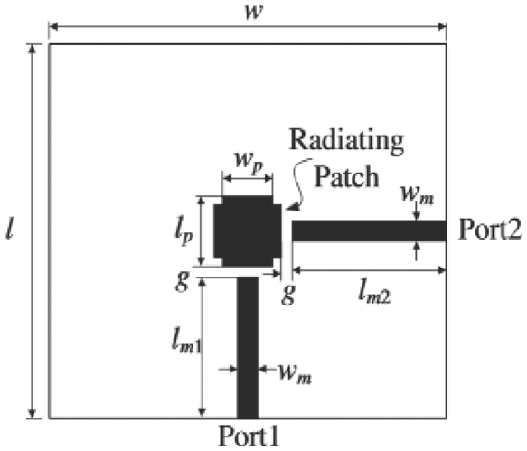
Fig. 3. Example of dual-fed CP patch [Reference James and Hall4].
Single feeding structures
Single fed microstrip antennas are structurally simple, easy to fabricate, low cost and compact in structure as shown in Fig. 4. It eliminates the use of a complex hybrid polarizer, which is very complicated to be put in physical use [Reference Haneishi, Nambara and Yoshida7]. Single fed CP microstrip antennas are considered to be one of the simplest antennas that can produce circular polarization [Reference Nasimuddin, Yong, Chen and Alphones8]. In order to achieve CP using only a single feed, two degenerate modes should be exited with equal amplitude and 90° phase difference. Since basic shapes microstrip antenna produces linear polarization there must be some changes in the design to produce circular polarization. Perturbation segments are used to split the field into two orthogonal modes with equal magnitude and 90° phase shift. Therefore the circular polarization requirements are met. The most prominent advantage of single fed CP antennas is simplicity in design. But on the contrary, single fed CP antennas have a narrow operational bandwidth and so there has to be some additional mechanism to increase the operational bandwidth while maintaining the structural simplicity. Acceptability of the design depends upon these mechanisms and optimized results.

Fig. 4. Example of single-fed CP patch Antenna [Reference Haneishi, Nambara and Yoshida7].
In general, CP antennas can be created in a wide number of ways. A method to generate CP waves is by introducing perturbation [Reference Row and Ai3, Reference Ravipati and Shafai9, Reference Sudha, Vedavathy and Bhat10] in the antenna. The small perturbation has to be coherent with the desired frequency to produce two orthogonally polarized components with the same amplitude and a 90° phase difference.
Single feeding techniques are mostly adopted in modern microstrip antenna designs as they are simple, easy to fabricate, low in cost and compact in structure.
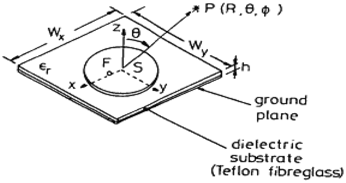
Several techniques [Reference Haneishi, Nambara and Yoshida7–Reference Chen, Wu and Wong14] were used to achieve circular polarization in single fed microstrip antenna. Some of these are discussed here. In [Reference Haneishi, Nambara and Yoshida7], a single-fed CP patch antenna has been shown which is fabricated on a Teflon fiberglass substrate of height “h” = 1.2 mm, “Wx” = 27 mm, “Wy” = 27 mm. The radius of the circular disc radiator is 10.5 mm. Till date, some review analysis has been performed on individual aspects of CP antennas, like circularly polarized dielectric resonator antennas [Reference Ullah, Ain and Ahmad15, Reference Dash and Khan16], fractal CP Antennas etc. But a comprehensive review of CP antennas as a whole, along with the vast domain of their applications is rare in the existing literature. This review article is an effort to fill up that void in the research document.
However, CP antennas can be classified into different types, based upon various aspects. This can be seen in the following set of flowcharts (Fig. 5).

Fig. 5. Flowcharts showing different classifications of CP antennas based on (a) number of feeds, (b) bandwidth achieved, and (c) antenna structure.
CP wide band antennas
Generally, as pre-mentioned, there are two major techniques to generate circular polarization, single feed [Reference Haneishi, Nambara and Yoshida7–Reference Sudha, Vedavathy and Bhat10] and dual or multiple feed [Reference Ludwig2, Reference Row and Ai3, Reference Li, Lai and Sun6]. Most of the single feed CP antennas, although structurally simple; suffer from significantly narrow CP (3-dB) AR bandwidth and impedance bandwidths [Reference Haneishi, Nambara and Yoshida7–Reference Ravipati and Shafai9,Reference Chen, Wu and Wong14]. The huge requirement of modern-day high data rate communication among interacting systems inherits the necessity of increased bandwidth to accommodate this bulk data transmission. Correspondingly, the single-fed antennas cannot be used in wide band applications [Reference Chen, Wu and Wong17,Reference Tamakuma and Iwasaki18]. However, the dual-feed CP antennas generate a wider AR bandwidth but come along with additional design complexity. The printed CP slot antenna is suitable to use for improving operating bandwidth without increasing the substrate thickness or antenna size. The slot antenna with wide-slot aperture can provide greater bandwidth and have better manufacturing tolerances as compared to a conventional microstrip patch antenna [Reference Nasimuddin and Qing19]. Several types of techniques are proposed to improve AR bandwidth of the CP antennas. One of them is the creation of antenna array configuration with wideband hybrid couplers and power dividers. This technique could considerably increase AR bandwidth up to 20% [Reference Huang20] or by using four-element antennas over to 163% [Reference Chan, Tan and Rambabu21] but these approaches may not be feasible in specific applications with constrained dimensional flexibility. Also, these approaches make the feeding network exceedingly complex for practical fabrication. However, an obvious choice yielding wide impedance and CP bandwidth with planar and compact structure is the slot antenna [Reference Yang, Kishk and Lee22–Reference Sze, Hsu, Chen and Chang24]. The most attractive feeding method of wideband CP slot antennas is microstrip line and coplanar waveguide (CPW). Several types of various-shaped wide-slot antennas for improving CP radiation have been reported. These include asymmetric aperture antenna using CPW feed with 68% [Reference Nasimuddin and Qing19], L-shaped slot antenna providing 46.5% AR bandwidth [Reference Yang, Kishk and Lee22], microstrip-fed circular slot antenna [Reference Tseng and Han23], and a CPW-fed square slot antenna with AR bandwidth 49% [Reference Sze, Hsu, Chen and Chang24].
In [Reference Sze, Hsu, Chen and Chang24], a CPW-fed broadband CP antenna is shown, which is fabricated on FR4 substrate of dimensions 60 × 60 × 0.8 mm3.The square slot side length is L = 40 mm. Within the slot there is a lightning-shaped feed-line of length s = 36 mm, which is connected to a vertical feed line, as shown in Fig. 6(a), having dimensions of wf = 4.2 mm, ws = 2.5 mm, ln = 10 mm. On two opposite corners of the slot, there are two L-shaped strips defined by the dimension d = 15 mm. The lightening-shaped feed line protruded from the CPW and the pair of inverted-L grounded strips both contribute to the generation of CP radiation. The vertical and horizontal tuning stubs have effectively widened the return loss bandwidth, as seen in Figs 6(b) and 6(c). The measured antenna gain in the broadside direction considered within the 3-dB AR band of 2075–3415 MHz are reported to be within 2.6–4.2 dBic, which are large enough for short-range wireless communication systems.

Fig. 6. A CPW-fed broadband CP antenna showing (a) proposed structure, (b) return loss bandwidth, (c) axial ratio bandwidth [Reference Sze, Hsu, Chen and Chang24].
32.2% AR bandwidth and 132% impedance bandwidth with more complex geometries have been presented in [Reference Pourahmadazar, Ghobadi, Nourinia, Felegari and Shirzad25]. A wideband microstrip line-feed CP slot antenna was proposed using the dual-feed with an integrated ultra wideband (UWB) phase shifter in multi-layer structure [Reference Narbudowicz, John, Sipal, Bao and Amman26]. CP bandwidth of the antenna is 54%. Recently, another microstrip-fed CP wide slot antenna with 90.2% and impedance and 40% AR bandwidths has been presented in [Reference Ellis, Zhao, Wu, Ding, Nie and Liu27].
For high-speed data transmission and/or multifunctional services, broadband CP antennas are often demanded. In recent years, a number of broadband CP antennas have been proposed [Reference Nakano, Nogami, Arai, Mimaki and Yamauchi28–Reference Fu, Kong, Fang and Wang42]. Broadband circular polarization may be achieved by traveling-wave antennas [Reference Nakano, Nogami, Arai, Mimaki and Yamauchi28–Reference Hung and Lin31], crossed dipoles [Reference Qu, Chan and Xue32–Reference He, He and Wong34], stacked patches [Reference Chung35–Reference Yang, Zhou, Yu and Li38], or broadband 90° hybrid feed networks [Reference Guo, Bian and Shi39–Reference Fu, Kong, Fang and Wang42]. Traveling-wave antennas usually need a broadband balun [Reference Li, DeJean, Laskar and Tentzeris29] or a transformer [Reference Zhang and Zhu30] for impedance matching. The traveling-wave aperture antenna proposed in [Reference Hung and Lin31] needs a cavity and the 3-dB AR bandwidth, which is about 21% for the antenna element. The crossed triangular bowtie dipole antenna developed in [Reference Qu, Chan and Xue32] also needs a feeding balun. The 3-dB AR bandwidths achieved by crossed-dipole antennas through a 90° phase delay line are 28.6% in [Reference Baik, Lee, Pyo, Han, Jeong and Kim33] and 27% in [Reference He, He and Wong34], respectively. The H-shaped stacked patch achieves an AR bandwidth of 19.4% [Reference Chung35] while the aperture-fed patch antenna has an AR bandwidth of 33.6% [Reference Oraizi and Pazoki36]. The cavity-backed aperture stacked patch antenna provides an AR bandwidth of 43.3% [Reference Yang and Zhou37] while the single-fed stacked patch antenna in [Reference Yang, Zhou, Yu and Li38] features an AR bandwidth of about 20.7%. The CP antennas using a broadband 90° hybrid feed network usually exhibit a broad AR bandwidth, e.g., 38% in [Reference Guo, Bian and Shi39], 33% in [Reference Mak and Luk40], 51.8% in [Reference Zhang, Liu, Zhao and Fu41], and 16% in [Reference Fu, Kong, Fang and Wang42]. Stacked patches and/or 90° hybrid feed networks may complicate the antenna design and fabrication.
In recent years, there has been growing interest in UWB antenna technology for short-range, high data rate wireless communication. Hence, research in the design of UWB equipments and antennas has received progressive attention. These antennas usually attempt to match the Federal Communications Commission (FCC) specified bandwidth covering from 3.1 to 10.6 GHz in its report in 2002 [Reference Ahmed and Sebak43, Reference Mextorf, Martens, Daschner and Knochel44], which is known as the UWB spectrum. In most cases, the monopole UWB antenna is widely used due to their lightweight, wide impedance bandwidth, good radiation characteristic, easy of fabrication and low cost. However, most of the UWB monopole antennas designs are based on linear polarization [Reference Zhao, Yang, Zhu and Chen45–Reference Tang, Shi and Ziolkowski48]. Indeed, the UWB technology is limited by distance due to very low transmitting power. To obtain distance gain, and also other pre-mentioned benefits the use of circular polarization (CP) in UWB technology is advantageous. The UWB CP antennas are used widely in military applications such as electronic countermeasure system, UWB radar, and medical applications [Reference Jou, Wu and Wang49].To obtain UWB CP, some design techniques have been studied [Reference Jou, Wu and Wang49–Reference Pancera51]. In [Reference Jou, Wu and Wang49], the authors use an inverted–L shape in the ground plane to generate a resonant mode for broadband impedance bandwidth and excite two orthogonal electric field vectors with equal amplitude and 90° phase differences. In addition, cutting a bevel in the radiator patch increases the impedance bandwidth. This article consists of another design which is an I-shaped stub in the ground plane and a slot in rectangular radiator patch. In the second design, the impedance bandwidth increased compared to the first design frequency, from 2.17 to 8.47 GHz, hence, could not cover the whole of UWB frequency. In [Reference Banerjee, Karmakar, Chakraborty and Saha50], a CPW-fed monopole antenna with wideband circular polarization is reported. The monopole, an upper parasitic strip and a modified parasitic Hilbert strip are coupled together by proximity coupling yielding a significantly wide impedance bandwidth. The antenna has an impedance bandwidth ranging from 2.04 to 7.95 GHz (118.2%) and an AR bandwidth ranging from 3.6 to 6.84 GHz (62%), thus covering the WLAN 5.2/5.8 GHz, the WiMAX 3.5/5.5 GHz and also partially covering the C-band (4–8 GHz). The antenna shows good radiation characteristics and obtains a reasonable gain over the entire operating frequency band. The antenna gain varies between 2.7 and 4.32 dB within the operating frequency band of the antenna. The maximum efficiency of the antenna is obtained to be 95.4% at 5.5 GHz.
A comparative study on the different approaches exploited to generate a wide impedance bandwidth with circular polarization is presented (Table 1).
Table 1. Comparative study of different circularly polarized antennas having wide impedance and axial ratio bandwidths

We can highlight the following analytical conclusion based upon the literature and the comparison:
(i) Generally, the operational bandwidth of CP antennas [Reference Chen, Wu and Wong14] with conventional designs is relatively narrow.
(ii) Single-fed structures [Reference Chen, Wu and Wong14, Reference Nakano, Nogami, Arai, Mimaki and Yamauchi28] usually have narrow AR bandwidths. However, exceptions are also there as reported in [Reference Nasimuddin and Qing19, Reference Yang, Kishk and Lee22, Reference Banerjee, Karmakar, Chakraborty and Saha50, Reference Pancera51].
(iii) By using complicated feeding structures like hybrid feeding [Reference Guo, Bian and Shi39], power divider networks [Reference Mak and Luk40], impedance bandwidth, as well as AR bandwidth can, however, increase at the cost of higher design complexity.
(iv) Operational bandwidth can also be increased by increasing the overall dimensions, possibly by introducing, stacked structures [Reference Oraizi and Pazoki36], air gaps [Reference Fu, Kong, Fang and Wang42], using cavity backing [Reference Nasimuddin and Qing19], and using reflectors [Reference Nakano, Nogami, Arai, Mimaki and Yamauchi28] etc, which might increase the return loss and the AR bandwidth or the gain in some cases, but make the antenna unsuitable for multiple system integration.
(v) Some novelty in the structure has also been observed in [Reference Sze, Hsu, Chen and Chang24,Reference Nakano, Nogami, Arai, Mimaki and Yamauchi28] which reported reasonable performance characteristics.
(vi) The concept of partial impedance steps is introduced in [Reference Banerjee, Karmakar, Chakraborty and Saha50], which improves matching greatly, resulting in a wide impedance as well as AR bandwidth, minimizing metallization. The radiation efficiency also increases significantly.
CP dielectric resonator antennas (CP DRA)
DRAs form a domain of very promising radiating elements, particularly for high-frequency applications. Although, in the primitive state of applications, the dielectric resonators (DRs) were used as filters and oscillators i.e. energy storage elements, Richtmyer in 1939 [Reference Richtmyer52] first published a comprehensive article showing that these resonators can also be used as efficient radiators. The first theoretical and experimental analysis of a cylindrical DRA was carried on by Long et al. in 1983 [Reference Long, McAllister and Liang53]. Since then DRA technology has been growing tremendously and has become a focal area for modern wireless communication engineers. A DRA basically consists of a block of dielectric material (especially having high dielectric constant), glued on the top of a patch or a planar monopole over a substrate (of a relatively lower dielectric constant). The antenna may or may not have a ground plane.
DRAs usually use a block of dielectric ceramic as the basic radiating element. So in a way, they reduce metallization, which in turn reduces conduction loss as compared to conventional microstrip antennas. Also the power loss due to surface currents is minimized. This entitles DRAs to enjoy higher gain, better radiation efficiency and generally higher bandwidth than their conventional microstrip monopole counterpart. Also, depending upon the fabrication of the DR geometry and proper design of the feeding network, different modes can be excited within the DR, and they can be efficiently controlled as well providing design flexibility and result optimization.
In [Reference Agarwal, Gupta, Parihar and Kondekar54], a novel high gain and broadband hybrid DRA is designed and experimentally verified. To obtain the wide impedance bandwidth, the proposed antenna geometry combines the DRA and an underlying slot with a narrow rectangular notch, which effectively broadens the impedance bandwidth by merging the resonances of the slot and DRA. An inverted T-shaped feed line is used to excite both antennas, simultaneously. It supports articulation of different resonant modes of the both, DRA and slot antenna. The proposed antenna offers an impedance bandwidth of 120% from 1.67 to 6.7 GHz. The antenna gain is enhanced by a reflector placed below the antenna at an optimum distance. On optimizing the height and dimension of this reflector the antenna gain is improved from 2.2 to 8.7 dBi at 1.7 GHz.
Mongia et al. published a comprehensive review of the modes and the radiation properties of several DRs [Reference Mongia and Ittipiboon55], whereby accurate close form expressions for the resonator frequencies, radiation quality factors and fields inside a DR were also described. Since inception, the volume of research that has continued till recently about DRAs has mostly been reported to have linearly polarized radiation pattern [Reference Denidni, Rao and Sebak56–Reference Guha and Antar88]. So setting aside the inherent benefits offered by a DRA like enhanced gain and increased radiation efficiency due to low metallization, the operation often gets limited as a result of the linear polarization. This potential difficulty was considered with due concern and as a result of ongoing research saw the introduction of CP DRA. The ability of DRAs to support multiple radiating modes simultaneously is well exploited in the design of CP DRAs.
Design of CP DRAs commenced with [Reference Haneishi and Takazawa89] that proposed a rectangular DR, with two opposite corners truncated similarly as with a rectangular patch microstrip antenna to produce CP. Mongia et al. [Reference Mongia, Ittipiboon, Cuhaci and Roscoe90] produced CP by exciting two orthogonal HE11δ modes of a cylindrical ring DRA using a 3 dB quadrature coupler. In [Reference Esselle91], a slot coupled rectangular DRA is used where the DRA position is adjusted to 45° with respect to the slot to produce CP over a bandwidth of 3.4%, and beamwidth of 110°. A design with dual conformal strip feed [Reference Leung, Wong, Luk and Yung92] can also produce CP over a wider bandwidth of 20%. In some designs, backing cavities are used [Reference Leung and Mok93] to block back lobe radiation, thereby enhancing the gain of the antenna. A novel structured DRA in the form of a stair-shaped DR fed by a slot is also reported [Reference Chair, Kishk, Yang, Lee and Luk94], generating CP over a bandwidth of 10.6%. A cylindrical DRA with longitudinal slots of limited depth has been demonstrated [Reference Guha, Antar and Chu95] to produce CP over just 4% AR bandwidth.
It has been observed that majority of the CP DRAs in literature use either rectangular or cylindrical shaped DRs, though other DR shapes are also used to some extent. The shape of the DR and also the architecture of the feeding network can be optimized to generate requisite modes and thereby radiate circular polarization. Thus, these parameters do offer a great deal of design flexibility for arriving at the desired results. In a cylindrical DRA, one of the major controlling factors for obtaining circular polarization are the aspect ratio, which is the ratio of the diameter to the height of the cylindrical DR [Reference Mongia96]. For sectored DRAs [Reference Tam and Murch97], the sector angle is also a controlling parameter for circular polarization.
In [Reference Hady, Kishk and Kajfez98], a two-port fed cylindrical DRA has been proposed for CP operations. It consists of an annular cylindrical DR placed in an open space environment above a circular TMM6 thermoset microwave substrate of dielectric constant 6.15 and thickness of 1.524 mm. The resonator has an outer radius of RDRo = 8.82 mm, inner radius, RDRi = 2 mm, the height of 7.9 mm, and a dielectric constant of 38. The L-shaped lines are placed at a distance of d = 5.8 mm from the center of the resonator. From the latter edges, curved lines of width w1 = 0.8 mm are used. At the 90° phase difference junction, the two parallel 80Ω lines will meet resulting in 40 Ω impedance. Therefore, a quarter-wavelength transformer of width w 2 = 2.7 mm can be utilized to obtain 50 Ω impedance at the edge where an SMA connector is connected to form port 1. Figure 7(b) shows the rotation of electric field vectors inside the DR at 3.15 GHz by exciting the port 1 and terminating the port 2 with a matched load impedance, as shown in Fig. 7(a). The corresponding AR bandwidths of the antenna in two orthogonal planes are shown in Fig. 7(c). It can be observed that the electric field lines are not deformed significantly within the resonator due to the existence of the conducting probe inserted inside the resonator, shown in Fig. 7(a). This ensures the polarization purity of the antenna.

Fig. 7. (a) A circularly polarized DRA showing (a) schematic structure, (b) electric field rotation, and (c) axial ratio bandwidth [Reference Hady, Kishk and Kajfez98].
A rigorous survey on the various techniques used for designing CP DRAs informs us that circular polarization can be obtained from a DRA using the following methods:
(i) Single-point fed CP DRA [Reference Denidni, Rao and Sebak56–Reference Leung and So72].
(ii) Multi-point fed CP DRA [Reference Leung, Wong, Luk and Yung92, Reference Hady, Kishk and Kajfez98–Reference Chan, Zhong and Liu100].
(iii) CP DRA using sequential rotation technique [Reference Petosa, Ittipiboon and Cuhaci101–Reference Yang, Chair and Kishk103].
(iv) Slotted or sectored CP DRAs [Reference Fan and Antar85, Reference Tam and Murch97].
However, a multi-point fed CP DRAs and sequential rotation method results in designing a feeding network which is relatively more complex and difficult to control optimally, but, if properly exploited by proper mathematical models and sound simulation techniques, may yield impressive results, as already discussed.
Unlike single-point fed CP DRAs, which are simple to fabricate, but typically of narrow bandwidth, multi-point fed DRAs, although structurally complex, may yield wider AR bandwidths. The authors in [Reference Li, Hao and Sheng99] reported a rectangular-shaped DRA, excited with vertical strips, in combination with a phase quadrature network. As a result of this excitation, multiple CP modes (TE 111 and TE 113) were generated simultaneously in the rectangular DR for an enhanced AR bandwidth. Although, the theoretical resonant frequencies of the fundamental mode TE 111 and the higher-order mode TE 113 were found to be different, however, the resonance of these two modes occurred close to each other. In this design, both the modes were generated in the x- and y-directions by placing equal size vertical strips on the two side walls of the rectangular DR. The reported impedance bandwidth of the antenna was 32.8%. The measured AR bandwidth of the antenna was measured to be lying within the entire impedance bandwidth.
Another interesting structure for broadband CP DRA was illustrated in [Reference Chan, Zhong and Liu100]. In this paper, a two-point feed is used in combination with a switched line coupler for exciting a rectangular DR for radiating CP fields. In the structure, a square-shaped DR was placed in the center of a grounded substrate. The resonator was excited by a 3 dB Wilkinson power divider and a wideband 90° phase shifter. The switched line coupler circuit was printed on the front side of the substrate, while the DR was placed on the ground plane. The Wilkinson power divider circuit serves the purpose of equal power division between the different feeding arms and also impedance transformation between the input and the output ports. A couple of quarter wave transformers were used to split the signal from the input port into two different paths and then transmit it, so as to generate a 90° phase difference at the output ports. This structure generates an AP bandwidth of 48% and also stable main beam radiation properties in the broadside of the antenna.
The notable drawback of the two-point fed network, as already has been mentioned, is an increased level of metallization, due to the requirement of additional circuit area for designing the power divider network. Also, the overall antenna architecture is quite complicated. An alternative technique is the sequential rotation mechanism, whether either the feeding network or the antenna elements are rotated sequentially. It is worthy to note here that in this technique, the feeding is necessarily single-point, thus maintaining structural simplicity.
The feeding network for sequential rotation is designed in such a manner that the antenna elements are energized in a progressive 90° phase shift at each excitation point. Several research articles [Reference Petosa, Ittipiboon and Cuhaci101–Reference Fakhte, Oraizi and Karimian104] showing the use of sequential rotation feeding technique to generate circular polarization in DRA do exist in literature.
In [Reference Laisne, Gillard and Piton102], a CP DRA with a metallic strip is reported. The antenna uses a sequential rotation feeding to generate circular polarization. The bandwidth below –10 dB is smaller than the corresponding single element counterpart, which is attributed to the small bandwidth of the feeding network. The measured and simulated AR along the z-axis for the array confirms the enhancement of AR brought about by the sequential rotation. In particular, the array exhibits an AR below 1.5 dB over the whole –10 dB matched band, which represents a bandwidth over 18%. Measured losses at 14.6 GHz reach 0.56 dB for the array and are mainly due to the feeding network. The measured and simulated left-handed CP (LHCP) far fields and right-handed CP (RHCP) far fields.
In [Reference Yang, Chair and Kishk103], the authors reported three different types of sequentially rotated fed DRA. In the most commonly used configuration, the feeder shows an input port which is a 50 Ω microstrip line. A few quarter-wave impedance transformers are used to divide the input power into four output ports. The output points are arranged in such a way that each point is located at a distance such that mutual coupling between the resonating elements does not affect the radiation properties. The corresponding output points are excited with a 90° phase shift signal in an anti-clockwise sequence. Furthermore, the corners of the microstrip line are chamfered for a smooth transformation of power at the junction discontinuities of the feeding network. The output of the parallel-feed network was coupled to the antenna using probe and slot configuration which yielded AR bandwidths of 26 and 23%, respectively.
Although in this work, the input port is considered to be a 50 Ω microstrip line, but this can only be considered for thin substrates. For thick substrates, 50 Ω line impedances is not recommended as it will increase the coupling in the center of the circuit, which will lead to radiation losses in the feeding network.
It is also indicated from various experimental results that further improvement in the CP DRA can be achieved by using inhomogeneous DRs with special geometries, or by modification of the dielectric characteristics of the common DR shapes in the azimuth direction.
A stacked DRA [Reference Fakhte, Oraizi and Karimian104] for CP characteristics is shown in Fig. 8(a). The rotation of the electric field vectors at two frequencies of 9.5 and 10.15 GHz are shown in Figs 8(b) and 8(c), respectively. It is observed from this study that the excited mode is clearly TEy 111at 9.5 GHz, since the E-field is mostly oriented along the x-axis and that TEx 111 mode excited at 10.15 GHz, since the E-field is mostly oriented along the y-axis. The corresponding AR bandwidth is shown in Fig. 8(d).

Fig. 8. A CP DRA showing (a) the fabricated prototype, (b) electric field distribution at 9.5 GHz, (c) electric field distribution at 10.15 GHz, and (d) axial ratio bandwidth [Reference Fakhte, Oraizi and Karimian104].
A comparative study for different reported papers on CP DRAs presented. The analysis highlights different techniques used, results obtained and further scope of research (Table 2).
Table 2. Comparative study of different circularly polarized dielectric resonator antennas (CP DRAs)

Fractal based CP antennas
According to Mandelbrot [Reference Mandelbrot105], fractals are defined as “a rough or fragmented geometric shape that can be split into parts, each of which is (at least approximately) a reduced-size copy of the whole”. The major characteristic feature of the fractal geometry is perhaps its “self-similarity” in multiple orders of its iteration. As the order of iteration increases, the structure becomes complex, no doubt, but at the same time, the total length of the fractal progressively increases, keeping the overall peripheral dimensions unchanged (Fig. 9).

Fig. 9. Different fractal structures like (a) Koch Snow flake (b) Sierpinski Carpet, and (c) Hilbert Fractal [Reference Mandelbrot105].
A fractal antenna is an antenna that employs the fractal, self-similar design to maximize its effective length or increase the perimeter (on inner sections or the outer periphery) of a material (patch or a monopole) that can receive or transmit electromagnetic radiation, maintaining a given total surface area or volume.
Such fractal antennas are also referred to as multilevel and space -illing curves, but the key aspect lies in their repetition of a pattern over two or more scale orders, or “iterations”. For this reason, fractal antennas are usually very compact in nature. They may exhibit multiband or wideband radiation and have useful applications in telephonic communication and other recent aspects of wireless communications. A fractal antenna's response differs remarkably from traditional antenna designs, in that it is capable of operating with good-to-excellent performance at many different frequencies simultaneously [Reference Werner and Ganguly106–Reference Pakkathillam, Kanagasabai, Varadhan and Sakthivel109]. Normally standard antennas have to be physically sized for the resonant frequency meant for their use and thus the standard antennas only work satisfactorily at that frequency.
A novel design, based upon a modified Koch fractal geometry has been designed for achieving circular polarization with a square radiator by creating a pair of asymmetric Koch fractal geometries on the x- and y-planes of a single probe feed [Reference Farswan, Gautam, Kanaujia and Rambabu110]. A defected ground structure (DGS) is designed based upon fractal geometry for improving antenna characteristics like operational bandwidth, cross-polarization levels and gain in [Reference Wei, Li, Wang, Xu and Xing111]. Planar CP fractal antennas have been extensively studied and reported in the literature for WLAN applications [Reference Pakkathillam and Kanagasabai112] owing to their compact dimensions.
In [Reference Pakkathillam and Kanagasabai112], iteration factor (IF) is also varied to study the performance of the antenna. The novel motive of this work is bringing out the link between the IF and the AR bandwidth for the design of a broadband antenna, proving that IF is also an influential parameter in fractal CP antenna design. The method used in this paper is a hybridization of fractal structure and diagonal slots. A broadband response is achieved compared to conventional diagonal slot design (Fig. 10).

Fig. 10. The (a) structure of a CP fractal Antenna and its (b) VSWR, and (c) axial ratio Bandwidth [Reference Pakkathillam and Kanagasabai112].
Further, for GPS applications, a circular patch cross-over module has been reported in [Reference Jayakrighnan and Sreedevi113]. A CP fractal antenna for GPS system using a modified and optimized Minkowski fractal structure has been demonstrated in [Reference Joy, Natarajamani and Vaitheeswaran114].
A popular method to obtain circular polarization using fractal geometry is employing DGS [Reference Biswas, Guha and Kumar115–Reference Kim and Lee118], which are tactically etched portions from the ground plane, which can perturb the surface current distribution on the ground plane. By embedding the DGS, the field of one mode of the excited field vector can be made to lead by 45° while that of the other can lag by 45°, resulting in a 90° phase difference necessary for circular polarization. Thus as DGS increases the AR bandwidth for circular polarization [Reference Kim and Lee118].
In [Reference Prajapati, Krishnamurthy, Patnaik and Kartikeyan119], the methodology proposed is to replace the straight sides of the square patch by different fractal curves. Because of this slight difference in electrical length in two mutually perpendicular directions of the patch, two spatially orthogonal modes are excited. By effective dimensional tuning of the fractal curves, compact CP fractal microstrip antennas can be realized. In addition to the generation of CP, it is always possible to attain structural miniaturization.
In [Reference Reddy and Sarma120], a single probe-fed singly layer antenna is proposed. The antenna design is based upon Minkowski and Koch fractal geometries. The antenna shows tri-band radiation characteristics with impedance bandwidths 12.7, 2.52, and 7.5% respectively, while exhibiting AR bandwidths of 1.53, 0.81, and 1.62%, respectively. The proposed antenna is suitable for WLAN and WiMAX applications.
In recent works, the concept of fractal geometries in the microstrip antenna design has been incorporated for multiband, wideband, and size reduction [Reference Reddy and Sarma121, Reference Baliarda, Romeu and Cardama122]. Tri-band CP radiation was achieved by using asymmetrical Koch fractal curved boundaries and embedding rectangular slot in a square patch structure [Reference Reddy and Sarma121]. The behavior of the Koch fractal-based monopole is numerically and experimentally analyzed to show that the quality factor of the antenna approach to the fundamental limit for geometrically small antennas, as the number of iterations is increased on the small fractal Koch monopole [Reference Baliarda, Romeu and Cardama122].
In [Reference Rao and Sarma123] a unique method is proposed to obtain decent circular polarization using a fractal curve as the boundary of the antenna. This is achieved by choosing a proper fractal shape and dimension in each side of a square patch while keeping the dimension constant for the opposite sides. The length of the fractal curve can be effectively tuned by altering the fractal dimension. Circular polarization, as previously mentioned, can be obtained when two orthogonal modes with equal amplitudes, which are excited within the patch. This is possible by choosing different electrical lengths in two directions of the patch. When a Koch curve with a different indentation angle is used as the boundary for the square patch, its electrical length varies since the length of the Koch curve is a function of indentation angle. The length of the nth iterated Koch curve can be expressed as:

where, n = iteration number, L = initial length of the curve, Ln = length of the curve after nth iteration, θ = indentation angle.
The fractal dimension of the Koch curve in terms of the indentation angle is given as

where, s = 2(1 + cosθ) = scaling factor, D = fractal dimension, N = number of segments.
So, in this paper, the concept of varying the fractal dimensions of the boundary is employed to achieve different electrical lengths in two directions of the patch, which in turn excites two orthogonal modes necessary for circular polarization.
The Jerusalem cross (JC) is another notable fractal model used in a number of researches for increasing antenna gain and bandwidth enhancement [Reference Arezoomand, Zarrabi, Heydari and Gandji124, Reference Wang, Liu, Hu, Kong, Cheng and Chen125]. In addition, the slot antenna has been studied to achieve circular polarization with a change in slot feeds and parasitic elements in some researches [Reference Zarrabi, Mansouri, Ahmadian, Rahimi and Kuhestani126–Reference Pouyanfar131]. Slot antennas with various techniques for obtaining circular polarization are implemented, such as square-ring slot antenna fed with an L-shaped coupling strip [Reference Row and Lin127], dual-square ring-shaped slot [Reference Qing and Chen128], and two-slot rings [Reference Wang and Yang129]. Coplanar waveguide (CPW)-fed slot antennas such as two asymmetrical C-shaped strips [Reference Wei, Liu, Bor, Hung and Chen130] and corner-truncated ground [Reference Pouyanfar131] are also noticed for the feasibility of achieving circular polarization.
In [Reference Heydari, Jahangiri, Arezoomand and Zarrabi132] a fractal JC slot antenna is designed for circular polarization. For this aim, a special shape of the slot, a broken cross shape is used to alter the antenna's surface current distribution to achieve circular polarization. In addition, a T-shaped feed line is used to increase the effective length of the antenna for miniaturization and saving symmetrical formation of the antenna for obtaining circular polarization, and a triangular slot in feed line is used for improving the antenna's impedance matching. In addition, by varying the length of the feed line, a fair control of the coupling to the ground plane is achieved and therefore the best length for matching has been attained. At last, the JC slot is implemented on the ground plane.
In [Reference Oraizi and Hedayati133] a multiband CP antenna is introduced using the novel square and Giuseppe Peano fractals. It is designed for operation in, Global positioning system L1 (GPS 1.575 GHz); Hiper-Lan2 (High Performance Radio Local Area Network Type2) in the band 2.12–2.32 GHz; IEEE802.11b/g in the band from 2.4 to 2.484 GHz, which is one of the WLAN bands and IMT advanced system or fourth-generation (4G) mobile communication system in the band 4.6–5.2 GHz. The miniaturization and multi-banding [Reference Jahromi and Komjani134] properties of the square fractal microstrip patch antenna is also investigated and presented (Table 3).
Table 3. Comparative study of different circularly polarized fractal antennas

Metamaterial based CP antennas
Metamaterials are structural units typically designed with novel or artificial components to generate electromagnetic properties that are unusual or difficult to be obtained in nature. This concept is incorporated in designing antennas [Reference Blanco, Rajo-Iglesias, Maci and Llombart135–Reference Ko, Park and Lee143] during the last few decades. Metamaterial antennas are a class of antennas involving metamaterials to enhance their capability or to achieve novel functions. They can be classified as leaky-wave antennas [Reference Blanco, Rajo-Iglesias, Maci and Llombart135] and resonator type antennas [Reference Xu, Wang, Liang, Qi and Gao136]. Metamaterial-based antennas may also be based upon meta-resonators [Reference Xu, Wang, Liang, Qi and Gao136] and/or metamaterial loadings [Reference Martin, Martinez, Turpin, Werner, Lier and Bray137]. These antennas have distinguished benefits like small physical dimensions, low cost, wide bandwidth, and good radiation efficiency.
It is pre-postulated that the quality factor and the radiation loss of the antennas are inversely related to the antenna size [Reference Sarrazin, Pflaum and Delaveaud138]. Metamaterial-based small antennas are proposed [Reference Ziolkowski and Erentok139] for providing means to manipulate the near field boundary conditions which could contribute to antenna miniaturization, maintaining good radiation performance. Metamaterial-based antennas have enlightened researchers to overcome the restrictive efficiency-bandwidth limitation for small antennas [Reference Ziolkowski and Jin140].
In [Reference Park and Lee141], a coaxial probe-fed cylindrical DRA is proposed that obtains an impedance bandwidth of 0.9% and an AR bandwidth of 0.4%. The antenna uses the zero-order resonator (ZOR) mode of epsilon negative (ENG)-based transmission line to obtain the omnidirectional radiation pattern and the vertical polarization. Also, the horizontal polarization is achieved by the curved branches. The gain obtained is low, about –0.4 dBic.
Metamaterial-based antennas, nowadays, are extensively used for the design of CP antennas. Various metamaterial-based CP antennas are reported in [Reference Blanco, Rajo-Iglesias, Maci and Llombart135–Reference Ko, Park and Lee143], some of which use complimentary split-ring resonators (CSRR) [Reference Zhou, Wang, Wang, Zong and Ma142], 2 × 2 mushrooms [Reference Ko, Park and Lee143], fractal resonators [Reference Cai, Wang, Zhang and Shi144], ENG-based transmission line-based annular rings [Reference Han, Yang, Long, Zhou and Yan145], sector-shaped circular array [Reference Chu, Ye and Li146]. In these reported antennas, it is observed that they suffer from narrow impedance bandwidth, narrow AR bandwidth, poor gain, comparatively higher design complexity, bulky size etc.
In [Reference Cai, Wang, Zhang and Shi144], the concept of Wunderlich-shaped fractal complementary split ring resonator (WCSRR) is introduced. Figure 11(b) shows the electric field distribution at 3.5 GHz in time-domain. A clockwise rotated electric field moving along the patch edge is observed, indicating the LHCP nature. Progressive research indicates that RHCP antenna can be designed by mirroring the WCSRR structure to the right part of the patch. In addition, the discrepancy of the electric field on WCSRR at different stages also justifies that the slot is essential in exciting the CP wave. The AR bandwidth is significantly improved for the antennas with Meandered line-loaded complementary split ring resonator (MCSRR) and WCSRR loading.

Fig. 11. The (a) structure of a metamaterial-based CP Antenna and its (b) electric field distribution at 3.15 GHz, (c) S11 bandwidth, and (d) axial ratio bandwidth [Reference Cai, Wang, Zhang and Shi144].
Metamaterial-based antennas are suitable radiators for the design of miniaturized low profile antennas. Metamaterials based on composite right/left-handed (CRLH) structures which offer negative or ZOR modes, which can be used for the design of miniaturized antennas [Reference Caloz and Itoh147, Reference Sharma and Chaudhary148].
In [Reference Ameen and Chaudhary149], a somewhat better solution with improved impedance bandwidth is presented. The proposed antenna is also relatively compact, low profile, and ENG-based transmission line-based CP metamaterial antenna. The measured impedance bandwidth of this antenna is 10.86%. Although the authors claim that this antenna performs better in comparison to the previously mentioned structures, the AR bandwidth obtained in this structure is only 2.54%.
In [Reference Yu, Yang and Elsherbeni150], a dual-band CP antenna, based on the principle of CRLH transmission line has been reported. In this structure, two separate power divider networks provide 90° phase shift between the two input ports. The antenna has dual bands at 1.768–1.776 GHz and 3.868–4.007 GHz i.e. 0.5 and 3.6% impedance bandwidths, respectively. The AR bandwidths range from 1.772 to 1.779 GHz and 3.953–3.972 GHz i.e. 0.39 and 0.48% AR bandwidths, respectively. Despite being the fact that the antenna has significantly narrow operational bandwidths, for both the bands, it can generate about 70% beam width for 3 dB level and has a decent peak gain of about 2.5 dB for both the bands.
Presently, vast attention is paid to research and development of chiral metamaterials due to their attractive electromagnetic properties [Reference Smith, Pendry and Wiltshire151]. In this type of metamaterials, the degeneracy of the two CP waves is broken i.e. refractive index for the RHCP and LHCP waves are different [Reference Jackson152]. Thus the RHCP and LHCP waves would have different transmission coefficients at the resonances. In [Reference Cheng, Nie, Cheng, Wang and Gong153], the chiral metamaterial concept is used to achieve RHCP and LHCP radiation at 6.4 and 8.1 GHz, respectively. The measured co-polarization and cross-polarization discrimination exceed 40 dB at the resonant frequencies, which is quite appreciable. The proposed structure based on bi-layer, twisted split ring resonator (SRR) approach can be made to exhibit dual-band or multiband operation by combining different sized twisted SRR structures. In addition, the proposed structure can also be operated at other specific high-frequency bands such as Terra-Hertz frequency range or even optical frequency range by downscaling geometrical dimensions.
Thus the review can summarily comment that when integrated with monopole or microstrip patch antennas, such metamaterial structures can improve different performance aspects such as provide gain enhancement [Reference Prakash, Abegaonkar, Basu and Koul154, Reference Jiang, Brocker, Sieber and Werner155], side lobe and back lobe reduction [Reference Wu, Scarborough, Werner, Lier and Wang156], antenna dimension miniaturization [Reference Jiang, Brocker, Sieber and Werner155, Reference Liu, Chen and Qing157], improve radiation efficiency [Reference Yang, Demir, Elsherbeni, Elsherbeni and Eldek158], support dual-mode operation [Reference Cao, Zhang, Liu, Yu, Guo and Pan159], and/or enable impedance bandwidth broadening [Reference Liu, Chen and Qing157].
A comparison table is provided which highlights some of the existing metamaterial-based CP antennas in the literature, with the motive to contribute to the vastly developing advanced domain of CP antennas (Table 4).
Table 4. Comparative study of different metamaterial-based circularly polarized antennas

Multiband CP antennas having novel structures and band-specific applications
Due to the enhanced system requirements of modern wireless communication applications, multiband CP antennas with structural compactness and broad bandwidth draw significant attention [Reference Ding, Gao, Liu, Yu and Qu160]. Also to cater to different specific bandwidth ranges, multiband antenna technologies with CP radiation pattern are in prominence [Reference Pouyanfar131, Reference Ding, Gao, Liu, Yu and Qu160–Reference Xu, Li, Liu, Zhou, Xing and Wei196]. In [Reference Li, Zhai HQ and Liang161], an antenna with a “T” shaped slit and an annular patch exhibits AR bandwidths of 4.02, 4.51, 1, and 12.74% at different operating bands. It is observed that though multiband, the AR bandwidths at the different operating bands are quite narrow. To overcome this, many broadband antennas with multiband CP characteristic feature are proposed [Reference Rui, Li and Wei162, Reference Guo, He, Zhang and Song163]. In [Reference Rui, Li and Wei162], dual-band, dual-sense CP square slot antenna presented. For enhancing the CP operational bandwidth, an artificial magnetic conductor (AMC) or metasurface is successfully applied in a number of designs [Reference Tran and Park164–Reference Huang, Pan, Ma and Luo166]. AMC can reduce the antenna physical dimensions and significantly enhances the CP operational bandwidth. However, this design approach makes the antenna structure complicated and hence unsuitable to be applied to integrated devices. Using parasitic patches in conjunction to the radiating patch is an effective solution to this problem [Reference Xiong, Li, Zhang and Zhang167]. In [Reference Xiong, Li, Zhang and Zhang167], an enhanced dual CP broadband antenna using C-shaped parasitic patch is reported. The overall length of the patch is about half wavelength corresponding to the resonant frequency of the lower band at 4.9 GHz.
In [Reference Paracha, Abdul Rahim, Soh, Kamarudin, Tan, Lo and Islam168], a low profile dual-band antenna for indoor/outdoor wearable applications is proposed. This antenna achieves about 63.86% size reduction related to a convention CP slotted patch antenna [Reference Ghaffarian, Moradi and Mousavi169], and about 15% as compared to other electromagnetically coupled CP antenna designs [Reference Torres-Garcia, Marante, Tazon, Vassal'lo, Teniente and Beruete170, Reference Torres, Marante, Tazón and Vassal'lo171]. This antenna [Reference Paracha, Abdul Rahim, Soh, Kamarudin, Tan, Lo and Islam168] uses a CSRR for size reduction and also to enable CP properties in the lower band. Further, to improve the gain and the front-to-back ratio (FBR) of the antenna, a compact and multi-band AMC unit cell is used. As a result, a gain improvement of upto 3.47 dBi and an increase in the FBR upto 21.88 dB in the lower band and upto 22 dB in the upper band was obtained, which is quite appreciable.
In [Reference Mohamed and Sultan172], a quad-band printed antenna is proposed for GPS (1.575 GHz), LTE (2.7 GHz), WiMAX (3.5 GHz), and WLAN (5.8 GHz) applications. The antenna uses a combination of four meandered lines which makes the AR bandwidth easily tunable. The authors have also demonstrated that the proposed antenna is suitable for Internet of Things (IoT) applications.
In [Reference Hsu, Shih and Wang173], a wideband monopole antenna has been proposed for applications of multiple system integration. The antenna achieves dual-band CP radiation with a triple sense topology. Although the AR bandwidths obtained are very narrow, yet the authors claim that the antenna can be used for GPS and SDAR bands, where LHCP and RHCP radiation are obtained, respectively.
In [Reference Tan and Wang174], a dual-band CP planar monopole antenna has been reported for WLAN/WiFi applications. The monopole radiator consists of a C-shaped strip and an L-shaped strip which are found to be responsible for the upper and the lower CP bands, respectively. The antenna structure is relatively simple.
In [Reference Chen and Yung175], a novel, dual-band CP CPW fed slot antenna is reported, which achieves a small frequency ratio and wide CP bandwidth simultaneously. The design is based on the idea of using two simple monopoles to generate dual-band operations [Reference Chen and Chen176]. The authors, in this work, have used two deformed parallel monopoles, one curved and another fork-shaped monopole in the feeding line. Moreover, a crane-shaped strip is used as a perturbing element to excite CP radiation. However, the authors have used quite a few structural components only to obtain impedance bandwidths of 17 and 21% and AR bandwidths of 9 and 11% in the lower and upper bands, respectively, which are significantly narrow, compared to the structural complexity involved. The frequency ratio of the upper band to the lower band is 1.286.
The concept of fractal geometry has also been incorporated to obtain multi-band CP radiation. Generally, the CP antennas employing fractal architecture have very narrow operating bandwidth. In [Reference Abed, Singh and Islam177], two symmetrical fractal structures etched out of a square patch yields decent results in terms of the AR bandwidth. The CP AR bandwidths obtained are 35 and 30%, respectively, in the first and second operating bands. The designed antenna is quite compact in volume and suitable for WiFi (2.4–2.65 GHz) and WiMAX (4.8–6.4 GHz) applications.
A novel, tilted D-shaped monopole antenna with wide dual-band and dual-sense circular polarization is proposed in [Reference Altaf and Seo178]. The tilted D-shaped design is obtained by combining a tilted I-shaped and inverted C-shaped structures, which are capacitively coupled with each other. The antenna yields a wide impedance bandwidth of 104.5% and AR bandwidths of 31.16 and 22.6% in the two operating CP bands, ranging from 4.28 to 5.86 GHz and from 7.49 to 9.4 GHz, respectively. Cross-polarization discrimination better than 20 dB is observed over the entire operating band.
Another novel structure, nomenclated as CP complimentary antenna has been reported in [Reference Liang, Jiao, Luan and Tian179] to exhibit dual-band operation. The antenna consists of a semicircular monopole fed by a 50 Ω microstrip line and the complementary metal is attached to the ground plane on the other side of the substrate. Further, rectangular and L-shaped adjustable stubs are added to the complementary monopole structure to obtain dual-band circular polarization. This antenna is considerably smaller than other contemporary stacked patch antennas and also has a simple feed architecture. However, the AR bandwidths of the two bands are quite narrow, about 1.6 and 11.8%, respectively.
A square slot antenna having triple wideband, triple sense CP radiation pattern is reported in [Reference Xu, Li, Qi, Guangwei and Yang180]. The antenna consists of an L-shaped radiator and a frame, a lower ground structure with a couple of rectangular strips at opposite corners. A rectangular slit cut out of the rectangular strip at the lower right ground plane is primarily responsible to broaden the AR bandwidth at the upper band. The antenna radiates RHCP in the lower and the upper bands having AR bandwidths of 35.9 and 6.3%, respectively, while it radiates LHCP in the middle band having an AR bandwidth of 44%. The measured peak gains are, respectively, 4.2, 3.7, and 3.5 dBic in the lower, middle, and upper CP bands. This antenna is a promising candidate for WLAN and X-band applications.
Polarization diversity has been an effective way for performance enhancement of adaptive multiple-input-multiple-output (MIMO) systems and also cognitive radio systems [Reference Qin, Guo and Liang181]. A reconfigurable CP antenna plays a substantial role in increasing the system capacity in a strong multi-path environment. In due course of the research, a number of polarization reconfigurable CP antennas are reported [Reference Khidre, Lee, Yang and Elsherbeni182, Reference Khaleghi and Kamyab183]. In slot antennas, polarization can be switched by changing their port of excitation [Reference Saini and Dwari184]. In [Reference Chen, Jiao and Zhang185], PIN diodes are used to attain polarization reconfigurability. However, most of the reported reconfigurable antennas have a single operational bandwidth and hence are unsuitable for systems exhibiting multiple band-specific applications.
A solution to this problem has been achieved in [Reference Kumar, Dwari, Saini and Mandal186], where a microstrip line fed, polarization reconfigurable dual-band, dual-sense CP antenna are presented for WLAN applications. The antenna radiates LHCP in one of the bands and RHCP in the other band. Four PIN diodes are placed on the feed line, whose switching states can be controlled to interchange the sense of polarization. This is presumably the first reported approach to generate dual-band, dual-sense CP reconfigurable antenna. The obtained AR bandwidths are 16.6 and 5.7% in the two bands, respectively.
The signals received from an antenna at different frequencies have to be separated by passing the signals through duplexers and filters for facilitating the functionality of the terminal communication equipments. For maintaining system volume and to reduce architectural complexity, it is worthy to integrate the duplexers, bandpass filters, and other interfaces into the antenna design [Reference Zhang, Zhang, Pan and Duan187]. In [Reference Li, Wu, Zhang, Wu and Mao188], a low-profile, single radiator, dual-band, dual CP patch antenna with integrated duplexing and filtering mechanisms is studied. The lower and upper bands were found to radiate LHCP and RHCP, respectively. In this structure, two hair-pin resonators attached to the feed serve as frequency-selective devices for enhancing the channel isolation. The channel isolation has been profoundly improved by more than 8 and 20 dB, respectively, in the lower and upper band. The measured impedance bandwidths of the lower and upper bands are respectively, 4.7 and 7.3%, while the AR bandwidths of the corresponding bands are 1.1 and 3.2%. A stable gain as high as 8 dBi is obtained in the upper band, while the peak gain for the lower band is 6 dBi. Although the operating bandwidths are quite narrow, the article presents a classic example of multiple system integration within the same antenna structure.
Another simple structure of a single feed, tri-band CP annular slot antenna is presented in [Reference Wang, Guo and Sheng189]. The antenna is fed by L-shaped series step impedance feed configuration. The frequency ratio of the antenna can be tuned by adjusting the dimensions of the two annular slots etched out if it is monopole. The compact structure successfully operates in the L1 and L2 bands of the GPS and the frequency band of the Compass Navigation Satellite System (CNSS). The measured 3 dB AR bandwidths are 7.3, 1.2, 5.5%, respectively, in the three operating bands. The antenna also exhibits consistent gains of 4, 4.6, and 5.7 dBi at the lower, middle, and upper bands, respectively.
In [Reference Liang, Li and Long190], the authors have developed a multiband, monopole, mobile phone antenna, whose operating frequency band covers several wireless communication systems like GSM (880–960 MHz), DCS (1710–1880 MHz), PCS (1850–1990 MHz), UMTS (1920–217 MHz), WiBRO (2300–2390 MHz), ISM (2400–2483 MHz), GNSS Compass (1559.052–1591.788 MHz), GPS (around 1575.42 MHz), and GLONASS (1602–1615.5 MHz). The operation of the antenna is also explained with the help of equivalent circuit modeling. The antenna exhibits good, omnidirectional radiation pattern over the entire frequency range. The proposed antenna has a peak gain of 2.7 dB and overall efficiency of more than 80%. Such an antenna is immensely useful for modern wireless communication systems by accommodating multiple wireless channel communication.
Polarization reconfigurability can also be achieved by etching cross-slots in circular patch antennas [Reference Osman, Rahim, Yussof, Hamid and Majid191]. A square-ring tag antenna with circular polarization has been proposed in [Reference Lu and Chang192]. The AR bandwidth of the antenna is about 36 MHz (902–938 MHz), which covers the American (902–928 MHz), European (918–926 MHz), and Taiwanese (922–928 MHz) UHF RFID frequency bands. The antenna, in addition to having a simple structure, undergoes about 64% size reduction than other conventional tag antennas.
A compact, dual CP, cavity-backed ring slot antenna is proposed in [Reference Ferreira, Joubert and Odendaal193]. The feeding network, consisting of a couple of T-– shaped capacitive feed structures, connected to a miniaturized hybrid branch line coupler makes the structure complex. The capacitive feed network also contributes to antenna matching. The measured impedance bandwidth is 12%, while the AR bandwidth is 4.8%. Due to the cavity backing, a stable gain as high as 7.4 dBi is obtained, which is quite appreciable. The designed antenna is also seen to have a significantly better FBR ratio.
In [Reference Pouyanfar131], the authors have presented a compact CPW-fed CP antenna. The ground plane has its corners truncated for achieving broadband response. A significantly wide impedance bandwidth of 103% and an AR bandwidth of 59% are obtained by using a U-shaped feedline, together with an inverted L-strip and a 45° tilted parasitic strip. Triangular shaped pieces cut away from the top corners of the antenna also contribute to the CP bandwidth. Although a wide operational bandwidth has been obtained, too many strips and structural parts make the antenna design quite complicated and also difficult to be tuned for parametric optimization.
The authors in [Reference Chandu and Karthikeyan194] report a novel broadband dual CP microstrip-fed monopole antenna. The radiating monopole is quite novel in design, where it has been designed from an initially square monopole and then further modified by cutting bevels at the lower edges of the monopole. As a result, the monopole takes the shape of an asymmetric hexagon. The antenna is fed by two orthogonal feed lines and symmetry in the overall structure assures polarization diversity. The obtained impedance bandwidth is 149% and the AR bandwidth is 80.7%. The antenna has great usage potential in the WLAN (5, 5.2 and 5.8 GHz), WiMAX (5.5 GHz), and certain C-band communication systems operating in diverse multipath environments.
In [Reference Thakur and Park195], the authors have presented an advanced design approach to attain circular polarization of a microstrip antenna fed by unbalanced vertical feed lines. The design also incorporates DGS under the unbalanced feed lines to achieve circular polarization. The DGS in effect serves the purpose of tuning the impedance of the feed lines to optimize the CP bandwidth. This proposed structure avoids the design complexity of using hybrid couplers with diagonally balanced feed lines, by employing DGS. However, the obtained return loss bandwidth is 7.3%, while the AR bandwidth is only 1.9%.
In [Reference Xu, Li, Liu, Zhou, Xing and Wei196], the authors have presented the design of a dual-wideband printed monopole antenna for circular polarization diversity. The structure consists of a horse-shoe-shaped slot, two L-shaped radiators and is fed by two ports. The horse-shoe-shaped slot is of half wavelength resonant length. When port-I is excited and port-II is matched, the antenna radiates LHCP at the lower band and RHCP in the upper band in the positive z-direction. Upon reversing the excitation and the matched ports, the sense of CP also gets reversed. The measured return loss bandwidths are 113 and 60.2% in the lower and upper bands, respectively, while the AR bandwidths are 72.5 and 56% in the lower and upper bands, respectively. The isolation between the two excitation ports is overall better than 15 dB. The antenna response covers parts of GPS frequency range, while fully covering 2.4/5.2/5.8 GHz Bluetooth/WLAN systems and also 2.4/5.5 GHz WiFi bands.
In [Reference Karmakar, Banerjee, Chakraborty and Saha197], a compact CPW-fed UWB monopole antenna with triple band CP characteristics is reported. The design introduces a rectangular stub with modified E-shaped slot to the right side of the monopole and modified I-shaped slot on the right side of the ground plane for achieving ultra-wide bandwidth of 112% (3.1–11 GHz). The proposed antenna has been fabricated on a 1-mm-thick FR4 substrate with relative permittivity of ɛr = 4.4 and loss tangent of δ = 0.02. The overall dimension of the antenna is (27 × 27 × 1) mm3, while the other dimensions are b 1 = 5, g1 = 7.70, r 1 = 6.90, b 2 = 4, g 2 = 0.25, r 2 = 1, b 3 = 0.60, g 3 = 8.13, r3 = 3.50, b4 = 6.90, g 4 = 6.50, r 4 = 5.10, b 5 = 2.65, g 5 = 2.85, r 5 = 1, p 1 = 1.50, p 6 = 0.75, a 5 = p2 = 0.36, p 7 = 2, a1 = 2, a2 = 1, p3 = 1.25, p 9 = 0.25, a3 = a4 = 1, p 4 = 0.75, p 10 = 2.5, a 5 = a 6 = 1, p 5 = 1.90, p 8 = 1.25, a 7 = 1.60.
Triple band CP characteristics are achieved by introducing modified T-shaped slot created on the left side of the ground plane along with existing I-shaped slot, fractal parasitic ring resonator, triangular step-sized ring resonator, and upper rectangular ring resonators attached with the monopole. Figure 12(b) depicts the surface current distribution of the proposed antenna at the center frequency of second CP band at 5.52 GHz. At 0° phase, the current density dominates mainly on triangular stepped ring resonator, upper rectangular ring resonator, and in addition to modified “T”- and “I”-shaped slots. The dominating currents on the surface of the modified “T”- and “I”-shaped slot are not taken into account as the horizontal and vertical currents on that surface are affected with corresponding components of each other. So, it is obvious from the analysis that the dominant current vector rotates in clockwise direction as the phase advances from 0° to 90°, as shown in Fig. 12(c) that leads to LHCP radiation in +Z direction and RHCP radiation from −Z direction. The novelty of this structure lies in the design of a compact printed UWB monopole antenna with combined triple band CP characteristics which are independently controllable by adjusting the antenna design parameters.

Fig. 12. The (a) structure of a multi-band CP Antenna and its (b) current distribution at 5.52 GHz at 0° phase, (c) current distribution at 5.52 GHz at 90° phase, and (d) axial ratio bandwidths [Reference Karmakar, Banerjee, Chakraborty and Saha197].
The proposed antenna achieves good CP characteristics at Citizens Broadband Radio Services in the USA (3.55–3.72 GHz), (AMC, and WLAN upper-frequency spectrum (4.81–5.61 GHz), VSAT services & Satellite Communication and Ground Surveillance RADAR (9.29–10.95 GHz), respectively. As concerned to the functionality, the proposed antenna is geometrically compact than other contemporary antenna structure existing in the literature. The antenna also has a peak gain of 4.77 dB at 9.5 GHz and maximum radiation efficiency of 93.5% in the mid-CP band ranging from 4.81 to 5.52 GHz (Table 5).
Table 5. Comparative study of different circularly polarized antennas having multiband response and/or structural novelty

Conclusion
The article has presented a comprehensive review of different applications of CP antenna systems in modern-day wireless communications. Although the list of notable work in this field is endless, with due respect to the works of all the researchers working tirelessly in this field, the discussion is kept limited for the brevity of the review. The review shows that CP antennas are the obvious choice for antenna engineers for combating the inherent drawbacks of linearly polarized systems, like loss due to polarization mismatch, susceptibility to multipath and fading effects, Faraday rotation, inclement weather conditions, to name a few. However, most of the primitive CP antennas were narrowband. This did draw interest in research for possible means of bandwidth enhancement. Some efforts are mentioned in this article. It was also observed that an effort to increase the bandwidth often made the overall structure bulky thereby making the design unsuitable for multi-level system implants. So the research focus has now shifted to miniaturizing the antenna structure while preserving the CP radiation. Accordingly came different design approaches like using CP DRAs, incorporating fractal geometries, metamaterial loading. Some of the design approaches are discussed in this article. It has also been particularly seen that DRAs having significantly low metallization can enhance the antenna gain and radiation efficiency, while still preserving CP response. Finally, the applications of CP antennas in band-specific applications, leading to the development of dual or multi-band antennas have been reported. These antennas can operate in several narrow communication bands like WLAN, WiMAX, WiFi, C-band, X-band, GSM, LTE, ISM to name a few. It is observed that there have been profoundly many reported novel structures to achieve multiband CP characteristics. Architectural novelty is employed not only in the radiator but also in the feed network. Although such approaches can make the design bit complicated, they also increase possible design options enormously, which has been the motive of present-day research. Many new structures are coming up every day and updating the existing literature. The review thus finds the generation of wideband or multiband CP radiation, while simultaneously targeting overall structural compactness as the primary research motive ahead.
 Mr. Utsab Banerjee belongs from Kolkata, West Bengal, India. He received his B.Tech degree in Electronics and Communication Engineering and M.Tech degree in Communication Engineering, both from Netaji Subhash Engineering College, under West Bengal University of Technology, Kolkata, West Bengal, India in 2010 and 2013, respectively. He is currently a Research Scholar in the Department of Electronics and Communication Engineering, Tripura University (A Central University), Suryamaninagar, Tripura, India. His research interests include analysis and design of compact antennas for wideband applications, ultra-wideband antennas, fractal antennas, various Circularly Polarized antennas, such as wide band, multiband, as well as antennas having special applications such as GPS, RFID etc, circularly polarized dielectric resonator antennas. He is also active in the study of electromagnetic wave theory and the antenna theory. He has published a number of peer-reviewed journal papers and conference articles. He has been awarded with the “Research Excellence Award” by the Institute of Scholars (INSc).
 Dr. Anirban Karmakar has completed his Ph.D. in Engineering from Jadavpur University, Kolkata, India, in 2015. He has more than 13 years of teaching experience and is currently holding the post of Assistant Professor in the Department of Electronics & Communication Engineering at Tripura University, A Central University, India. He has almost 40 research articles in refereed journals and international conference proceedings. He has served as a reviewer in different international journals. He was awarded the best paper award from different international conferences. He is a Senior Member of IEEE and has organized different workshops in the capacity of a convener and completed various funded projects received from UGC. His areas of interest include planar and fractal wideband antennas, Arrays, Circular Polarized Antennas, DRA etc.
 Dr. Anuradha Saha received the M.Tech. degree in Mechatronics from the National Institute of Technical Teachers' Training and Research, Kolkata in 2009 and Ph.D. degree in Engineering from Jadavpur University in 2017. She has been working as an assistant professor in the Department of Applied Electronics and Instrumentation Engineering since 2008, wherein between she has served as full-time research scholar from 2012 to 2015 at the Department of Electronics and Telecommunication Engineering of Jadavpur University, funded by UGC. She is the author of over 30 publications in top international journals and conference proceedings. Her research interests include Artificial Intelligence, Pattern Recognition, Cognitive Robotics, and Human-Computer-Interaction. She is the reviewer of some renowned journals including IEEE Transactions on Fuzzy Systems, IEEE Transactions on Emerging Topics in Computational Intelligence, IETE Journal of Research, and so on.