Introduction
Tunable filtering applied to output telecommunication satellite systems has been an essential topic in the passive-component community in the previous decade [Reference Ernst, Angeletti and De Paolis1–Reference Nam, Lee, Kwak and Lee13]. The ability to fully tune the waveguide filter response (i.e. bandwidth and center frequency) while maintaining stable insertion losses and matching is a key feature to incorporate these high-Q components in future flexible payload architectures. A major technological bottleneck is to obtain flexible responses with a compact design and a limited number of actuators.
Different approaches to this delicate problem have led to various results regarding obtainable Q-factor, bandwidth and center frequency reconfiguration, the number of actuators and size. Multiplexing or cascading techniques are the critical parameters for those devices.
It is imperative to tune the center frequency of the resonators to obtain a frequency tunable filtering function, and two different approaches can be found in the literature when mechanical actuation is chosen to provide such tunability. The first looks to resize the cavity volume, generally with a movable wall or plate [Reference Rosenberg, Rosowsky, Rummer and Wolk2–Reference Basavarajappa and Mansour9], leading to a homothetic reduction in the space occupied by the resonant mode, shifting up its resonant frequency. This method allows the conservation of the original resonant mode resonant frequencies and high-quality factors but implies implementing actuation systems with contactless movements between metallic planes. The filter areas where the fixed housing and the mobile piece are separated with a thin air gap can become very sensitive to current leakages that strongly affect the Q-factor.
In [Reference Rosenberg, Rosowsky, Rummer and Wolk2, Reference Rosenberg, Beyer, Krauß, Sieverding, Papanastasiou, Pueyo-Tolosa, Martin Iglesias and Ernst3, Reference Yassini, Yu and Keats5], the authors used a TE11n cylindrical cavity mode and chose to implement different structures as choke or low-pass structures. However, those different methods present a frequency domain of validity that limits the filter reconfiguration possibilities. The same movable end-wall principle has been used in [Reference Kunes and Connor6–Reference Arnold, Parlebas, Meiser and Zwick8], with a TE011 mode, where current lines and electromagnetic field patterns are less sensitive to those kinds of gaps. In contrast, in [Reference Yassini, Yu, Smith and Kellett4], the authors decided to create a flexible structure using compressible bellows. The mechanical conception of the structure allows a 3.8% frequency tuning range without any air gaps. In [Reference Basavarajappa and Mansour9], a similar reconfiguration system with a single actuator was applied to waveguide filters using the TE101 resonant mode. In this work, the movable part's shape has been adapted to respond to spurious mode issues inside the air gap.
The second approach is mainly used to reconfigure the resonator center frequency, leading to the use of a metallic or dielectric perturber to disrupt the electromagnetic field repartition [Reference Ossorio, Vague, Boria and Guglielmi10–Reference Lee, Nam and Lee14]. This method is the most common and efficient way to implement post-fabrication tuning elements in waveguide filters, as shown in [Reference Ossorio, Vague, Boria and Guglielmi10]. When combined with dielectric perturbers in electromagnetic maxima, this approach can lead to impressive results in terms of center frequency reconfiguration, approximately 20% in [Reference Perigaud, Tantot, Delhote, Verdeyme, Bila and Baillargeat12] but also implies substantial Q-factor degradation when compared with empty cavities [Reference Perigaud, Tantot, Delhote, Verdeyme, Bila and Baillargeat12, Reference Nam, Lee, Kwak and Lee13].
As demonstrated in [Reference Kunes and Connor6, Reference Arnold, Parlebas, Meiser and Zwick8, Reference Rosenberg, Beyer, Krauß, Sieverding, Iglesias and Ernst15, Reference Rosenberg, Beyer, Krauß, Sieverding, Iglesias and Ernst16], turning fixed manifold multiplexers [Reference Cameron and Yu17] into tunable multiplexers becomes a highly complex task as the bandwidth and tunable range of the filters increase. Despite its lack of compactness, the hybrid coupling technique allows high-power management and avoids any reconfiguration between the common port and the channels. However, the implementation of such components can limit the required number of multiplexers, size, mass, and footprint increase of one tunable component, and result in global savings on the overall payload.
In addition, the use of such topology allows cascade filtering functions and the subtraction or multiplication of pseudo-low- or pseudo-high-pass filtering functions lead to vital bandwidth reconfigurations without major coupling coefficient changes, as in [Reference Yassini, Yu and Keats5], where two pseudo-high- and pseudo-low-pass filters have been cascaded through an isolator. With this principle, the authors have obtained a 40–160 MHz bandwidth reconfiguration at 20 GHz.
This paper presents a new type of filter that uses a perturbed TE012 resonator. The shape of the perturber was selected to maintain a high unloaded Q-factor with respect to the operating mode's electromagnetic field pattern. Contrary to current solutions that use perturbers, this solution aims to obtain the lowest possible perturbation of the electromagnetic field patterns. These resonators are then assembled to form quasi-filtering functions that lead to a functionally tunable diplexer through a hybrid coupling topology.
This paper is divided into the following sections: first, we present the principle of the tunable resonator. The resonator is then used to create tunable filters whose purpose is to create a tunable diplexer in a chosen 200 MHz operating band between 11.8 and 12 GHz. The filters are specifically designed and tested to provide the needed frequency behaviors when they are incorporated into a diplexer topology based on hybrid couplers. The following section presents the other components needed by such topology: an input fixed frequency bandpass filter with a bandwidth of 200 MHz from 11.8 to 12 GHz and ladder-type couplers. The different parts are manufactured and assembled, and the experimental behavior of the tunable diplexer is tested. Finally, the conclusion is given.
TE012 perturbed resonator principle
To maintain a high Q-factor, it is crucial to consider the different loss sources in a resonant cavity while including a perturber. Equation (1) is a commonly used model to separate and explain those losses. In this equation, Qmet refers to the metallic losses resulting from an interaction between the magnetic field and metallic surfaces, and Qdiel is the result of the interaction between the electrical field and dielectric materials. Qleak is the contribution of the losses that come from leakages through holes or when a non-perfect contact exists when two half cavities are bolted together, for example.
It is essential to act in parallel on both contributions in the design process to maximize the unloaded Q 0 factor. First, the presence of material with relative epsilon higher than one has the property to concentrate electromagnetic fields. A perturber made of dielectric material can be used in a central position to move the field from the metallic surfaces of the cavity and decrease the 1/Qmet value. Conversely, this concentration of fields inside the perturber increases the dielectric losses, so it is vital to place the dielectric material in an E-field minimum and ensure that its loss tangent is as low as possible.
Finally, the dielectric material must be attached to the housing using a rod which can be made of a metallic material, but it is better to use the same material for the rod and the perturber from a manufacturing perspective. Using a monolithic perturber also leads to avoiding assembling issues associated with metal-dielectric soldering technologies (e.g. misalignment). Therefore, we can limit the use of soldering or gluing materials with poor loss tangent or conductivity that would have a considerable effect on the Q-factor. This rod made of dielectric material needs to be situated in an E-field minimum to limit its contribution to the dielectric losses and limit leakages.
If the dielectric perturber is situated in an E-field minimum, a displacement in an E-field maximum direction leads to a frequency shift, as shown in [Reference Nam, Lee, Kwak and Lee13]. Q 0 degradation can also be predicted as a result of the decrease in Qdiel which can nevertheless be limited if the loss tangent of the material is very small.
Another critical point of interest is the rod diameter. The rod needs to cross through the metallic housing to connect the perturber to an actuator commanding the resonant mode frequency when the perturber goes up and down in the cylindrical cavity. Therefore, it can be considered as a cylindrical waveguide that needs to be maintained under its cut-off frequency, leading the designers to obtain a maximal diameter value linked to the relative epsilon of the used material and the center frequency of the resonator.
All these observations lead to the consideration of the TE012 cylindrical cavity resonant mode as a solid candidate to implement this kind of dielectric perturber. As shown in Fig. 1, this mode presents transversal E-field minima to implement the mentioned cylindrical rod and lateral minima to place in a cylindrical perturber (disk-like shape), shifting the resonant frequency of the mode while moving up and down. For example, when moving up, the frequency of the perturbed TE012 mode decreases because of the increase in the cavity equivalent relative permittivity. The same happens when the perturber moves down due to the mode's symmetry.

Fig. 1. E-field (top line) and H-field (bottom line) isovalues of the TE012 cylindrical resonant mode (cross-cut view); from left to right: empty cylindrical cavity only, empty cavity with the dielectric perturber (disk shape), same with the central rod, same with a 0.5 mm shift of the perturber upward, same with another 0.5 mm shift upward. Red is the normalized E- or H-field maximum value, and blue is the minimum value.
Frequential isolation between the resonant and close spurious modes is a significant concern when this high-order mode is employed. However, implementing a tunable filter using such a tunable resonator in a hybrid coupling topology allows the spurious-free window of the tunable filters to be limited to the bandwidth of an input bandpass filter. This principle is established in section “Tunable filter design”.
In the considered application, the diplexer's overall bandwidth and so the input filter bandwidth is set up to 200 MHz between 11.8 and 12.0 GHz (1.7%). Consequently, the tunable resonator must provide a tunable frequency within the 11.8–12 GHz window.
As shown in Fig. 2, this window is framed by two spurious modes. The superior spurious mode is the TE013 mode, shifted down by the presence of the dielectric perturber in its central E-field maxima. This mode evolves through higher frequencies when the perturber is moved up or down in the cavity, implying the minimal upper isolation value is obtained when the perturber is in the middle of the cavity (cavity height/2).

Fig. 2. Simulated evolution of the transmission coefficient for a TE012 loaded cavity according to the relative insert position from 0 mm (blue) to 1.5 mm (yellow). The cavity has an overall height of 44.54 mm. The external coupling of the tunable resonator was set to a low value for this picture.
The inferior spurious mode is the TM112 dual mode. It can be observed that its resonant frequency is not very sensitive to the perturber position. This mode has also been shifted down to enlarge the spurious-free window using spurious rejecter rings, as demonstrated in [Reference Yassini, Yu and Keats5].
The perturbers have been dimensioned to be identical for each resonator of the tunable filter design, as shown in Fig. 3. The dielectric perturber's chosen shape with its radial symmetry makes it easily movable (up or down) using standard screws that pass through the metallic housing. The screws and the dielectric rods can be assembled using a mechanical interface or glue. The first option is used in the paper since the glue needs more assembling efforts to guarantee excellent part alignment. Step motors could be used to monitor the position of the screw (and therefore of the dielectric perturber) considering a pre-computed or live tuned optimal position to reach a target value of the operating frequency.

Fig. 3. Dielectric insert shape and main dimensions: a = 10 mm, b = 2 mm, c = 28.2 mm, d = 27.2 mm, e = 2 mm.
Resonant cavities are settled up in the correct starting frequency (i.e. approximately 12 GHz) by optimizing the cavity height. It is important to have a distribution of fields that remains as close as possible to the original TE012 distribution when the perturber is in the middle of the cavity (cavity height/2). It allows us to obtain a vital frequency shift for limited movement from this initial position and maintain an essential Q-factor during its displacement. The thickness of the perturber also has a strong effect on the frequential position of the TE013 spurious mode. The “e” dimension, shown in Fig. 3, has therefore been set to 2 mm. As stated before, it is crucial to maintain the dielectric rod in a waveguide (more precisely, in a hole in the metal housing that defines the cavity around the dielectric insert) whose cut-off frequency is above the diplexer operating band (11.8–12 GHz). For this reason, the b value was set to 2 mm to obtain a configuration where the closest propagative mode was the TE11 mode at 14.4 GHz. The perturber radius, marked “a”, results from a compromise between the obtention of a substantial effect on the resonant frequency for high values and the feasibility (and cost) of the practical realization. This value has been set to 20 mm.
Commercially available alumina (ɛr = 9.3, tan δ = 5 × 10⁻⁴) has been used to machine this prototype. Considering an aluminum enclosure (σ = 2 × 10⁷ S/m), we expect an unloaded Q-factor of approximately 5200 throughout the frequency shift between 11.8 and 12 GHz, sufficient for this initial proof of concept. With a high conductivity plating of the aluminum cavity and screws (equivalent conductivity equal to 3 × 10⁷ S/m), a lower loss alumina (ɛr = 9.94, tan δ = 1.3 × 10⁻⁴ at 20 GHz [Reference Di Marco, Drissi, Delhote, Tantot, Geffroy, Verdeyme and Chartier18]) and a state-of-the-art fabrication (manufacturing tolerances better than ±50 μm), we can expect from simulation a Q-factor that can go well above 20 000.
Tunable filter design
As the filters are inserted in a hybrid coupling diplexer, a classical Chebyshev filter response is not required for each tuning state. The hybrid coupling technique in Fig. 4 allows cascading a fixed input filter response with a tunable filter response to obtain two tunable channels. Therefore, the tunable filters need to exhibit strong selectivity only at higher frequencies and correct matching only within the fixed filter bandwidth.

Fig. 4. Top: hybrid-coupled reconfigurable diplexer diagram; bottom: state 0 and state 3 configurations for channels 1 and 2. Intermediate states are possible between these two states.
The community has already used the principle of this diplexer. The input signal comes from port 1 and goes through an input bandpass filter (fixed frequency). Its bandwidth defines the operating band of the whole diplexer. After this filter, a coupler (hybrid coupler 1 that has a phase difference of π/4 between the direct and coupled paths) splits the filtered signal into two balanced signals, but with a phase difference of π/4, that now go to two identical tunable bandpass filters (1 and 2). The waves at the output of the tunable filters are reflected and separated into two balanced sub-signals that return to ports 1 and 4. There are then four contributions on port 1 and 4. On port 4, the different waves are in phase, and on port 1, they are out of phase (π/2 phase difference). All the signals coming from port 1 and reflected by the tunable filters go back to port 4. The transmission from port 1 to port 4 (S 41) is limited to signals whose frequencies are within the input filter passband but out of the tunable filters identical passbands.
Similarly, all the signals whose frequencies are within the tunable filters identical passbands go to port 3 after the second hybrid coupler and are in phase. On port 2, the signals are out of phase. This architecture needs a very low flatness of the coupler frequency response within the input filter bandpass and perfectly symmetrical filters.
The operating bandwidth of the target tunable diplexer is set at 11.8–12.0 GHz. This work's final objective is to obtain two continuously tunable channels that can share the 200 MHz operating bandwidth. The lower channel (channel 1) operates from a bandwidth of 140 MHz (state 0 for channel 1) between 11.80 and 11.94 GHz to a bandwidth of 40 MHz (state 3 for channel 1) between 11.80 and 11.84 GHz. A guard band of 20 MHz should be respected between the two channels for each tunable state.
This guard band is defined in this article as follows. The central frequencies of the two contiguous channels are F 1 and F 2. The bandwidth of each channel (B 1 for channel 1, B 2 for channel 2) is the frequency domain where the insertion losses of the transmitted signals are less than the losses at the central frequency minus 1 dB. The guard band between channels 1 and 2 is then (F2 − F1) − (B1 + B2)/2 (the domain in which the attenuation for the two outputs is higher than the losses at the central frequencies plus 1 dB). This guard band depends on the filter selectivities and the multiplexing technique efficiency, and it is a performance indicator of the diplexer. The useful bandwidth of the different channels depends on the desired attenuation of each channel in the frequency domains of the neighboring channels, and it is linked to the intended application.
Applying this objective of 20 MHz for the guard band, the higher channel (channel 2) goes from a minimum bandwidth of 40 MHz between 11.96 and 12.00 GHz (state 0 for channel 2) to a maximal bandwidth of 140 MHz between 11.86 and 12.00 GHz (state 3 for channel 2).
To ensure this behavior, in both simulations and measurements, we decided to focus on four tuning states, including both extremal setups (states 0 and 3) and two intermediate states (states 1 and 2). As shown in Fig. 4, channel 1 can be obtained between ports 1 and 3, and channel 2 can be obtained between ports 1 and 4. Intermediate states can continuously be achieved between these two extreme cases if two identical and continuously tunable filters are used in this diplexer topology.
If we consider a Chebyshev function for state 0, where the perturbers are maintained in a central position, it is possible to obtain smaller (but still matched) bandwidths for the other states. For this purpose, the inter-resonator coupling values need to remain over the initial values, and the resonant frequencies need to be controlled independently.
A 5th-order bandpass Chebyshev filter is then synthesized using a standard coupling matrix method, considering the dielectric perturbers in the middle of the cavities for state 0. The optimized filter is shown in Fig. 5 with its main dimensions. Angles of 120 degrees were selected between the cavities to align the input and output ports of the filter. This feature helps us implement identical couplers before and after the tunable filter pair in the diplexer's final assembly. Identical dielectric perturbers were selected for each tunable resonator to simplify their manufacturing. Both coupling accesses of each cavity are located at the same height (cavity height/4 where the TE012 mode presents a field lobe), so we can expect an identical coupling law as a function of the insert movement direction (up or down). Another advantage of this disposition is that it enables two halves of manufacturing.
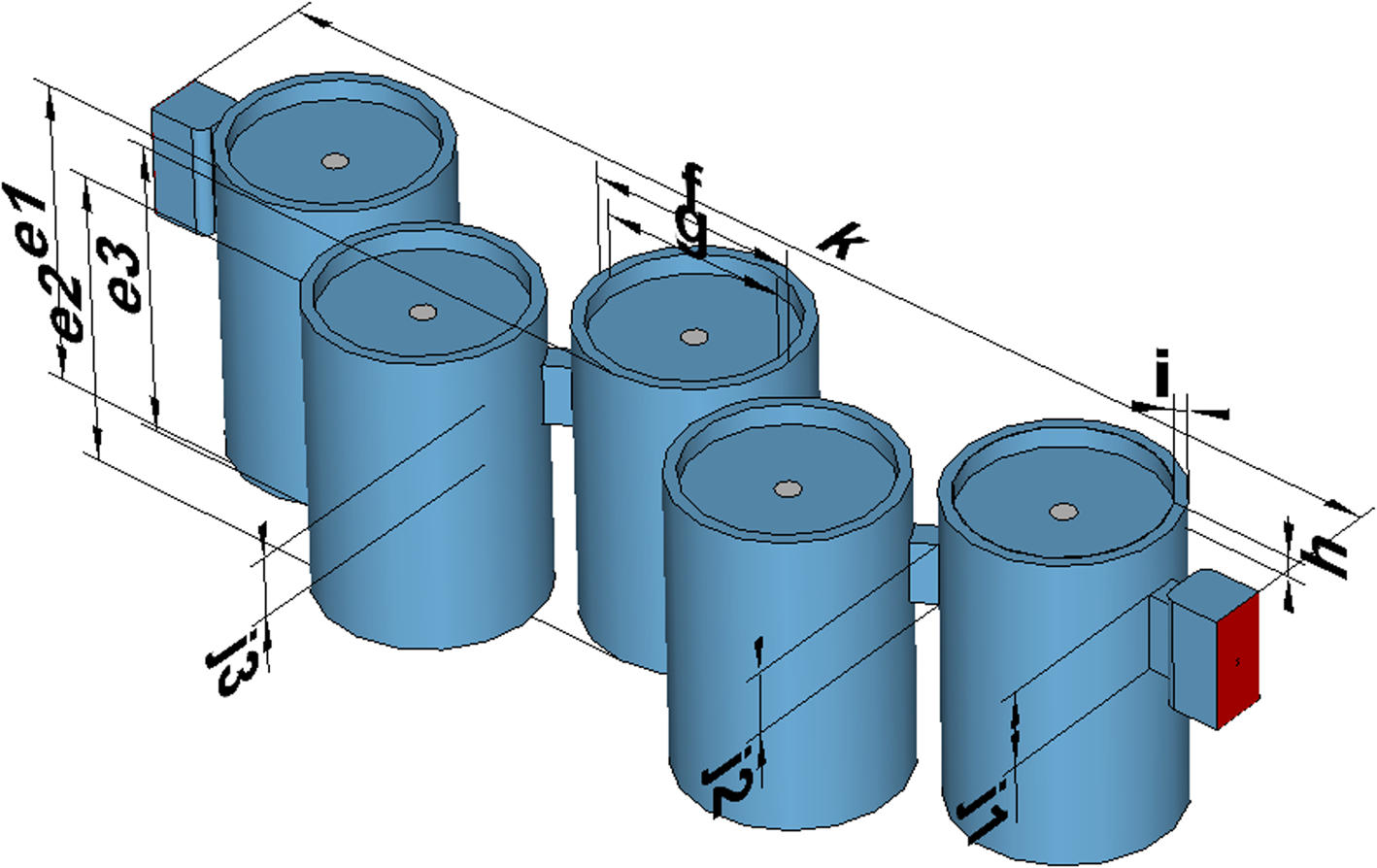
Fig. 5. CAD view of the proposed filter composed of five tunable resonators: e1 = 53.4 mm, e2 = 51.2 mm, e3 = 51.5 mm, f = 36 mm, g = 32 mm, h = 3.5 mm, i = 2 mm, j1 = 13.1 mm, j2 = 10.6 mm, j3 = 10.4 mm, and k = 202.6 mm.
For state 0, the lengths of the cavities (“e1” to “e3” dimensions) are used to obtain the required resonant frequencies. Initial coupling values are fixed using the “j” dimensions that define the coupling window height between the cavities. Considering the position of the perturbers and the EM field location (see Fig. 1), we can finely optimize the filter irises dimensions to provide the coupling laws and appropriate frequency behaviors of the tunable filters.
Every metallic part of the structure was manufactured in two halves out of aluminum by standard machining (manufacturing tolerances ±100 μm). Photographs of the devices are shown in Fig. 6.

Fig. 6. Left: machined aluminum housing of one tunable filter (bottom and top half parts); right: machined alumina perturbers that go inside the machined cavities (five perturbers per filter).
Measurements were made after a specific tuning process. Indeed, the two tunable filters must respect rigorous specifications in terms of rejection inside the bandwidth of the input filter (11.8–12 GHz); the filter pair responses must be as identical as possible inside the bandwidth of the overall diplexer to present an identical load for every frequency at the hybrid coupler ports. Both filters were also tuned in parallel using a four-port analyzer to obtain as identical responses as possible. The results are shown in Fig. 7 and detailed for both filters in each of the four configurations. We have here measured four cases: a first case that corresponds to state 0 (channel 1 BW = 140 MHz) and different cases where the required channel 1 bandwidth provided by the pair of tunable filters decreases down to 20 MHz. We wanted to test whether the minimum required bandwidth of 40 MHz (state 3) and even less was possible to achieve. This tuning step focused on obtaining an acceptable in-band and out-of-band symmetry of the tunable filters S parameters using tuning screws and their dielectric perturbers.

Fig. 7. Measured tunable filters (filter 1 on top, filter 2 on the bottom): (a) state 0 corresponding to channel 1 bandwidth (BW) ≈ 140 MHz (11.8–11.94 GHz) and a return loss of approximately 20 dB, (b) channel 1 BW ≈ 100 MHz (11.8–11.9 GHz), (c) channel 1 BW ≈ 60 MHz (11.8–11.86 GHz), (d) channel 1 BW ≈ 20 MHz (11.8–11.82 GHz). Simulated responses for the first and last cases are also provided.
Once the first response (i.e. for state 0) has been obtained, the perturber positions can be optimized independently to obtain the different cases shown in Fig. 7. This leads to obtaining non-Chebyshev responses, where the matching under 11.80 GHz is not responding to an objective. As the tunable filter response is cascaded with the input bandpass filter (11.8–12 GHz), there is no need to control the matching level for frequencies lower than 11.8 GHz. However, it should be possible to use inserts inside the coupling irises [Reference Arnold, Parlebas and Zwick7] or optimize the perturber shape to obtain a stable coupling factor over the translation [Reference Périgaud, Tantot, Delhote, Verdeyme, Bila, Pacaud, Carpentier, Puech, Lapierre and Carayon19]. However, the first solution requires the implementation of additional control commands and associates stepped motors, whereas the second one leads to complex shapes that are hard to obtain using CNC machining at reasonable fabrication costs.
Tuning screws were also implemented inside the coupling irises to compensate for the manufacturing tolerances. These post-fabrication tuning screws are not a part of the tuning system, and their positions remain fixed from one tuning state to another. We can see in Fig. 7 that for these different cases, a return loss better than 18 dB is achieved within the future bandwidth of channel 1 once these filters are inserted in the diplexer. The measured insertion loss of the first tunable filter is between 0.69 and 0.86 dB for the widest and narrowest BWs, respectively. Regarding the second tunable filter, the measured insertion loss is between 0.95 and 1.18 dB. We could expect 0.6 dB insertion losses for these tunable filters using low-loss alumina [Reference Di Marco, Drissi, Delhote, Tantot, Geffroy, Verdeyme and Chartier18] and applying a high conductivity plating on metallic parts.
The losses are slightly higher than expected in the simulations, but we can see a good matching between the simulated and measured results (Figs 7(a) and 7(d)). Therefore, the tunable filtering function that was required is achieved as intended, and we can proceed with the other components needed for the whole diplexer.
Hybrid-coupled reconfigurable diplexer
These two tunable filters are now associated with an input bandpass filter and two hybrid couplers. We first present the two mentioned parts and finally measure the whole diplexer behavior.
Input bandpass filter
We designed a TE011 mode 6th-order bandpass filter using cylindrical cavities. The TE011 mode is considered a good compromise between a high-quality factor and a correct spurious-free window of approximately 0.6 GHz at 12 GHz. The filter was then manufactured based on a standard machining (milling) process. The two halves of the input filter can be seen in Fig. 8, as well as the simulated and measured responses.

Fig. 8. Photo of the two halves of the machined input bandpass filter out of aluminum and a comparison between the measurement and simulation of its S parameters.
The measured bandpass for a return loss of 20 dB is 185 MHz (200 MHz in theory) at approximately 11.9 GHz. The filter's broad frequency response shows a spurious-free window of approximately 1700 MHz (10.9–12.6 GHz), sufficient for the expected prototype. The insertion loss is 0.65 dB, which is slightly higher than the expected 0.39 dB considering the aluminum housing's theoretical conductivity of 2 × 10⁷ S/m. The estimated Q-factor of this fabricated filter is approximately 4000. The probable sources of this extra loss come from the low conductivity of the steel tuning screws that have been used here and from the short length of the screw threads that added some radiative losses. The input filter is, however, satisfactory for the test of the tunable diplexer proof of concept.
Hybrid couplers
Over the 11.8–12 GHz bandwidth, the couplers must provide a coupling value of 3.0 ± 0.2 dB, isolation and matching values beyond 25 dB, and a phase difference between the coupled and direct paths as close as possible to 90°.
A technical overview of the existing coupler technologies causes us to use a ladder-type coupler. We observe [Reference Nam, Lee, Kwak and Lee13, Reference Cohn and Levy20] that the achievable bandwidth for this type of coupler easily exceeds the previously exposed requirements (up to 15% relative bandwidth for a requirement of 1.7%). This fact enables the hybrid coupler to be used at approximately its lowest cut-off frequency. The closed direct coupling and transmitted coupling values can be obtained in this manner, which directly affects the multiplexing stage performance. However, the lack of compactness of such devices in comparison with short-slot hybrids, for example, should be underlined.
Figure 9 displays a photograph of the manufactured hybrid coupler as well as its measured and simulated S parameters.

Fig. 9. Photo of the two halves of a machined hybrid coupler out of aluminum and a comparison between the measurement (solid lines) and simulation (dotted lines) of the two couplers S parameters.
The measured phase difference between the direct and coupled paths is between 92.2° and 89° and is close enough to the required specifications. Based on these measurements, we can expect to see between 0.1 and 0.2 dB of extra losses from each coupler when we measure the final losses in the diplexer channels. The major deviation observed is the shift toward the upper frequency of the coupler's S parameters compared to the simulated curves because of the manufacturing tolerances. This may cause asymmetrical behavior of the final diplexer that can now be tested.
Measurement of the hybrid coupled diplexer
The previous parts were assembled and then measured, as shown in Fig. 10.

Fig. 10. Photo of the whole diplexer consisting of the manufactured input filter and two identical hybrid couplers and tunable filters. The port numbering is the same as in Fig. 4.
Four states were measured: we had state 0, where we wanted to achieve a BW of 140 MHz for the lowest channel (channel 1) and 40 MHz for the highest (channel 2). A 20 MHz guard band is wanted for this state and all the other tested states. Alternatively, state 3 is the complementary configuration with a BW of 40 MHz for channel 1 and 140 MHz for channel 2. States 1 and 2 are intermediate cases that can be obtained between these two extreme configurations. Figure 11 and Table 1 provide the results of the measurement campaign of this proof of concept.

Fig. 11. Measured (states 0–3) S parameters of the whole diplexer. Top line: S 31 (channel 1) and S 41 (channel 2) for the four states. Middle line: S 11 for the four states (channel 1 and 2 bandwidths are displayed to help track their changes). Bottom line: S 32 for the four states.
Table 1. Measured performances under different operating conditions

The measured device shows satisfying functional properties with the possibility of splitting an overall bandwidth of approximately 200 MHz into two different bandwidths (two channels). The first channel bandwidth is 135–44 MHz (state 0–3), and the second channel bandwidth is 40–129 MHz (state 0–3). The measured bandwidth is defined using an ILMAX −1 dB criterion on the insertion losses of each channel. A bandwidth tuning ratio between 3.1 and 3.2 was then demonstrated.
Between states 0 and 3, the diplexer can also be continuously tuned, and intermediate states 1 and 2 provide a bandwidth of 110–69 MHz (states 1–2) for the first channel and a bandwidth of 61–112 MHz (states 1–2) for the second channel. The typical guard band is approximately 26 ± 7 MHz for the different measured states (the expected value was 20 MHz).
The measured insertion losses are between 1.65 and 2.46 dB. The return loss (S 11) is between 9.39 and 17.09 dB, and the isolation between channels is between 13.64 and 22.73 dB. A better surface roughness would sure help improve the loss of the different elements of the diplexer. However, the main issues are more directly related to manufacturing accuracy. Two improvements are then possible: first, a better centering of the coupler's frequency response at 11.9 GHz, greatly enhancing the final behavior of the diplexer and making the channel frequency responses more symmetrical. Second, a significant difficulty encountered during machining was the relatively high depth between the bottom of the upper half of the tunable filter, and it stopped. This critical height has generated this essential manufacturing tolerance through tool vibrations. The TE012 mode used is relatively insensitive to the mentioned tolerances. However, the simulations performed by taking into account this information showed that the TE013 mode that should be fixed at approximately 12.1 GHz (see simulations in Figs 7(a) and 7(b)) is not at the same frequency in all the cavities. Consequently, the six non-perfect cavities in the tunable filter generate random transmission zeros above 12 GHz (see measurements in Fig. 7) that lower channel 1 out of band isolation at a higher frequency and channel 2 return loss.
From the comparison in Table 2, we can see that the proposed tunable diplexer proof of concept has shown its potential with its high-level tuning ratio of the bandwidth. However, this solution deserves state-of-the-art manufacturing to limit the problems mentioned above and the use of better quality materials (low-loss ceramics and silver plating of the cavities) to show its full potential.
Table 2. Comparison between the different multiplexer implementations

Conclusion
A functionally tunable diplexer using the hybrid coupler multiplexing approach and quasi-low pass tunable filters has been presented. The principle of this diplexer consists of the frequency control of a filter pair, making their bandwidths overlap with the fixed input filter response (11.8–12 GHz).
The actuation system is based on a simple translation of identical dielectric perturbers, one per resonant cavity of the tunable filters. Thanks to dielectric perturbers, a high Q-factor can be maintained during frequency tuning within the input filter passband.
This tunable multiplexing technique can separate a bandwidth into two contiguous channels. The measurements have shown the possibility of multiplying the channel bandwidth by a factor of 3.2 and the possibility of continuously tuning the diplexer with different intermediate states. This multiplexer stage can also be cascaded to obtain more channels since the concept can be deployed to create more channels within a given passband.
As a proof of concept, the design remains simple, and state-of-the-art manufacturing techniques can increase device performance, such as better manufacturing tolerances, silver coating of the cavities, and the use of lower loss ceramics such as pure alumina. Optimizing performances and footprints while implementing more complex filtering functions should be the next step of our work on this subject.
Acknowledgements
This work was supported by the French Space Agency (CNES) through the “Filtres hyperfréquences à forts facteurs de qualité accordables continument” project and by Thales Alenia Space, Toulouse, France.
 Dr. Etienne Laplanche (S’17) was born in Guéret, France, 1994 and received his Master's degree from the Université de Limoges, France, in 2016. He received his Ph.D. degree in hyperfrequencies from the University of Limoges in 2019. His thesis subject was focused on high-Q tunable filters for space applications, and he is working in collaboration with the Centre National d'Etudes Spatiales and Thales Alenia Space France. He is currently working as a telecom satellite system designer in Thales Alenia Space, Toulouse.
 Dr. Olivier Tantot (53 years old) obtained his Ph.D. in electronics in 1994 from the University of Limoges, France. Since 1994, he has been a researcher at the “Institut de Recherche en Communications Optiques et Microondes”, Limoges. Since 1997, he has been an associate professor at the XLIM Laboratory of Limoges (France), and he is working on new characterization material methods for thin films or massive materials at low and high frequencies. He also has an interest in microwave tunable filters for space applications and additive manufacturing for RF.
 Dr. Nicolas Delhote (39 years old) received his Ph.D. degree in 2007 from the XLIM Research Institute and has been with XLIM since that date. He specializes in 3D manufacturing technologies to fabricate RF and millimeter wave passive components (filters, waveguides, and RF transitions) and tunable counterparts. He has particularly focused most of his activity on additive manufacturing technologies and materials for high-end applications (space telecommunications, airborne radar applications, and high-frequency wireless telecommunications). He has been the head of the MACAO group since 2016 (eight faculty members, 12 Ph.D. students, and postdoc).
 Pr Serge Verdeyme was born in France in June 1963. He received a Doctorate from the University of Limoges, Limoges, France, in 1989. Pr. Verdeyme is currently a Professor at XLIM, Laboratory of the CNRS and the University of Limoges, and works in the RF System department. His main area of interest concerns the design and the optimization of microwave components.
 Dr. Aurélien Périgaud was born in Limoges, France, in 1981. He received a Ph.D. degree from the XLIM Laboratory, University of Limoges, Limoges, France, in 2009. Dr. Périgaud is currently a Research Engineer at XLIM Laboratory, University of Limoges. His research activities are mainly dedicated to the packaging of millimeter-wave modules and the design of original resonators and filters.
 Dr. Damien Pacaud was born in France in December 1971. In 2001, he received a Ph.D. degree in Applied Mathematics and Scientific Computing from the University of Bordeaux 1, France. He joined the CEG Center in 1996 to develop powerful electromagnetic numerical techniques, and he joined IEEA (Paris) to develop RF software in 2000. Since 2001, he has been in charge of Filters and Multiplexers studies and developments for spatial applications at Thales Alenia Space, Toulouse, France. His main area of interest concerns optimization and computer-aided design (CAD) processes for novel passive microwave products.
 Dr. Ludovic Carpentier received a Ph.D. degree in Electrical Engineering from the University of Limoges, France, in 2012. He is currently a Research and Development Engineer in the French Space Agency (CNES) in Toulouse, France, where he is involved in the microwave passive components area.


