


I. INTRODUCTION
In recent years, the circularly polarized (CP) antenna has been highly demanded in many wireless applications such as navigation satellite system, radio-frequency identification system, and wireless local system [Reference Gao, Luo and Zhu1]. Compared with linear polarization, circular polarization has its inherent feature in reduction of unexpected losses caused by the polarization misalignment, thus provides good flexibility in the orientation angle between the transmitting and receiving antennas. In such case, there are many reported CP antennas with different advantages such as improved axial-ratio (AR) and impedance bandwidths [Reference Khidre, Lee, Yang and Elsherbeni2], enhanced radiation gain [Reference Zhang, Liu, Zhao and Fu3], and compact size [Reference Wong, Wong and Luk4]. However, these CP antennas often suffer from a narrow AR beamwidth, and can only radiate the good CP wave in the main radiation direction such as the broadside of a CP patch antenna [Reference Gao, Luo and Zhu1]. On the other hand, it is definitely required in many applications that good CP radiation be achieved in a wide angular range. For instance, CP antennas in the Global Positioning System need to be designed with a 3 dB AR beamwidth larger than 120° so as to improve the coverage communication area.
In the past two decades, a few effective approaches have been proposed to achieve such a wide AR beamwidth for CP antennas [Reference Jiang, Xue, Li and Ren5–Reference Luo, Chu and Zhu17]. Firstly, the ground plane of these CP antennas was appropriately reshaped in the format of a rectangular shell [Reference Jiang, Xue, Li and Ren5], a metallic cavity [Reference Ta and Park6, Reference Ta, Han, Park and Ziokowski7], or a pyramidal ground plane with a folded conducting wall [Reference Su, Huang and Lee8], resulting to achieve a 3 dB AR beamwidth of more than 130° over the operating band. However, aforementioned approaches based on the ground plane unfortunately enlarge the height of these antennas to above 0.09λ 0, leading to a poor low-profile property. Secondly, the dielectric layer could also be redesigned to enhance the AR beamwidth. In [Reference Bao and Ammann9], a wide 3 dB AR beamwidth of more than 165° was gained by stretching the substrate beyond the ground plane. By inserting a few discrete dielectrics into the air substrate of a patch antenna [Reference Currie, Antar, Petosa and Ittipiboon10], a widened 3 dB AR beamwidth of more than 126° was obtained. However, this approach may harmfully generate the unwanted surface waves, thus degrading the AR bandwidth and radiation pattern. In addition, CP antennas with improved radiation elements have gathered much attention in terms of enhancing the AR beamwidth. The helix antennas in [Reference Caillet, Clénet, Sharaiha and Antar11–Reference Ding, Wang and Xiong13] with different configurations were proposed to widen AR beamwidth, but they were difficult to be practically implemented due to their strict requirement in accurate fabrication, especially at high frequencies. In [Reference Choi, Lee and Lee14], a horizontal bowtie-shaped antenna with the vertically mounted top-hat elements produced a 3 dB AR beamwidth of 140°. In [Reference Ta, Choo, Park and Ziolkowski15], a novel crossed dipole was presented to increase the 3 dB AR beamwidth up to 110°. In [Reference Latif and Shafai16], the parasitic ring was rotated around the driven ring to generate a wide AR beamwidth up to 147°. Unfortunately, all of these reported CP antennas suffered from complicated geometry of multi-radiator and high profile.
Apart from the techniques mentioned above, a novel approach is recently presented in [Reference Luo, Chu and Zhu17] by forming up two orthogonal pairs of parallel dipoles in a square contour. By properly selecting the spacing between two parallel dipoles, the 3 dB AR beamwidth at the central frequency was tremendously extended to 126°. As we all know, the slot antenna on an infinite ground plane can be regarded as being complementary to the dipole [Reference Yoshimura18]. Thus, the approach can also be applied in the slot antenna. The comparison of the proposed antenna and other CP antennas are shown in Table 1.
Table 1. Comparison between the proposed antenna and other CP antennas.

In this paper, a low-profile CP slot antenna with two orthogonal pairs of parallel slots is proposed and designed to obtain a wide AR beamwidth. The two pairs of parallel slots are etched symmetrically onto a square ground plane, and they are excited in the same amplitude with 90° phase difference through proper design of the feeding network. Our theoretical study depicts that a wide AR beamwidth of the proposed antenna on an infinite ground plane can be obtained when the distance between two parallel slots is selected as 0.4λ 0. Later on, the effect of a finite ground plane size on the radiation pattern is extensively studied to demonstrate how the AR beamwidth varies with respect to the size of the finite ground plane. Finally, the proposed antenna is fabricated on a finite ground plane with a single dielectric substrate. The measured 3 dB AR beamwidth achieves as large as 126°, while |S 11| < −16 dB, AR < 3 dB, and gain>4 dBic are gained in a frequency range from 3.33 to 3.47 GHz.
II. OPERATING PRINCIPLE OF THE PROPOSED ANTENNA
Figures 1(a) and 1(b) show the schematic of the CP printed dipole antenna in [Reference Luo, Chu and Zhu17] and the slot antenna proposed in this work, respectively. Their respective radiating elements are the four dipoles and four slots. For the CP dipole antenna [Reference Luo, Chu and Zhu17], the electric current flows along the four dipoles. For the proposed slot antenna, the electric field is distributed along the four radiating slots as the equivalent magnetic current. In our analysis, the slot antenna is placed in the XY-plane. One pair of parallel slots is arranged in the X-axis, whereas another pair of parallel slots is in the Y-axis. Besides, the length and width of four identical radiating slots are denoted by L and W, respectively, and the spacing between two parallel slots is expressed as D.

Fig. 1. Schematic representation of wide-beamwidth CP antennas and their radiation patterns. (a) Printed dipole antenna. (b) Slot antenna. (c) Radiation patterns of the CP dipole. (d) Radiation patterns of the CP slot antenna.
Now, let us start with the analysis of radiation patterns for the proposed slot antenna on an infinite ground plane at first. When the width of the slot (W) is much narrower than the free-space wavelength (λ 0), that is, W ≪ λ 0, the electric field on each of these four slots can be assumed to be perpendicularly oriented across these narrow slots with no longitudinal electric field component, and its intensity varies as a cosine function along the slot. Based on the antenna theory in [Reference Garg, Bartia, Bahl and Ittipiboon19], the far-zone normalized electric field component in the XZ-plane, radiated by a pair of parallel slots along the X-axis, can be deduced as
 $${E_\varphi} (\theta ) = \displaystyle{{\cos \left( {kL \times \sin (\theta )/2} \right)} \over {{{\left( {kL \times \sin (\theta )/\pi} \right)}^2} - 1}} \times \cos (\theta ),$$
where k = 2π/λ 0 is the wave number in free space.
Similarly, for a pair of parallel slots along the Y-axis, the far-zone normalized electric field component in the XZ-plane can be derived as
 $${E_\theta} (\theta ) = \cos \left( {kD \times \sin (\theta )/2} \right).$$
In order to obtain the perfect CP radiation with ∠E θ –∠E φ = ±90° at the broadside, the vertical and horizontal paired-slots need to be excited in the same amplitude with 90° phase difference. With this arrangement, the AR varies as a function of the polar angle (θ) in the XZ-plane such that
 $${\rm AR}\left( \theta \right) = \left \vert {20 \times {{\log} _{10}}\left \vert {\displaystyle{{{E_\theta} (\theta )} \over {{E_\varphi} (\theta )}}} \right \vert} \right \vert. $$
The |E θ | and |E φ | radiation patterns of the printed CP dipoles are plotted in Fig. 1(c) based on [Reference Luo, Chu and Zhu17]. By using (1) and (2), the far-zone electric field components, |E θ | and |E φ |, of the slot antenna in the XZ-plane are calculated as shown in Fig. 1(d). Note that the |E θ | radiation pattern is similar to the |E φ | pattern of its dipole counterpart. Meanwhile, the |E φ | pattern of the slot antenna and |E θ | pattern of its dipole counterpart are also similar to each other.
In this work, each slot is designed with the length of L = 0.5λ 0 as usual. As can be seen in Fig. 2, the |E φ | radiation pattern (black-line) keeps almost constant regardless of varied spacing D, since the |E φ | expression in (1) is not a function of D. In contrast, the |E θ | radiation pattern (green-line) and AR (red-line) beamwidth are varied dramatically as D increases from 0.2λ 0 to 0.6λ 0. It can be understood from (2) and (3) that |E θ | and AR are highly dependent on the spacing D.

Fig. 2. Calculated |E θ |, |E φ | radiation patterns and 3 dB AR in the XZ-plane with varied spacing D. (a) D = 0.2λ 0. (b) D = 0.4λ 0. (c) D = 0.6λ 0.
More specifically, as D = 0.2λ 0, the beamwidth of the |E θ | radiation pattern in Fig. 2(a) is wider than that of |E φ | radiation pattern. Using equation (3), the calculated 3 dB AR beamwidth is found to be extremely narrow in a range of θ from −43 to 43°. When the spacing D increases to 0.4λ 0, the beamwidth of the |E θ | radiation pattern decreases dramatically as illustrated in Fig. 2(b), and it becomes almost the same as the |E φ | pattern in a wide range of θ from −60 to +60°. Hence, the 3 dB AR can be further enlarged to cover a wide range of the polar angle from −70 to 70°. In Fig. 2(c), as D reaches to 0.6λ 0, the beamwidth of the |E θ | pattern continues to decrease and becomes narrower than that of |E φ | pattern. Thus, the 3 dB AR beamwidth becomes narrow in the polar axis from −30 to 30°. To summarize these findings, Table 2 is tabulated to quantitatively depict the value of 3 dB AR beamwidth as the spacing D varies from 0λ 0 to 0.9λ 0. In final, it can be found that a maximum 3 dB AR beamwidth of about 140° is obtained at D = 0.4λ 0.
Table 2. The 3 dB AR beamwidth versus varied spacing D.

III. ANTENNA DESIGN AND IMPLEMENTATION
Based on the above analysis, a slot antenna with the wide AR beamwidth is designed on a dielectric substrate with the relative permittivity of 2.2 and the thickness of h = 3.18 mm as shown in Fig. 3. A feeding network is formed on top of the substrate to properly feed the proposed CP antenna with four radiating slots, and a ground plane with the size of G × G is selected at the bottom surface of the substrate. Besides, two pairs of slots with the same length of L and width of W are etched symmetrically onto the ground plane for radiation. In this design, the slot is slightly shorter than 0.5λ 0 in length in order to take into account the inductive effect of the slot line short-circuited ends. With reference to the results depicted in Fig. 2 and Table 1, the spacing D between two parallel slots is chosen as about 0.4λ 0 towards the widest AR beamwidth.
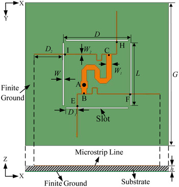
Fig. 3. Configuration of the proposed CP antenna with feeding network.
In the following, a 1–4 probe-to-microstrip feeding network with equal amplitudes and quadrature phase difference between output ports is designed to achieve the CP radiation at the broadside direction, i.e. Z-axis in Fig. 3. Firstly, an input impedance of 200 Ω for a slot is obtained at the resonant frequency of 3.4 GHz by selecting the strip width (W 2), feeding point (D 1), and slot width (W) properly. These impedances (200 Ω) of the slots are then considered as the load impedances at the four output ports (E, F, H, and I) of a 1–4 microstrip feeding network.
With reference to antenna structure in Fig. 3, it is required the input signal at Port A (coaxial probe) to be divided into four-way output signals at Ports E, F, H, and I with equal amplitude and 90° phase difference. Based on the network theorem in microwave engineering [Reference Pozar20] and the above constraints, the 1–4 microstrip feeding network can be designed as depicted in Fig. 4. It can be seen that the input signal from Port A is split into two ways, i.e. A to B and A to C, in equal amplitude and 180° phase difference. The characteristic impedances of microstrip line in these two ways are set as 100 Ω, aiming to match well the input Port A. Besides, the path difference between A to B and A to C is about λ g/2 (λ g is the guided-wavelength), thus allow output signals along these two paths to have the same amplitude and 180° phase difference. The impedances along the four output paths (B to E, B to F, C to H, and C to I) are set as 200 Ω in order to match well with the input impedance of the radiating slot at its resonance, and the path difference about λ g/4 is employed to produce 90° phase difference. Finally, this designed feed network is utilized to provide two pairs of equal-amplitude signals with 90° phase difference at the output ports of E, F, H, and I, respectively. Compared to the feeding network in [Reference Luo, Chu and Zhu17], the feeding network proposed herein is simple in geometrical structure and straightforward in the design procedure.

Fig. 4. Equivalent transmission-line topology of the feeding network.
In Section II, the analysis of our proposed slot antenna was executed under the ideal assumption of an infinite ground plane. In practical implementation, the overall size of the ground plane is definitely finite, so the induced equivalent magnetic currents on the finite ground plane edges will affect the radiation pattern of an antenna [Reference Namiki, Murayama and Ito21, Reference Bokhari, Mosig and Gardiol22]. Figure 5 depicts the simulated 3 dB AR beamwidth of the proposed antenna as a function of the finite ground size G varying from 100 to 200 mm. When G is enlarged from 100 to 160 mm, the beamwidth under AR < 3 dB is increased from 82 to 126°. Beyond G = 160 mm, the 3 dB AR beamwidth falls down slightly. If G is large enough, the 3 dB AR beamwidth tends to approach 140°, which corresponds to the case of an infinite ground plane.

Fig. 5. The 3 dB AR beamwidth of the proposed CP antenna in the XZ-plane with varied ground plane sizes.
To explain the behavior of AR beamwidth in detail, the AR beamwidth at G = 120, 160, and 200 mm against the θ is further studied and the relevant results are plotted in Fig. 6. At G = 120 mm, the AR value smoothly varies with respect to θ, and the 3 dB AR beamwidth becomes relatively narrow of about 86°. When G is increased to 160 mm, the beamwidth (AR < 3 dB) reaches to 126°. However, the AR curve has the ripple due to the unexpected edge diffraction from finite ground plane. At G = 200 mm, the 3 dB AR beamwidth slightly decreases to about 109°. Thereafter, of the three listed cases, G = 160 mm is the most suitable value to achieve a wide AR beamwidth. Till now, the proposed slot antenna in Fig. 3 with finite ground plane can be designed for practical realization and Table 3 tabulates all its dimensional parameters.

Fig. 6. The 3 dB AR in the XZ-plane with varied ground plane size G. (a) G = 120 mm. (b) G = 160 mm. (c) G = 200 mm.
Table 3. Dimensions of the proposed antenna in Fig. 3.

IV. RESULTS AND DISCUSSION
To confirm the design performance, the proposed antenna was simulated with the EM simulator IE3D, and was fabricated following these design parameters listed in Table 3. Figure 7 shows the top- and bottom-view photographs of the fabricated CP antenna prototype. The return loss is measured using the Agilent N5230A Vector Network Analyzer. The whole radiation pattern, including the AR and gain, are experimentally evaluated with the near-field SATIMO antenna test system.

Fig. 7. Photographs of the fabricated antenna. (a) Top view. (b) Bottom view.
Figure 8 depicts the simulated and measured AR as a function of θ at the central frequency of 3.4 GHz in the XZ-plane. Under the 3 dB AR definition, the measured AR beamwidth has reached 126°, which matches well with the simulated one. The slot antenna radiates the left- and right-hand circular polarizations, in short, LHCP and RHCP, below and above the horizontal plane as shown in Fig. 3, respectively. The simulated and measured radiation patterns in the XZ and YZ planes at 3.4 GHz are depicted in Fig. 9, the bidirectional CP radiation patterns with the low cross-polarization are obtained for the proposed antenna, which can be well used for applications such as microwave sensor networks and broadcasting base stations [Reference Shen, Lu and Cao23, Reference Lu and Wang24].

Fig. 8. Simulated and measured AR of the proposed antenna in Fig. 7 with respect to the θ at 3.4 GHz.

Fig. 9. Simulated and measured radiation patterns at 3.4 GHz.
The simulated and measured results in Figs 10(a)–10(c) show the peak gain, AR, and return loss against frequency. In the operating band of 3.33–3.47 GHz, the antenna has achieved the expected CP radiation performance such as AR < 3 dB, |S 11| < −16 dB, and gain > 4 dBic.

Fig. 10. Simulated and measured antenna parameters with respect to frequency. (a) Gain. (b) AR. (c) |S 11|.
V. CONCLUSION
In this paper, a low-profile CP slot antenna with widened AR beamwidth is proposed, designed, and measured. The antenna consists of two pairs of slots and a simple feed network. To achieve a wide AR beamwidth, the principle of CP radiation of the four slots on an infinite ground plane is analyzed firstly. Then, a 1–4 probe-to-microstrip feeding network is designed to excite the two orthogonal paired-slots with the same amplitude and quadrature phase difference. Owing to the diffraction from the edge of the finite ground plane in practice, the 3 dB AR beamwidth variation with the ground plane size is further investigated. In final, the proposed CP antenna on the finite ground plane is fabricated and measured, all of the measured results such as the gain, returned loss, AR bandwidth, and radiation patterns are in good agreement with the simulated ones. Particularly, the wide 3 dB AR beamwidth of 126° and low-profile property with the height of 0.036 free-space wavelength are achieved. Thus, the proposed antenna is believed to be a good candidate of CP antennas with wide AR beamwidth as needed in wireless communication. Thus, the antenna can be well applied in the wireless communication system such as International Mobile Telecommunications-Advanced.
ACKNOWLEDGEMENTS
This work was supported by the Multi-Year Research Grants (MYRG2014-00126-FST and MYRG2015-00010-FST) from the University of Macau, Macau SAR, China. The authors would like to thank Mr. Xiao Zhang, University of Macau, for his kind assistance in antenna test and beneficial discussion.
 Neng-Wu Liu was born in Changde, Hunan, China. He received the B.S. and M.E. degrees in Electronic Engineering from Xidian University, Xi'an, Shaanxi, China, in 2012 and 2015, respectively. Currently, he is working toward the Ph.D. degree in Electrical and Computer Engineering from the University of Macau. His research interest focuses on wideband antennas and circularly polarized antennas.
 Lei Zhu received the B.Eng. and M.Eng. degrees in Radio Engineering from the Southeast University, Nanjing, China, in 1985 and 1988, and the Ph.D. degree in Electronic Engineering from the University of Electro-Communications, Tokyo, Japan, in 1993. From 2000 to 2013, he was an Associate Professor with the Nanyang Technological University, Singapore. Since August 2013, he has been a Full Professor with the University of Macau, Macau SAR, China. Since September 2014, he has been serving as the Head of Department of Electrical and Computer Engineering, University of Macau. His research interests include microwave circuits, guided-wave periodic structures, antennas, and computational electromagnetic techniques. He was the Associate Editor for the IEEE Transactions on Microwave Theory and Techniques (2010–2013), and the IEEE Microwave and Wireless Components Letters (2006–2012). He was the recipient of the 1997 Asia–Pacific Microwave Prize Award.
 Wai-Wa Choi was born in Macau in 1970. He received the B.Sc., M.Sc., and Ph.D. degrees in Electrical and Electronics Engineering from the University of Macau, Taipa, Macao, China, in 1993, 1997, and 2008, respectively. From 1993 to 1995, he was with the Institute of Systems and Computer Engineering (INESC), Lisbon, Portugal, as a Research Assistant. Since 1995, he has been with the University of Macau, where he is currently an Associate Professor in the Department of Electrical of Computer Engineering. He has authored or coauthored over 40 internationally refereed journal and conference papers. His research interests are in the areas of microwave active and passive circuits, smart antennas, radar, and radio-frequency identification system etc. Dr. Choi was the Chair of IEEE Macau AP/MTT Joint Chapter in 2015. He has been a reviewer for the IEEE Transactions on Microwave Theory and Techniques, IEEE Transactions on Industrial Electronics, IEEE Microwave and Wireless Components Letters, and IEEE Antennas and Wireless Propagation Letters.


