Introduction
Multiple-Input Multiple-Output (MIMO) technology is considered as a core technology for next generation mobile communication. In order to increase network throughput, communication capacity, and coverage without requiring additional bandwidth, MIMO technology can be utilized [Reference Gunduz, Khojastepour, Goldsmith and Poor1]. Nevertheless, when MIMO antenna is installed in the limited place, the distance between antenna elements is close, it may cause a strong mutual coupling. As a result, the size of the MIMO antenna is relatively large, and the throughput of the communication is decreased [Reference Xu, Sfar and Blum2, Reference Lu, Hui and Bialkowski3].
In recent years, several antenna designs have been proposed in MIMO terminals. However, there is a strong coupling problem caused by the close distance of the MIMO antenna, which may greatly affect the performance of the antenna. For example, antenna gain and radiation efficiency may be reduced. In order to overcome the above problems, several methods and researches are devoted in this field. For instance, in order to reduce the mutual coupling for a planar MIMIO antenna, [Reference Cheung, Li, Wu, Zhou and Wang4, Reference Chiu, Cheng, Murch and Rowell5] provide a defected ground structures with two resonances. Rahmat-Samii and Mosallaei and Li and Feresidis propose electromagnetic band-gap structures in [Reference Rahmat-Samii and Mosallaei6, Reference Li and Feresidis7]. Literatures [Reference Okuda, Sato and Takahashi8, Reference Sato, Koyanagi, Ogawa and Takahashi9] provide meandering branch-shape to implement the decoupling. In [Reference Gil and Fernández-García10], the authors analyze the influence of the three structures of split-ring resonator, non-bianisotropic split-ring resonator, and spiral resonator on the decoupling. In addition, a capacitive coupling between the π-line and the two curved stubs is adopted to form the decoupling network [Reference Zhang, Xue, Cao and Ding11]. Furthermore, a novel diamond-shaped patterned ground resonator is used to achieve the decoupling [Reference Wu, Cheung, Li and Yuk12]. Two bent slits are etched on the ground plane to reduce coupling in [Reference Li, Chu and Huang13]. A T-shaped strip on the ground is employed to further improve the isolation for low frequency [Reference Toktas14]. Moreover, in [Reference Wang and Du15], it reports a neutralization line technique to achieve decoupling. Then authors of [Reference Xu, Zhang, Shi, Liu, Wen and Wang16] presented the use of 3D anisotropic metamaterials to implement the decoupling structures. The above literatures basically cover the 2G, 3G, and 4G band, but the latest proposed 5G has not yet been covered. Now 5G is the most popular research period. It has the advantages of high performance, low latency, and high capacity characteristics. It is the trend of development in the field of mobile communications.
In this paper, we present a compact dual-element printed MIMO antenna that is developed to support the GSM900, PCS, LTE2300, and 5G bands. The proposed antenna is implemented using two symmetrical printed monopole arrays. Compared with a single antenna, two antennas increase the gain of the antenna. This paper introduces a new decoupling structure, consisting of four inverted-L branches etched on its ground plane. It can reduce the mutual coupling between two antenna elements. Section 2 details the MIMO antenna configuration. In Section 3, we will discuss the simulated and measured results. At the same time, the proposed decoupling element is described and analyzed in detail.
Antenna design
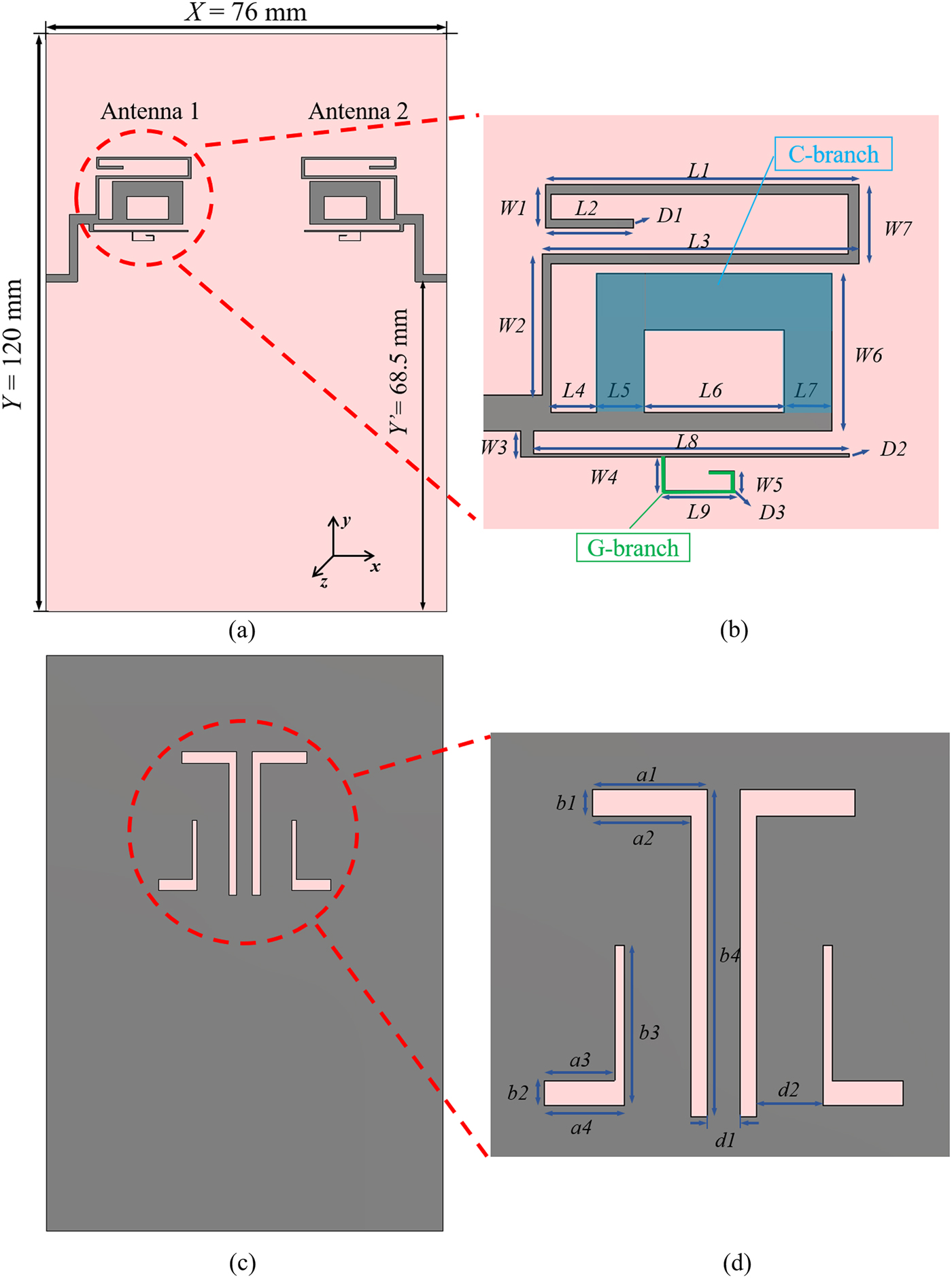
Figure 1 shows the structure of the proposed multiband MIMO antenna. This MIMO antenna consists of feed line, two bent radiating antennas, and decoupling element. In this paper, a 1 mm-thick FR-4 (lossy) (εr = 4.3, tanδ = 0.025) is used as the substrate. The size of the substrate and ground plane is X × Y = 120 × 76 mm2. The metal we used here is copper whose conductivity is σ = 5.8 × 10⁷S/m and thickness is 0.05 mm.

Fig. 1. (a) Top view of the proposed antenna, (b) an enlarged view of the radiation elements, (c) bottom view of the proposed antenna, (d) an enlarged view of the decoupling elements.
Figure 1(a) shows the top view of the proposed MIMO antenna. Two radiating patches are symmetrically arrayed on left and right sides of the substrate. The antennas 1 and 2 have the same structure, thus they can operate at the same frequency. In order to maximize transmission power, impedance matching is required. Therefore, it is necessary to adjust the impedance of the antenna feed to 50Ω to match the standard SMA connector. In this model, the resonant frequency and the resonance strength of the MIMO antenna are mainly dependent on the parameters of the individual bent lines. Different branches make them have different electrical lengths. Therefore, the parameters of each bent line are optimized by simulation so that the return loss at the desired resonant frequency becomes less than −10 dB. The specific sizes of the proposed antenna are shown in Fig. 1(b) and listed in Table 1.
Table 1. Specific parameters of the proposed MIMO antenna (unit: mm)

In order to cover the 5G band recently proposed by the Ministry of Industry and Information Technology of China, the branch L 8 and its next G-branch (green lines in the picture) of the antenna are added. Hence, each printed monopole antenna element can generate four resonant modes at 0.93, 1.86, 2.32, and 4.87 GHz simultaneously. Besides, the size of L 1 and W 1 mainly affect the resonant frequency at 0.93 GHz. Moreover, the frequency at 1.86 GHz strongly depends on branch L’ (L ′ = L 4 + L 5 + L 6 + L 7) and C-branch (blue parts in the picture) where W 6 is located. The frequency adjustment at 2.32 GHz mainly counts on branches L 2 and L 3.
Since these two antennas locate so close to each other, there is a strong coupling between them. The distance between the two antenna elements is 3λ GSM900, 1.5λ PCS, 1.2λ LTE2300, and 0.18λ 5G of the four resonance point medium, respectively. In order to reduce the mutual coupling between them, we introduce an original decoupling element. This decoupling element, consisting of two symmetrical inverted-L branches etched on the ground plane, which is on the bottom layer of the substrate. This structure is shown in Fig. 1(c), and the specific size is shown in Fig. 1(d). The distance between the two symmetrical inverted-L structures is 3 and 18.2 mm, respectively. The initial size of the decoupling structure is determined according to the formula  $\lambda _g = c/(f\cdot \sqrt {\varepsilon _r} )$. Decoupling can be achieved by adjusting the width and length of the inverted L-shaped structure. Through simulation, the relevant sizes are continuously adjusted and the final determination of the specific parameters of each part is also listed in Table 1. The parameter b 4 of the larger inverted-L structure mainly affects the coupling at 2.32 GHz. While decoupling at 4.87 GHz mainly depends on modifying the size of b 3 and a 4 of the smaller inverted-L branch. Through fine tuning, high isolation has been achieved for the MIMO antenna. The proposed MIMO antenna system with decoupling elements was simulated and optimized using CST Microwave Studio.
Simulated and measured results
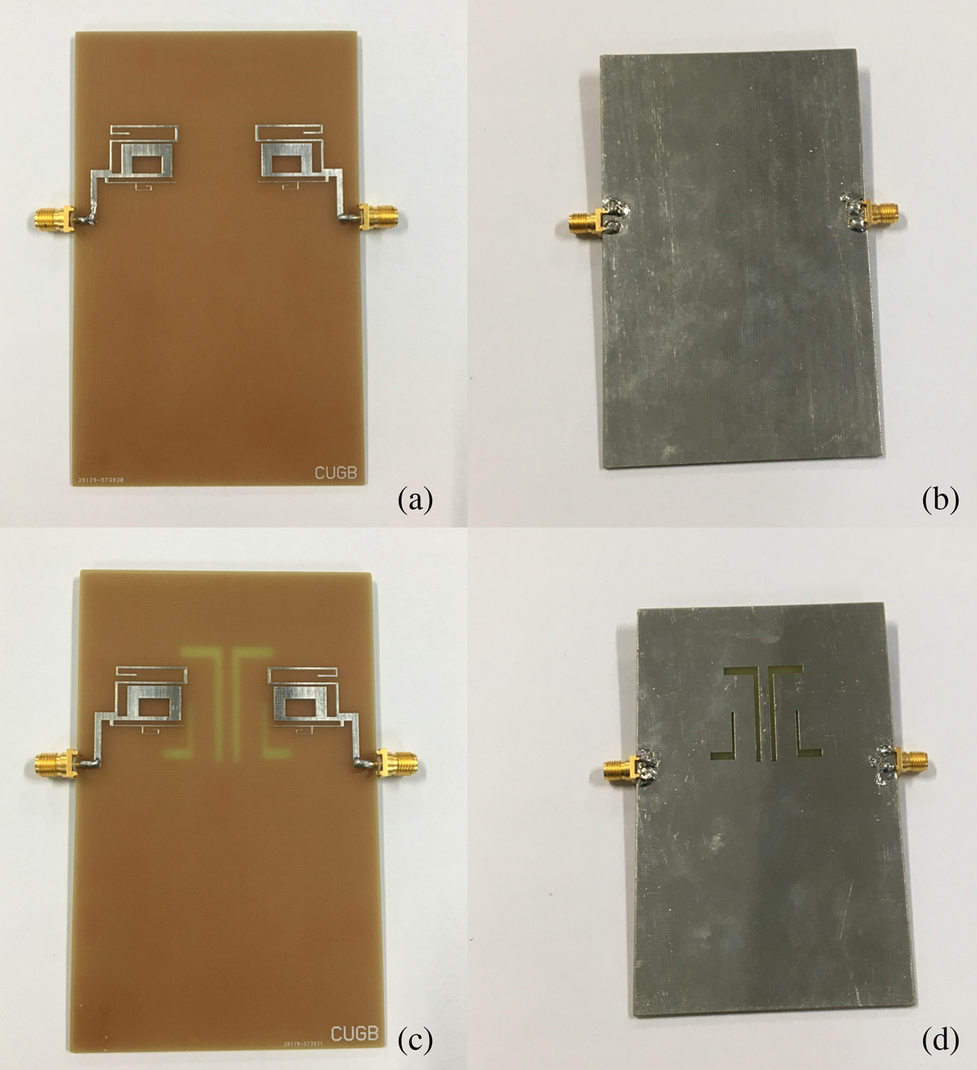
In this part, we will discuss the simulated and measured results. To validate the simulation, a prototype of the proposed multiband MIMO antenna was fabricated according to the optimized dimensions. It was measured using vector network analyzer (Rohde & Schwarz ZNB8). In the experimental measurement, the proposed MIMO antenna is fabricated on a printed circuit board. The test diagram is shown in Fig. 2. The photograph of the fabricated antenna prototype is shown in Fig. 3. Figures 3(a) and 3(b) show the top and the bottom of the original antenna. Figures 3(c) and 3(d) give the top and the bottom views of the decoupled antenna.
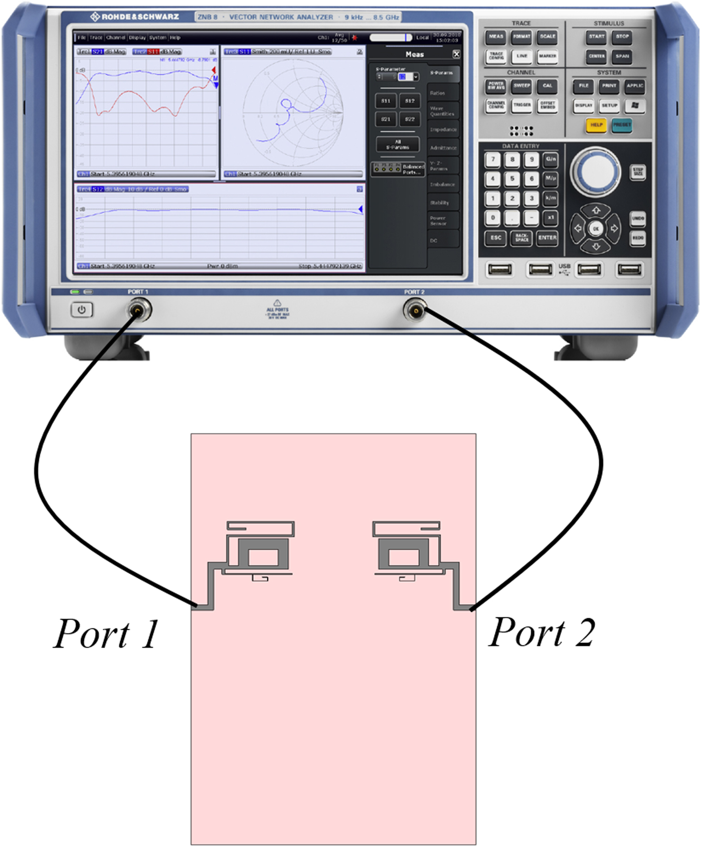
Fig. 2. Experimental test schematic (using Rohde & Schwarz ZNB8).

Fig. 3. (a) Top view of the original antenna, (b) bottom view of the original antenna, (c) top view of the decoupled antenna, (d) bottom view of the decoupled antenna.
S-parameters
The simulated and measured S-parameters of the proposed MIMO antenna configuration are shown in Fig. 4. As can be seen from Fig. 4, these results are in good consistency. It indicates that the simulated model is reasonable. There are some deviations between the measured results and the simulated results, which may be due to the difference between the simulation accuracy and the actual test, as well as the interference of noise in the non-anechoic chamber test environment. Since the structure of the antenna is relatively symmetrical, |S 11| = |S 22|, we only give the curve of |S 11|. In addition, according to the principle of reciprocity antenna, |S 21| = |S 12|, it only shows |S 21| in Fig. 4. Since the effect of the decoupling structure on the return loss S 11 of the antenna is not significant, only the simulated and measured results of the decoupling antenna |S 11| in dB are shown in Fig. 4(a). The operation bands and the frequency range of the proposed antenna are listed in Table 2.

Fig. 4. (a) Simulated and measured S 11 of antenna, (b) simulated S 21 of antenna with/without decoupling elements, (c) measured S 21 of antenna with/without decoupling elements.
Table 2. The operation bands and frequency range of the proposed antenna

It can be also seen from Fig. 4 that the designed antenna has a better S-parameter at the corresponding frequency band and return loss |S 11| can basically reach below −10 dB. Since the loss of the dielectric board FR4 is large, the |S 21| of the antenna is lower. Due to machining errors, test instrument accuracy and other reasons, the measured results are slightly different from the simulated results, but are still within the coverage of the frequency band. The return loss |S 11| can also reach below −10 dB. It can be noted from Figs 4(b) and 4(c) that after increasing the decoupling element, coupling level |S 21| dropped significantly at 5G frequency band. Moreover, the isolation of the measured results can be increased at least 5 dB.
Radiation patterns
In order to have a further study of the proposed MIMO antenna with decoupling elements, its performance is discussed in this part. Since the antenna is located in the x-y plane, the radiation energy of the MIMO antenna is mainly focused in the +z direction. To further confirm this point, Fig. 5 shows the 2D radiation pattern of the E-plane (x-z plane) and Fig. 6 shows the 2D radiation pattern of the H-plane (y-z plane) at four operating frequency, respectively. Because the decoupling element has no effect on the radiation, the radiation pattern before and after the improvement does not change much. Hence, the radiation pattern of the original antenna is not shown. Figures 5(a)–5(d) show simulated radiation patterns of modified MIMO antennas on the E-plane at 0.93, 1.86, 2.32, and 4.87 GHz, respectively. Figure 6 shows the simulated radiation pattern of the improved MIMO antenna with four resonance points at the H-plane. From Fig. 5, it can be noticed that the proposed antenna has a strong radiation energy in the z-direction. These results are consistent with our judgment.
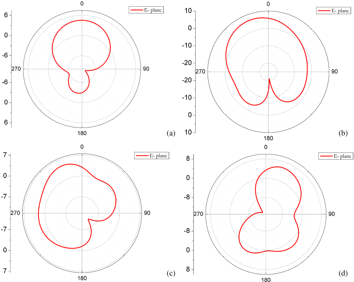
Fig. 5. (a) E-plane at 0.93 GHz, (b) E-plane at 1.86 GHz, (c) E-plane at 2.32 GHz, (d) E-plane at 4.87 GHz.
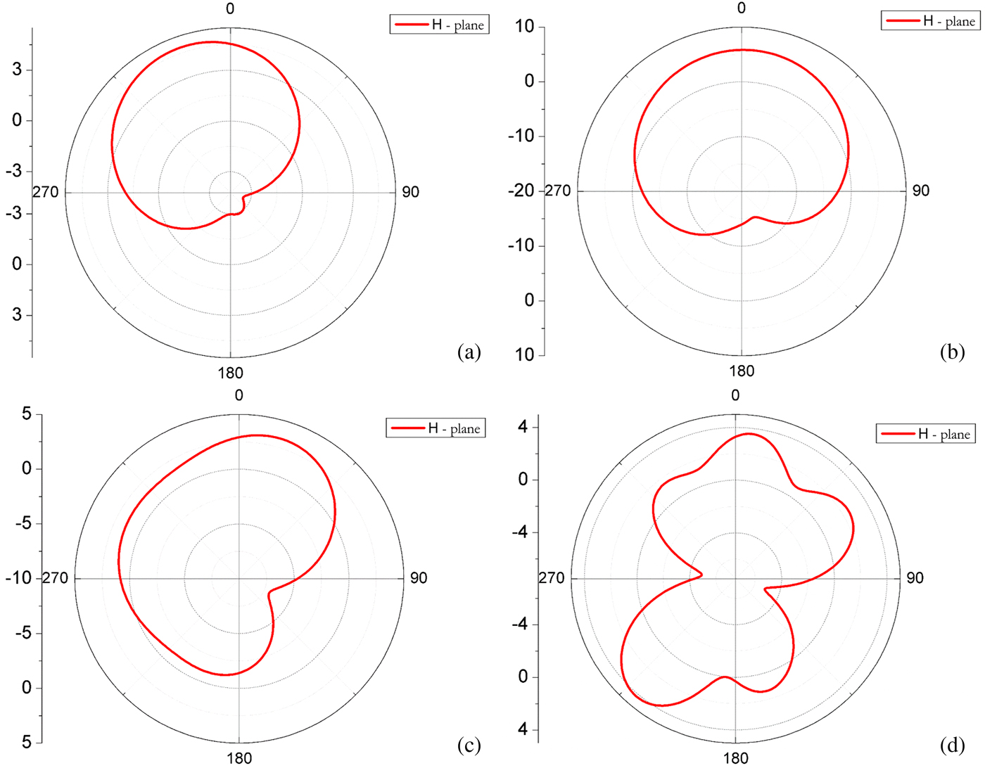
Fig. 6. (a) H-plane at 0.93 GHz, (b) H-plane at 1.86 GHz, (c) H-plane at 2.32 GHz, (d) H-plane at 4.87 GHz.
The simulated peak gain values of original antenna are 4.864 dBi at 0.93 GHz, 6.587 dBi at 1.83 GHz, 5.803 dBi at 2.322 GHz, and 7.254 dBi at 4.878 GHz, respectively. Correspondingly, the radiation gain values of decoupling antenna are 4.829, 6.605, 5.385, and 5.539 dBi. Based on the above comparison, it can be known that increasing the decoupling structure does not change the performance of the antenna such as the operating frequency band, radiation pattern, and gain. So it does not affect the performance of the antenna. Therefore, the decoupling structure can achieve a reduction in electromagnetic coupling between two antenna elements without changing the antenna size.
Surface current
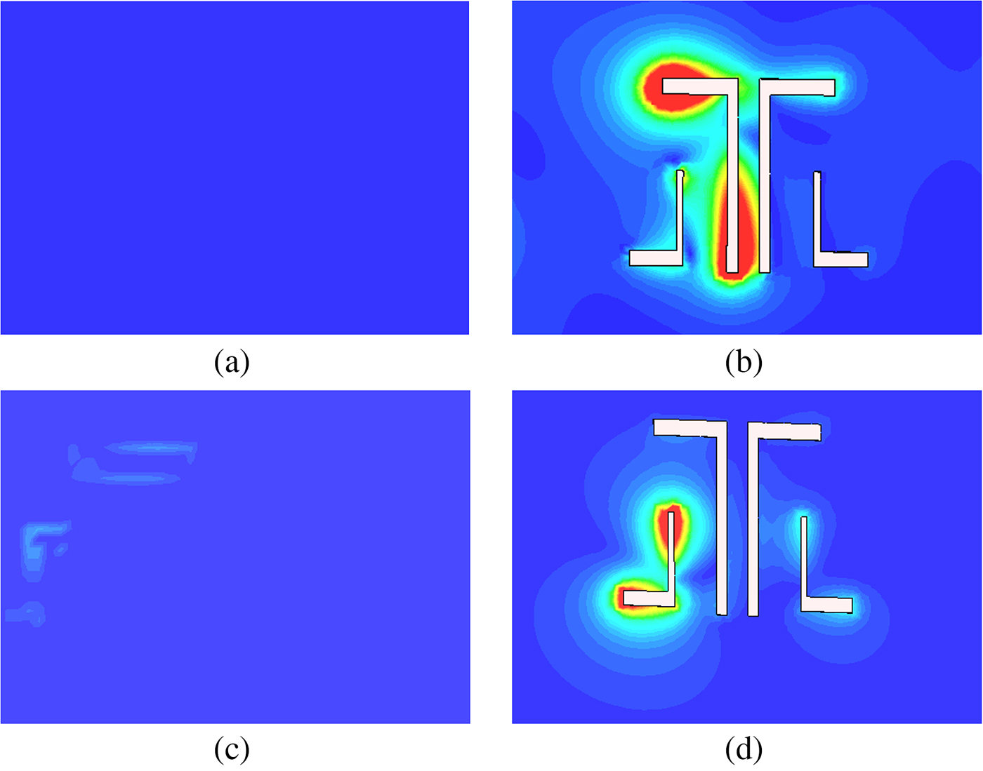
In this paper, in order to reduce the mutual coupling between the two antenna elements, a decoupling structure is etched on the ground plane, which consists of four inverted-L branches. Further analysis of the working mechanism of the decoupling element has been studied here. The effect of the decoupling element on the MIMO antenna is analyzed through simulation, as shown in Fig. 7. By slotting the ground plate, the path of the current is changed to a certain extent, so that energy is consumed and the degree of coupling is reduced. Figures 7(a) and 7(b) show the simulated surface current distribution on the MIMO antenna with and without the decoupling structure at 2.32 and 4.87 GHz, respectively. As it can be seen from Figs 7(a) and 7(b), when the frequency is 2.32 GHz, the radiation on the lager inverted-L branch is very strong. It is not difficult to be seen from Figs 7(c) and 7(d) that there is a strong resonance at the smaller inverted-L structure at 4.87 GHz. Energy is consumed by slotting on the ground plane and the effect of the decoupling is achieved. In order to reduce isolation, to achieve better low coupling, the size of inverted-L groove is optimized, such as length and width, and the position of the inverted-L groove. The experimental and simulation data demonstrate that the proposed decoupled structure can be applied to the MIMO antenna ideally.

Fig. 7. (a) Surface current distribution without decoupling elements at 2.32 GHz, (b) surface current distribution with decoupling elements at 2.32 GHz, (c) surface current distribution without decoupling elements at 4.87 GHz, (d) surface current distribution with decoupling elements at 4.87 GHz.
Envelope correlation coefficient
In addition to return loss, the envelope correlation coefficient (ECC) is also a key parameter for evaluating MIMO antenna's performance. ECC indicates the diversity performance of the MIMO antenna. This is an important indicator of whether an antenna can be used in a MIMO system. It can mainly be based on the antenna S-parameters calculation formula (1) [Reference Blanch, Romeu and Corbella17]. For good diversity, ECC should be <0.5. The ECC calculated from the simulated S-parameters is shown in Fig. 8. It can be clearly seen from the figure that after the decoupling structure is increased, other resonance points have reached the technical requirements of <0.5 except at 0.93 GHz. Especially at 4.87 GH, it is already close to zero. It proves that the antenna has good diversity performance. Meet the design requirements. This result is enough to prove that it has very good diversity.
 $$\rho {\rm}={\rm } \displaystyle{{{\rm \vert} S_{11}^{^\ast} S_{12}^{} + S_{21}^{^\ast} S_{22}^{} \vert ^2} \over {(1-( \vert S_{11} \vert ^2 + \vert S_{21} \vert ^2))(1-( \vert S_{22} \vert ^2 + \vert S_{12} \vert ^2))}}.$$
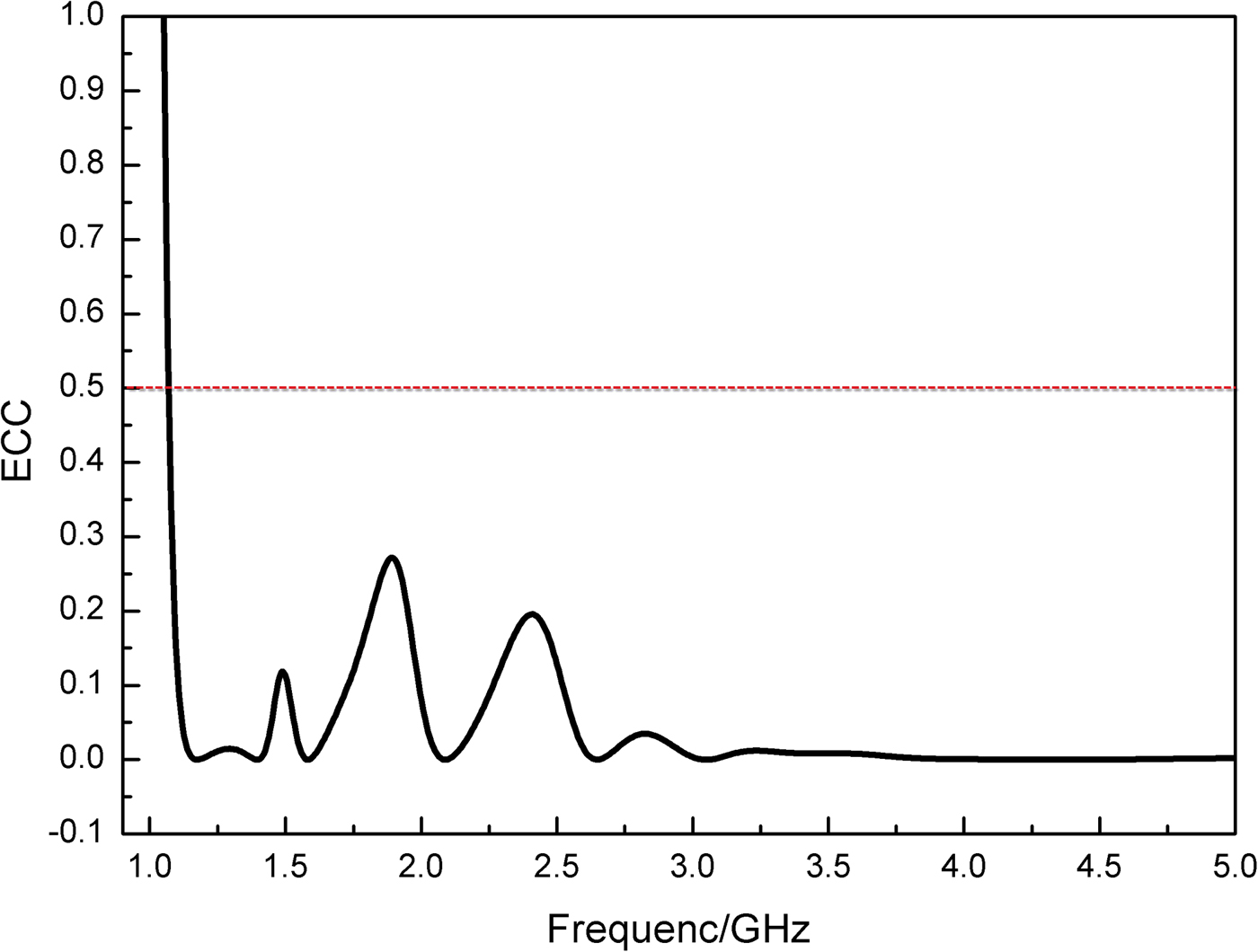
Fig. 8. ECC of decoupling antenna.
In addition, in order to distinguish our results from other existing works, geometrical dimensions, type of substrate, number of bands, decoupling mechanism, and other properties are compared in Table 3. It can be observed that the proposed MIMO antenna has more operating bands, including present 5G bands. It is more suitable for 5G smartphones.
Table 3. The comparison of proposed antenna and similar published works

Conclusion
This paper mainly studies a multi-frequency MIMO antenna system including GSM900, PCS, LTE2300, and 5G bands. The proposed MIMO antenna system consists of two symmetrical printed monopole antennas and a decoupling structure. The corresponding radiation branch is added so as to achieve the coverage of 5G frequency band. This is a highlight of this paper. Simulation and experimentation have confirmed that the performance of MIMO antenna system is desired. By adding the decoupling elements, the antenna in the LTE2300 and 5G bands at the isolation effect has been enhanced. Compared with other decoupling methods, the proposed new decoupling element not only has a simple structure but also provides a good decoupling level for closely spaced antennas. Due to the compact size, the proposed decoupling element is a suitable solution for miniaturization.
Acknowledgement
Ziyu Xu and Linyan Guo thank Xinwei Fan and the Open Lab of Rohde & Schwarz (China) Technology Co., Ltd. for the testing support. This work was supported by the National Natural Science Foundation of China (NO. 41704176, 41574131), the National Key Research and Development Program of China (NO. 2017YFF 0105704), and the Fundamental Research Funds for the Central Universities from China.
 Ziyu Xu was born in Hebei Province, China in 1994. She received her B.E degree in Measurement and Control Technology and Instrumentation from China University of Geosciences Beijing in 2017. Currently she is a master student of University of Geosciences, Beijing. Her main research interest includes the MIMO antenna, decoupling.
 Qisheng Zhang was born in Anhui province, China, in 1978. He received the M.S. degree and the Ph.D. degree, in 2012 from the Geosciences University of China, Beijing, China. He has been working in School of Geophysics and Information Technology, China University of Geosciences, Beijing, China since 2005. He is currently an associate professor in the School of Geophysics and Information Technology. His research interests include system-on-a-programmable-chip technology, measurement technology and instrument, high precision data-converters and geophysical instruments
 Linyan Guo was born in Yangcheng City, Shanxi Province, China in 1989. She received the B.E. degree in Electronic Information Science and Technology, in 2011. She also received the M.E. degree in Electromagnetic Field and Microwave Technology in 2013 and the Ph.D. degree in Radio Physics from Central China Normal University, Wuhan, China in 2016, respectively. Currently she is a lecturer of China University of Geosciences, Beijing. Her main research interest include the theory and application of metamaterials, analysis and synthesis of antennas, and Ground penetrating radar.