I. INTRODUCTION
At this moment eventually, in the fastest growing wireless communication world the spectrum shortage is a chief alarm which should be taken as a serious problem and to understand the answer for it. Currently, the electromagnetic frequency spectrum is absolutely occupied and at hand conditionally accessible spectrum for the imminent generations. In just about ten percentage of occasion, the spectrum is cleverly employed and rest of the time the electromagnetic frequency spectrum is idle. So by way of the cognitive radio, the secondary users can exercise the spectrum successfully and resourcefully without snooping with the primary users. There are different types of cognitive radios in the research. One of the types of cognitive radio is using TV frequency band and the other one is a general cognitive radio that can access any band of frequencies. Our proposed modifying Koch snowflake antenna is useful for the general cognitive radio which can access any kind of frequency spectrum.
A Koch fractal antenna has an uncomplicated arithmetical conception of a triangle. The design and investigation of the monopole and Koch fractal antenna are presented in [Reference Ismahayati, Soh, Hadibah and Vandenbosch1]. The fractal geometry concept was used in antenna design for obtaining multi-band behavior and miniaturized size. Both of these characteristics were important requirements in current antenna design trends. Antenna properties such as reflection coefficient, bandwidth, gain, and radiation pattern were analyzed and discussed. Both antennas can operate well at respective designed resonances. The third iteration of the Koch fractal antenna is proved to be advantageous over the planar monopole antenna. It has a number of resonant frequencies, larger in bandwidth and smaller in size. The Koch iteration technique was applied to a dipole antenna to get a second iteration version of Koch fractal antenna [Reference Patel, Poonkhuzhali, Thiripurasundari and Alex2]. The performance of the Koch fractal dipole antenna for 450 MHz has been primarily indicated to its fractal geometry. Koch geometry is used to reduce the overall size of the antenna. The Koch fractal antenna was designed, fabricated, and characterized on a wearable substrate and the simulation was done in CST microwave studio. The Koch iteration technique has been applied to obtain two fractal versions of a folded-slot antenna. This antenna, first and second iterations version of a Koch folded-slot antenna was fabricated on a 30 mil thick RT/Duroid substrate. The simple folded-slot antenna performs a return loss of 40 dB at the resonating frequency of 10.45 GHz and bandwidth for return loss greater than 10 dB is 1.211 GHz. The return loss of the first iteration of the Koch folded-slot antenna is 34 dB at 8.05 GHz. The return loss of the second iteration is 42 dB at 7.9 GHz [Reference Sundaram and Maddela Ramadoss3]. A Koch fractal antenna is considered as an element and an array than its electromagnetic characteristics, were examined. The method of moments is used for analyzing the antenna structure. Koch fractal monopole is used to reduce the length of the antenna, to decrease the current flowing along the body of the handset and to improve the impedance matching on the feed line to the antenna. It is used for generating circularly polarized radiation pattern and also the scattering property of the elements [Reference Zainud-Deen, Awadalla, Khamis and El shalaby4]. A high-directivity microstrip antenna based on the modified Koch snowflake geometry is presented. The third-iteration of Koch snowflake antenna geometry has been modified by introducing a fractal-shaped slot. The presence of slot is responsible for initiating and sustaining a second level of active regions. The Koch antenna exhibits an increased directivity and has improved side lobe-level behavior compared with the previously reported high-directivity Koch fractal antenna [Reference Bin Younas, Ahmed and Bin Ihsan5]. The current fashion in the communication system is to integrate several WLAN standards in small user equipment. The USB dongle for WLAN have attracted the antenna design engineers to design multi-band antennas. The antenna size is restricted to be small in size of the USB dongle. It is mainly challenged to reduce the antenna size without compromising on the performance which is related to characteristics such as wide in bandwidth, low in VSWR, and high in gain, and radiation efficiency. A novel Koch-meander fractal antenna has been proposed for the application of WLAN–USB dongle. The compact antenna is simulated in CST microwave studio. The antenna is capable of covering the whole band required for the WLAN 802.11 a/b/g standards. The effects of stacking Koch fractal antenna aperture coupled fed were investigated [Reference Jamil, Yusoff, Yahya and Zakariya6]. Hence, it is used to show that by stacking the antennas, bandwidth can be increased up to 32% at the resonance frequency of 980 MHz that are much larger than 3% bandwidth which is given by a conventional Koch fractal antenna as well as having some 14% less surface area. This antenna has an 8 dB flat gain over the bandwidth [Reference Raje, Kazemi and Hassani7]. A small size wideband which has 2–6 GHz is proposed by circularly polarized log-periodic Koch fractal antenna. The circular polarization is given by using a pair of unequal length crossed-dipoles, and the wideband property is also achieved which is based on the concept of the log-periodic dipole antenna without a matching network. Koch-shaped dipoles are used as a radiation element in the design [Reference Liu, Xu and Wu8]. It is mainly used to describe about selected simulations of the Koch fractal antennas. The difference in drifts of the voltage standing–wave ratio, S11, and other parameters of the antenna have been studied which is similar to the initiator, generator, and three fractal iterations. The multi-band and broad-band features of this antenna have been demonstrated in [Reference Malektaji and Kinsner9]. The antenna's shape and dimensions are optimized to get the area minimization which is done by applying the properties of fractal shapes in the radiating slots. The property of self-similarity in those fractals’ shapes has been successfully applied to other types of antennas as a great success. The effects of fractal miniaturization are mainly involved in the radiation pattern, the antenna efficiency and suitability of fractal shapes design for wireless communication systems [Reference Sable, Gharat, Bhosale, Khobragade and Anitha10].
This paper is organized as follows. Section II explains about the geometry of the proposed antenna and Section III describes the results and discussion.
II. GEOMETRY OF THE ANTENNA
The Koch snowflake fractal antenna can be easily constructed as shown in Fig. 1. First of all a circle was drawn with the radius of 14 mm.Within the circle, a triangle was made with the dimension of 24 × 21 mm2. After that one more triangle is added in the inverted position within the circle to form the shape like a star with six projections as shown in Fig. 1(a). Now the overall height of the two combined triangle is same as the diameter of the circle which is equal to 28 mm. At the midpoint of the triangle a rectangular slot was made to enhance the number of resonating frequencies with the dimensions of 4 × 6 mm2 and the feeding line dimensions are 1 × 6 mm2. Now the outer sides of the triangle look like a Koch curve. The Koch curve can be formed using an iterative method starting with the originator of unit line sector with n = 0. The unit line section is separated into three parts and the central part is isolated. Then the center part is swapped with two identical slices, which form an equilateral triangle with n = 1 this is the originator of the Koch curve. After that with n = 2, the center part is disconnected from each of the four sectors and all are replaced with two identical sectors as did before. This procedure is replicated to infinite number of times to construct the Koch curve [Reference Falconer11].
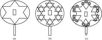
Fig. 1. Three iterations of the modified Koch snowflake.
In Fig. 1(a) on the outer sides, six identical triangles were identified which can be used as triangles to proceed to the next iteration. As we did before, joining the inverted triangles to form the star like structure, here also six small inverted identical triangles were added in the six projections of the star. Now the total triangles were increased to 18 as shown in Fig. 1(b). Then for the next iteration again 18 inverted triangles were added to form the Koch snowflake structure as in Fig. 1(c). In all the three iterations, same size of a rectangular slot and feeding lines was added as shown in Fig. 1. We made three iterations with the dimensions of side length 24 mm, and the height of 21 mm, then the inner rectangular slot with base 4 mm, and length is 6 mm. The dimensions are shown in Fig. 2. The substrate employed is FR4 with the thickness of h = 1 mm and permittivity is ε r = 4.52 with the loss tangent of tan δ = 0.02. The entire simulations were carried out by means of the ADS EMDS software.
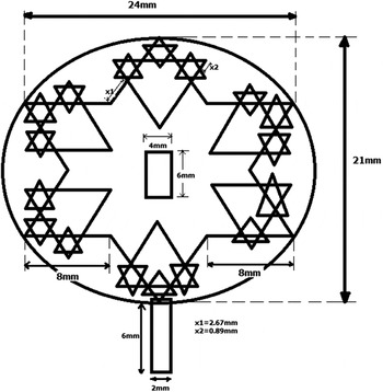
Fig. 2. Dimensions of the proposed antenna.
Each of the dimensions of the substrate is in millimeter not including conduction angle which is chosen in degrees. With the meaning of affording facts for the antenna helpfulness design, all the parameters were calculated and measured. The usefulness of the indistinguishable piece of equipment is proven by the least amount of return loss S11, which manipulates and attributes such as directivity, gain, and bandwidth.
III. RESULTS AND DISCUSSIONS
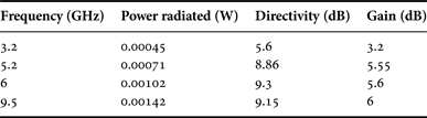
The Koch fractal antenna with the circle three iterations is simulated, and measured the result using network analyzer. This circle is responsible for impedance matching and to enhance its performance. In the first iteration, the Koch fractal antenna was constructed within the circle as shown in Fig. 1(a) and the corresponding simulated and measured results are plotted in Fig. 3(a).The return loss was obtained for the first iteration with the circle at the resonating frequency 6 GHz. Then for the second iteration the return loss was measured at 4.5, 5.8, and 6 GHz. In the third iteration, the resonating frequencies are 3.2, 5.2, 6, and 9.5 GHz. For all the iterations, the return loss is tabulated in Table 1. These frequencies cover S band (2–4 GHz), C band (4–8 GHz), and X band (8–12 GHz). For these frequencies power radiated, directivity, and gain were also measured which are tabulated in Table 2. Figure 4 (a, b and c) shows the fabricated structures using FR4 material for the iterations 1, 2 and 3 respectively. The S-band frequency is used in radio astronomy, mobile phones, and amateur radio. The C-band frequency is used in long-distance radio communications and X band for satellite communication. The radiation patterns for the three iterations of the Koch fractal antenna with circle are also plotted in Fig. 5.

Fig. 3. Layouts, simulated, and measured results of the proposed antenna.

Fig. 4. Fabricated images.

Fig. 5. Radiation patterns of the proposed antenna with ring. (a) E-field and E-theta and E-phi of 1st iteration. (b) E-field and E-theta and E-phi of 2nd iteration. (c) E-field and E-theta and E-phi of 3rd iteration.
Table 1. Return loss of the proposed antenna with ring.
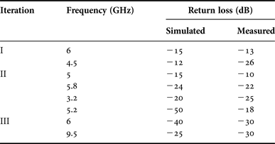
Table 2. Simulated antenna parameters for the 3rd iteration.

IV. CONCLUSION
A compact miniaturized multiband Koch snowflake fractal antenna for cognitive radio is simulated in ADS and tested using network analyzer. The size of the designed antenna is reduced to about 35% which are compared with conventional dipole antenna of the designed frequency. This multi-band antenna can be effortlessly integrated within the printed circuit boards of wireless communication devices and that can be used for wide-band spectrum sensing in cognitive radio. The proposed Koch snowflake antenna resonates at four dissimilar frequencies. Hence, the predicted antenna affords efficient command of over three operating frequency bands such as S, C, and X. The antenna gain varies from 3.2 to 6.2 dBi in excess of four resonating frequencies. This antenna has just about omnidirectional radiation pattern, and it can sense the radiation pattern in all the directions, so that it can be used for spectrum sensing in cognitive radio. The outer circle and rectangular slot what we made in the center of Koch snowflake patch antenna is responsible to increase the number of bands of frequencies.
ACKNOWLEDGEMENT
This work was supported and funded by Sathyabama University Research Center.
 S. Sivasundarapandian was born in Athipatti, Madurai, Tamilnadu, India. He received his B.E. degree in Electronics and Communication Engineering from Madurai Kamaraj University, India, and M.Tech in VLSI Design from Sathyabama University, Chennai, India. Since 2008, he has been with the Department of Electronics and Telecommunication Engineering, Sathyabama University, Chennai, India. Since 2011, he has been working toward the Ph.D. degree at the same University. His research interests include microwave devices, multi-band antennas, and RF circuits design.
 Dr. C.D. Suriyakala is an Engineering Graduate in Electronics and Communication Engineering from Manipal Institute of Technology, Manipal. She did her Masters M.S. (By Research) from Anna University, Chennai Tamilnadu and Ph.D. from Sathyabama University, Chennai. At present, she is associated with Electronics and Communication Engineering Department in Sree Narayana Gurukulam College of Engineering, Kolenchery, Kerala. She has a total experience of 22 years which include teaching as well as research. Two sponsored projects and around 50 publications in referred conferences and journals added credit in her career. Her research area is in software Agents for Communication Engineering.