


I. INTRODUCTION
Intelligent Transportation Systems (ITS) a state-of-the-art combination of transportation infrastructure and information technology will play a vital role in enabling a variety of wireless applications for safety, traffic efficiency, and infotainment [1]. The development of wireless technologies lifted researchers and manufacturers to design vehicles with navigation systems, wireless communication systems, dedicated short range communication (DSRC) systems and many more. It is important to have high-performance antenna, which will improve transmission, reception, and increase capability of the ITS. The design of an antenna with multiband operation is the development tendency for improving the utility efficiency of the limited spatial resources.
Various solutions are provided in literature to get multiband operations with single radiating element. This includes slot antennas, inverted F antennas, and printed monopole antennas. In [Reference Ijiguchi2], author introduced additional dielectric substrate with reflector to achieve vehicular antenna characteristics that makes antenna bulkier. In [Reference Wen-bo, Xiang-yang and Ji-xiang3], a dual-band slot antenna is proposed in which the antenna is affixed to a copper plate to improve impedance characteristics. In [Reference Fujimoto and Tanaka4, Reference Fujimoto and Nakanishi5], author proposed stacked antennas to resonate in multiband for vehicular applications that occupies more space in roof of the vehicle. Printed monopole antennas are currently prevalent in automotive systems because it meets the benefits of omnidirectional pattern, compact size, lower costs, ease of fabrication, and compatible with ITS requirements [Reference Koch6]. In [Reference Alsath and Kanagasabai7], two separate radiators sharing the aperture is proposed. To reduce the space planar inverted F antenna (PIFA) is integrated with “Y” shaped monopole antenna. In [Reference Lee, Hong, Lee, Park and Seong8–Reference Gamage, Engjom and Jensen10], monopole antenna is proposed to resonate at multiple frequencies. Several other multiband antennas for mobile communications can be found in literatures [Reference Kumari and Kumar11–Reference Wu and Chuang15]. The antennas discussed in literature are linear polarized.
For vehicular communications, circularly polarized antennas have better reception than linear polarized antenna when vehicles are in motion [Reference Koch6, Reference Kenney16]. It is necessary to study the multiband antenna with large ground plane, since the radiation characteristics of the antenna should not get affected with larger ground-plane structure. There should be a negligible effect on the antenna structure even, though it is placed on the larger ground plane. This characteristics is very much desired for vehicular communications. Thus, from the literature study, following conclusions can be made: (1) multiband antenna for vehicular communication needs to be omnidirectional with circular polarization; (2) effects of ground plane on radiation must be negligible; and (3) compact size.
To achieve the above-mentioned requirements, planar spiral antenna has been found to be suitable for multiband, circular polarization, and also planar spiral structure allows maximum current flow. Maximizing the current flow in the conducting element helps to minimize the antenna size. Spiral-shaped planar antennas have been developed for various mobile communication applications [Reference Yuan17–20]. Owing to the high-input impedance of the spiral antenna, it complicates the feeding system to match with 50 Ω port. Hence, it necessitates the use of balanced feed or special balun to achieve impedance matching. In this paper, a penta-band spiral antenna is proposed for vehicular communications that satisfies the above requirements and overcomes the gaps discussed in [Reference Ijiguchi2–Reference Fujimoto and Nakanishi5, Reference Alsath and Kanagasabai7–Reference Haj-Ahmed and Abedelazeez13]. It supports vehicular wireless communication services along with navigation services. To address the impedance issue of spiral antenna, a tapered feed is introduced at the outer edge of the spiral on the same plane. A smooth current flow from feed to radiating element helps to achieve better impedance matching. The proposed antenna provides circularly polarized broadside radiation pattern with improved impedance matching.
The paper is divided into four sections. Section I provides an introduction to this work, Section II explains the proposed solution with the design, and Section III explains simulated and measured results of the antenna. Finally, Section IV contains the conclusions.
II. ANTENNA DESIGN
Spiral antennas are well known for circular polarization and wider beam width. The basic form of the planar spiral antenna can be of Archimedean or equiangular spiral structure [Reference Bancroft21]. The circular polarization characteristics of Archimedean spirals are better when compared with equiangular spirals. Figure 1 shows the single-arm Archimedean spiral structure. In polar coordinates (r, θ), it can be described by the equation.
 $$\; r = a + b\theta \;, $$
where a is the initial radius and b is the spiral growth rate, controls the distance between successive turnings.

Fig. 1. Geometry of single-arm Archimedean spiral structure.
The proposed antenna design is started with fundamental microstrip patch antenna. The dimensions of the dielectric substrate is obtained using the formula stated in [Reference Bancroft21]. We considered the circumference of the inner and outer circle of the planar spiral as one fourth of the guided wavelength (λ g /4) with respect to the lower and upper frequencies to get desired multiband operation. The inner and outer radii (R 1 and R 2) of the spiral are obtained using equations (2) and (3).
 $$\; R_1 = \displaystyle{C \over {8\pi f_h}}, $$
 $$\; R_2 = \displaystyle{C \over {8\pi f_l}}. $$
Spiral growth rate and θ is fixed as 0.693 and 7π radians, respectively. The width of the spiral for N turns is calculated using,
 $$S = \displaystyle{{R_2 - R_1} \over {4N}}.$$
A) Effect of taper feed
The high-input impedance of the spiral antenna requires balanced feed or special balun to achieve impedance matching that complicates the feeding system. Impedance mismatch between the conducting element and feed line leads to narrow bandwidth. Hence, impedance matching is a significant factor for enhancing the performance of the antenna. Linear taper feed allows a smooth current flow from feed to radiating element. Thereby helps to achieve better impedance matching. Initially the antenna is fed with traditional microstrip lines without taper structure as shown in Fig. 2 and designed using Ansoft's HFSS tool. In general, width of the feed line determines the impedance. The width and length of the microstrip feed line is calculated using equations (5) and (7) with respect to middle frequency band (2.4 GHz) to achieve 50 Ω line impedance. The width and length of the feed line is further optimized to 4 and 18.1 mm respectively to achieve desired penta band. Later the impedance variation is studied by introducing taper feed and varying the taper feed slope. Taper slope calculation is shown in Fig. 2.
 $$Z = {\rm \;} \displaystyle{{120\pi} \over {\sqrt {\varepsilon _{eff}} ((w/h) + 1.393 + 0.667 \times \ln ((w/h) + 1.444))}},$$
 $$\varepsilon _{reff} = \displaystyle{{\varepsilon _{r} + 1} \over 2} + \displaystyle{{\varepsilon _{r} + 1} \over 2}\left[ {1 + 12\displaystyle{h \over w}} \right]\; ^{{ - 1/2}}\;, $$
 $$L1 = \displaystyle{{\lambda _0} \over {4\sqrt {\varepsilon _r}}} \;, $$
where ε r is the dielectric constant, w is the strip width and h is the height of the substrate, and λ 0 is the free-space wave length.
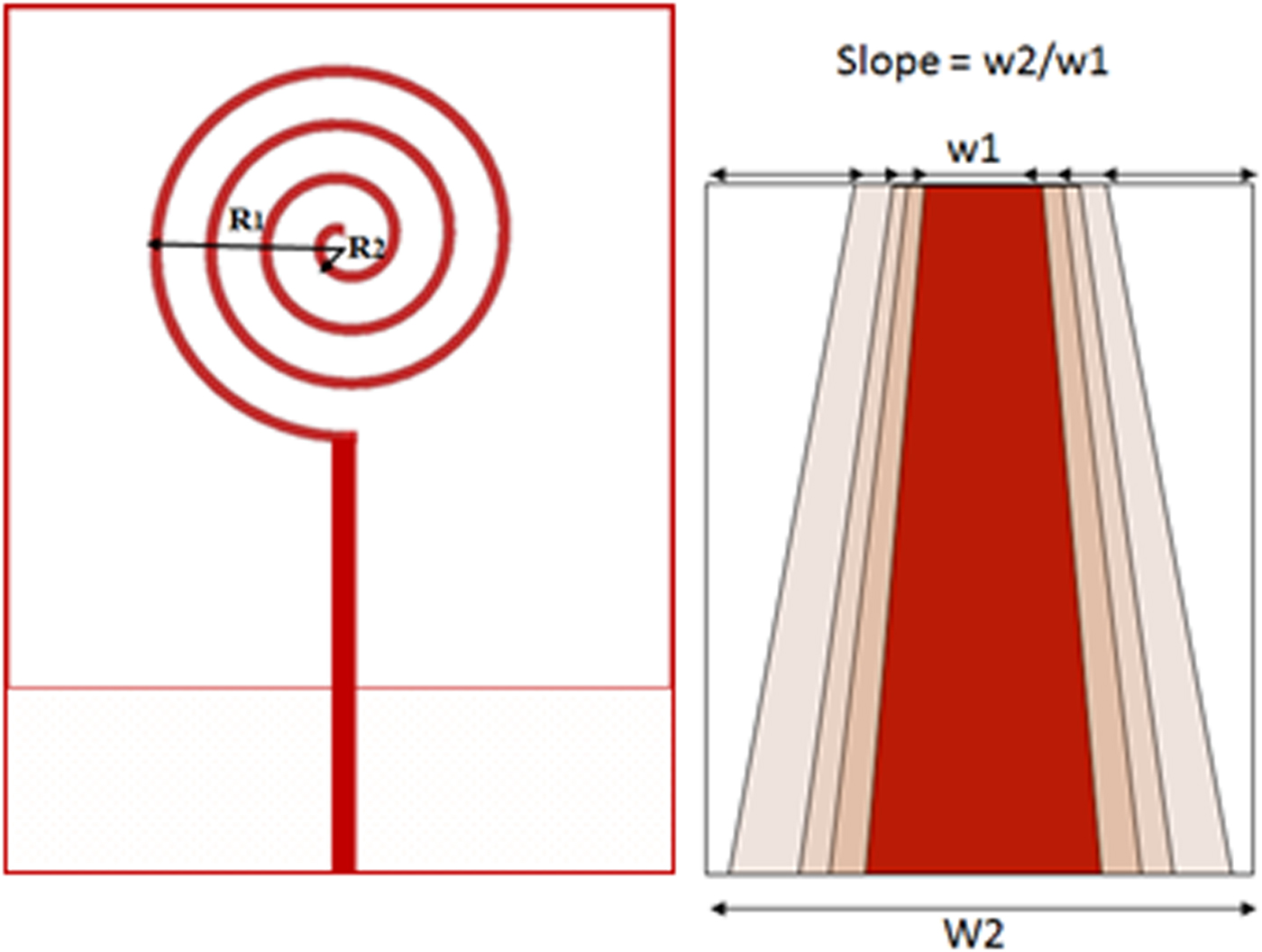
Fig. 2. Initial geometry of penta-band antenna.
By varying the taper slope, magnitude of impedance at desired frequency bands are noted. The variation in antenna impedance for various slopes is shown in Table 1. From the observation, we interpret as the slope increases the impedance of the antenna decreases to an extent and again it starts increases with further increment in slope. Though the impedance is more than 65 Ω without taper slope, it necessitates the taper structure in the feeding system. Figure 3 helps to get better clarity on effects of taper feed and it ensures the essential of taper feed. The taper slope of 1.6 gives impedance much closer to 50 Ω at all desired frequencies; hence, we fix to slope 1.6. With these W2 and slope values, fixed W1 as 2.5 mm. The final antenna dimensions are listed in Table 2.

Fig. 3. Taper effect on impedance.
Table 1. Effects of taper feed on antenna impedance.

Table 2. Dimension of the antenna.

Further, a parametric study has been conducted to investigate the effects of ground-plane size on impedance bandwidth. Figure 4 shows the return loss variation of proposed antenna with respect to ground-plane size. The study illustrate by adjusting the ground-plane length, the antenna performance can be improved. From the graph we finalized the L2 to be 4.5 mm, which helps to achieve better impedance at desired bands.

Fig. 4. Return loss characteristics of the proposed antenna with the variation in ground-plane length.
Then, the antenna is printed on 1.57 mm thickness Rogers's RT Duroid 5880 with the ε r = 2.2, and loss tangent (δ) = 0.0009. The size of the ground plane is 4.5 × 35 mm2. Simulated results are validated through Vector Network Analyzer. The geometry of the proposed antenna is shown in Fig. 5.
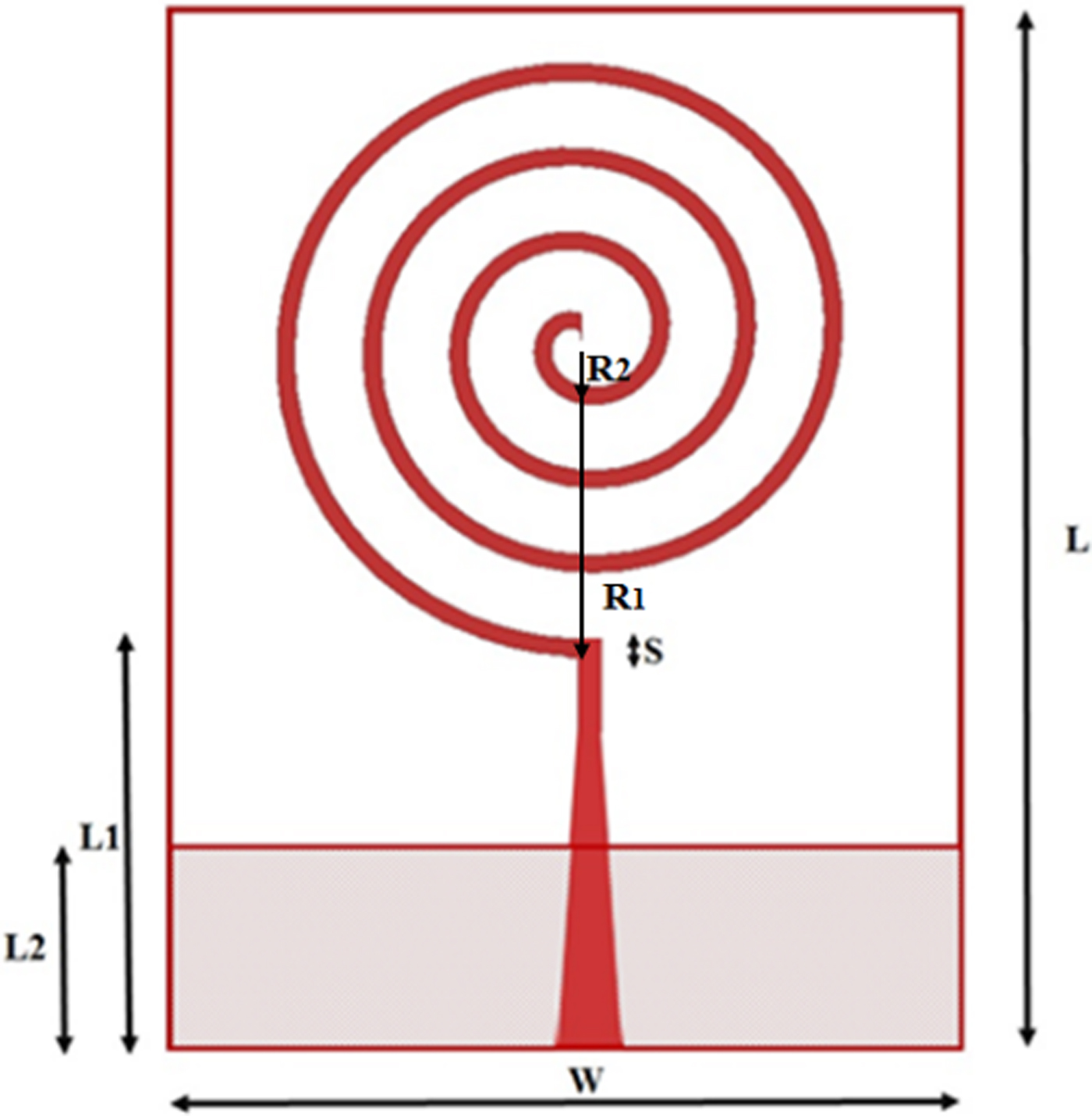
Fig. 5. Geometry of penta-band antenna with tapered feed.
III. SIMULATION AND MEASURED RESULTS
Figure 6 shows the prototype of the proposed antenna. Keysight's N9925A Vector Network Analyzer is used to validate the antenna performances. The experimental setup is shown in Fig. 7.

Fig. 6. Prototype of the proposed antenna.

Fig. 7. Experimental setup.
The comparison of simulated and experimental |S 11| parameter characteristics of the proposed antenna is shown in Fig. 8. The results show that the antenna resonates at desired penta bands. We could infer impedance bandwidth of 70 MHz (1.16–1.23 GHz), 80 MHz (1.48–1.56 GHz), 60 MHz (2.37–2.43 GHz), 120 MHz (3.25–3.37 GHz), and 810 MHz (5.37–6.18 GHz) are achieved.
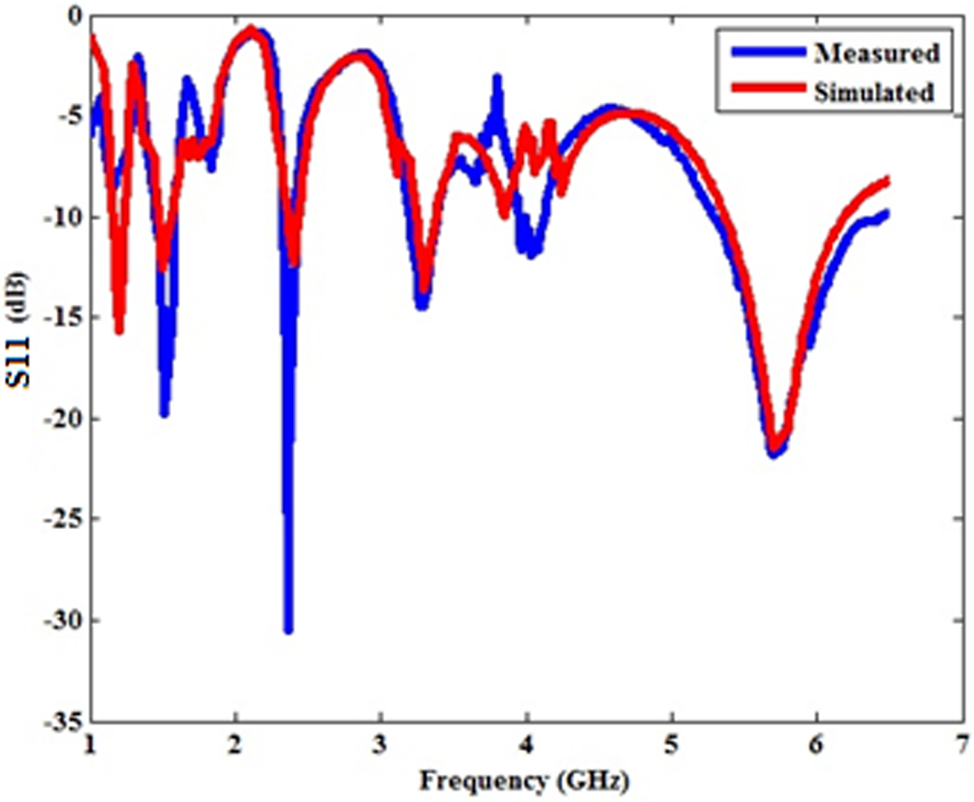
Fig. 8. Return loss characteristics of the proposed antenna.
Axial ratios are frequently mentioned for antennas whose desired polarization is circular. Axial ratio of the antenna at main lobe over the desired frequency band is shown in Fig. 9. It can be observed that, axial ratio is <3 dB at desired bands indicating that the proposed antenna is circularly polarized. Axial ratio bandwidth (ARBW) of 50, 60, 110, 170, and 370 MHz at 1.2, 1.5, 2.4, 3.3, and 5.8 GHz, respectively, are achieved.

Fig. 9. Axial ratio of the antenna at all desired frequency bands.
Figure 10 shows the measured impedance pattern. Though a small difference between simulated and measured impedance is observe, the antenna is better matched to the 50 Ω port at all bands of interest. The current distribution of the antenna at all desired frequencies shown in Fig. 11 depicts the antenna has left-hand circular polarization.

Fig. 10. The measured impedance of the penta-band antenna.

Fig. 11. Current distribution of the proposed antenna at all desired frequencies. (i) f = 1.2 GHz, (ii) f = 1.5 GHz, (iii) f = 2.4 GHz, (iv) f = 3.3 GHz, (v) f = 5.8 GHz.
SG 64 has been used for radiation measurement. It is a standalone antenna measurement with CTIA certifiable measurement facilities. Figure 12 shows the simulated and measured E and H-planes of the proposed penta-band antenna. It shows antenna has broad side radiation pattern at lower-frequency bands and quasi-broad side pattern at higher-frequency bands. At 5.8 GHz, we observed a considerable variation in maximum gain. This may be due to the quasi-broad side pattern and better return loss attained at 5.8 GHz. In addition, GPS applications require high-gain and directivity. Though the directivity of the antenna at 1.5 GHz can be improved by increasing the ground-plane length, it would affect the performance at other bands. This limits the antenna performance for GPS applications. The summary of the antenna performance are tabulated in Table 3. Good agreement between simulated and measured results is noticed. Average axial ratio bandwidth >4% is achieved over the desired bands.

Fig. 12. Comparison of simulated and measured radiation pattern of the penta-band antenna.
Table 3. Performances of the proposed antenna.

When the antenna is mounted on the body, it is essential to have negligible effect on the performance of the antenna. It is difficult to carry out the electromagnetic analysis with the whole body because of limitations of memory size. Hence, to study the effect of larger ground plane, we took the different ground-plane sizes varied from 120 × 120 to 200 × 200 mm2 in steps of 40 mm and analyzed the performance of the antenna as shown in Fig. 13. The return loss characteristics of antenna with various ground planes are shown in Fig. 14. It ensures that there is negligible effect of larger ground plane on antenna performance at all frequencies.
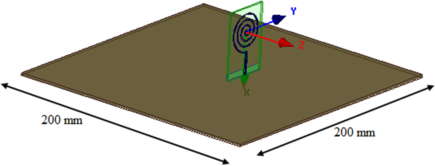
Fig. 13. The structure of the proposed antenna with large ground plane.
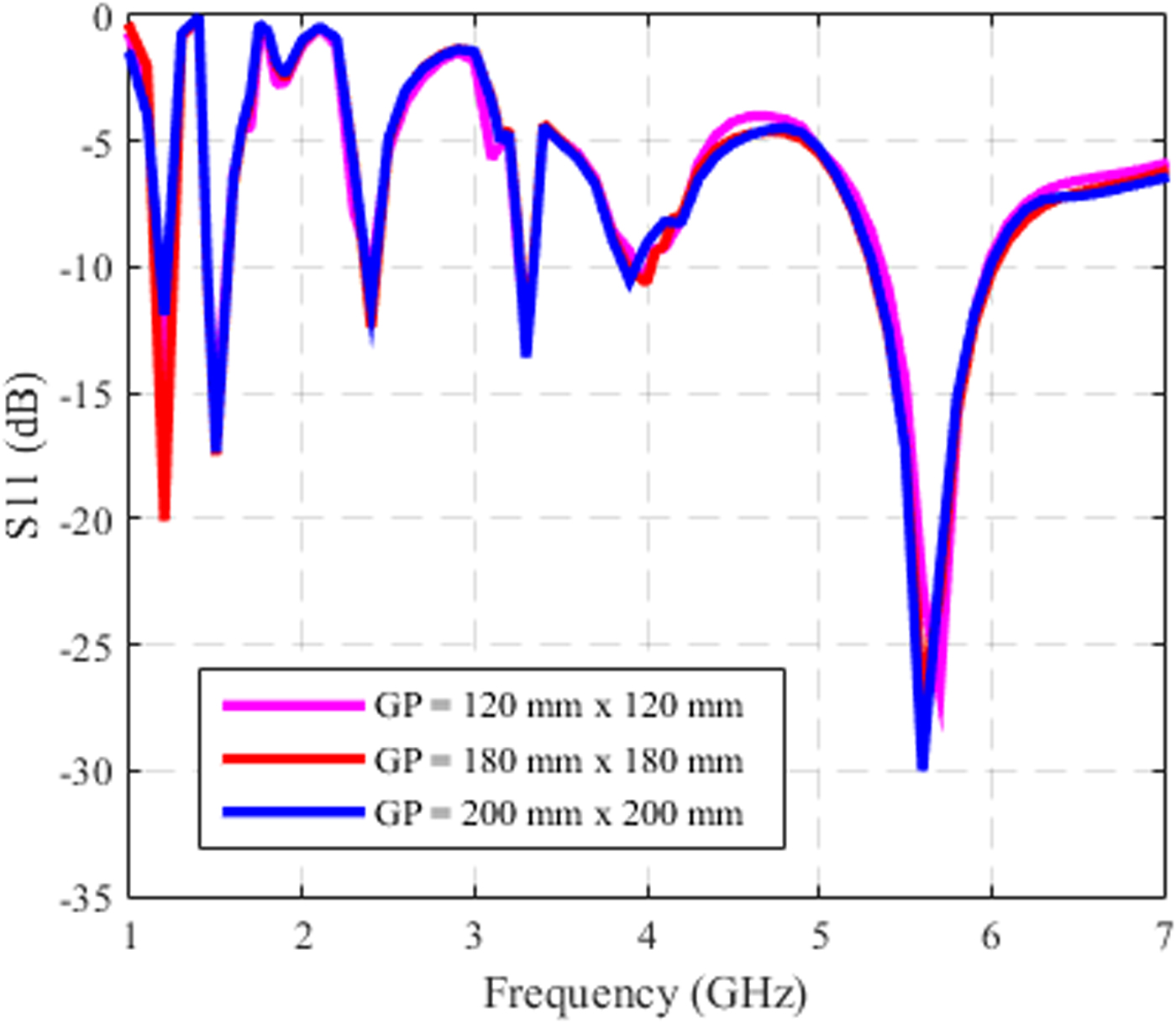
Fig. 14. Return loss characteristics of the antenna with various larger ground planes.
The effect of larger ground plane of size 200 × 200 mm2 on E and H-planes of the proposed antenna compared with measured radiation pattern is shown in Fig. 15. We infer, the presence of larger ground plane reflects the radiation and constructively adds it to the forward direction, which in-turn reflects an increase in front-to-back ratio. Table 4 lists the variation in front-to-back ratio. A small variation is observed at lower frequency bands and a considerable variation is observed at higher frequency bands, which do not impact the targeted DSRC application. Further, we continued our analysis with comparison of current work with the recent literatures. Table 5 gives the performance comparison. Current work has omnidirectional, improved ARBW and compact size with reasonable gain, which can be used as a vehicular antenna.

Fig. 15. Effects of E- and H-plane pattern at all desired frequencies placed on larger ground plane.
Table 4. Effect of larger ground plane on front-to-back ratio.

Table 5. Antenna performance comparison.

IV. CONCLUSION
The design of penta-band single-arm spiral antenna to address navigational frequencies (IRNSS & GPS), wireless frequencies (GSM/3G/Wi-Fi/WiMax), and DSRC for various vehicular wireless applications has been presented. A parametric analysis is performed to show the effect of tapered feed. Good impedance matching is achieved with tapered feed line. Thus, the antenna is better matched to the 50 Ω port. Gain of 1.07, 1.75, 1.88, 1.52, and 5.48 dB at 1.2, 1.5, 2.4, 3.3, and 5.8 GHz are obtained, respectively. Further the effect of antenna placement on the larger ground plane is studied and it is established that the deviations in return loss and radiation pattern are negligible. The prototype is fabricated and validated. There is a good agreement between simulated and measured results. The results show that the proposed antenna is suitable candidate for vehicular communications.
ACKNOWLEDGEMENT
Authors are very much grateful to Amphenol Omniconnect India Pvt Ltd, Chennai (http://www.amphenol-omni.com/) for providing access and facilities to test and measure our Antenna module performance.
 Ramya received a M. Tech. degree in Information Communications Technology from Visvesvaraya Technological University, India, in 2010 and currently pursuing her Ph.D. degree in Telecommunication Engineering, from SRM University. Her research interests include antennas, radio channel measurements & modeling, broadband wireless communications, and mobile cellular telecommunications.
 T. Rama Rao is a Professor of Telecommunication Engineering at SRM University, India, and has long-standing research experience on Radio Communications. Earlier, he worked at Aalborg University, Denmark as a Research Professor, at Universidad Carlos III de Madrid, Spain, and at the University of Sydney, Australia, as a Visiting Professor. Professor Rama Rao has been receiving significant funding from the Government of India, to develop high performance millimeter-wave antennas at 60 GHz and associated transceiver circuit for gigabit wireless applications. He is also working on inter-satellite radio link investigations at millimeter-waves with funding from the ISRO and developing wearable antennas for wearable device applications for DRDO. He is a member of IEEE, WWRF, IET, ACM, and IETE. So far, he has supervised nine Ph.D. students and authored 50+ papers in reputed journals and 90+ in various conferences. His research interests include Antennas & Its Applications, Broadband & Mobile Cellular Telecommunications.


