I. INTRODUCTION
The rapid developments in the wireless communications industry demand novel micro designs that can be used in more than one frequency band. The most widely used antenna on existing mobile telecommunication applications is probably the standard monopole antenna [Reference Chen1]. In recent years, the dual-band or multi-band antennas have received much attention for applications to multimode communication systems as these antennas are vital for integrating more than one communication standards in a single compact system to effectively promote the portability of a modern personal communication system [Reference Chiang and Tam2, Reference Anguera3]. The currently popular antenna designs suitable for the applications of wireless local area network (WLAN) and Worldwide Interoperability for Microwave Access (WiMAX) have been reported [Reference Kuo and Wong4–Reference Xiaodi9]. The traditional monopole antenna is inherently a narrow-band structure. To enhance the impedance bandwidth, the monopole with different shapes is used. As reported in [Reference Pozar and Kaufman10], a simple microstrip stub served as the impedance matching element and provided around 13% bandwidth enhancement when compared with the traditional design. To realize much wider bandwidth, additional stub could be added but the feedline becomes lengthy. In order to achieve multi-band operation, the traditional approach is to use multi-resonator elements [Reference Ge11], which generally leads to a large volume [Reference Dahele12–Reference Sappan14], or requires a large ground-plane [Reference Tan15]. In [Reference Kuo and Wong4], Kuo et al. proposed a dual-band double T-monopole antenna, which achieves a certain miniaturization factor but with a narrow bandwidth at the upper WLAN band.
In the present work, we proposed a new technique for enhancing the impedance bandwidth of a multi-frequency dual-band microstrip patch antenna. The proposed antenna employs a multistrip-based geometry fed by a cross-shaped stripline comprising one vertical and two horizontal strips and a notable ground structure named defected ground structure (DGS). Defected ground structures or slotted ground planes have been used to provide multi-band performance in handset antennas [Reference Abedin and Ali16–Reference Picher20]. The usage of DGS with double microstrip stub feedline for size reduction, bandwidth enhancement, and resonance mode increment has not been addressed for antenna's application yet. Parametric analysis and optimization of the design parameters of proposed structure was conducted using commercial software, Computer Simulation Technology Microwave Studio (CST MWS) V9. A prototype of the proposed antenna design was fabricated and tested for its performance in terms of bandwidth, gain, and radiation pattern. The details of obtained simulated and measured results are presented, analyzed, and discussed.
II. MONOPOLE ANTENNA DESIGN
The antenna configuration of the proposed resonator structure with DGS having dual-band operation covering several frequency bands is shown in Fig. 1. For designing the proposed antenna, the radiator and ground plane were etched on the opposite sides of a printed circuit board (PCB) with a dielectric constant of 4.4 and substrate thickness of 1.524 mm.

Fig. 1. Antenna configuration of the proposed antenna with defected ground structure.
A cross-shaped stripline, which comprises a vertical strip with dimensions of L 1 × W 1 and two horizontal strips with dimensions of L 2 × W 2 and L 3 × W 3, placed at distances from the feed point of d 1 and d 2, respectively, is used for feeding the radiator. Horizontal strips were used to enhance the available bandwidth for the upper band having a resonance at 5.4 GHz. The rectangular patch that is the basic radiator having the dimensions of L 4 × W 4 was protruded with three vertical arms from the patch's upper side. “Each of these three arms that make the monopole patch resemble like rotated E (Ш) have dimensions L 5 × W 5”. The solid rectangular ground plane was made defected with slots of equal dimensions, which were appropriately cut from the ground's left and right sides. These slots were introduced to improve the impedance matching condition and radiation characteristics of the proposed antenna. The overall size of ground plane was taken to be L × W and each of the slots had a vertical section of L g1 × W g1 as well as a horizontal section of L g2 × W g2. The slot was etched with a distance of d 3 from the bottom of the ground and its vertical section has a distance of W g3 from the ground side edge. A substrate of dimension 20 mm × 30 mm was used. A 50-Ω line was used to feed the patch for impedance matching.
A) Reflection coefficient and voltage standing wave ratio (VSWR)
To investigate the performance of the proposed antenna configuration, the commercially available simulation software, CST MWS V9 based on finite integration technique (FIT) was used for the required numerical analysis and to obtain the proper geometrical parameters. To simulate the antenna transient solver was chosen. During simulation hexahedral mesh cell with 20 lines per lambda was selected. The geometrical parameters were adjusted carefully by running numerous parameter sweeps and finally the optimal parameters for proposed configuration were obtained as follows: L = 30 mm, W = 20 mm, L 1 = 9 mm, W 1 = 2.8 mm, L 2 = 8 mm, W 2 = 1 mm, L 3 = 6 mm, W 3 = 1 mm, L 4 = 10 mm, W 4 = 6 mm, L 5 = 10 mm, W 5 = 2 mm, L g1 = 4 mm, W g1 = 2 mm, L g2 = 18 mm, W g2 = 8 mm, W g3 = 6 mm, d 1 = 5 mm, d 2 = 2 mm, and d 3 = 4 mm.
Figure 2 shows the simulated reflection coefficient (S 11) of proposed antenna with the optimized parameters, which confirms dual-band operation at desired bands with reasonable bandwidth. Two resonant bands at frequencies 2.385 and 5.4 GHz with bandwidths, defined for 10-dB reflection coefficient, of about 327 MHz (2.27–2.60 GHz) and 604 MHz (5.24–5.85 GHz), respectively are obtained. The multistrip-based geometry of a microstrip-fed monopole antenna with a cross-shaped stripline was responsible for the resonance at 5.4 GHz with a reflection coefficient of −44.4 dB covering the wide upper band from 5.24to 5.85 GHz and a notable DGS created a resonance at 2.385 GHz with a reflection coefficient of −20.8 dB covering the lower band from 2.27 to 2.60 GHz. During the simulation a dip in the reflection coefficient pattern at around 3.85 GHz was observed. This could be ascribed to numerical convergence problem. Apparently, the above-obtained bandwidths simultaneously cover the 2.4/5.8 GHz WLAN, 2.35 GHz International Mobile Telecommunication (IMT), 2.45 GHz BLUETOOTH, and 5.5 GHz WiMAX IEEE standards.

Fig. 2. Simulated reflection coefficient of proposed antenna showing bandwidths of 327 and 604 MHz at respective resonating frequencies of 2.385 and 5.4 GHz.
Figure 3 represents the VSWR of the proposed antenna at 2.385 and 5.4 GHz frequencies. For an ideal match the VSWR should be 1, which means no reflections. In our present case, VSWR turns out to be 1.19 and 1.012 and the impedance transformations ratio are 1:1.19 and 1:1.012 at 2.385 and 5.4 GHz, respectively, which indicate that the antenna is very well matched to a 50-Ω line allowing maximum power to be coupled through the line to antenna allowing for the best results.

Fig. 3. VSWR of the proposed antenna at 2.385 and 5.4 GHz.
B) Current distribution results
To explain more details on the excited resonant modes of the proposed antenna, the simulated current distributions at two resonant frequencies of 2.385 and 5.4 GHz are shown in Figs 4(a) and 4(b) indicating that the defected DGS was responsible for the resonance at 2.385 GHz and microstrip-fed monopole antenna was responsible for resonance at 5.4 GHz. Furthermore, a cross-shaped stripline comprising one vertical and two horizontal strips presented in Fig. 4(b) worked for enhancing the impedance bandwidth for the upper band at 5.4 GHz covering various WLAN/WiMAX standards.

Fig. 4. Surface current distributions of the proposed antenna at (a) 2.385 GHz and (b) 5.4 GHz bands.
C) Simulated reflection coefficient without DGS
Figure 5 shows the simulated reflection coefficient (S 11) of antenna without DGS. Two resonant bands at frequencies 2.385 and 5.4 GHz with bandwidths, defined for 10-dB reflection coefficient, of about 190 and 200 MHz, respectively, are obtained. These bandwidths are sufficiently less than those attained with DGS. This clearly shows the advantage of using DGS in the proposed antenna design that how it is responsible for bandwidth enhancement and resonance mode increment at the two desired bands.

Fig. 5. Simulated reflection coefficient of antenna without the DGS showing bandwidths of 190 and 200 MHz at respective resonating frequencies of 2.385 and 5.4 GHz.
III. FABRICATION AND MEASUREMENT RESULTS
The simulated antenna after detailed parametric analysis and optimization was fabricated on a dielectric substrate named Epoxy Glass-FR4 (ε r = 4.4, tanδ = 0.0024, h = 1.524 mm) and was studied experimentally. Available photolithography method with wet-etching facility was adopted for fabrication of the prototype antenna and its photograph is shown in Fig. 6. After fabrication, the reflection coefficient of the antenna was tested on Agilent E5071C vector network analyzer and the radiation performance was measured in the Anechoic Chamber at Millimeter Wave Laboratory, I.I.T-Roorkee, India. The measured reflection coefficient against frequency plot for this dual-band proposed antenna design covering multiple frequency bands is presented in Fig. 7.

Fig. 6. Photograph of the proposed antenna.

Fig. 7. Measured reflection coefficient of the proposed antenna.
Measured reflection coefficient of proposed MSA indicates that two resonant modes at frequencies of 2.385 and 5.4 GHz were obtained with reflection coefficient as −20.4 and −43.2 dB, respectively. The measured impedance bandwidths of the two distinct operating bands with 10 dB reflection coefficient were about 240 MHz (2.3–2.54 GHz) and 590 MHz (5.26–5.85 GHz). They are wide enough to cover the required bandwidths of 2300–2400 MHz for IMT band, 2400–2484 MHz for WLAN/Industrial, Scientific and Medical band (ISM), 2400–2500 MHz for BLUETOOTH band, 2484–2491 MHz for Globalstar satellite phone uplink, 5250–5850 MHz for WiMAX band and 5725–5825 MHz for WLAN band/Intelligent Transport Systems (ITS) working in the 5.8 GHz frequency band. The multistrip monopole antenna fed by a cross-shaped stripline was responsible for the resonance at 5.4 GHz and a notable DGS created a resonance at 2.385 GHz. Two slots that were appropriately distracted from the ground's left and right sides improved the impedance matching condition and radiation characteristics of the proposed antenna. A quite good agreement was seen between the simulated and measured results for the proposed antenna. A little shift in both the resonating bands was observed during measurement, which could be attributed to mismatching between the connector and the antenna feeder, fabrication errors, interference, and noise.
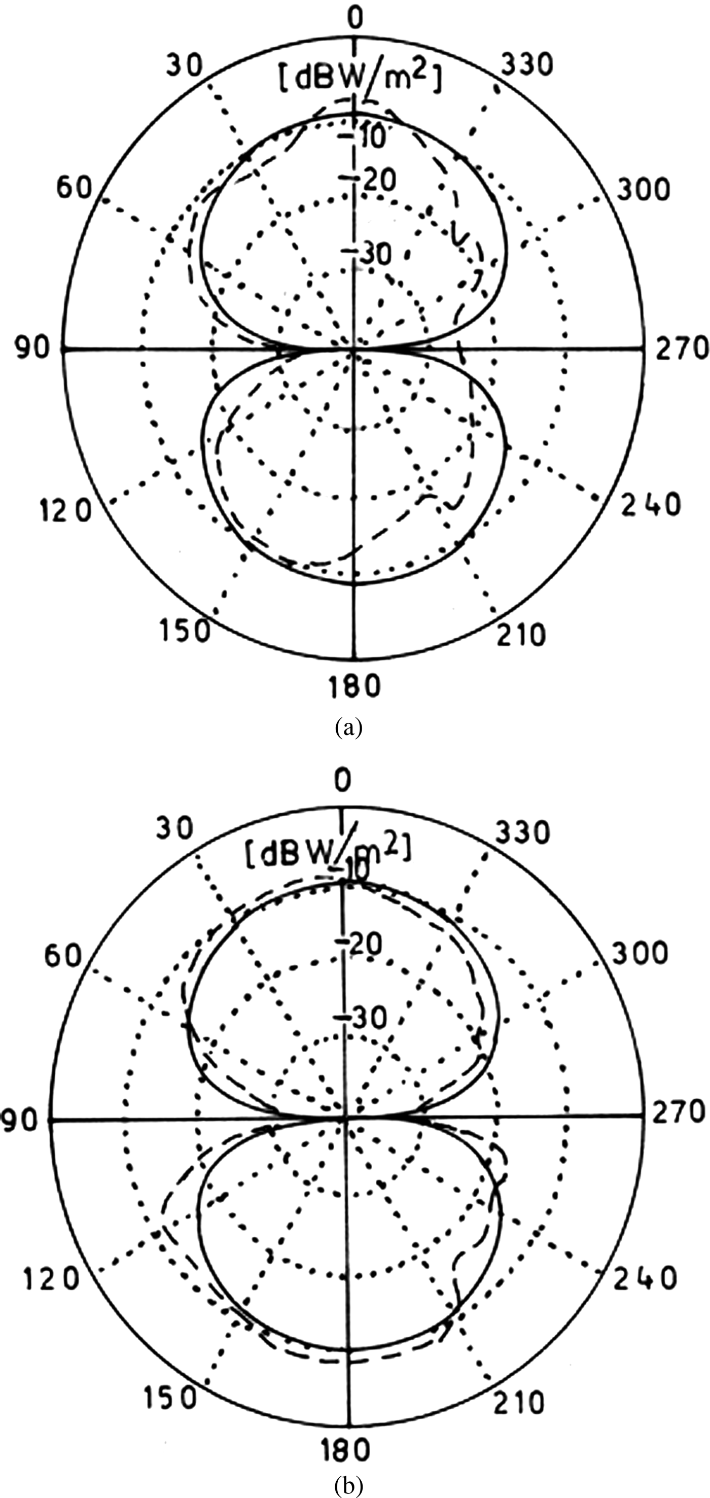
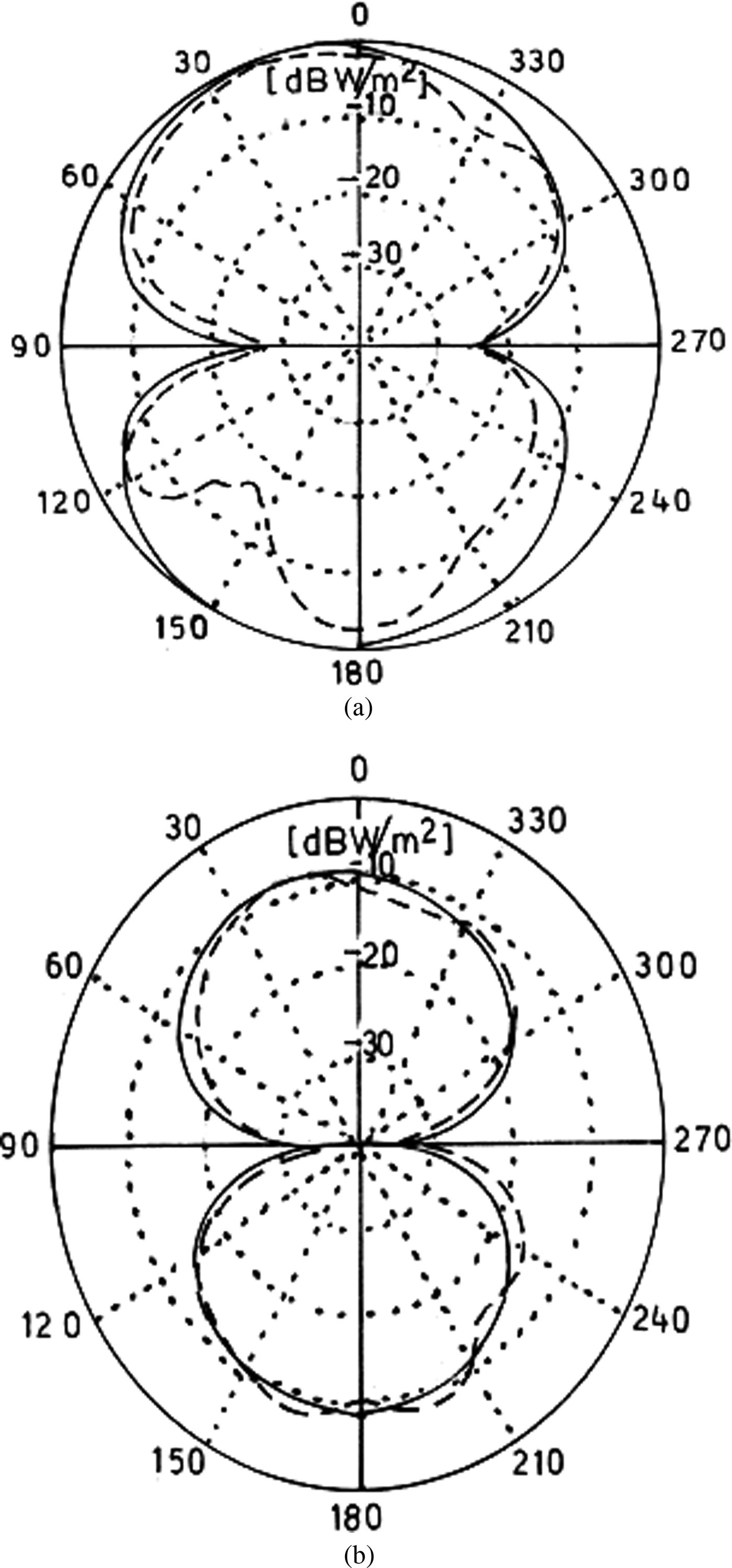
Figures 8 and 9 depict the simulated and measured far-field radiation patterns of the proposed antenna in both the E-plane and H-plane at the operating frequency bands of 2.385 and 5.4 GHz. Because of the symmetry in structure, rather symmetrical and very monopole-like radiation patterns are seen in both the planes as depicted in the plots. The simulated and measured radiation patterns in Figures 8 and 9 were normalized for setting the maxima 0 dB. Reasonable good agreement was found between the simulated and measured values of radiation patterns in two distinct operating frequency bands, which validate the proposed design. Some slight differences between the simulated and measured field patterns may be attributed to alignment error and possible presence of interference and noise.

Fig. 8. Simulated (solid) and measured (dash) (a) E-plane radiation pattern and (b) H-plane radiation pattern at 2.385 GHz.

Fig. 9. Simulated (solid) and measured (dash) (a) E-plane radiation pattern and (b) H-plane radiation pattern at 5.4 GHz.
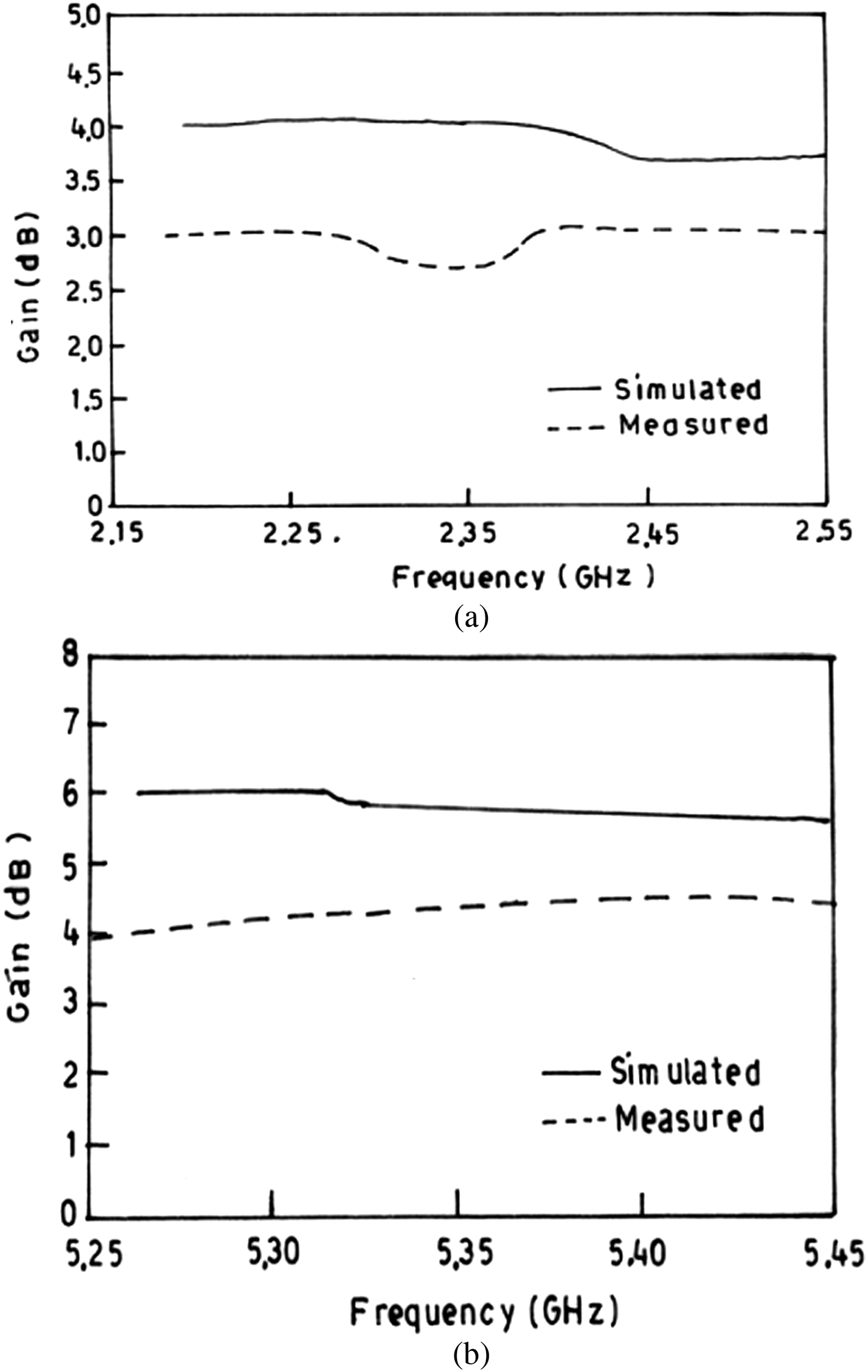
The simulated and measured gain curves for two operating bands at 2.385 and 5.4 GHz are presented in Fig. 10. The transmitter antenna was given 15 dBm power from the RF power generator, and the distance between the transmitter and the receiver was kept at 1.5 m. Gain was calculated using the substitution method with the help of the standard calibrated horn antenna (reference antenna) working in the range of 0.9–8 GHz. About 1–2 dB of difference in the simulated and measured gains was observed, which could be attributed to fabrication and measurement errors.

Fig. 10. Simulated (solid) and measured (dash) gains of the proposed antenna at (a) 2.385 GHz and (b) 5.4 GHz.
IV. CONCLUSION
In this paper, dual-band operation of a multistrip monopole antenna was presented, which could be suitable to cover 2300–2400 MHz for IMT band, 2400–2484 MHz for WLAN/ISM, 2400–2500 MHz for BLUETOOTH band, 2484–2491 MHz for Globalstar satellite phone uplink, 5250–5850 MHz for WiMAX band, and 5725–5825 MHz for WLAN band/ITS working in the 5.8 GHz frequency band. The microstrip line feeding method used in our design enabled direct feeding of the structure without using complicated impedance transformer or microstrip taper. The monopole antenna fed by a cross-shaped stripline comprising one vertical and two horizontal strips was responsible for the resonance at 5.4 GHz and a notable DGS created a resonance at 2.385 GHz. Obviously, both the multistrip-based geometry of patch and DGS play a vital role in generating these two strong resonating frequency bands. The fabricated prototype upon measurement shows reasonable impedance bandwidths of around 200 MHz (2.3–2.54 GHz) and 590 MHz (5.26–5.85 GHz) in two operating bands, which actually exceed the requirements of any WLAN/WiMAX application. Thus, in the present study, it was observed that using such a new technique of incorporating a multistrip patch and DGS in antenna design, two distinct operating bands with an impedance bandwidth of 10% from 2.3 to 2.54 GHz and a bandwidth of 11% from 5.26 to 5.85 GHz can be achieved. Also, appreciable gain and radiation characteristics have been observed over the entire operating range. Hence, the proposed design can be easily integrated to microwave circuits and compatible with monolithic microwave integrated circuit technology for practical applications.
ACKNOWLEDGEMENT
The authors are grateful to Mr. J. Malik, Research Scholar, I.I.T Roorkee, India, for his support.


