Introduction
Multiband planar antennas are an integral part of many wireless communication systems. Microstrip antennas are widely used due to their low profile and ease of fabrication. In the past, different techniques have been reported to realize dual band microstrip patch antennas, which usually employ stacked patch configuration [Reference Long and Walton1], or reactive loading in the form of slots [Reference Maci, Gentili and Avitabile2–Reference Lee, Yang and Kishk4].
Metamaterials due to their unique properties provide new ways of antenna design [Reference Lai, Itoh and Caloz5–Reference Dong and Itoh7]. In particular, composite right/left-handed transmission line (CRLH TL) metamaterials are attractive due to their ease of fabrication. They can be used to achieve antenna size miniaturization using the zeroth order resonance (ZOR) mode and multifrequency operation [Reference Dong and Itoh7–Reference Yan and Vandenbosch13]. A dual band CRLH TL antenna using ±1st order resonance is reported in [Reference Caloz and Itoh8]. However, only fixed large frequency ratio is possible using this method. A linearly polarized multiband patch antenna, partially filled with mushroom type CRLH structure is presented in [Reference Herraiz-Martinez, Gonzalez-Posadas, Garcia-Munoz and Segovia-Vargas9], wherein it is shown that two antenna configurations are possible: a dual mode tri-band antenna having broadside pattern at ±1st order resonances and omnidirectional (monopolar) pattern at ZOR mode; or a dual band antenna having broadside pattern employing ±1st order resonances. Although, arbitrary frequency ratio can be obtained using this technique but it suffers from low radiation efficiency at −1 resonance. A dual band circularly polarized antenna loaded with mushroom type CRLH structure is reported in [Reference Dong, Toyao and Itoh10]. Circular polarization is achieved by exciting two orthogonal −1 resonances with 90° phase difference. Recently, a dual band pattern diversity patch antenna using CRLH TL is presented in [Reference Yan and Vandenbosch11]. It employs an annular ring with circular patch antenna placed at the center, both loaded with CRLH TL. The annular ring provides broadside pattern using ±1st order modes while circular patch provides a monopolar pattern. Although, the reported antenna has good radiation efficiency, broadside radiation patterns are not identical at upper and lower frequency bands. Moreover, fabrication complexity increases due to the multilayer structure.
In general, most of the metamaterial loaded antennas reported in the literature are based on the mushroom type CRLH structure wherein dual band operation with broadside pattern is achieved using symmetric ±1 modes. ZOR mode is primarily used for antenna size reduction or to achieve an omnidirectional pattern in the horizontal plane [Reference Herraiz-Martinez, Gonzalez-Posadas, Garcia-Munoz and Segovia-Vargas9, Reference Lai, Leong and Itoh12, Reference Yan and Vandenbosch13]. However, as per our knowledge, no work has been reported where ZOR mode is used for dual band frequency reconfigurable applications, with broadside radiation pattern and arbitrary non-integer frequency ratio.
In this paper, we propose a novel dual band CRLH TL coupled patch antenna. In the proposed configuration, a CRLH TL unit cell is gap coupled with the radiating edge of the patch. The dual band operation is achieved by resonant coupling the ZOR mode of CRLH TL and TM 10 mode of the patch antenna. The proposed antenna is distinct in the sense that dual resonance is not obtained using symmetric ±1 modes but ZOR mode and TM 10 mode coupling. Good radiation efficiency and almost identical broadside radiation patterns are achieved at both resonance frequencies. Another advantage of the proposed configuration is that it can be employed to design frequency reconfigurable dual band patch antenna by changing the left-hand inductance of proximity coupled CRLH TL unit cell. In addition, the proposed antenna is simple to fabricate and suitable for single layer dual band array applications.
Dual band CRLH TL coupled patch antenna
Antenna configuration and working principle
The proposed antenna geometry is shown in Fig. 1. It consists of a rectangular patch antenna, which is gap coupled to a symmetrical CRLH TL unit cell along the radiating edge of the patch. The CRLH TL cell is composed of an interdigital capacitor and a meander line inductor. A virtual ground capacitor is employed to achieve via less design. The antenna is designed using Rogers RT/Duroid 5880 substrate having ε r = 2.2 and thickness h = 1.58 mm. A single coaxial probe is used to feed the patch antenna.
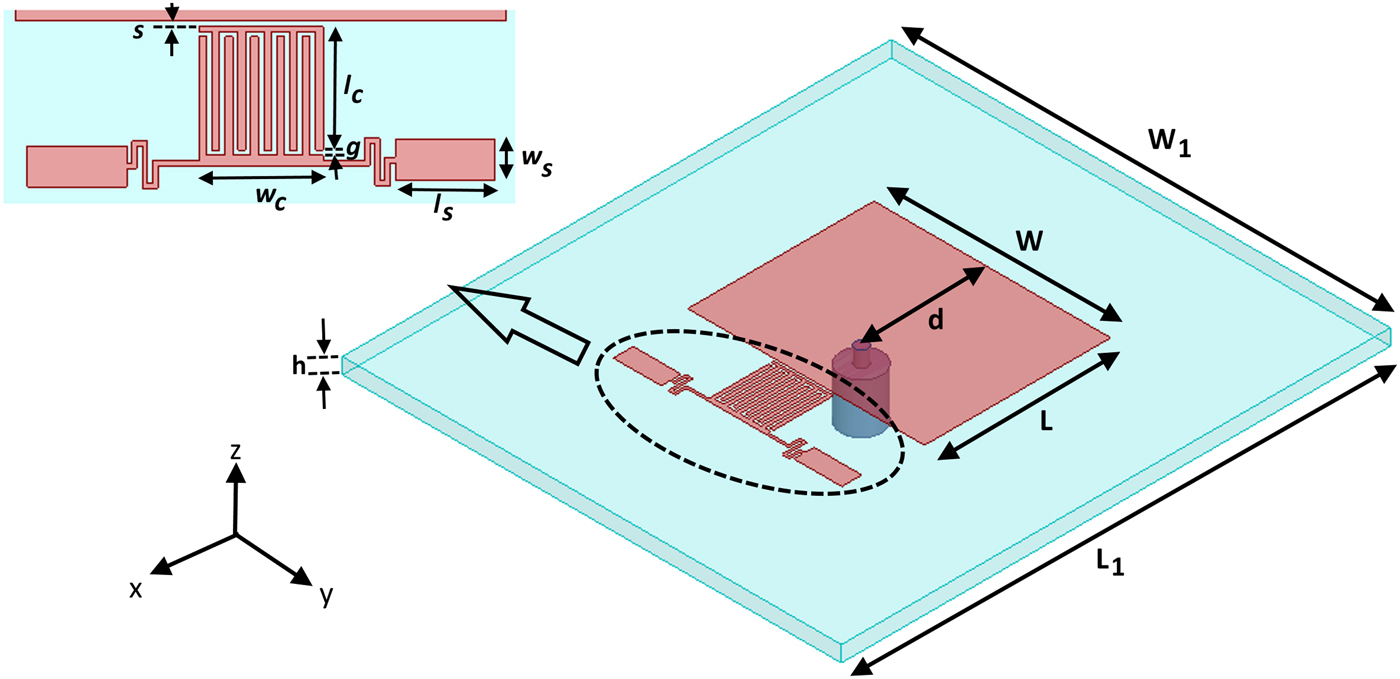
Fig. 1. Geometry of the proposed antenna (W = 23.72, L = 18.65, W 1 = 50, L 1 = 55, d = 13.12, s = 0.25, l c = 5.75, w c = 6, l s = 4.8, w s = 2, g = 0.25, all dimensions in mm).
An approximate equivalent circuit model of the proposed CRLH TL coupled patch antenna is shown in Fig. 2. A T-type equivalent circuit is used to represent the symmetric CRLH unit cell [Reference Dong and Itoh7] and a parallel RLC resonator with series probe inductance L s is used to model the patch antenna. The patch antenna is capacitive coupled to the CRLH TL unit cell by a capacitance C. The equivalent circuit parameters of CRLH TL unit cell are extracted using an off-resonance technique given in [Reference Haupt and Lanagan14].
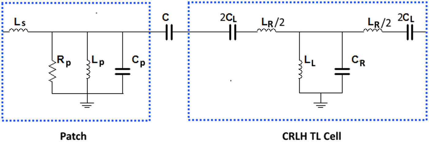
Fig. 2. Equivalent circuit model of the proposed antenna (L S = 0.84 nH, R P = 180 Ω, L P = 0.29 nH, C P = 3.56 pF, C = 0.7 pF, C L = 0.62 pF, L R = 1.63 nH, L L = 0.23 nH, C R = 4.32 pF).
One of the advantages of the proposed antenna is that the CRLH TL unit cell and patch antenna can be designed separately thus providing design simplicity. The design of the antenna can be carried out in three steps: (a) patch antenna design, (b) CRLH TL unit cell design, and (c) coupling design. First, a coaxial fed rectangular patch antenna is designed operating in the fundamental TM10 at the resonance frequency of 5 GHz. Next, a symmetrical CRLH TL unit cell is designed operating in ZOR mode. The phase constant β for CRLH TL unit cell is given by [Reference Lai, Itoh and Caloz5].
 $$\beta = z(\omega )\sqrt {\omega ^2L_RC_R + \displaystyle{1 \over {\omega ^2L_LC_L}} - \left( {\displaystyle{{L_R} \over {L_L}} + \displaystyle{{C_R} \over {C_L}}} \right)} $$
where
 $${\kern 1pt} {\kern 1pt} z(\omega ) = \left\{ \matrix{ - 1{\kern 1pt} {\kern 1pt} {\kern 1pt} {\kern 1pt} {\kern 1pt} {\kern 1pt} {\kern 1pt} {\kern 1pt} {\kern 1pt} {\kern 1pt} if\,{\kern 1pt} {\kern 1pt} {\kern 1pt} {\kern 1pt} {\kern 1pt} {\kern 1pt} {\kern 1pt} {\kern 1pt} {\kern 1pt} \omega \lt \omega_{\Gamma 1} = \min \left( {\displaystyle{1 \over {\sqrt {L_RC_L}}}, \displaystyle{1 \over {\sqrt {L_LC_R}}}} \right) \hfill \cr + 1{\kern 1pt} {\kern 1pt} {\kern 1pt} {\kern 1pt} {\kern 1pt} {\kern 1pt} {\kern 1pt} {\kern 1pt} {\kern 1pt} {\kern 1pt} if\,{\kern 1pt} {\kern 1pt} {\kern 1pt} {\kern 1pt} {\kern 1pt} {\kern 1pt} {\kern 1pt} {\kern 1pt} {\kern 1pt} \omega \gt \omega_{\Gamma 2} = \max \left( {\displaystyle{1 \over {\sqrt {L_RC_L}}}, \displaystyle{1 \over {\sqrt {L_LC_R}}}} \right) \hfill} \right..$$
Figure 3 shows the dispersion diagram of the CRLH TL. Two separate regions i.e. left-hand (LH) region and right-hand (RH) region can be observed. The ZOR mode is obtained at 5.06 GHz which corresponds to β = 0 in the dispersion diagram. Finally, the dual mode behavior is realized by coupling the TM10 mode patch and ZOR mode CRLH TL unit cell. The spacing between the patch and CRLH TL unit cell affect the coupling. It will be shown in the section Parametric Study that this can be used to vary the frequency ratio of the proposed dual band patch antenna. In fact, it is possible to initially design the patch antenna and CRLH TL unit cell operating at the same resonance frequency and to control the frequency ratio later by changing the spacing between them. Since the resonance frequencies of coupled resonators (synchronously or asynchronously tuned) are different than the uncoupled single resonators. As an example, a frequency ratio of f 2/f 1 = 1.08 is demonstrated in the proposed design which corresponds to s = 0.25 mm.

Fig. 3. Dispersion diagram of CRLH TL unit cell.
Further insight into the working of the proposed CRLH TL coupled dual band patch antenna can be gained by examining the electric field (E-field) distribution. Figure 4 shows the E-field distributions of the antenna at lower and upper resonance frequencies. It can be seen that the coupling mechanism at both resonance frequencies is different. At lower resonance frequency, the E-field of TM10 mode and ZOR mode is out of phase. By contrast, the E-field of both modes is in phase at the upper resonance frequency. This behavior is similar to odd and even mode coupling in coupled resonators [Reference Costantine, Tawk, Barbin and Christodoulou15].
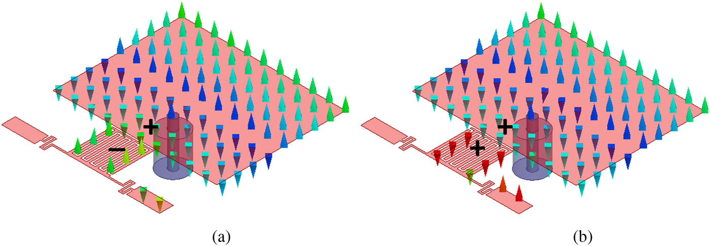
Fig. 4. Electric field distributions of the proposed dual band patch antenna (a) lower resonance frequency f 1 and (b) upper resonance frequency f 2.
Parametric study
A parametric study was conducted to investigate the effects of different parameters on the performance of the proposed CRLH TL coupled patch antenna. All the simulations were performed using full-wave EM simulator HFSS by changing only one parameter at a time. Figure 5 shows the simulated reflection coefficient (S 11) of the proposed antenna for different values of the coupling gap s. It can be observed that by changing the value of s, the lower resonance frequency f 1 is affected more as compared with the upper resonance frequency f 2. Thus, it can be used to control the frequency ratio f 2/f 1. The smaller coupling gap results in a larger frequency ratio. The effect of interdigital capacitor length l c on the S 11 is shown in Fig. 6. By increasing l c, upper and lower resonance frequencies decrease and both peaks shift downward. Thus, frequency ratio is not affected by changing interdigital capacitor length l c but it can be used to set the desired dual band resonance frequencies. Figure 7 shows the effect of patch length L on the S 11. Its behavior is similar to interdigital capacitor length l c. As the patch length increases from L = 18.3 to L = 19 mm, both resonance peaks move down towards a lower resonance frequency.
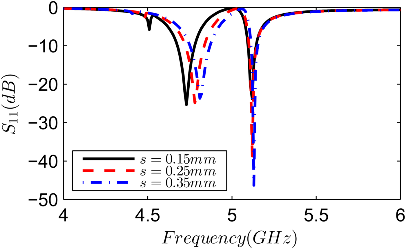
Fig. 5. Effect of coupling gap s on the S 11 of the proposed antenna.
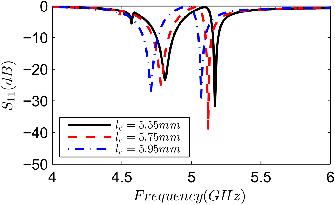
Fig. 6. Effect of interdigital capacitor length l c on the S 11 of the proposed antenna.
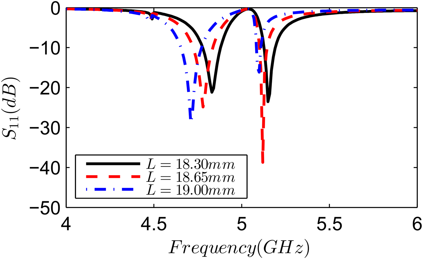
Fig. 7. Effect of patch length L on S 11 of the proposed antenna.
Frequency Reconfigurable Patch Antenna
Reconfigurable antennas are crucial to cater to the ever increasing demand of high data rates in modern wireless communication applications [Reference Chaudhry, Arif, Ahmed, Chaudhary and Ihsan16, Reference Pozar17]. The proposed CRLH TL coupled patch antenna can achieve frequency reconfigurability by changing the CRLH TL unit cell. This can be realized practically by switching on and off, one of the two meander line arm of symmetric CRLH TL unit cell. This essentially reduces the left-hand inductance by half and affects the resonance frequencies of dual band structure. Figure 8 shows the simulated S 11 plot of the proposed antenna as a function of frequency for two positions of switch S. Switching is implemented by simulating the switch S as an open and short circuit, representing the off and on state respectively. It can be observed from Fig. 8 that by switching off one meander line arm of CRLH unit cell, first resonance frequency peak moves up from 4.75 to 4.95 GHz, whereas second resonance frequency peak move down from 5.12 to 4.41 GHz. Thus beside change in resonance frequencies, frequency ratio is also affected by the switch position. The frequency ratio f 2/f 1 before and after switching is 1.08 and 1.12, respectively. Although not shown, switching off both the meander line arms (using two switches) will result in a single band patch antenna.
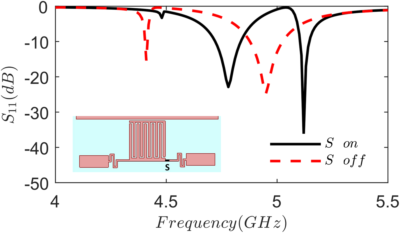
Fig. 8. S 11 of frequency reconfigurable dual band patch antenna.
Results and discussions
A prototype of the proposed CRLH TL coupled patch antenna was fabricated. LPKF PCB milling machine was used to fabricate the antenna. A snapshot of the fabricated antenna is shown in Fig. 9. The simulated and the measured S 11 are shown in Fig. 10. Agilent PNA network analyzer E8362B was used to measure the S 11. Measurement result (Fig. 10) shows a dual impedance bandwidth (S 11 ≤ −10 dB) of 100 MHz (from 4.78 to 4.88 GHz) and 50 MHz (from 5.2 to 5.25 GHz). Simulated and measured results are in reasonable agreement. A slight shift in the measured S 11 may be attributed to the fabrication tolerances.
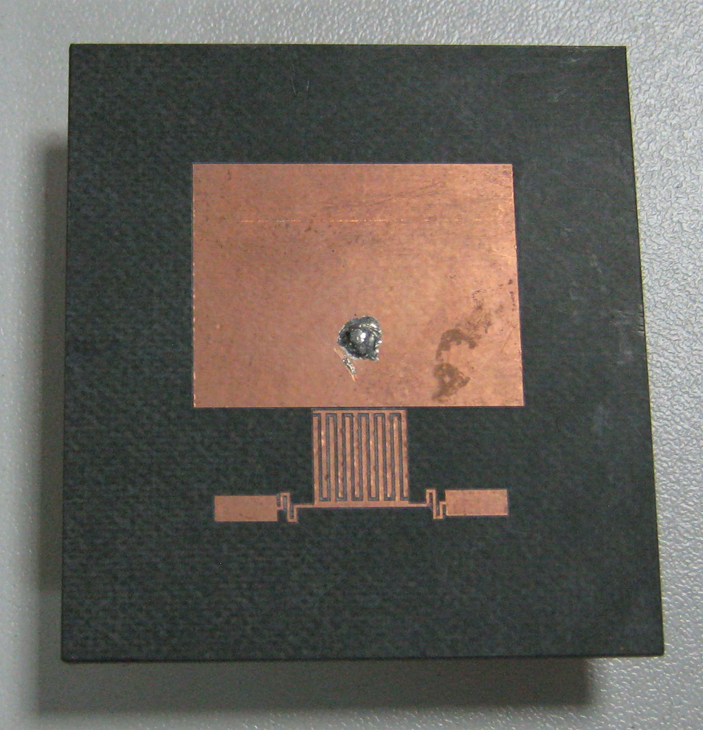
Fig. 9. Fabricated dual band CRLH TL coupled patch antenna.
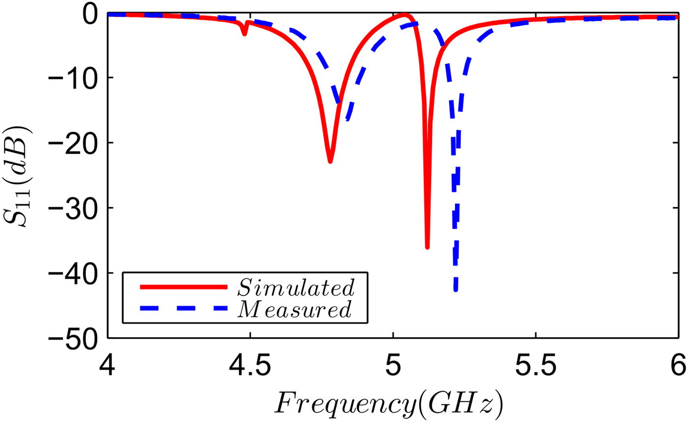
Fig. 10. Simulated and measured S 11 of dual band CRLH TL coupled patch antenna.
Simulated and measured E- and H-planes normalized radiation patterns of the proposed antenna at resonance frequencies of 4.84 and 5.22 GHz are shown in Figs 11 and 12, respectively. Antenna shows broadside almost identical radiation patterns at both resonance frequencies. The measured cross polarization levels are less than −16 dB at both frequencies. The measured antenna gain is 7.4 and 5.8 dBi at lower and upper resonance frequencies.
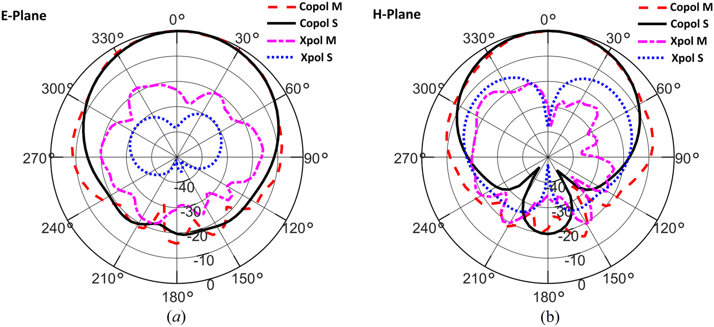
Fig. 11. Simulated and measured radiation patterns of dual band CRLH TL coupled patch antenna at f 1 = 4.84 GHz (a) E-plane and (b) H-plane.
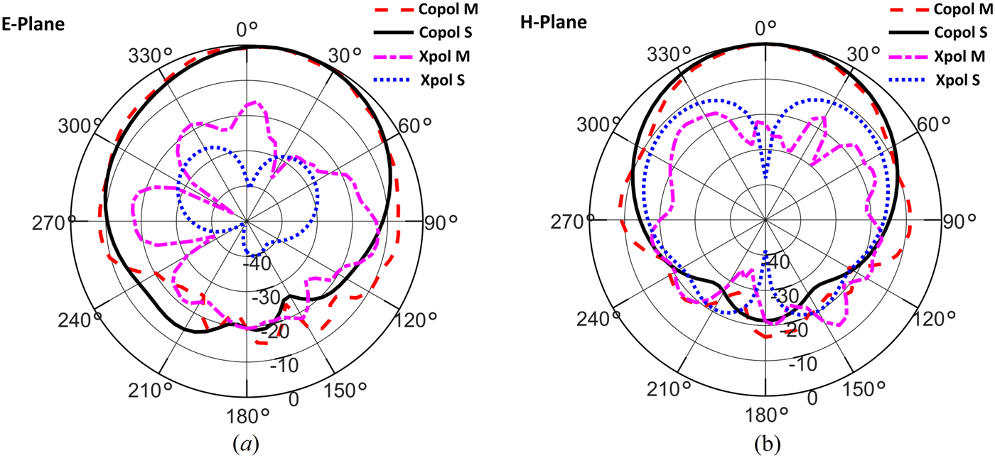
Fig. 12. Simulated and measured radiation patterns of dual band CRLH TL coupled patch antenna at f 2 = 5.22 GHz (a) E-plane and (b) H-plane.
Table 1 shows a comparison of different CRLH TL based dual band patch antennas found in the literature. In contrast to previously reported works which use symmetric ±1 modes for dual band operation, the proposed antenna uses ZOR and TM 10 modes coupling to achieve dual band behavior. Another advantage of the proposed configuration is that it allows frequency reconfigurability. Moreover, the proposed antenna has good radiation efficiency and similar gain at both upper and lower resonance frequencies bands. In addition, due to single layer structure and via less design, it provides ease of fabrication.
Table 1. Comparison of different CRLH TL-based dual band antennas.

Dual band CRLH TL coupled patch array
The proposed antenna can be used to design dual band high gain patch arrays. As an example, a 2 × 2 corporate fed dual band CRLH TL coupled patch array is demonstrated. The array geometry is shown in Fig. 13. Since microstrip feeding is more suitable for a patch array design, an inset fed dual band CRLH TL coupled patch antenna was optimized with an input impedance of 100 Ω and used as an array element. A corporate feed network was used to uniformly excite the individual elements. The interelement spacing between the center of patches is 42 mm, which is equal to 0.67 λ 0 at lower frequency of 4.82 GHz and 0.72 λ 0 at upper frequency of 5.15 GHz, respectively. The array is fed by means of a coaxial probe at the center as illustrated in Fig. 13.
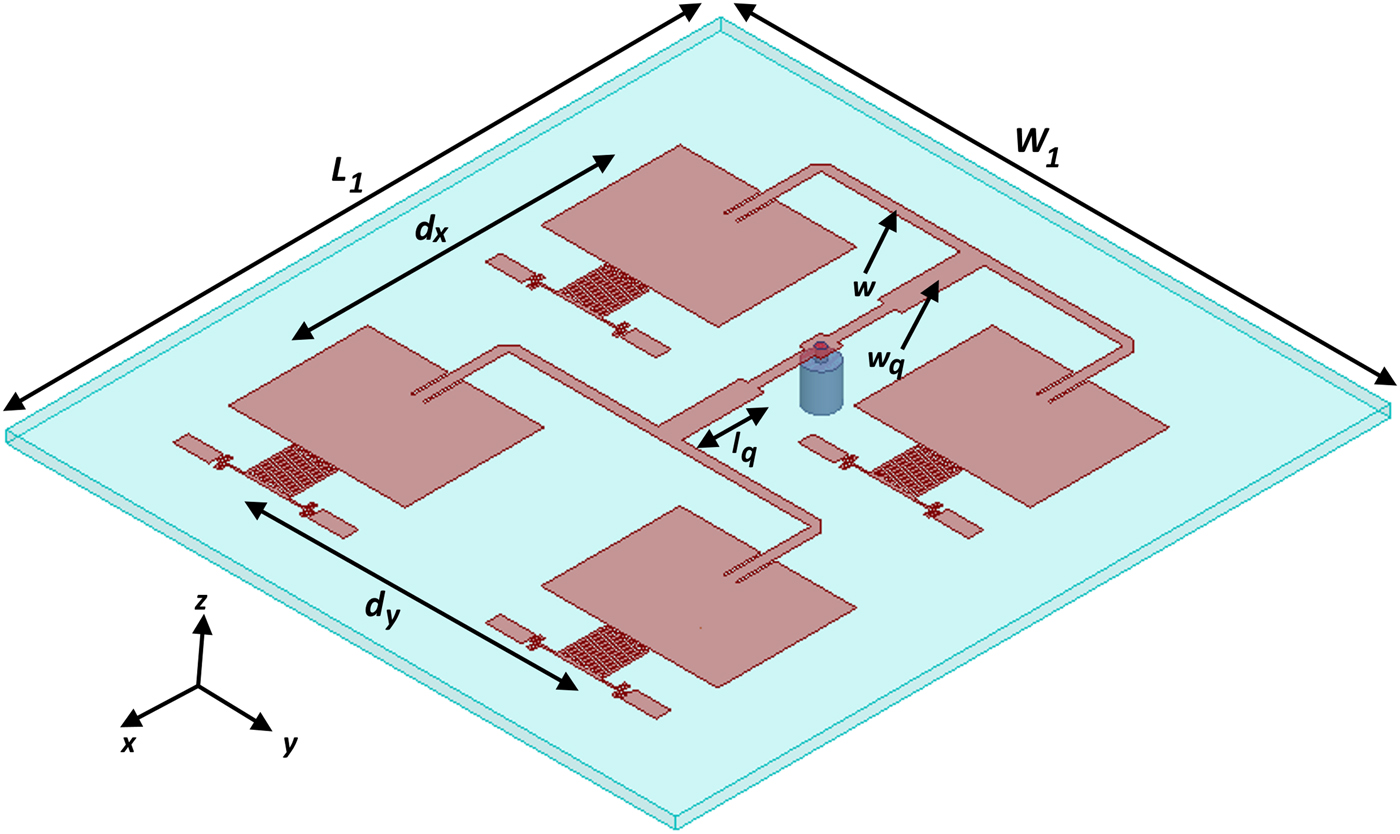
Fig. 13. Geometry of dual band CRLH TL coupled patch array (W 1 = 96, L 1 = 90, d x = 42, d y = 42, l q = 11.1, w q = 3.2, w = 1.4, all dimensions in mm).
The simulated S 11 of the dual band patch array is shown in Fig. 14. The antenna shows dual impedance bandwidth (S 11 ≤ −10 dB) of 100 MHz (from 4.77 to 4.87 GHz) and 50 MHz (from 5.13 to 5.18 GHz). Figure 15 shows the simulated E- and H-planes radiation patterns of the proposed antenna at resonance frequencies of 4.82 and 5.15 GHz. It can be observed that the simulated gain of the antenna is 13.1 and 12.7 dBi at lower and upper resonance frequencies.

Fig. 14. Simulated S 11 of dual band CRLH TL coupled patch array.

Fig. 15. Simulated radiation patterns of dual band CRLH TL coupled patch array (a) f 1 = 4.82 GHz and (b) f 2 = 5.15 GHz.
Conclusion
A new technique for designing frequency reconfigurable dual band patch antennas is presented. In this technique, a CRLH TL unit cell is gap coupled with the radiating edge of the patch antenna. The working principle is based on resonance frequency coupling of CRLH TL unit cell operating in ZOR mode and patch antenna operating in TM 10 mode. ZOR mode, which has been used in the past typically for antenna miniaturization and monopolar pattern, has been used here to achieve dual band operation with broadside pattern. It is shown that the proposed antenna has almost identical broadside radiation patterns at both resonance frequencies with reasonable radiation efficiencies. One of the benefits of the proposed scheme is that it can be used to realize frequency reconfigurable dual band patch antenna by changing the ZOR mode frequency of CRLH TL unit cell. Moreover, it can also be used to design tri-band patch antennas by gap coupling CRLH TL cell along both radiating edges of the patch. The proposed CRLH TL gap coupling technique can be employed to design single layer, multiband band frequency reconfigurable patch antennas and arrays.
 Zubair Ahmed received the B.Sc. and M.Sc. degrees in electrical engineering from the National University of Sciences and Technology (NUST), Islamabad, Pakistan, in 2003, and 2008, respectively. He is currently pursuing his Ph.D. degree at the Department of Electrical Engineering, Capital University of Science and Technology (CUST), Islamabad, Pakistan. His current research interest includes high gain and multiband patch antennas, CRLH TL-based metamaterial antennas, microwave filters, and integrated RF front ends.
 M. M. Ahmed completed the Ph.D. degree in Microelectronics from the University of Cambridge, UK, in 1995, and joined academia where he worked at different positions including Professor; Chairman; Dean and Executive Vice President. He is currently working as Vice Chancellor Capital University of Science and Technology (CUST), Islamabad. Dr. Ahmed research interests are in Microelectronics, Microwave and RF Engineering and he has supervised numerous MS and Ph.D. research projects. He authored over 100 research papers in the field of microelectronics. Dr. Ahmed is a fellow of the Institution of Engineering and Technology (IET), UK; a Chartered Engineer (CEng) from the UK Engineering Council and holds the title of European Engineer (Eur Ing) from the European Federation of National Engineering Association (FEANI), Brussels. He is a life member of PEC (Pak); EDS & MTTS (USA).
 M. B. Ihsan received the B.Sc. degree in electrical engineering from the University of Engineering and Technology, Lahore, Pakistan, in 1984 and the M.Sc. and Ph.D. degrees in electrical engineering from Drexel University, Philadelphia, PA, USA, in 1988 and 1993, respectively. In 1995, he joined the Department of Electrical Engineering, College of Electrical and Mechanical Engineering, National University of Sciences and Technology (NUST), Islamabad, Pakistan, where he has established the Microwave Engineering Research Laboratory (MERL) to conduct research and development in electronic systems, development of microwave and radar technology for biomedical applications, microwave active and passive circuits, antennas, radar signal processing, and target classification. He was the Head of the Department of Electrical Engineering, NUST, where he is currently a Professor, as well as acting as the Director of MERL. His current research interests include solid-state electronics, thin-film processing, microwave devices and circuits, and antennas.
 A. A. Chaudhary received the B.Sc. degree in electrical engineering from the National University of Sciences and Technology (NUST), Islamabad, Pakistan, in 2017. She is currently working as a research engineer at the Microwave Engineering Research Laboratory (MERL).
 J. K. Arif received the B.Sc. degree in electrical engineering from the National University of Sciences and Technology (NUST), Islamabad, Pakistan, in 2017. She is currently working as a research engineer at the Microwave Engineering Research Laboratory (MERL).