I. INTRODUCTION
Annular-ring microstrip antenna (ARMA), formed by loading a circular slot in the center of the circular patch is one of the most studied microstrip antenna because of its several useful features [Reference Balanis1–Reference Khare and Nema3]. The size of the resonant ring of the ARMA is substantially smaller than that of the corresponding circular patch. It therefore meets the requirements of miniaturized mobile applications. In ARMA, by a proper choice of the outer and inner radius of the ring, a significantly broader bandwidth than that of a circular disk microstrip antenna can be obtained [Reference Chew4]. The separation of resonant modes can also be controlled by the ratio of outer to inner radius [Reference Dahele, Lee and Wong5]. Moreover, due to their gain-bandwidth characteristics and reduced size when they are excited in the dominant mode (TM11), they have found applications in the medical field and in the satellite-based mobile communications [Reference Bahl, Stuchly and Stuchly6].
From the open literature, most of the studies on the analyses and design of the ARMAs include high assumptions and rigorous calculations of Hankel and Fourier transforms and Bessel functions. In [Reference Bahl, Stuchly and Stuchly6–Reference Pintzos and Pregla9], the ARMA was theoretically investigated as if it was a resonator and several analyses were carried out for computing the resonant frequency. A set of mathematical tools such as vector Hankel transform, Galerkin method, and Green functions were utilized in the analysis of the ARMAs [Reference Ali, Chew and Kong10–Reference Motevasselian13]. Methods based on the cavity model and the transmission line model was applied to investigate some parameters such as the resonant frequency, input impedance, and bandwidth [Reference Richards, Jai-Dong and Long14–Reference Kumar and Dhubkarya17]. Various characteristics of the antenna were analyzed with the matched asymptotic expansions technique, the perturbation approach [Reference Chew4] and the planar wave guide model [Reference Bahl and Stuchly18]. The experimental studies concerning the ARMA were also presented to confirm the theoretical calculations in [Reference Dahele, Lee and Wong5, Reference Bahl, Stuchly and Stuchly6, Reference Fan and Lee11, Reference Liu and Hu12, Reference Kumar and Dhubkarya17, Reference Dahele and Lee19–Reference Shinde, Shinde, Kumar, Uplane and Mishra22].
The methods aforementioned for the analysis and design of ARMA depend on successive mathematical derivation using complicated functions and transform techniques. Therefore, the determination of resonant frequency takes much time and also needs knowledge of mathematics. It can be clearly seen from the literature [Reference Bahl, Stuchly and Stuchly6–Reference Bahl and Stuchly18], there is no simple and accurate expression for calculating the resonant frequency of the ARMA. In order to cope with this problem, in this work, an expression based on effective radius achieving the accurate resonant frequency has been proposed. Artificial bee colony (ABC) [Reference Karaboga and Basturk23, Reference Akdagli and Toktas24] which is a recently introduced population-based optimization algorithm inspired by the intelligent foraging behavior of the honeybee was employed to form the effective radius expression of ARMA for TM11 mode. For deriving the effective radius expression, ARMAs with different electrical and physical parameters were simulated by the electromagnetic packed software IE3D™ [25], based on method of moment (MoM) [Reference Harrington26]. After the simulation process, according to these results various models for the effective radius expression including antenna dimensions and dielectric constants along with unknown optimization coefficients to be optimized were formed. In order to fit the calculated resonant frequency of effective radius expression in with the simulated ones, these parameters and respective simulated resonant frequencies were given as the input of the ABC to find the optimized unknown coefficients of the constructed effective radius expression. The accuracy and validity of the proposed expression was verified by comparing the resonant frequency results with those of reported elsewhere [Reference Wu and Rosenbaum8, Reference Pintzos and Pregla9, Reference Kumar and Dhubkarya17, Reference Bahl and Stuchly18] over the measurement data [Reference Dahele, Lee and Wong5, Reference Bahl, Stuchly and Stuchly6, Reference Fan and Lee11, Reference Liu and Hu12, Reference Kumar and Dhubkarya17, Reference Dahele and Lee19–Reference Shinde, Shinde, Kumar, Uplane and Mishra22]. It was also confirmed on an ARMA fabricated in this work.
II. THE ABC ALGORITHM
The ABC [Reference Karaboga and Basturk23, Reference Akdagli and Toktas24] is a recently emerged population-based optimization algorithm finding near optimal solutions for the difficult optimization problems by the motivation foraging behavior of the honeybee swarm. In the ABC algorithm, three kinds of bee colonies consisting of the employed, the onlooker, and the scout are considered. Bees fly around to search in a multidimensional space, in order to find an optimal solution. The employed bees are assigned to specific food sources depending on their experiences. The onlooker bees decide the food source location based on observation of the dance of employed bees within the hive and adjust their positions. The scout bees carry out a random search for determining new food sources. Initially, the half of the total colony is appointed as the employed bee and the other half as the onlooker bees. The number of food sources representing the possible solution points around the hive is assumed to be equal to that of the employed bee. Thereafter, the food sources are exploited by the employed bees and the onlooker bees. Then, the employed bee which exhausts the food sources becomes a scout bee to search further food sources once again.
The pseudocode of the ABC algorithm given below:
Initialization phase: Scouts are randomly sent to the initial food sources.
(1) Initialize the population of solutions x ij
(1)here i = 1, 2,…, FS; j = 1, 2,…, D. Where FS and D denote the size of food source and number of optimization parameters, respectively. $$x_i^j=x_{min}^j+rand\lsqb 0\comma \; 1\rsqb \lpar x_{max}^j - x_{min}^j \rpar \comma$$
(2) Evaluate the population.
(3) Cycle = 1.

Repeat
Employed bee phase: Employed bees are sent to the food sources and determine their amounts.
(4) Produce new solutions (food source positions) v ij in the neighborhood of x ij for the employed bees using the formula
(2)where k ∈ 1, 2,…, FS and j ∈ 1, 2,…, D are randomly chosen indexes. Although k is determined randomly, it has to be different from j. ϕij is a random number between [−1,1].$${v_{ij}}={x_{ij}}+{\phi _{ij}}\lpar {x_{ij}} - {x_{kj}}\rpar \comma$$(5) Apply the greedy selection process between x ij and v ij.

Onlooker bee phase: The probability value of the sources are calculated by the onlooker bees
(6) Calculate fitness values for minimization problems using the following equation:
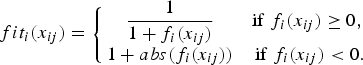
(3)$$fi{t_i}\lpar {x_{ij}}\rpar =\left\{{\matrix{ {\displaystyle{1 \over {1+{f_i}\lpar {x_{ij}}\rpar }}} & {{\rm if} \; {f_i}\lpar {x_{ij}}\rpar \geq 0 \comma \; } \cr {1+abs\lpar {f_i}\lpar {x_{ij}}\rpar \rpar } & {{\rm if} \; {f_i}\lpar {x_{ij}}\rpar \lt 0.} \cr } } \right.$$(7) The probability value p i with which x ij is chosen by an onlooker bee can be calculated using the expression given:
(4)$${p_i}=\displaystyle{{fi{t_i}\lpar {x_{ij}}\rpar } \over {\sum\nolimits_{n=1}^{FS} \, fi{t_n}\lpar {x_{ij}}\rpar }}.$$

Normalize p i values into [0,1].
(8) Produce the new solutions (new positions) v i for the onlookers from the solutions x i, selected depending on p i, and evaluate them.
(9) Apply the greedy selection process for the onlookers between x i and v i.
Scout bee phase: If a source is abandoned by an employed bee, the scout bee is randomly sent to search the area for discovering new food sources.
(10) Determine the abandoned solution (source), if it exists, and replace it with a new randomly produced solution x i for the scout bee using the equation (1).
(11) Memorize the best food source position (solution) achieved so far.
(12) Cycle = Cycle + 1.
Finalization
(13) Until cycle = Maximum Cycle Number (MCN)
At the initial phase, random values between two specified constraint values are generated for possible solution points regarding the food source location. The quality (fitness) of the generated values related to the amounts of the food is calculated to evaluate the profitability in first phase. In the onlooker bee phase, probability of the possible solution values is computed and new possible solutions are searched in the vicinity of the values with high probability. If the determined possible solution point does not improve after a specified number of trial limits, in the scout bee phase, a new value is randomly determined similar to the initial phase. Finally, the best solution point obtained is memorized. These phases sequentially continue until defined MCN.
III. THE EFFECTIVE RADIUS OF ARMA
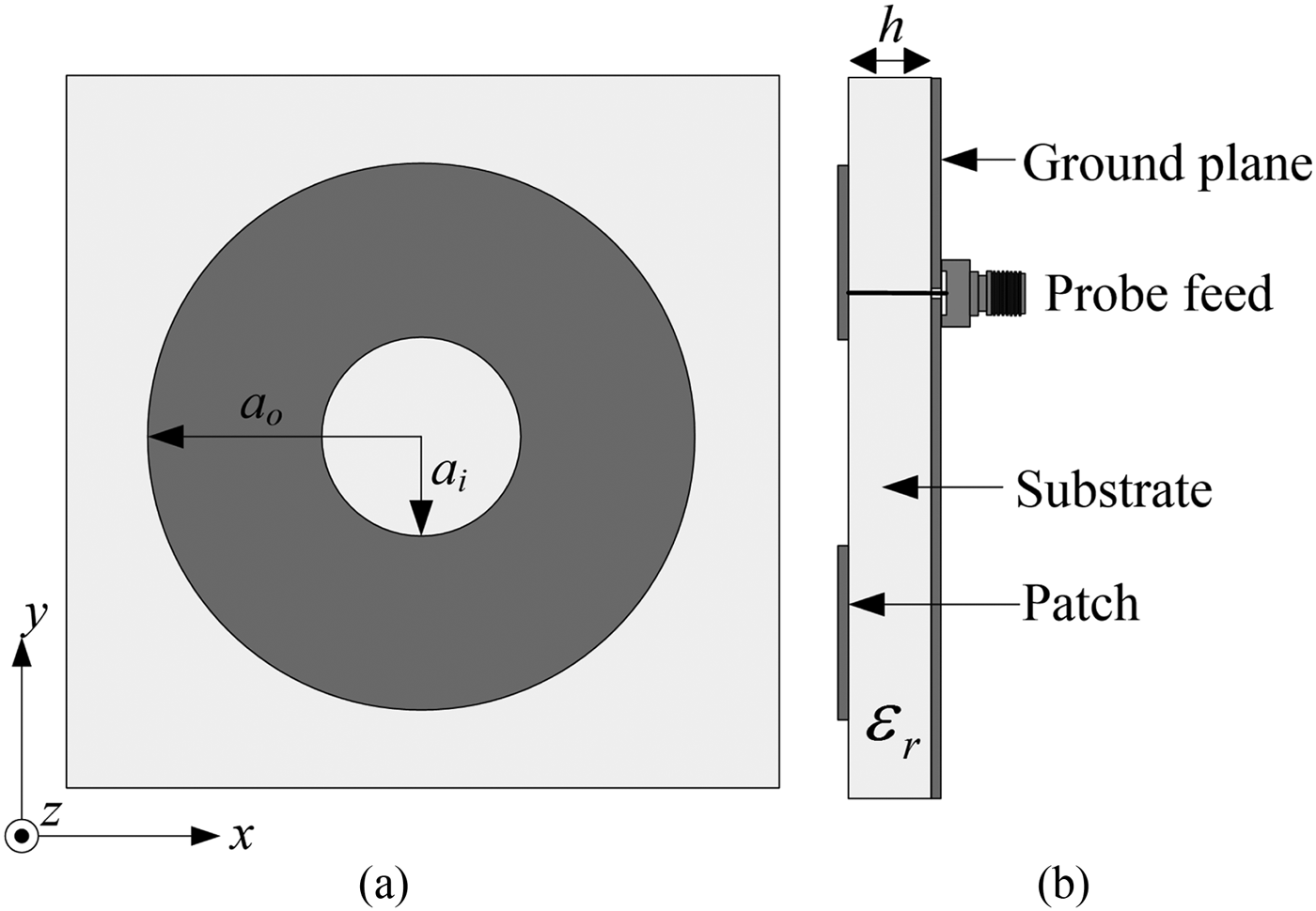
Figure 1 shows the whole geometry of an ARMA. As seen from Fig. 1(a), ARMA has an annular-ring patch with inner radius of a i and outer radius of a o. From side view of the ARMA given in Fig. 1(b), the ring patch lies on the substrate having relative dielectric constant εr and overall on the ground plane. The resonant frequency of a circular disk microstrip antenna for the TMnm mode is given by Balanis [Reference Balanis1]
 $${f_{nm}}=\displaystyle{{{X_{nm}}c} \over {2\pi a\sqrt {{{\varepsilon }_r}} }}\comma$$
where TMnm is the mth zero of the derivative of Bessel function of order n, c is the velocity of electromagnetic waves in free space, εr is the relative dielectric constant of the substrate, and a is the radius of circular patch. The dominant mode is TMnm (n = m = 1), for which X 11 = 1.8412 [Reference Balanis1].

Fig. 1. The geometry of ARMA: (a) front view (b) side view.
Since the ARMA is derived from the circular patch by slot loading, the resonant frequency expression of a circular disk microstrip can be modified for calculating the resonant frequency of the ARMA. For taking into account the effects of slot loading and fringing at the edges, the actual radius of the circular patch a is replaced by a newly introduced effective radius a eA of the ARMA. Therefore, the resonant frequency for the ARMA at TM11 mode can be written as
 $${f_{11}}=\displaystyle{{{X_{11}}c} \over {2\pi {a_{eA}}\sqrt {{{\varepsilon }_r}} }}.$$
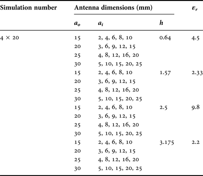
In order to construct the effective radius expression a eA, simulations by IE3D™ have been performed for 80 ARMAs, which operate over the frequency range 0.66–3.71 GHz, with different dimensions and substrate dielectric constant values tabulated in Table 1. In the simulations, the antennas were assumed to have a probe feed of 50 Ω. For the meshing process, the cell/wavelength ratio was assumed as 40 in limit of 4 GHz. The built-in optimization module of the IE3D™ was utilized to determine the feed point which gives the best return loss value with the objective function s 11(dB) < –10 for the resonant frequencies at TM11 mode.
Table 1. Physical and electrical parameters of simulated ARMAs.
Various models of the effective radius expressions including the unknown coefficients (αi) and the simulation parameters (a o, a i, h, and εr) were built to assign the best model which fits the simulation parameters in with the respective resonant frequencies. The unknown coefficients correspond to the optimization parameters (x ij; i = 1,2,…,FS; j = 1,2,…,D) in the ABC algorithm. In our problem, FS and D denote the simulation number (SN) and the number of simulation parameters, respectively. The following fitness function was utilized in the ABC algorithm.
 $$fit=\displaystyle{1 \over {1+TPE}}\comma$$
where TPE is the total percentage error to be minimized and thus the fit approaches unity. TPE is defined as
 $$TPE=\sum\limits_{k=1}^{SN} \, \left[{\left\vert {\displaystyle{{{f_{\mathop {sim}\nolimits_k }} - {f_{\mathop {cal}\nolimits_k }}} \over {{f_{\mathop {sim}\nolimits_k }}}}} \right\vert \times 100} \right]\comma$$
where f sim and f cal are the simulated and calculated resonant frequency values, respectively. In the optimization process with ABC, the colony size, MCN, limit values, initial minimum, and maximum values were chosen as 20, 1000, 20, −2, and 2, respectively. In order to assign proper effective radius expression, a series of experiments were carried out, and the expression a eA which produces satisfactory results has been constructed as
 $${a_{eA}}=\displaystyle{{{\alpha _1}\lpar {a_o}+{a_i}\rpar } \over {\left({1+{\alpha _2}{\textstyle{{{a_o}} \over {{a_i}}}}+\left({{\textstyle{h \over {\lpar {a_o}+{\alpha _3}{a_i}\rpar {{\varepsilon }_r}}}}} \right)} \right)\left({{\alpha _4}{\textstyle{{{a_o}} \over h}}+{\alpha _5}{\textstyle{{{a_o}} \over {{a_i}}}}+{\alpha _6}{{\varepsilon }_r}\lpar 1 - {\textstyle{h \over {{a_i}}}}\rpar +1} \right)}}.$$
Note that the effective radius expression models which were simpler and more complicated than that given by equation (9) were also tried. It was seen that the results of simpler models were not in good agreement with the simulation results, on the other hand the more complicated forms provide little improvement in the TPE value. The unknown coefficients of the effective radius expression were then optimally determined and these coefficients are given in Table 2. By substituting the coefficient values given in Table 2 into equation (9), the effective radius is then obtained as follows:
 $${a_{eA}}=\displaystyle{{0.85\lpar {a_o}+{a_i}\rpar } \over \left({1 - 0.007{\textstyle{{{a_o}} \over {{a_i}}}}+\left({{\textstyle{h \over {\lpar {a_o} - 1.1{a_i}\rpar {{\varepsilon }_r}}}}} \right)} \right) \left({ - 0.05{\textstyle{{{a_o}} \over h}} - 0.13{\textstyle{{{a_o}} \over {{a_i}}}}+0.18{{\varepsilon }_r}\lpar 1 - {\textstyle{h \over {{a_i}}}}\rpar +1} \right)}.$$
Eventually, the resonant frequency of an ARMA can be calculated by substituting the effective radius expression given in equation (10) into equation (6). It should be noted that dielectric constant εr is utilized in our resonant frequency expression rather than the effective dielectric constant εeff [Reference Balanis1], for the sake of simplicity, since a eA has already included the fringing effects. It should be also noted that the proposed effective annular radius expression has been formed by means of the simulated ARMAs with physical and electrical parameters given in Table 1.
Table 2. Coefficient values for effective radius expression of ARMA determined by the ABC algorithm.

IV. NUMERICAL RESULTS
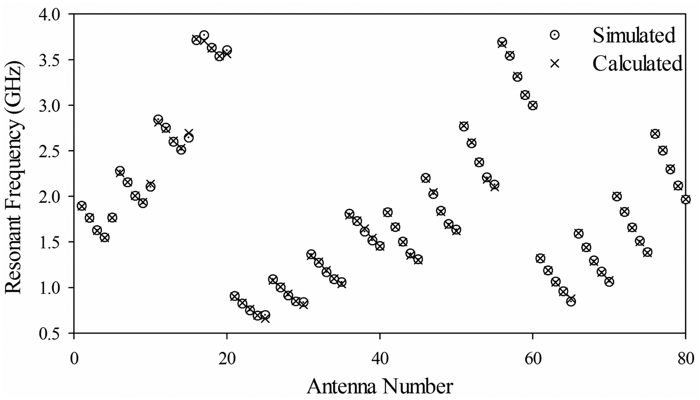
The resonant frequency results of the proposed expression obtained by the ABC algorithm and those of the numerical simulations for 80 ARMAs are plotted in Fig. 2. Average percentage error (APE) has been obtained as 0.84% for the self-consistent test. This self-consistent agreement between the simulated and calculated results supports the accuracy of the new effective radius expression. Furthermore, in order to compare the ABC algorithm with another optimization algorithm such as genetic algorithm (GA) [Reference Davis27], the unknown coefficients of the proposed expression model in equation (9) were determined by standard GA. The APE for the expression optimized by GA has been obtained as 1.04%.
Fig. 2. The simulated and calculated resonant frequency.
In order to verify the validity of the proposed expression, the resonant frequency results calculated in this study were also compared with those of several suggestions reported elsewhere [Reference Wu and Rosenbaum8, Reference Pintzos and Pregla9, Reference Kumar and Dhubkarya17, Reference Bahl and Stuchly18] over measurement results of ARMAs published earlier in the literature [Reference Dahele, Lee and Wong5, Reference Bahl, Stuchly and Stuchly6, Reference Fan and Lee11, Reference Liu and Hu12, Reference Kumar and Dhubkarya17, Reference Dahele and Lee19–Reference Shinde, Shinde, Kumar, Uplane and Mishra22]. These comparative results are given in Table 3 and the corresponding percentage errors are tabulated in Table 4. The resonant frequency results simulated using IE3D™ and HFSS™ are also given in Table 3 so as to confirm the simulations performed in this study. It is clearly seen that our simulated results agree well with measured ones. These results demonstrate that the simulation process for 80 ARMAs is very accurate, and thus the derived effective radius expression produces reliable results.
Table 3. Comparative results for resonant frequencies of ARMAs.

Table 4. Percentage errors for resonant frequencies.
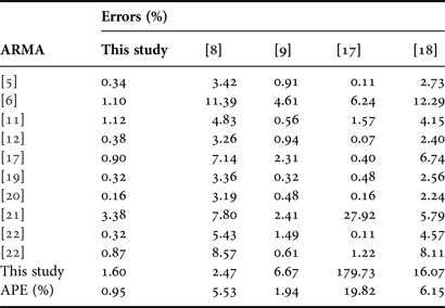
The suggestions for calculating the resonant frequency of the measured ARMAs previously published give comparable results; however, some calculations are in good agreement with measured data, and others are far off. The suggested methods produce more precise results for some particular antennas, e.g. the formulation method by Pintzos and Pregla [Reference Pintzos and Pregla9] for the antenna [Reference Fan and Lee11], and the formulation method [Reference Kumar and Dhubkarya17] for the antennas [Reference Dahele, Lee and Wong5, Reference Liu and Hu12, Reference Kumar and Dhubkarya17, Reference Dahele and Lee19, Reference Lee, Dahele and Ho20, Reference Shinde, Shinde, Kumar, Uplane and Mishra22]. However, the APE value of our proposed expression is 0.95, while it is 5.53, 1.94, 19.82, and 6.15 by suggested methods [Reference Wu and Rosenbaum8, Reference Pintzos and Pregla9, Reference Kumar and Dhubkarya17, Reference Bahl and Stuchly18], respectively. On the other hand, the APE value for our expression stays within 3.4, while it remains within 11.4, 6.7, 179.7, and 16.1 in [Reference Wu and Rosenbaum8, Reference Pintzos and Pregla9, Reference Kumar and Dhubkarya17, Reference Bahl and Stuchly18], respectively. Therefore, our resonant frequency results are generally in good agreement as compared with those calculated by other suggestions [Reference Wu and Rosenbaum8, Reference Pintzos and Pregla9, Reference Kumar and Dhubkarya17, Reference Bahl and Stuchly18]. It means that the proposed expression is more stable and reliable than those suggested in the literature. Moreover, the expression proposed here not only provides the better agreement, but also allows us to calculate the resonant frequency of ARMA in a very simple manner without dealing with any sophisticated calculations including complicated functions and transforms.
The accuracy and validity of the proposed expression were also tested on the measurement data of ARMA, which were fabricated in this work using the material of Rogers™ TMM4. The simulated and measured return loss plots obtained by using an AgilentE5071B ENA Series RF network analyzer are illustrated in Fig. 3. Note that the measurement results may include some tolerances because of material production, geometry etching, and feed connector misalignment in the fabrication process. The measured and calculated resonant frequency results of the fabricated antenna are also given in Table 3, and it can be seen that the proposed formula for resonant frequency of the ARMA provides the best fit for the measurement.
Fig. 3. The simulated and measured return loss plots.
The effective radius expression proposed in this study was validated for the parameter ranges given in Table 5 and it allows us to compute the resonant frequency with high accuracy in a simple manner as compared with the methods for ARMAs presented in the literature.
Table 5. The valid range of antenna parameters for the proposed expression.

λ d is the wavelength in the substrate.
Figure 4 shows the measured two-dimensional (2D) radiation patterns of E ϕ and E θ field for the fabricated ARMA at 3 GHz. It is seen that the radiation patterns have good performance and approaches omnidirectional radiation characteristics. The measured gain and half-power beam width (HPBW) achieved are 6.545 dBi and 110.5°, respectively.
Fig. 4. The measured radiation patterns of fabricated ARMA at 3 GHz: (a) ![]() E ϕ for θ = 90° (b)
E ϕ for θ = 90° (b) ![]() E θ for ϕ = 0° and ϕ = 90°.0
E θ for ϕ = 0° and ϕ = 90°.0
It can be clearly seen from the results given above that our calculated results using the proposed expression are better than the determined ones by other suggestions [Reference Wu and Rosenbaum8, Reference Pintzos and Pregla9, Reference Kumar and Dhubkarya17, Reference Bahl and Stuchly18]. This good agreement between the measured and our calculated resonant frequency values supports the validity of the effective radius expression obtained using the ABC algorithm. Using the expression presented here, one can easily calculate the resonant frequency of the ARMAs using a scientific calculator since it does not require complicated mathematical transformations of sophisticated functions.
V. CONCLUSION
In this study, a novel and simple effective radius expression which results in accurately calculating the resonant frequency of the ARMAs has been presented. To manage this goal, an expression was derived by utilizing the simulation data of 80 ARMA having different patch dimensions and dielectric constant values, together with ABC algorithm which is one of the most recently introduced swarm-based optimization method. The resonant frequency results obtained in this study are comparable with those of the methods proposed in the literature and the various measurement antenna data reported elsewhere. It was demonstrated that the resonant frequency values obtained from the effective radius expression are in very good agreement with the measured results as compared with those calculated by the other methods earlier. It is concluded that the advantages of expression presented in this work are the simple and the accurate.
 Abdurrahim Toktas was born in 1977. In 2002, he received his B.S. degree in Electrical and Electronics Engineering from University of Gaziantep, Turkey. He worked as telecom expert from 2003 to 2010 for Turk Telecom Company, which is the national PSTN and wideband Internet operator. In 2010, he received his M.S. degree in Electrical and Electronics Engineering from the Mersin University, Turkey. He has been working in IT Department of Mersin University and studying toward the Ph.D. degree in Electrical and Electronics Engineering from Mersin University since 2010. His current research interests include antennas, microstrip antennas, MIMO antennas, computational electromagnetic, artificial intelligent optimization algorithm, and applications of optimization algorithms to electromagnetic problem such as radiation, resonance, and bandwidth.
 Mustafa B. Bicer was born in 1988. In 2009, he received his B.S. degree in Electrical and Electronics Engineering from Firat University, Turkey. In 2012, he received his M.S. degree in Electrical and Electronics Engineering from Mersin University, Turkey. He has been working as research engineer in the Electrical and Electronics Engineering Department of Mersin University since 2009. He has been studying toward the Ph.D. degree in the same department. His current research interests include microwave imaging, antennas, microstrip antennas, computational electromagnetic, artificial intelligent, and applications of optimization algorithms to electromagnetic problem such as radiation, resonance, and bandwidth.
 Ahmet Kayabasi was born in 1980. In 2001, he received his B.S. degree in Electrical and Electronics Engineering from Selcuk University, Turkey. In 2005, he received his M.S. degree in Electrical and Electronics Engineering from Selcuk University, Turkey. He has been working as a lecturer in the Electronics and Automation Department of Silifke-Tasucu Vocational School of Selcuk University since 2001. He has been studying toward the Ph.D. degree in Electrical and Electronics Engineering from Mersin University since 2009. His current research interests include antennas, microstrip antennas, computational electromagnetic, artificial intelligent, and applications of optimization algorithms to electromagnetic problem such as radiation, resonance, and bandwidth.
 Deniz Ustun was born in 1976. In 2001, he received his B.S. degree from the Department of Computer Science Engineering, Istanbul University, Turkey. In 2009, he also received his M.S. degree in Electrical and Electronics Engineering from Mersin University, Turkey. Since 2010, he has been studying toward the Ph.D. degree at the same department. He has been working as a lecturer in the Department of Software Engineering, Mersin University since 1 year. His current research interests are artificial neural network, data mining, algorithms and theory of computation, information systems, artificial intelligent optimization algorithm, computer modeling and simulation (microstrip antennas, computational electromagnetic), and applications of optimization algorithms to electromagnetic problem such as radiation, resonance, and bandwidth.
Ali Akdagli received his B.S., M.S., and Ph.D. degrees in Electronic Engineering from Erciyes University, Kayseri, in 1995, 1997, and 2002, respectively. From 2003 to 2006, he was an Assistant Professor in the Electronic Engineering Department at Erciyes University. He joined the same department at Mersin University, where he currently works as a Professor. He has published more than 90 papers in journals and conference proceedings. His current research interests include evolutionary optimization techniques (genetic algorithm, ant colony optimization, differential evolution, particle swarm optimization, and artificial bee colony algorithms), artificial neural networks and their applications to electromagnetic, wireless communication systems, microwave circuits, microstrip antennas, and antenna pattern synthesis problems. Dr. Akdagli is an editorial board member of “Recent Patents on Electrical Engineering”, “International Journal of Computers”, and “Journal of Computational Engineering”.
 Kasim Kurt received his B.S., M.S., and Ph.D. degrees in Physics Science from Cukurova University. He started his career in a vocational school as a lecturer in Computer Programming after which he has been supported by a NATO Scholarship while studying at the Luminescence Laboratory at Sussex University, UK. He was appointed as an Assistant Professor in the Physics Department. He received his Ph.D. degree in 2004. He held a post-doctoral position from Oklahoma State University in the Radiation Measurement and Luminescence Laboratory at Physics Department for 1 year. He studied on Neutron dosimeters for Optical Stimulated Luminescence, while he was at Oklahoma State University. His current researches are characterization of luminescence materials and radiation measurement.